EP4047248A1 - Axle assembly having a sector cam - Google Patents
Axle assembly having a sector cam Download PDFInfo
- Publication number
- EP4047248A1 EP4047248A1 EP22157703.4A EP22157703A EP4047248A1 EP 4047248 A1 EP4047248 A1 EP 4047248A1 EP 22157703 A EP22157703 A EP 22157703A EP 4047248 A1 EP4047248 A1 EP 4047248A1
- Authority
- EP
- European Patent Office
- Prior art keywords
- shift
- shaft
- gear
- axis
- drive gear
- Prior art date
- Legal status (The legal status is an assumption and is not a legal conclusion. Google has not performed a legal analysis and makes no representation as to the accuracy of the status listed.)
- Granted
Links
Images





Classifications
-
- F—MECHANICAL ENGINEERING; LIGHTING; HEATING; WEAPONS; BLASTING
- F16—ENGINEERING ELEMENTS AND UNITS; GENERAL MEASURES FOR PRODUCING AND MAINTAINING EFFECTIVE FUNCTIONING OF MACHINES OR INSTALLATIONS; THERMAL INSULATION IN GENERAL
- F16H—GEARING
- F16H3/00—Toothed gearings for conveying rotary motion with variable gear ratio or for reversing rotary motion
- F16H3/02—Toothed gearings for conveying rotary motion with variable gear ratio or for reversing rotary motion without gears having orbital motion
- F16H3/08—Toothed gearings for conveying rotary motion with variable gear ratio or for reversing rotary motion without gears having orbital motion exclusively or essentially with continuously meshing gears, that can be disengaged from their shafts
- F16H3/087—Toothed gearings for conveying rotary motion with variable gear ratio or for reversing rotary motion without gears having orbital motion exclusively or essentially with continuously meshing gears, that can be disengaged from their shafts characterised by the disposition of the gears
- F16H3/089—Toothed gearings for conveying rotary motion with variable gear ratio or for reversing rotary motion without gears having orbital motion exclusively or essentially with continuously meshing gears, that can be disengaged from their shafts characterised by the disposition of the gears all of the meshing gears being supported by a pair of parallel shafts, one being the input shaft and the other the output shaft, there being no countershaft involved
-
- F—MECHANICAL ENGINEERING; LIGHTING; HEATING; WEAPONS; BLASTING
- F16—ENGINEERING ELEMENTS AND UNITS; GENERAL MEASURES FOR PRODUCING AND MAINTAINING EFFECTIVE FUNCTIONING OF MACHINES OR INSTALLATIONS; THERMAL INSULATION IN GENERAL
- F16H—GEARING
- F16H63/00—Control outputs from the control unit to change-speed- or reversing-gearings for conveying rotary motion or to other devices than the final output mechanism
- F16H63/02—Final output mechanisms therefor; Actuating means for the final output mechanisms
- F16H63/30—Constructional features of the final output mechanisms
- F16H63/32—Gear shift yokes, e.g. shift forks
-
- F—MECHANICAL ENGINEERING; LIGHTING; HEATING; WEAPONS; BLASTING
- F16—ENGINEERING ELEMENTS AND UNITS; GENERAL MEASURES FOR PRODUCING AND MAINTAINING EFFECTIVE FUNCTIONING OF MACHINES OR INSTALLATIONS; THERMAL INSULATION IN GENERAL
- F16H—GEARING
- F16H3/00—Toothed gearings for conveying rotary motion with variable gear ratio or for reversing rotary motion
- F16H3/02—Toothed gearings for conveying rotary motion with variable gear ratio or for reversing rotary motion without gears having orbital motion
- F16H3/08—Toothed gearings for conveying rotary motion with variable gear ratio or for reversing rotary motion without gears having orbital motion exclusively or essentially with continuously meshing gears, that can be disengaged from their shafts
- F16H3/087—Toothed gearings for conveying rotary motion with variable gear ratio or for reversing rotary motion without gears having orbital motion exclusively or essentially with continuously meshing gears, that can be disengaged from their shafts characterised by the disposition of the gears
-
- B—PERFORMING OPERATIONS; TRANSPORTING
- B60—VEHICLES IN GENERAL
- B60K—ARRANGEMENT OR MOUNTING OF PROPULSION UNITS OR OF TRANSMISSIONS IN VEHICLES; ARRANGEMENT OR MOUNTING OF PLURAL DIVERSE PRIME-MOVERS IN VEHICLES; AUXILIARY DRIVES FOR VEHICLES; INSTRUMENTATION OR DASHBOARDS FOR VEHICLES; ARRANGEMENTS IN CONNECTION WITH COOLING, AIR INTAKE, GAS EXHAUST OR FUEL SUPPLY OF PROPULSION UNITS IN VEHICLES
- B60K17/00—Arrangement or mounting of transmissions in vehicles
- B60K17/02—Arrangement or mounting of transmissions in vehicles characterised by arrangement, location, or kind of clutch
-
- B—PERFORMING OPERATIONS; TRANSPORTING
- B60—VEHICLES IN GENERAL
- B60K—ARRANGEMENT OR MOUNTING OF PROPULSION UNITS OR OF TRANSMISSIONS IN VEHICLES; ARRANGEMENT OR MOUNTING OF PLURAL DIVERSE PRIME-MOVERS IN VEHICLES; AUXILIARY DRIVES FOR VEHICLES; INSTRUMENTATION OR DASHBOARDS FOR VEHICLES; ARRANGEMENTS IN CONNECTION WITH COOLING, AIR INTAKE, GAS EXHAUST OR FUEL SUPPLY OF PROPULSION UNITS IN VEHICLES
- B60K17/00—Arrangement or mounting of transmissions in vehicles
- B60K17/04—Arrangement or mounting of transmissions in vehicles characterised by arrangement, location or kind of gearing
- B60K17/06—Arrangement or mounting of transmissions in vehicles characterised by arrangement, location or kind of gearing of change-speed gearing
- B60K17/08—Arrangement or mounting of transmissions in vehicles characterised by arrangement, location or kind of gearing of change-speed gearing of mechanical type
-
- F—MECHANICAL ENGINEERING; LIGHTING; HEATING; WEAPONS; BLASTING
- F16—ENGINEERING ELEMENTS AND UNITS; GENERAL MEASURES FOR PRODUCING AND MAINTAINING EFFECTIVE FUNCTIONING OF MACHINES OR INSTALLATIONS; THERMAL INSULATION IN GENERAL
- F16H—GEARING
- F16H63/00—Control outputs from the control unit to change-speed- or reversing-gearings for conveying rotary motion or to other devices than the final output mechanism
- F16H63/02—Final output mechanisms therefor; Actuating means for the final output mechanisms
- F16H63/08—Multiple final output mechanisms being moved by a single common final actuating mechanism
- F16H63/16—Multiple final output mechanisms being moved by a single common final actuating mechanism the final output mechanisms being successively actuated by progressive movement of the final actuating mechanism
- F16H63/18—Multiple final output mechanisms being moved by a single common final actuating mechanism the final output mechanisms being successively actuated by progressive movement of the final actuating mechanism the final actuating mechanism comprising cams
-
- B—PERFORMING OPERATIONS; TRANSPORTING
- B60—VEHICLES IN GENERAL
- B60K—ARRANGEMENT OR MOUNTING OF PROPULSION UNITS OR OF TRANSMISSIONS IN VEHICLES; ARRANGEMENT OR MOUNTING OF PLURAL DIVERSE PRIME-MOVERS IN VEHICLES; AUXILIARY DRIVES FOR VEHICLES; INSTRUMENTATION OR DASHBOARDS FOR VEHICLES; ARRANGEMENTS IN CONNECTION WITH COOLING, AIR INTAKE, GAS EXHAUST OR FUEL SUPPLY OF PROPULSION UNITS IN VEHICLES
- B60K1/00—Arrangement or mounting of electrical propulsion units
-
- B—PERFORMING OPERATIONS; TRANSPORTING
- B60—VEHICLES IN GENERAL
- B60K—ARRANGEMENT OR MOUNTING OF PROPULSION UNITS OR OF TRANSMISSIONS IN VEHICLES; ARRANGEMENT OR MOUNTING OF PLURAL DIVERSE PRIME-MOVERS IN VEHICLES; AUXILIARY DRIVES FOR VEHICLES; INSTRUMENTATION OR DASHBOARDS FOR VEHICLES; ARRANGEMENTS IN CONNECTION WITH COOLING, AIR INTAKE, GAS EXHAUST OR FUEL SUPPLY OF PROPULSION UNITS IN VEHICLES
- B60K1/00—Arrangement or mounting of electrical propulsion units
- B60K2001/001—Arrangement or mounting of electrical propulsion units one motor mounted on a propulsion axle for rotating right and left wheels of this axle
-
- F—MECHANICAL ENGINEERING; LIGHTING; HEATING; WEAPONS; BLASTING
- F16—ENGINEERING ELEMENTS AND UNITS; GENERAL MEASURES FOR PRODUCING AND MAINTAINING EFFECTIVE FUNCTIONING OF MACHINES OR INSTALLATIONS; THERMAL INSULATION IN GENERAL
- F16H—GEARING
- F16H63/00—Control outputs from the control unit to change-speed- or reversing-gearings for conveying rotary motion or to other devices than the final output mechanism
- F16H63/02—Final output mechanisms therefor; Actuating means for the final output mechanisms
- F16H63/30—Constructional features of the final output mechanisms
- F16H2063/3079—Shift rod assembly, e.g. supporting, assembly or manufacturing of shift rails or rods; Special details thereof
-
- F—MECHANICAL ENGINEERING; LIGHTING; HEATING; WEAPONS; BLASTING
- F16—ENGINEERING ELEMENTS AND UNITS; GENERAL MEASURES FOR PRODUCING AND MAINTAINING EFFECTIVE FUNCTIONING OF MACHINES OR INSTALLATIONS; THERMAL INSULATION IN GENERAL
- F16H—GEARING
- F16H63/00—Control outputs from the control unit to change-speed- or reversing-gearings for conveying rotary motion or to other devices than the final output mechanism
- F16H63/02—Final output mechanisms therefor; Actuating means for the final output mechanisms
- F16H63/30—Constructional features of the final output mechanisms
- F16H63/32—Gear shift yokes, e.g. shift forks
- F16H2063/321—Gear shift yokes, e.g. shift forks characterised by the interface between fork body and shift rod, e.g. fixing means, bushes, cams or pins
-
- F—MECHANICAL ENGINEERING; LIGHTING; HEATING; WEAPONS; BLASTING
- F16—ENGINEERING ELEMENTS AND UNITS; GENERAL MEASURES FOR PRODUCING AND MAINTAINING EFFECTIVE FUNCTIONING OF MACHINES OR INSTALLATIONS; THERMAL INSULATION IN GENERAL
- F16H—GEARING
- F16H2200/00—Transmissions for multiple ratios
- F16H2200/0021—Transmissions for multiple ratios specially adapted for electric vehicles
-
- F—MECHANICAL ENGINEERING; LIGHTING; HEATING; WEAPONS; BLASTING
- F16—ENGINEERING ELEMENTS AND UNITS; GENERAL MEASURES FOR PRODUCING AND MAINTAINING EFFECTIVE FUNCTIONING OF MACHINES OR INSTALLATIONS; THERMAL INSULATION IN GENERAL
- F16H—GEARING
- F16H2200/00—Transmissions for multiple ratios
- F16H2200/003—Transmissions for multiple ratios characterised by the number of forward speeds
- F16H2200/0039—Transmissions for multiple ratios characterised by the number of forward speeds the gear ratios comprising three forward speeds
-
- F—MECHANICAL ENGINEERING; LIGHTING; HEATING; WEAPONS; BLASTING
- F16—ENGINEERING ELEMENTS AND UNITS; GENERAL MEASURES FOR PRODUCING AND MAINTAINING EFFECTIVE FUNCTIONING OF MACHINES OR INSTALLATIONS; THERMAL INSULATION IN GENERAL
- F16H—GEARING
- F16H2702/00—Combinations of two or more transmissions
- F16H2702/02—Mechanical transmissions with planetary gearing combined with one or more other mechanical transmissions
- F16H2702/04—Combinations of a speed-change mechanism without planetary gearing with a differential for driving a vehicle drive axle
-
- F—MECHANICAL ENGINEERING; LIGHTING; HEATING; WEAPONS; BLASTING
- F16—ENGINEERING ELEMENTS AND UNITS; GENERAL MEASURES FOR PRODUCING AND MAINTAINING EFFECTIVE FUNCTIONING OF MACHINES OR INSTALLATIONS; THERMAL INSULATION IN GENERAL
- F16H—GEARING
- F16H37/00—Combinations of mechanical gearings, not provided for in groups F16H1/00 - F16H35/00
- F16H37/02—Combinations of mechanical gearings, not provided for in groups F16H1/00 - F16H35/00 comprising essentially only toothed or friction gearings
- F16H37/04—Combinations of toothed gearings only
- F16H37/042—Combinations of toothed gearings only change gear transmissions in group arrangement
Definitions
- This relates to an axle assembly that has a sector cam that controls movement of at least one shift collar.
- a drivetrain assembly having a shift mechanism that includes a sector cam is disclosed in U.S. Patent No. 10,900,564 .
- an axle assembly may include a first shaft, a second shaft, a first set of gears, a second set of gears, a first shift collar, a second shift collar, and a sector cam.
- the first shaft may be rotatable about a first axis.
- the second shaft may be rotatable about a second axis.
- the first set of gears may be rotatable about the first axis.
- the second set of gears may be rotatable about the second axis.
- Each member of the second set of gears may mesh with a different member of the first set of gears.
- the first shift collar may be rotatable about the first axis with the first shaft and may be moveable along the first axis with respect to the first shaft to selectively connect a member of the first set of gears to the first shaft.
- the second shift collar may be rotatable about the second axis with the second shaft and may be moveable along the second axis with respect to the second shaft to selectively connect a member of the second set of gears to the second shaft.
- the sector cam may be rotatable about a sector cam axis and may be operatively connected to the first shift collar and to the second shift collar. Rotation of the sector cam about the sector cam axis may control movement of the first shift collar along the first axis and may control movement of the second shift collar along the second axis.
- the axle assembly 10 may be provided with a vehicle like a truck, bus, farm equipment, mining equipment, military transport or weaponry vehicle, or cargo loading equipment for land, air, or marine vessels.
- the vehicle may include a trailer for transporting cargo in one or more embodiments.
- the axle assembly 10 may provide torque to one or more traction wheel assemblies that may include a tire 12 mounted on a wheel 14.
- the wheel 14 may be mounted to a wheel hub that may be rotatable about a wheel axis 16.
- the axle assembly 10 may include or may be operatively connected to a torque source 20.
- the torque source 20 may be of any suitable type.
- the torque source 20 may be a non-electrical torque source, an electrical torque source, or combinations thereof.
- An example of a non-electrical torque source is an internal combustion engine.
- An example of an electrical torque source is an electric motor 22.
- An electric motor 22 may include a stator 24 and a rotor 26 that may be rotatable about an axis.
- An electrical power source 28 such as a battery, capacitor, generator, or the like, may be electrically connected to an electric motor 22 in a manner known by those skilled in the art.
- the axle assembly 10 may include a differential assembly 30, at least one axle shaft 32, and a transmission 34.
- the axle assembly 10 may also include a shift mechanism 36 as shown in Figure 2 .
- the differential assembly 30 may transmit torque to the vehicle traction wheel assemblies and permit the traction wheel assemblies to rotate at different velocities.
- the differential assembly 30 may be operatively connected to the axle shafts 32 and may permit the axle shafts 32 to rotate at different rotational speeds in a manner known by those skilled in the art.
- the differential assembly 30 may be rotatable about a differential axis 40 and may transmit torque to the axle shafts 32 and wheels.
- the differential axis 40 may be coaxially disposed with the wheel axis 16 in one or more configurations.
- the differential assembly 30 may have a ring gear 42 that may have teeth that mate or mesh with the teeth of a gear portion 44 of a drive pinion 46 that may be associated with the transmission 34. Accordingly, the differential assembly 30 may receive torque from the drive pinion 46 via the ring gear 42 and transmit torque to the axle shafts 32.
- the axle shafts 32 may transmit torque between the differential assembly 30 and the traction wheel assemblies.
- Two axle shafts 32 may be provided that may extend in opposite directions from the differential assembly 30.
- Each axle shaft 32 may have a first end and a second end. The first end may be operatively connected to the differential assembly 30. The second end may be disposed opposite the first end and may be operatively connected to a wheel.
- the axle shafts 32 or a portion thereof may extend along and may be rotatable about an axis, such as the differential axis 40.
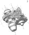
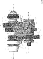
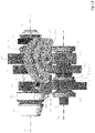
- the transmission 34 may transmit torque between the torque source 20 and the differential assembly 30. Torque transmission may be bidirectional. In at least one configuration such as is shown in Figures 3 and 4 , the transmission 34 may include a first shaft 50, a first set of gears 52, and a first shift collar 54. The transmission 34 may also include a second shaft 60, a second set of gears 62, and a second shift collar 64 as is best shown in Figures 5 and 6 .
- the first shaft 50 may be rotatable about a first axis 70.
- the first axis 70 may be substantially perpendicular to the differential axis 40.
- the term "substantially perpendicular” is used herein to designate features such as axes that are the perpendicular or very close to perpendicular with respect to each other and includes features that are within ⁇ 2° of being perpendicular each other.
- the first shaft 50 may be rotatably supported by one or more bearings, such as a first bearing 72 and a second bearing 74.
- the first bearing 72 and the second bearing 74 may have any suitable configuration.
- first bearing 72 and the second bearing 74 may be configured as roller bearing assemblies that may encircle the first shaft 50.
- the first shaft 50 may be part of the drive pinion 46 or may be rotatable with the drive pinion 46.
- the first set of gears 52 may include a plurality of gears that may be rotatable about the first axis 70.
- the first set of gears 52 includes a first drive gear 80, a second drive gear 82, and a third drive gear 84; however, it is to be understood that a greater or lesser number of gears may be provided.
- a member of the first set of gears 52 may be rotatable about the first axis 70 with the first shaft 50 when that gear is coupled to the first shaft 50.
- the first shaft 50 may be rotatable about the first axis 70 with respect to a member of the first set of gears 52 that is decoupled from or not coupled to the first shaft 50.
- a member of the first set of gears 52 may be selectively coupled to the first shaft 50 with the first shift collar 54 as will be discussed in more detail below.
- the first drive gear 80 may receive the first shaft 50.
- the first drive gear 80 may have a through hole through which the first shaft 50 may extend.
- the first drive gear 80 may extend around the first axis 70 and the first shaft 50 and may have a plurality of teeth that may be arranged around and may face away from the first axis 70.
- the teeth of the first drive gear 80 may contact and may mate or mesh with teeth of a first gear of the second set of gears 62 as will be discussed in more detail below.
- the first drive gear 80 may be fixedly coupled to the first shaft 50 such that the first drive gear 80 is rotatable about the first axis 70 with the first shaft 50 and such that the first drive gear 80 does not rotate about the first axis 70 with respect to the first shaft 50.
- the first drive gear 80 may be axially positioned along the first axis 70 between the gear portion 44 and the second drive gear 82.
- the first drive gear 80 may be axially positioned between the first bearing 72 and a spacer 86.
- the second drive gear 82 may receive the first shaft 50.
- the second drive gear 82 may have a through hole through which the first shaft 50 may extend.
- the second drive gear 82 may extend around the first axis 70 and the first shaft 50 and may have a plurality of teeth that may be arranged around and may face away from the first axis 70.
- the teeth of the second drive gear 82 may contact and may mate or mesh with teeth of a second gear of the second set of gears 62 as will be discussed in more detail below.
- the second drive gear 82 may be fixedly coupled to the first shaft 50 such that the second drive gear 82 is rotatable about the first axis 70 with the first shaft 50 and such that the second drive gear 82 does not rotate about the first axis 70 with respect to the first shaft 50.
- the second drive gear 82 may be axially positioned along the first axis 70 between the first drive gear 80 and the third drive gear 84.
- the second drive gear 82 may be axially positioned closer to the third drive gear 84 than to the first drive gear 80.
- the spacer 86 may be positioned between the first drive gear 80 and the second drive gear 82 to separate or increase the axial distance between the first drive gear 80 and the second drive gear 82 to provide alignment with a corresponding member of the second set of gears 62, which may be arranged to accommodate the second shift collar 64 as will be discussed in more detail below.
- the second drive gear 82 may have a different diameter than the first drive gear 80.
- the second drive gear 82 may have a larger diameter than the first drive gear 80.
- the third drive gear 84 may receive the first shaft 50.
- the third drive gear 84 may have a through hole through which the first shaft 50 may extend.
- the third drive gear 84 may extend around the first axis 70 and the first shaft 50 and may have a plurality of teeth that may be arranged around and may face away from the first axis 70.
- the teeth of the third drive gear 84 may contact and may mate or mesh with teeth of a third gear of the second set of gears 62 as will be discussed in more detail below.
- the third drive gear 84 may be rotatably disposed on the first shaft 50.
- a bearing or bushing 88 may be received in the hole of the third drive gear 84 to rotatably support the third drive gear 84 on the first shaft 50.
- the bushing 88 may also have a flange that may extend away from the first axis 70 and that may help separate the third drive gear 84 from the second drive gear 82.
- the third drive gear 84 may include clutch engagement teeth 90 that may be engaged by the first shift collar 54 to selectively couple the third drive gear 84 to the first shaft 50 as will be discussed in more detail below.
- the clutch engagement teeth 90 may have any suitable configuration.
- the clutch engagement teeth 90 are configured as a spline gear or spline teeth in which teeth may be arranged around the first axis 70 and may face away from and extend radially away from the first axis 70.
- the clutch engagement teeth 90 may be configured as a face gear in which teeth may the arranged around the first axis 70 and may extend axially from a side of the third drive gear 84 toward the first shift collar 54.
- the third drive gear 84 may be axially positioned along the first axis 70 between the second drive gear 82 and the first shift collar 54.
- the third drive gear 84 may have a different diameter than the first drive gear 80 and the second drive gear 82.
- the third drive gear 84 may have a larger diameter than the second drive gear 82.
- the first shift collar 54 may be axially positioned between the third drive gear 84 and the second bearing 74.
- the first shift collar 54 may receive the first shaft 50 and may be rotatable about the first axis 70 with the first shaft 50.
- the first shift collar 54 may be moveable along the first axis 70 with respect to the first shaft 50 to selectively couple or selectively connect a member of the first set of gears 52 to the first shaft 50.
- the first shift collar 54 may selectively couple the third drive gear 84 to the first shaft 50 as is shown in phantom in Figure 4 and as will be discussed in more detail below.
- the first shift collar 54 may include a first shift collar hole 100 and a first shift collar spline 102.
- the first shift collar hole 100 may extend along the first axis 70.
- the first shift collar hole 100 may be a through hole through which the first shaft 50 may extend.
- the first shift collar spline 102 may operatively connect the first shift collar 54 to the first shaft 50.
- the first shift collar spline 102 may be disposed in the first shift collar hole 100 and may include spline teeth that may extend toward the first axis 70.
- the spline teeth may mesh or mate with corresponding spline teeth on the first shaft 50 or that are disposed on an intervening component that may be fixedly mounted to the first shaft 50, such as a first annular ring 110, which is best shown in Figure 4 .
- the first annular ring 110 may have spline teeth 112 that may extend away from the first axis 70 and that may mesh with the teeth of the first shift collar spline 102.
- the first annular ring 110 may at least partially encircle the first shaft 50 and may extend axially between the second bearing 74 and the third drive gear 84 and/or its bushing 88.
- the first shift collar spline 102 may selectively engage the third drive gear 84 to permit or inhibit rotation of the third drive gear 84 with respect to the first shaft 50.
- the third drive gear 84 may be rotatable about the first axis 70 with respect to the first shaft 50 when the first shift collar 54 is disengaged from the third drive gear 84.
- the third drive gear 84 may be rotatable with respect to the first shaft 50 when the first shift collar spline 102 does not mate or mesh with the clutch engagement teeth 90 of the third drive gear 84 and thus the first shift collar 54 does not connect the third drive gear 84 to the first shaft 50.
- the third drive gear 84 may be rotatable about the first axis 70 with the first shaft 50 when the first shift collar 54 connects the third drive gear 84 to the first shaft 50, such as when the first shift collar spline 102 mates or meshes with the clutch engagement teeth 90 of the third drive gear 84. It is also contemplated that the first shift collar 54 may be provided with a face gear that may mate or mesh with clutch engagement teeth 90 of the third drive gear 84 that may also be configured as a face gear. In such a configuration, the first shift collar spline 102 may not mate or mesh with the clutch engagement teeth 90.
- the second shaft 60 may be spaced apart from the first shaft 50 and may be rotatable about a second axis 120.
- the second axis 120 may be disposed substantially parallel to the first axis 70.
- the term "substantially parallel” is used herein to designate features such as axes that are the parallel or very close to parallel with respect to each other and includes features that are within ⁇ 2° of being parallel each other.
- the second shaft 60 may be rotatably supported by one or more bearings, such as a first bearing 122 and a second bearing 124.
- the first bearing 122 and the second bearing 124 may have any suitable configuration.
- first bearing 122 and the second bearing 124 may be configured as roller bearing assemblies that may encircle the second shaft 60.
- the second shaft 60 may be operatively connected to the torque source 20.
- torque may be transmitted from the torque source 20 to the second shaft 60, and then torque may be transmitted from the second shaft 60 to the first shaft 50 via gears.
- the second shaft 60 may be operatively connected to the rotor 26, such as by directly connecting a rotor shaft to the second shaft 60 or by using a connecting gear set 126, an example of which is best shown in Figure 1 .
- the connecting gear set 126 may have a first connecting gear that is rotatable with the rotor 26 and that meshes with a second connecting gear that is rotatable with the second shaft 60.
- the transmission 34 may be positioned on an opposite side of the differential assembly 30 from the torque source 20.
- the second set of gears 62 may include a plurality of gears that may be rotatable about the second axis 120. Each member of the second set of gears 62 may mesh with a different member of the first set of gears 52. In the configuration shown, the second set of gears 62 includes first gear 130, a second gear 132, and a third gear 134; however, it is to be understood that a greater or lesser number of gears may be provided. A member of the second set of gears 62 may be rotatable about the second axis 120 with the second shaft 60 when that gear is coupled to the second shaft 60.
- the second shaft 60 may be rotatable about the second axis 120 with respect to a member of the second set of gears 62 that is decoupled from or not coupled to the second shaft 60.
- a member of the second set of gears 62 may be selectively coupled to the second shaft 60 with the second shift collar 64 as will be discussed in more detail below.
- the first gear 130 may receive the second shaft 60.
- the first gear 130 may have a through hole through which the second shaft 60 may extend.
- the first gear 130 may extend around the second axis 120 and the second shaft 60 and may have a plurality of teeth that may be arranged around and may face away from the second axis 120.
- the teeth of the first gear 130 may contact and may mate or mesh with teeth of the first drive gear 80 of the first set of gears 52.
- the first gear 130 may be rotatably disposed on the second shaft 60.
- a bearing or bushing 140 may be received in the hole of the first gear 130 and may rotatably support the first gear 130 on the second shaft 60.
- the first gear 130 may include clutch engagement teeth 150 that may be engaged by the second shift collar 64 to selectively couple the first gear 130 to the second shaft 60 as will be discussed in more detail below.
- the clutch engagement teeth 150 may have any suitable configuration.
- the clutch engagement teeth 150 are configured as a spline gear or spline teeth in which teeth may be arranged around the second axis 120 and may face away from and extend radially away from the second axis 120.
- the clutch engagement teeth 150 may be configured as a face gear in which teeth may the arranged around the second axis 120 and may extend axially from a side of the first gear 130 toward the second shift collar 64.
- the first gear 130 may be axially positioned along the second axis 120 between the first bearing 122 and the second gear 132.
- the second gear 132 may receive the second shaft 60.
- the second gear 132 may have a through hole through which the second shaft 60 may extend.
- the second gear 132 may extend around the second axis 120 and the second shaft 60 and may have a plurality of teeth that may be arranged around and may face away from the second axis 120.
- the teeth of the second gear 132 may contact and may mate or mesh with teeth of a second drive gear 82 of the first set of gears 52.
- the second gear 132 may be rotatably disposed on the second shaft 60.
- a bearing or bushing 140 may be received in the hole of the second gear 132 and may rotatably support the second gear 132 on the second shaft 60.
- the second gear 132 may include second clutch engagement teeth 160 that may be engaged by the second shift collar 64 to selectively couple the second gear 132 to the second shaft 60 as will be discussed in more detail below.
- the second clutch engagement teeth 160 may have any suitable configuration.
- the second clutch engagement teeth 160 are configured as a spline gear or spline teeth in which teeth may be arranged around the second axis 120 and may face away from and extend radially away from the second axis 120.
- the second clutch engagement teeth 160 may be configured as a face gear in which teeth may the arranged around the second axis 120 and may extend axially from a side of the second gear 132 toward the second shift collar 64.
- the second gear 132 may be axially positioned along the second axis 120 between the first gear 130 and the third gear 134.
- the second gear 132 may be axially positioned between the second shift collar 64 and the third gear 134.
- the second gear 132 may be axially positioned closer to the third gear 134 than to the first gear 130.
- a spacer 170 may be positioned between the first gear 130 and the second gear 132 to separate or increase the axial distance between the first gear 130 and the second gear 132 to provide sufficient room for moving the second shift collar 64 as will be discussed in more detail below.
- the spacer 170 may be integrally formed with the second shaft 60 or may be provided as a separate component that may extend from the second shaft 60.
- the second gear 132 may have a different diameter than the first gear 130.
- the second gear 132 may have a smaller diameter than the first gear 130.
- the third gear 134 may receive the second shaft 60.
- the third gear 134 may have a through hole through which the second shaft 60 may extend.
- the third gear 134 may extend around the second axis 120 and the second shaft 60 and may have a plurality of teeth that may be arranged around and may face away from the second axis 120.
- the teeth of the third gear 134 may contact and may mate or mesh with teeth of the third drive gear 84 of the first set of gears 52 as will be discussed in more detail below.
- the third gear 134 may be fixedly coupled to the second shaft 60 such that the third gear 134 is rotatable about the second axis 120 with the second shaft 60 and such that the third gear 134 does not rotate about the second axis 120 with respect to the second shaft 60.
- the third gear 134 may be axially positioned along the second axis 120 between the second bearing 124 and the second drive gear 82.
- the third gear 134 may have a different diameter than the first gear 130 and the second gear 132. For instance, the third gear 134 may have a smaller diameter than the second gear 132.
- the second shift collar 64 may be axially positioned between the first gear 130 and the second gear 132.
- the second shift collar 64 may receive the second shaft 60 and may be rotatable about the first axis 70 with the second shaft 60.
- the second shift collar 64 may be moveable along the second axis 120 with respect to the second shaft 60 to may selectively couple or selectively connect a member of the second set of gears 62 to the second shaft 60.
- the second shift collar 64 may selectively couple the first gear 130 or the second gear 132 to the second shaft 60 as will be discussed in more detail below.
- the second shift collar 64 may also decouple the first gear 130 and the second gear 132 from the second shaft 60 in an intermediate portion that is shown in phantom on Figure 6 .
- the second shift collar 64 may include a second shift collar hole 180 and a second shift collar spline 182.
- the second shift collar hole 180 may extend along the second axis 120.
- the second shift collar hole 180 may be a through hole through which the second shaft 60 may extend.
- the second shift collar spline 182 may operatively connect the second shift collar 64 to the second shaft 60.
- the second shift collar spline 182 may be disposed in the second shift collar hole 180 and may include spline teeth that may extend toward the second axis 120.
- the spline teeth may mesh or mate with corresponding spline teeth on the second shaft 60 or and intervening component that may be fixedly mounted to the second shaft 60.
- the second shift collar spline 182 may selectively engage the first gear 130 or the second gear 132 to permit or inhibit rotation of the first gear 130 or the second gear 132 with respect to the second shaft 60.
- the second shift collar spline 182 may mate or mesh with the clutch engagement teeth 150 of the first gear 130 to rotatably couple the first gear 130 to the second shaft 60 as shown in solid lines at position A in Figure 6 .
- the first gear 130 may be rotatable about the second axis 120 with respect to the second shaft 60 when the second shift collar 64 is disengaged from the first gear 130 or does not connect the first gear 130 to the second shaft 60.
- the first gear 130 may be rotatable about the second axis 120 with respect to the second shaft 60 when the second shift collar spline 182 does not mate or mesh with the clutch engagement teeth 150 of the first gear 130.
- the second shift collar spline 182 may not mate or mesh with the clutch engagement teeth 150 of the first gear 130 and the second clutch engagement teeth 160 of the second gear 132 when in the intermediate position shown with phantom lines at position B, thereby permitting the second shaft 60 to rotate with respect to the first gear 130 and the second gear 132.
- the second shift collar spline 182 may mate or mesh with the second clutch engagement teeth 160 of the second gear 132 to rotatably couple the second gear 132 to the second shaft 60 when the second shift collar 64 is moved to the right from the perspective shown in Figure 6 to position C.
- the second gear 132 may be rotatable about the second axis 120 with respect to the second shaft 60 when the second shift collar 64 is disengaged from the second gear 132 or does not connect the second gear 132 to the second shaft 60.
- the second gear 132 may be rotatable about the second axis 120 with respect to the second shaft 60 when the second shift collar spline 182 does not mate or mesh with the second clutch engagement teeth 160 of the second gear 132.
- the second shift collar 64 may be provided with a face gear that may mate or mesh with clutch engagement teeth 150 of the first gear 130 that may also be configured as a face gear, may be provided with a face gear that may mate or mesh with the second clutch engagement teeth 160 of the second gear 132 that may be configured as a face gear, or combinations thereof.
- the shift mechanism 36 may control positioning of a shift collar, such as the first shift collar 54 and the second shift collar 64.
- the shift mechanism 36 may include a shift rail 200, a first shift fork 202, a second shift fork 204, a sector cam 206, or combinations thereof.
- the shift rail 200 may extend along a shift rail axis 210.
- the shift rail axis 210 may be disposed substantially parallel to the first axis 70, the second axis 120, or both. In at least one configuration, the shift rail axis 210 may be disposed closer to the first axis 70 than to the second axis 120.
- the shift rail 200 may be fixedly positioned such that the shift rail 200 may not move along or rotate about the shift rail axis 210.
- the shift rail 200 may be spaced apart from the sector cam 206 and may support the first shift fork 202 and the second shift fork 204.
- the first shift fork 202 may operatively connect the first shift collar 54 to the sector cam 206.
- the first shift fork 202 may be slidable along the shift rail axis 210 with respect to the shift rail 200.
- the first shift fork 202 may include a tubular portion 220 and a fork arm 222.
- a shift bracket 224 may be associated with the first shift fork 202.
- the tubular portion 220 may receive the shift rail 200.
- the tubular portion 220 may have a first end 230, a second end 232, and a shift fork hole 234.
- the first end 230 may face toward the second shift fork 204.
- the second end 232 may be disposed opposite the first end 230. As such, the second end 232 may face away from the second shift fork 204.
- the shift fork hole 234 may extend from the first end 230 to the second end 232.
- the shift rail 200 may extend through the shift fork hole 234.
- the fork arm 222 may extend from the tubular portion 220 to the first shift collar 54.
- the fork arm 222 may have any suitable configuration.
- the fork arm 222 may have a pair of prongs that may be received in a groove of the first shift collar 54 and that may allow the first shift collar 54 to rotate about the first axis 70 with respect to the prongs.
- the fork arm 222 may be disposed proximate the second end 232 of the tubular portion 220.
- the shift bracket 224 may operatively connect the first shift fork 202 to the sector cam 206.
- the shift bracket 224 may be slidable along the shift rail 200 with the first shift fork 202 and may support a guide feature 226 that may engage the sector cam 206.
- the shift bracket 224 may have a first flange 240, a second flange 242, and a body portion 244.
- the first flange 240 may be disposed at a first end of the body portion 244.
- the first flange 240 may define a hole through which the shift rail 200 may extend.
- the first flange 240 may engage the first end 230 of the tubular portion 220.
- the second flange 242 may be disposed at a second end of the body portion 244 that may be disposed opposite the first end.
- the second flange 242 may define a hole through which the shift rail 200 may extend.
- the second flange 242 may engage the second end 232 of the tubular portion 220.
- the first flange 240 and the second flange 242 may engage opposite ends of the first shift fork 202 and the first shift fork 202 may be positioned between the first flange 240 and the second flange 242 to inhibit relative axial movement of the shift bracket 224 with respect to first shift fork 202.
- the body portion 244 may extend from the first flange 240 to the second flange 242.
- the body portion 244 may extend generally parallel to the shift rail 200 and may be spaced apart from the shift rail 200 and the sector cam 206.
- the guide feature 226 may operatively connect the first shift fork 202 to the sector cam 206.
- the guide feature 226, which may be referred to as a first guide feature, may extend from the body portion 244 in a direction that extends toward the sector cam 206.
- the guide feature 226 may have any suitable configuration.
- the guide feature 226 may be a roller that may be received in a first groove of the sector cam 206 as will be discussed in more detail below.
- the guide feature 226 may be disposed closer to the first flange 240 than to the second flange 242. It is also contemplated that the shift bracket 224 may be omitted and that the guide feature 226 may be provided with the first shift fork 202.
- the second shift fork 204 may be spaced apart from the first shift fork 202.
- the second shift fork 204 may operatively connect the second shift collar 64 to the sector cam 206.
- the second shift fork 204 may have a similar configuration as the first shift fork 202.
- the second shift fork 204 may be slidable along the shift rail axis 210 with respect to the shift rail 200.
- the second shift fork 204 may include a tubular portion 220' and a fork arm 222'.
- a shift bracket 224' may be associated with the second shift fork 204.
- the tubular portion 220' may receive the shift rail 200.
- the tubular portion 220' may have a first end 230', a second end 232', and a shift fork hole 234'.
- the first end 230' may face away from the first shift fork 202.
- the second end 232' may be disposed opposite the first end 230'. As such, the second end 232' may face toward the first shift fork 202.
- the shift fork hole 234' may extend from the first end 230' to the second end 232'.
- the shift rail 200 may extend through the shift fork hole 234'.
- the fork arm 222' may extend from the tubular portion 220' of the second shift fork 204 to the second shift collar 64.
- the fork arm 222' may have any suitable configuration.
- the fork arm 222' may have a pair of prongs that may be received in a groove of the second shift collar 64 and that may allow the second shift collar 64 to rotate about the second axis 120 with respect to the prongs.
- the fork arm 222' may be disposed closer to the first end 230' of the tubular portion 220' than to the second end 232'.
- the shift bracket 224' may operatively connect the second shift fork 204 to the sector cam 206.
- the shift bracket 224' may be slidable along the shift rail 200 with the second shift fork 204 and may support a guide feature 226' that may engage the sector cam 206.
- the shift bracket 224' may have the same configuration as the shift bracket 224.
- the shift bracket 224' may have a first flange 240', a second flange 242', and a body portion 244'.
- the first flange 240' may be disposed at a first end of the body portion 244'.
- the first flange 240' may define a hole through which the shift rail 200 may extend.
- the first flange 240' may engage the first end 230' of the tubular portion 220'.
- the second flange 242' may be disposed at a second end of the body portion 244' that may be disposed opposite the first end.
- the second flange 242' may define a hole through which the shift rail 200 may extend.
- the second flange 242' may engage the second end 232' of the tubular portion 220'.
- the first flange 240' and the second flange 242' may engage opposite ends of the second shift fork 204 and the second shift fork 204 may be positioned between the first flange 240' and the second flange 242' to inhibit relative axial movement of the shift bracket 224' with respect to second shift fork 204.
- the body portion 244' may extend from the first flange 240' to the second flange 242'.
- the body portion 244' may extend generally parallel to the shift rail 200 and may be spaced apart from the shift rail 200 and the sector cam 206.
- the guide feature 226' may operatively connect the second shift fork 204 to the sector cam 206.
- the guide feature 226' which may be referred to as a second guide feature, may extend from the body portion 244' in a direction that extends toward the sector cam 206.
- the guide feature 226' may have the same configuration as the guide feature 226 that is associated with the first shift fork 202.
- the guide feature 226' may be a roller that may be received in a second groove of the sector cam 206 as will be discussed in more detail below.
- the guide feature 226' may be axially positioned closer to the second flange 242' than to the first flange 240'. It is also contemplated that the shift bracket 224' may be omitted and that the guide feature 226' may be provided with the second shift fork 204.
- the sector cam 206 may be operatively connected to the first shift collar 54, the second shift collar 64, or both.
- the sector cam 206 may be spaced apart from the transmission 34 and the shift rail 200.
- the sector cam 206 may have a generally flat or planar configuration.
- the sector cam 206 may be rotatable about a sector cam axis 250.
- the sector cam axis 250 may be disposed substantially perpendicular to the first axis 70, the second axis 120, the shift rail axis 210, or combinations thereof. Rotation of the sector cam 206 about the sector cam axis 250 may control movement of the first shift collar 54 along the first axis 70, may control movement of the second shift collar 64 along the second axis 120, or both.
- the sector cam 206 may have a coupling feature 260 and an arcuate exterior side 262.
- the sector cam 206 may define one or more grooves, such as a first groove 264 and a second groove 266.
- the coupling feature 260 may facilitate coupling of the sector cam 206 to an actuator that may rotate the sector cam 206 about the sector cam axis 250.
- the coupling feature 260 may have any suitable configuration.
- the coupling feature 260 may have a male configuration, a female configuration, or combinations thereof.
- the actuator may have any suitable configuration.
- the actuator may be an electrical actuator, mechanical actuator, electromechanical actuator, or the like.
- the arcuate exterior side 262 may face away from the sector cam axis 250.
- the arcuate exterior side 262 or a portion thereof may extend along an arc, such as an arc that may be radially disposed with respect to the sector cam axis 250.
- a plurality of detent features 270 may be provided with the arcuate exterior side 262.
- the detent features 270 may be spaced apart from each other and may be positioned to correspond with rotational positions of the sector cam 206, such as the positions shown in Figures 8-11 .
- the detent features 270 may have any suitable configuration. For instance, a detent feature 270 may be configured as an indentation that may extend toward the sector cam axis 250.
- a detent feature 270 may be engaged by a detent mechanism 272, which is best shown in Figures 8-11 .
- the detent feature 270 may be mounted to a stationary component, such as a housing of the axle assembly 10.
- the detent feature 270 may help hold the sector cam 206 in a desired rotational position.
- the detent mechanism 272 may slide along the arcuate exterior side 262 when the sector cam 206 is rotated about the sector cam axis 250 between different rotational positions and their associated detent features 270.
- the first groove 264 may guide movement of the first shift fork 202 and thus guide movement of the first shift collar 54.
- the first groove 264 may be defined by the sector cam 206 such that the first groove 264 may be completely disposed inside the sector cam 206 or encircled by the sector cam 206.
- the first groove 264 may be spaced apart from the sector cam axis 250 and the second groove 266 and may receive the guide feature 226 of the first shift fork 202.
- the guide feature 226 may extend into the first groove 264.
- the first groove 264 may be radially positioned between the sector cam axis 250 and the arcuate exterior side 262.
- first groove 264 may be radially positioned between the coupling feature 260 and the second groove 266. As such, the first groove 264 may be positioned closer to the sector cam axis 250 than the second groove 266 is positioned to the sector cam axis 250.
- the first groove 264 may extend in a nonlinear manner between a first end and a second end. In at least one configuration, the first groove 264 may have a first groove side 280 and a second groove side 282.
- the first groove side 280 and the second groove side 282 may be spaced apart from each other and may extend between the first end and the second end of the first groove 264.
- the first groove side 280 and the second groove side 282 may be mirror images of each other and may be equidistantly spaced from each other.
- the first groove side 280 and the second groove side 282 may be disposed substantially parallel to each other in one or more embodiments.
- the first groove side 280 and the second groove side 282 may cooperate to constrain and control axial movement of the first shift fork 202.
- the guide feature 226 of the first shift fork 202 may engage the first groove side 280 to inhibit movement of the first shift fork 202 to the right from the perspective shown while the guide feature 226 may engage the second groove side 282 to inhibit movement of the first shift fork 202 to the left from the perspective shown.
- the second groove 266 may guide movement of the second shift fork 204 and thus guide movement of the second shift collar 64.
- the second groove 266 may be defined by the sector cam 206 such that the second groove 266 may be completely disposed inside the sector cam 206 or encircled by the sector cam 206.
- the second groove 266 may be spaced apart from the first groove 264 and the arcuate exterior side 262 and may receive the guide feature 226' of the second shift fork 204.
- the guide feature 226' may extend into the second groove 266.
- the second groove 266 may be radially positioned between the sector cam axis 250 and the arcuate exterior side 262.
- the second groove 266 may be radially positioned between the first groove 264 and the arcuate exterior side 262.
- the second groove 266 may extend in a nonlinear manner between a first end and a second end.
- the second groove 266 may have a greater length between the first end and the second end than the first groove 264.
- the second groove 266 may have a first groove side 280' and a second groove side 282'.
- the first groove side 280' and the second groove side 282' may be spaced apart from each other and may extend between the first end and the second end of the second groove 266.
- the first groove side 280' and the second groove side 282' may be mirror images of each other and may be equidistantly spaced from each other.
- the first groove side 280' and the second groove side 282' may be disposed substantially parallel to each other in one or more embodiments.
- the first groove side 280' and the second groove side 282' may cooperate to constrain and control axial movement of the second shift fork 204.
- the guide feature 226' of the second shift fork 204 may engage the first groove side 280' to inhibit movement of the second shift fork 204 to the right from the perspective shown while the guide feature 226' may engage the second groove side 282' to inhibit movement of the second shift fork 204 to the left from the perspective shown.
- Rotation of the sector cam 206 and shifting of a shift collar may occur in response to an operator command, may be automated, or combinations thereof.
- a shift may be executed when the rotational speed of a shift collar and the gear that is being engaged or disengaged are sufficiently synchronized.
- Sufficient synchronization to permit shifting or movement of a collar may be attained using a synchronizer, by controlling the rotational speed of the first shaft 50, by controlling the rotational speed of the second shaft 60, or combinations thereof.
- shift collar positions are shown; however, it is to be understood that the shift collar positions may be rearranged or additional shift collar positions may be added, in which case the length of the first groove 264, the length of the second groove 266, the manner in which the first groove 264 and the second groove 266 bend or jog with respect to each other, or combinations thereof, may differ from the example shown.
- the sector cam 206 is shown in a low-speed position.
- the first shift collar 54 may couple the third drive gear 84 to the first shaft 50 such that the third drive gear 84 is rotatable with the first shaft 50.
- the second shift collar 64 may not couple the first gear 130 or the second gear 132 to the second shaft 60. As such, torque may be transmitted between the first shaft 50 and the second shaft 60 via the third drive gear 84 and the third gear 134.
- the guide feature 226 of the first shift fork 202 may be disposed adjacent to the first end of the first groove 264 and the guide feature 226' of the second shift fork 204 may be disposed adjacent to the first end of the second groove 266 when the sector cam 206 is in the low-speed position.
- the sector cam 206 is shown in a mid-speed position.
- the first shift collar 54 may not couple the third drive gear 84 to the first shaft 50 and is moved to the right from the position shown in Figure 8 .
- the second shift collar 64 is moved to the right from the position shown in Figure 8 and may couple the second gear 132 to the second shaft 60 but may not couple the first gear 130 to the second shaft 60. As such, torque may be transmitted between the first shaft 50 and the second shaft 60 via the second drive gear 82 and the second gear 132.
- the guide feature 226 of the first shift fork 202 and the guide feature 226' of the second shift fork 204 may be disposed closer to the sector cam axis 250 when the sector cam 206 is in the mid-speed position as compared to the low-speed position.
- the sector cam 206 is shown in a neutral position.
- the first shift collar 54 is in the same position as in Figure 9 may not couple the third drive gear 84 to the first shaft 50.
- the second shift collar 64 is in the same position as Figure 8 and may not couple the first gear 130 or the second gear 132 to the second shaft 60. As such, torque may not be transmitted between the first shaft 50 and the second shaft 60.
- the guide feature 226 of the first shift fork 202 may be disposed at the same distance from the sector cam axis 250 in the neutral and mid-speed positions.
- the guide feature 226' of the second shift fork 204 may be disposed further from the sector cam axis 250 in the neutral position as compared to the mid-speed position.
- the sector cam 206 is shown in a high-speed position.
- the first shift collar 54 is in the same position as in Figure 9 and may not couple the third drive gear 84 to the first shaft 50.
- the second shift collar 64 is moved to the left from the position shown in Figure 8 to couple the first gear 130 to the second shaft 60 but does not couple the second gear 132 to the second shaft 60. As such, torque may be transmitted between the first shaft 50 and the second shaft 60 via the first drive gear 80 and the first gear 130.
- the guide feature 226 of the first shift fork 202 may be disposed adjacent to the second end of the first groove 264 and the guide feature 226' of the second shift fork 204 may be disposed adjacent to the second end of the second groove 266 when the sector cam 206 is in the high-speed position.
- An axle assembly as discussed above may allow a torque source and a transmission to be arranged on opposite sides of a differential assembly.
- the torque source is an electric motor
- such a configuration may help thermally separate the electric motor and heat generated by its fast-spinning rotor bearings (which may rotate at speeds greater than 50,000 rpm) from other components of the axle assembly, such as the transmission and lubricant of the axle assembly.
- This thermal separation may improve thermal management of the axle assembly and may reduce lubricant heating, which may help improve lubricant life.
- such an arrangement may provide better weight distribution by locating the center of mass of the axle assembly closer to the axle shafts as compared to a configuration in which the electric motor and transmission extend from the same side of the housing assembly.
- axle assembly having a sector cam as described above may allow a compact shift mechanism to be provided, which may help reduce package space, weight, associated cost, or combinations thereof.
- a sector cam may allow shift collars to be actuated simultaneously or independently and with a high degree of accuracy.
Landscapes
- Engineering & Computer Science (AREA)
- General Engineering & Computer Science (AREA)
- Mechanical Engineering (AREA)
- Chemical & Material Sciences (AREA)
- Combustion & Propulsion (AREA)
- Transportation (AREA)
- Gear-Shifting Mechanisms (AREA)
- Arrangement And Mounting Of Devices That Control Transmission Of Motive Force (AREA)
Abstract
Description
- This relates to an axle assembly that has a sector cam that controls movement of at least one shift collar.
- A drivetrain assembly having a shift mechanism that includes a sector cam is disclosed in
U.S. Patent No. 10,900,564 - In at least one embodiment an axle assembly is provided. The axle assembly may include a first shaft, a second shaft, a first set of gears, a second set of gears, a first shift collar, a second shift collar, and a sector cam. The first shaft may be rotatable about a first axis. The second shaft may be rotatable about a second axis. The first set of gears may be rotatable about the first axis. The second set of gears may be rotatable about the second axis. Each member of the second set of gears may mesh with a different member of the first set of gears. The first shift collar may be rotatable about the first axis with the first shaft and may be moveable along the first axis with respect to the first shaft to selectively connect a member of the first set of gears to the first shaft. The second shift collar may be rotatable about the second axis with the second shaft and may be moveable along the second axis with respect to the second shaft to selectively connect a member of the second set of gears to the second shaft. The sector cam may be rotatable about a sector cam axis and may be operatively connected to the first shift collar and to the second shift collar. Rotation of the sector cam about the sector cam axis may control movement of the first shift collar along the first axis and may control movement of the second shift collar along the second axis.
-
-
Figure 1 is a schematic representation of an example of an axle assembly. -
Figure 2 is a perspective view of an example of a transmission and a shift mechanism that may be provided with the axle assembly. -
Figure 3 is a perspective view of a portion of the transmission that is associated with a first shaft. -
Figure 4 is a section view along section line 4-4. -
Figure 5 is a perspective view of a portion of the transmission that is associated with a second shaft. -
Figure 6 is a section view along section line 6-6. -
Figure 7 is a perspective view of the shift mechanism. -
Figure 8 is a side view showing the shift mechanism in a low-speed position. -
Figure 9 is side view showing the shift mechanism in a mid-speed position. -
Figure 10 is a side view showing the shift mechanism in a neutral position. -
Figure 11 is a side view showing the shift mechanism in a high-speed position. - As required, detailed embodiments of the present invention are disclosed herein; however, it is to be understood that the disclosed embodiments are merely exemplary of the invention that may be embodied in various and alternative forms. The figures are not necessarily to scale; some features may be exaggerated or minimized to show details of particular components. Therefore, specific structural and functional details disclosed herein are not to be interpreted as limiting, but merely as a representative basis for teaching one skilled in the art to variously employ the present invention.
- Referring to
Figure 1 , an example of anaxle assembly 10 is shown. Theaxle assembly 10 may be provided with a vehicle like a truck, bus, farm equipment, mining equipment, military transport or weaponry vehicle, or cargo loading equipment for land, air, or marine vessels. The vehicle may include a trailer for transporting cargo in one or more embodiments. - The
axle assembly 10 may provide torque to one or more traction wheel assemblies that may include atire 12 mounted on awheel 14. Thewheel 14 may be mounted to a wheel hub that may be rotatable about awheel axis 16. - The
axle assembly 10 may include or may be operatively connected to atorque source 20. Thetorque source 20 may be of any suitable type. For instance, thetorque source 20 may be a non-electrical torque source, an electrical torque source, or combinations thereof. An example of a non-electrical torque source is an internal combustion engine. An example of an electrical torque source is anelectric motor 22. Anelectric motor 22 may include astator 24 and arotor 26 that may be rotatable about an axis. Anelectrical power source 28 such as a battery, capacitor, generator, or the like, may be electrically connected to anelectric motor 22 in a manner known by those skilled in the art. - In at least one configuration, the
axle assembly 10 may include adifferential assembly 30, at least oneaxle shaft 32, and atransmission 34. Theaxle assembly 10 may also include ashift mechanism 36 as shown inFigure 2 . - Referring to
Figure 1 , thedifferential assembly 30 may transmit torque to the vehicle traction wheel assemblies and permit the traction wheel assemblies to rotate at different velocities. In addition, thedifferential assembly 30 may be operatively connected to theaxle shafts 32 and may permit theaxle shafts 32 to rotate at different rotational speeds in a manner known by those skilled in the art. For instance, thedifferential assembly 30 may be rotatable about adifferential axis 40 and may transmit torque to theaxle shafts 32 and wheels. Thedifferential axis 40 may be coaxially disposed with thewheel axis 16 in one or more configurations. In at least one configuration, thedifferential assembly 30 may have aring gear 42 that may have teeth that mate or mesh with the teeth of agear portion 44 of adrive pinion 46 that may be associated with thetransmission 34. Accordingly, thedifferential assembly 30 may receive torque from thedrive pinion 46 via thering gear 42 and transmit torque to theaxle shafts 32. - The
axle shafts 32 may transmit torque between thedifferential assembly 30 and the traction wheel assemblies. Twoaxle shafts 32 may be provided that may extend in opposite directions from thedifferential assembly 30. Eachaxle shaft 32 may have a first end and a second end. The first end may be operatively connected to thedifferential assembly 30. The second end may be disposed opposite the first end and may be operatively connected to a wheel. Theaxle shafts 32 or a portion thereof may extend along and may be rotatable about an axis, such as thedifferential axis 40. - The
transmission 34 may transmit torque between thetorque source 20 and thedifferential assembly 30. Torque transmission may be bidirectional. In at least one configuration such as is shown inFigures 3 and4 , thetransmission 34 may include afirst shaft 50, a first set ofgears 52, and afirst shift collar 54. Thetransmission 34 may also include asecond shaft 60, a second set ofgears 62, and asecond shift collar 64 as is best shown inFigures 5 and6 . - Referring primarily to
Figures 3 and4 , thefirst shaft 50 may be rotatable about afirst axis 70. As is shown inFigure 1 , thefirst axis 70 may be substantially perpendicular to thedifferential axis 40. The term "substantially perpendicular" is used herein to designate features such as axes that are the perpendicular or very close to perpendicular with respect to each other and includes features that are within ±2° of being perpendicular each other. For instance, thefirst shaft 50 may be rotatably supported by one or more bearings, such as afirst bearing 72 and asecond bearing 74. Thefirst bearing 72 and thesecond bearing 74 may have any suitable configuration. For example, thefirst bearing 72 and thesecond bearing 74 may be configured as roller bearing assemblies that may encircle thefirst shaft 50. In at least one configuration, thefirst shaft 50 may be part of thedrive pinion 46 or may be rotatable with thedrive pinion 46. - The first set of
gears 52 may include a plurality of gears that may be rotatable about thefirst axis 70. In the configuration shown, the first set ofgears 52 includes afirst drive gear 80, asecond drive gear 82, and athird drive gear 84; however, it is to be understood that a greater or lesser number of gears may be provided. A member of the first set ofgears 52 may be rotatable about thefirst axis 70 with thefirst shaft 50 when that gear is coupled to thefirst shaft 50. Conversely, thefirst shaft 50 may be rotatable about thefirst axis 70 with respect to a member of the first set ofgears 52 that is decoupled from or not coupled to thefirst shaft 50. A member of the first set ofgears 52 may be selectively coupled to thefirst shaft 50 with thefirst shift collar 54 as will be discussed in more detail below. - The
first drive gear 80 may receive thefirst shaft 50. For example, thefirst drive gear 80 may have a through hole through which thefirst shaft 50 may extend. Thefirst drive gear 80 may extend around thefirst axis 70 and thefirst shaft 50 and may have a plurality of teeth that may be arranged around and may face away from thefirst axis 70. The teeth of thefirst drive gear 80 may contact and may mate or mesh with teeth of a first gear of the second set ofgears 62 as will be discussed in more detail below. In at least one configuration, thefirst drive gear 80 may be fixedly coupled to thefirst shaft 50 such that thefirst drive gear 80 is rotatable about thefirst axis 70 with thefirst shaft 50 and such that thefirst drive gear 80 does not rotate about thefirst axis 70 with respect to thefirst shaft 50. In at least one configuration, thefirst drive gear 80 may be axially positioned along thefirst axis 70 between thegear portion 44 and thesecond drive gear 82. For instance, thefirst drive gear 80 may be axially positioned between thefirst bearing 72 and aspacer 86. - The
second drive gear 82 may receive thefirst shaft 50. For example, thesecond drive gear 82 may have a through hole through which thefirst shaft 50 may extend. Thesecond drive gear 82 may extend around thefirst axis 70 and thefirst shaft 50 and may have a plurality of teeth that may be arranged around and may face away from thefirst axis 70. The teeth of thesecond drive gear 82 may contact and may mate or mesh with teeth of a second gear of the second set ofgears 62 as will be discussed in more detail below. In at least one configuration, thesecond drive gear 82 may be fixedly coupled to thefirst shaft 50 such that thesecond drive gear 82 is rotatable about thefirst axis 70 with thefirst shaft 50 and such that thesecond drive gear 82 does not rotate about thefirst axis 70 with respect to thefirst shaft 50. In at least one configuration, thesecond drive gear 82 may be axially positioned along thefirst axis 70 between thefirst drive gear 80 and thethird drive gear 84. In addition, thesecond drive gear 82 may be axially positioned closer to thethird drive gear 84 than to thefirst drive gear 80. For instance, thespacer 86 may be positioned between thefirst drive gear 80 and thesecond drive gear 82 to separate or increase the axial distance between thefirst drive gear 80 and thesecond drive gear 82 to provide alignment with a corresponding member of the second set ofgears 62, which may be arranged to accommodate thesecond shift collar 64 as will be discussed in more detail below. In addition, thesecond drive gear 82 may have a different diameter than thefirst drive gear 80. For example, thesecond drive gear 82 may have a larger diameter than thefirst drive gear 80. - The
third drive gear 84 may receive thefirst shaft 50. For example, thethird drive gear 84 may have a through hole through which thefirst shaft 50 may extend. Thethird drive gear 84 may extend around thefirst axis 70 and thefirst shaft 50 and may have a plurality of teeth that may be arranged around and may face away from thefirst axis 70. The teeth of thethird drive gear 84 may contact and may mate or mesh with teeth of a third gear of the second set ofgears 62 as will be discussed in more detail below. Thethird drive gear 84 may be rotatably disposed on thefirst shaft 50. A bearing or bushing 88 may be received in the hole of thethird drive gear 84 to rotatably support thethird drive gear 84 on thefirst shaft 50. The bushing 88 may also have a flange that may extend away from thefirst axis 70 and that may help separate thethird drive gear 84 from thesecond drive gear 82. - As is best shown in
Figure 4 , thethird drive gear 84 may include clutch engagement teeth 90 that may be engaged by thefirst shift collar 54 to selectively couple thethird drive gear 84 to thefirst shaft 50 as will be discussed in more detail below. The clutch engagement teeth 90 may have any suitable configuration. In the configuration shown, the clutch engagement teeth 90 are configured as a spline gear or spline teeth in which teeth may be arranged around thefirst axis 70 and may face away from and extend radially away from thefirst axis 70. Alternatively or in addition, the clutch engagement teeth 90 may be configured as a face gear in which teeth may the arranged around thefirst axis 70 and may extend axially from a side of thethird drive gear 84 toward thefirst shift collar 54. Thethird drive gear 84 may be axially positioned along thefirst axis 70 between thesecond drive gear 82 and thefirst shift collar 54. In addition, thethird drive gear 84 may have a different diameter than thefirst drive gear 80 and thesecond drive gear 82. For example, thethird drive gear 84 may have a larger diameter than thesecond drive gear 82. - The
first shift collar 54 may be axially positioned between thethird drive gear 84 and thesecond bearing 74. Thefirst shift collar 54 may receive thefirst shaft 50 and may be rotatable about thefirst axis 70 with thefirst shaft 50. In addition, thefirst shift collar 54 may be moveable along thefirst axis 70 with respect to thefirst shaft 50 to selectively couple or selectively connect a member of the first set ofgears 52 to thefirst shaft 50. For instance, thefirst shift collar 54 may selectively couple thethird drive gear 84 to thefirst shaft 50 as is shown in phantom inFigure 4 and as will be discussed in more detail below. In at least one configuration and as is best shown inFigure 7 , thefirst shift collar 54 may include a firstshift collar hole 100 and a firstshift collar spline 102. - The first
shift collar hole 100 may extend along thefirst axis 70. The firstshift collar hole 100 may be a through hole through which thefirst shaft 50 may extend. - The first
shift collar spline 102 may operatively connect thefirst shift collar 54 to thefirst shaft 50. The firstshift collar spline 102 may be disposed in the firstshift collar hole 100 and may include spline teeth that may extend toward thefirst axis 70. The spline teeth may mesh or mate with corresponding spline teeth on thefirst shaft 50 or that are disposed on an intervening component that may be fixedly mounted to thefirst shaft 50, such as a first annular ring 110, which is best shown inFigure 4 . For instance, the first annular ring 110 may havespline teeth 112 that may extend away from thefirst axis 70 and that may mesh with the teeth of the firstshift collar spline 102. The first annular ring 110 may at least partially encircle thefirst shaft 50 and may extend axially between thesecond bearing 74 and thethird drive gear 84 and/or its bushing 88. - The first
shift collar spline 102 may selectively engage thethird drive gear 84 to permit or inhibit rotation of thethird drive gear 84 with respect to thefirst shaft 50. Thethird drive gear 84 may be rotatable about thefirst axis 70 with respect to thefirst shaft 50 when thefirst shift collar 54 is disengaged from thethird drive gear 84. For instance, thethird drive gear 84 may be rotatable with respect to thefirst shaft 50 when the firstshift collar spline 102 does not mate or mesh with the clutch engagement teeth 90 of thethird drive gear 84 and thus thefirst shift collar 54 does not connect thethird drive gear 84 to thefirst shaft 50. Thethird drive gear 84 may be rotatable about thefirst axis 70 with thefirst shaft 50 when thefirst shift collar 54 connects thethird drive gear 84 to thefirst shaft 50, such as when the firstshift collar spline 102 mates or meshes with the clutch engagement teeth 90 of thethird drive gear 84. It is also contemplated that thefirst shift collar 54 may be provided with a face gear that may mate or mesh with clutch engagement teeth 90 of thethird drive gear 84 that may also be configured as a face gear. In such a configuration, the firstshift collar spline 102 may not mate or mesh with the clutch engagement teeth 90. - Referring primarily to
Figures 5 and6 , thesecond shaft 60 may be spaced apart from thefirst shaft 50 and may be rotatable about asecond axis 120. Thesecond axis 120 may be disposed substantially parallel to thefirst axis 70. The term "substantially parallel" is used herein to designate features such as axes that are the parallel or very close to parallel with respect to each other and includes features that are within ±2° of being parallel each other. Thesecond shaft 60 may be rotatably supported by one or more bearings, such as afirst bearing 122 and asecond bearing 124. Thefirst bearing 122 and thesecond bearing 124 may have any suitable configuration. For instance, thefirst bearing 122 and thesecond bearing 124 may be configured as roller bearing assemblies that may encircle thesecond shaft 60. Thesecond shaft 60 may be operatively connected to thetorque source 20. For example, torque may be transmitted from thetorque source 20 to thesecond shaft 60, and then torque may be transmitted from thesecond shaft 60 to thefirst shaft 50 via gears. In a configuration having an electrical power source, thesecond shaft 60 may be operatively connected to therotor 26, such as by directly connecting a rotor shaft to thesecond shaft 60 or by using a connecting gear set 126, an example of which is best shown inFigure 1 . For instance, the connecting gear set 126 may have a first connecting gear that is rotatable with therotor 26 and that meshes with a second connecting gear that is rotatable with thesecond shaft 60. In at least one configuration, thetransmission 34 may be positioned on an opposite side of thedifferential assembly 30 from thetorque source 20. - Referring again to
Figures 5 and6 , the second set ofgears 62 may include a plurality of gears that may be rotatable about thesecond axis 120. Each member of the second set ofgears 62 may mesh with a different member of the first set ofgears 52. In the configuration shown, the second set ofgears 62 includesfirst gear 130, asecond gear 132, and athird gear 134; however, it is to be understood that a greater or lesser number of gears may be provided. A member of the second set ofgears 62 may be rotatable about thesecond axis 120 with thesecond shaft 60 when that gear is coupled to thesecond shaft 60. Conversely, thesecond shaft 60 may be rotatable about thesecond axis 120 with respect to a member of the second set ofgears 62 that is decoupled from or not coupled to thesecond shaft 60. A member of the second set ofgears 62 may be selectively coupled to thesecond shaft 60 with thesecond shift collar 64 as will be discussed in more detail below. - The
first gear 130 may receive thesecond shaft 60. For example, thefirst gear 130 may have a through hole through which thesecond shaft 60 may extend. Thefirst gear 130 may extend around thesecond axis 120 and thesecond shaft 60 and may have a plurality of teeth that may be arranged around and may face away from thesecond axis 120. The teeth of thefirst gear 130 may contact and may mate or mesh with teeth of thefirst drive gear 80 of the first set ofgears 52. In at least one configuration, thefirst gear 130 may be rotatably disposed on thesecond shaft 60. A bearing orbushing 140 may be received in the hole of thefirst gear 130 and may rotatably support thefirst gear 130 on thesecond shaft 60. - As is best shown in
Figure 6 , thefirst gear 130 may includeclutch engagement teeth 150 that may be engaged by thesecond shift collar 64 to selectively couple thefirst gear 130 to thesecond shaft 60 as will be discussed in more detail below. Theclutch engagement teeth 150 may have any suitable configuration. In the configuration shown, theclutch engagement teeth 150 are configured as a spline gear or spline teeth in which teeth may be arranged around thesecond axis 120 and may face away from and extend radially away from thesecond axis 120. Alternatively or in addition, theclutch engagement teeth 150 may be configured as a face gear in which teeth may the arranged around thesecond axis 120 and may extend axially from a side of thefirst gear 130 toward thesecond shift collar 64. Thefirst gear 130 may be axially positioned along thesecond axis 120 between thefirst bearing 122 and thesecond gear 132. - The
second gear 132 may receive thesecond shaft 60. For example, thesecond gear 132 may have a through hole through which thesecond shaft 60 may extend. Thesecond gear 132 may extend around thesecond axis 120 and thesecond shaft 60 and may have a plurality of teeth that may be arranged around and may face away from thesecond axis 120. The teeth of thesecond gear 132 may contact and may mate or mesh with teeth of asecond drive gear 82 of the first set ofgears 52. In at least one configuration, thesecond gear 132 may be rotatably disposed on thesecond shaft 60. A bearing orbushing 140 may be received in the hole of thesecond gear 132 and may rotatably support thesecond gear 132 on thesecond shaft 60. - In at least one configuration, the
second gear 132 may include secondclutch engagement teeth 160 that may be engaged by thesecond shift collar 64 to selectively couple thesecond gear 132 to thesecond shaft 60 as will be discussed in more detail below. The secondclutch engagement teeth 160 may have any suitable configuration. In the configuration shown, the secondclutch engagement teeth 160 are configured as a spline gear or spline teeth in which teeth may be arranged around thesecond axis 120 and may face away from and extend radially away from thesecond axis 120. Alternatively or in addition, the secondclutch engagement teeth 160 may be configured as a face gear in which teeth may the arranged around thesecond axis 120 and may extend axially from a side of thesecond gear 132 toward thesecond shift collar 64. Thesecond gear 132 may be axially positioned along thesecond axis 120 between thefirst gear 130 and thethird gear 134. For example, thesecond gear 132 may be axially positioned between thesecond shift collar 64 and thethird gear 134. In addition, thesecond gear 132 may be axially positioned closer to thethird gear 134 than to thefirst gear 130. For instance, aspacer 170 may be positioned between thefirst gear 130 and thesecond gear 132 to separate or increase the axial distance between thefirst gear 130 and thesecond gear 132 to provide sufficient room for moving thesecond shift collar 64 as will be discussed in more detail below. Thespacer 170 may be integrally formed with thesecond shaft 60 or may be provided as a separate component that may extend from thesecond shaft 60. In addition, thesecond gear 132 may have a different diameter than thefirst gear 130. For example, thesecond gear 132 may have a smaller diameter than thefirst gear 130. - The
third gear 134 may receive thesecond shaft 60. For example, thethird gear 134 may have a through hole through which thesecond shaft 60 may extend. Thethird gear 134 may extend around thesecond axis 120 and thesecond shaft 60 and may have a plurality of teeth that may be arranged around and may face away from thesecond axis 120. The teeth of thethird gear 134 may contact and may mate or mesh with teeth of thethird drive gear 84 of the first set ofgears 52 as will be discussed in more detail below. In at least one configuration, thethird gear 134 may be fixedly coupled to thesecond shaft 60 such that thethird gear 134 is rotatable about thesecond axis 120 with thesecond shaft 60 and such that thethird gear 134 does not rotate about thesecond axis 120 with respect to thesecond shaft 60. In at least one configuration, thethird gear 134 may be axially positioned along thesecond axis 120 between thesecond bearing 124 and thesecond drive gear 82. In addition, thethird gear 134 may have a different diameter than thefirst gear 130 and thesecond gear 132. For instance, thethird gear 134 may have a smaller diameter than thesecond gear 132. - The
second shift collar 64 may be axially positioned between thefirst gear 130 and thesecond gear 132. Thesecond shift collar 64 may receive thesecond shaft 60 and may be rotatable about thefirst axis 70 with thesecond shaft 60. In addition, thesecond shift collar 64 may be moveable along thesecond axis 120 with respect to thesecond shaft 60 to may selectively couple or selectively connect a member of the second set ofgears 62 to thesecond shaft 60. For instance, thesecond shift collar 64 may selectively couple thefirst gear 130 or thesecond gear 132 to thesecond shaft 60 as will be discussed in more detail below. Thesecond shift collar 64 may also decouple thefirst gear 130 and thesecond gear 132 from thesecond shaft 60 in an intermediate portion that is shown in phantom onFigure 6 . In at least one configuration and as is best shown inFigure 7 , thesecond shift collar 64 may include a secondshift collar hole 180 and a secondshift collar spline 182. - The second
shift collar hole 180 may extend along thesecond axis 120. The secondshift collar hole 180 may be a through hole through which thesecond shaft 60 may extend. - The second
shift collar spline 182 may operatively connect thesecond shift collar 64 to thesecond shaft 60. The secondshift collar spline 182 may be disposed in the secondshift collar hole 180 and may include spline teeth that may extend toward thesecond axis 120. The spline teeth may mesh or mate with corresponding spline teeth on thesecond shaft 60 or and intervening component that may be fixedly mounted to thesecond shaft 60. - The second
shift collar spline 182 may selectively engage thefirst gear 130 or thesecond gear 132 to permit or inhibit rotation of thefirst gear 130 or thesecond gear 132 with respect to thesecond shaft 60. For instance, the secondshift collar spline 182 may mate or mesh with theclutch engagement teeth 150 of thefirst gear 130 to rotatably couple thefirst gear 130 to thesecond shaft 60 as shown in solid lines at position A inFigure 6 . Thefirst gear 130 may be rotatable about thesecond axis 120 with respect to thesecond shaft 60 when thesecond shift collar 64 is disengaged from thefirst gear 130 or does not connect thefirst gear 130 to thesecond shaft 60. For instance, thefirst gear 130 may be rotatable about thesecond axis 120 with respect to thesecond shaft 60 when the secondshift collar spline 182 does not mate or mesh with theclutch engagement teeth 150 of thefirst gear 130. - The second
shift collar spline 182 may not mate or mesh with theclutch engagement teeth 150 of thefirst gear 130 and the secondclutch engagement teeth 160 of thesecond gear 132 when in the intermediate position shown with phantom lines at position B, thereby permitting thesecond shaft 60 to rotate with respect to thefirst gear 130 and thesecond gear 132. - The second
shift collar spline 182 may mate or mesh with the secondclutch engagement teeth 160 of thesecond gear 132 to rotatably couple thesecond gear 132 to thesecond shaft 60 when thesecond shift collar 64 is moved to the right from the perspective shown inFigure 6 to position C. Thesecond gear 132 may be rotatable about thesecond axis 120 with respect to thesecond shaft 60 when thesecond shift collar 64 is disengaged from thesecond gear 132 or does not connect thesecond gear 132 to thesecond shaft 60. For instance, thesecond gear 132 may be rotatable about thesecond axis 120 with respect to thesecond shaft 60 when the secondshift collar spline 182 does not mate or mesh with the secondclutch engagement teeth 160 of thesecond gear 132. - It is also contemplated that the
second shift collar 64 may be provided with a face gear that may mate or mesh withclutch engagement teeth 150 of thefirst gear 130 that may also be configured as a face gear, may be provided with a face gear that may mate or mesh with the secondclutch engagement teeth 160 of thesecond gear 132 that may be configured as a face gear, or combinations thereof. - Referring primarily to
Figures 2 and7 , theshift mechanism 36 may control positioning of a shift collar, such as thefirst shift collar 54 and thesecond shift collar 64. In at least one configuration, theshift mechanism 36 may include ashift rail 200, afirst shift fork 202, asecond shift fork 204, asector cam 206, or combinations thereof. - The
shift rail 200 may extend along ashift rail axis 210. Theshift rail axis 210 may be disposed substantially parallel to thefirst axis 70, thesecond axis 120, or both. In at least one configuration, theshift rail axis 210 may be disposed closer to thefirst axis 70 than to thesecond axis 120. Theshift rail 200 may be fixedly positioned such that theshift rail 200 may not move along or rotate about theshift rail axis 210. Theshift rail 200 may be spaced apart from thesector cam 206 and may support thefirst shift fork 202 and thesecond shift fork 204. - Referring to
Figures 3 and7 , thefirst shift fork 202 may operatively connect thefirst shift collar 54 to thesector cam 206. Thefirst shift fork 202 may be slidable along theshift rail axis 210 with respect to theshift rail 200. In at least one configuration, thefirst shift fork 202 may include atubular portion 220 and afork arm 222. Optionally, ashift bracket 224 may be associated with thefirst shift fork 202. - The
tubular portion 220 may receive theshift rail 200. In at least one configuration, thetubular portion 220 may have afirst end 230, asecond end 232, and ashift fork hole 234. - The
first end 230 may face toward thesecond shift fork 204. - The
second end 232 may be disposed opposite thefirst end 230. As such, thesecond end 232 may face away from thesecond shift fork 204. - The
shift fork hole 234 may extend from thefirst end 230 to thesecond end 232. Theshift rail 200 may extend through theshift fork hole 234. - The
fork arm 222 may extend from thetubular portion 220 to thefirst shift collar 54. Thefork arm 222 may have any suitable configuration. For instance, thefork arm 222 may have a pair of prongs that may be received in a groove of thefirst shift collar 54 and that may allow thefirst shift collar 54 to rotate about thefirst axis 70 with respect to the prongs. Thefork arm 222 may be disposed proximate thesecond end 232 of thetubular portion 220. - Referring primarily to
Figure 7 , theshift bracket 224 may operatively connect thefirst shift fork 202 to thesector cam 206. For instance, theshift bracket 224 may be slidable along theshift rail 200 with thefirst shift fork 202 and may support aguide feature 226 that may engage thesector cam 206. In at least one configuration, theshift bracket 224 may have afirst flange 240, asecond flange 242, and abody portion 244. - The
first flange 240 may be disposed at a first end of thebody portion 244. Thefirst flange 240 may define a hole through which theshift rail 200 may extend. Thefirst flange 240 may engage thefirst end 230 of thetubular portion 220. - The
second flange 242 may be disposed at a second end of thebody portion 244 that may be disposed opposite the first end. Thesecond flange 242 may define a hole through which theshift rail 200 may extend. Thesecond flange 242 may engage thesecond end 232 of thetubular portion 220. As such, thefirst flange 240 and thesecond flange 242 may engage opposite ends of thefirst shift fork 202 and thefirst shift fork 202 may be positioned between thefirst flange 240 and thesecond flange 242 to inhibit relative axial movement of theshift bracket 224 with respect tofirst shift fork 202. - The
body portion 244 may extend from thefirst flange 240 to thesecond flange 242. Thebody portion 244 may extend generally parallel to theshift rail 200 and may be spaced apart from theshift rail 200 and thesector cam 206. - The
guide feature 226 may operatively connect thefirst shift fork 202 to thesector cam 206. Theguide feature 226, which may be referred to as a first guide feature, may extend from thebody portion 244 in a direction that extends toward thesector cam 206. Theguide feature 226 may have any suitable configuration. For instance, theguide feature 226 may be a roller that may be received in a first groove of thesector cam 206 as will be discussed in more detail below. Theguide feature 226 may be disposed closer to thefirst flange 240 than to thesecond flange 242. It is also contemplated that theshift bracket 224 may be omitted and that theguide feature 226 may be provided with thefirst shift fork 202. - The
second shift fork 204 may be spaced apart from thefirst shift fork 202. Thesecond shift fork 204 may operatively connect thesecond shift collar 64 to thesector cam 206. Thesecond shift fork 204 may have a similar configuration as thefirst shift fork 202. Thesecond shift fork 204 may be slidable along theshift rail axis 210 with respect to theshift rail 200. In at least one configuration, thesecond shift fork 204 may include a tubular portion 220' and a fork arm 222'. Optionally, a shift bracket 224' may be associated with thesecond shift fork 204. - The tubular portion 220' may receive the
shift rail 200. In at least one configuration, the tubular portion 220' may have a first end 230', a second end 232', and a shift fork hole 234'. - The first end 230' may face away from the
first shift fork 202. - The second end 232' may be disposed opposite the first end 230'. As such, the second end 232' may face toward the
first shift fork 202. - The shift fork hole 234' may extend from the first end 230' to the second end 232'. The
shift rail 200 may extend through the shift fork hole 234'. - The fork arm 222' may extend from the tubular portion 220' of the
second shift fork 204 to thesecond shift collar 64. The fork arm 222' may have any suitable configuration. For instance, the fork arm 222' may have a pair of prongs that may be received in a groove of thesecond shift collar 64 and that may allow thesecond shift collar 64 to rotate about thesecond axis 120 with respect to the prongs. In at least one configuration, the fork arm 222' may be disposed closer to the first end 230' of the tubular portion 220' than to the second end 232'. - The shift bracket 224' may operatively connect the
second shift fork 204 to thesector cam 206. For instance, the shift bracket 224' may be slidable along theshift rail 200 with thesecond shift fork 204 and may support a guide feature 226' that may engage thesector cam 206. The shift bracket 224' may have the same configuration as theshift bracket 224. In at least one configuration, the shift bracket 224' may have a first flange 240', a second flange 242', and a body portion 244'. - The first flange 240' may be disposed at a first end of the body portion 244'. The first flange 240' may define a hole through which the
shift rail 200 may extend. The first flange 240' may engage the first end 230' of the tubular portion 220'. - The second flange 242' may be disposed at a second end of the body portion 244' that may be disposed opposite the first end. The second flange 242' may define a hole through which the
shift rail 200 may extend. The second flange 242' may engage the second end 232' of the tubular portion 220'. As such, the first flange 240' and the second flange 242' may engage opposite ends of thesecond shift fork 204 and thesecond shift fork 204 may be positioned between the first flange 240' and the second flange 242' to inhibit relative axial movement of the shift bracket 224' with respect tosecond shift fork 204. - The body portion 244' may extend from the first flange 240' to the second flange 242'. The body portion 244' may extend generally parallel to the
shift rail 200 and may be spaced apart from theshift rail 200 and thesector cam 206. - The guide feature 226' may operatively connect the
second shift fork 204 to thesector cam 206. The guide feature 226', which may be referred to as a second guide feature, may extend from the body portion 244' in a direction that extends toward thesector cam 206. The guide feature 226' may have the same configuration as theguide feature 226 that is associated with thefirst shift fork 202. For instance, the guide feature 226' may be a roller that may be received in a second groove of thesector cam 206 as will be discussed in more detail below. The guide feature 226' may be axially positioned closer to the second flange 242' than to the first flange 240'. It is also contemplated that the shift bracket 224' may be omitted and that the guide feature 226' may be provided with thesecond shift fork 204. - Referring primarily to
Figures 2 and7 , thesector cam 206 may be operatively connected to thefirst shift collar 54, thesecond shift collar 64, or both. Thesector cam 206 may be spaced apart from thetransmission 34 and theshift rail 200. In at least one configuration, thesector cam 206 may have a generally flat or planar configuration. - As is best shown in
Figure 2 , thesector cam 206 may be rotatable about asector cam axis 250. Thesector cam axis 250 may be disposed substantially perpendicular to thefirst axis 70, thesecond axis 120, theshift rail axis 210, or combinations thereof. Rotation of thesector cam 206 about thesector cam axis 250 may control movement of thefirst shift collar 54 along thefirst axis 70, may control movement of thesecond shift collar 64 along thesecond axis 120, or both. In at least one configuration, thesector cam 206 may have acoupling feature 260 and an arcuateexterior side 262. Thesector cam 206 may define one or more grooves, such as afirst groove 264 and asecond groove 266. - The
coupling feature 260 may facilitate coupling of thesector cam 206 to an actuator that may rotate thesector cam 206 about thesector cam axis 250. Thecoupling feature 260 may have any suitable configuration. For instance thecoupling feature 260 may have a male configuration, a female configuration, or combinations thereof. The actuator may have any suitable configuration. For instance, the actuator may be an electrical actuator, mechanical actuator, electromechanical actuator, or the like. - The arcuate
exterior side 262 may face away from thesector cam axis 250. The arcuateexterior side 262 or a portion thereof may extend along an arc, such as an arc that may be radially disposed with respect to thesector cam axis 250. A plurality of detent features 270 may be provided with the arcuateexterior side 262. The detent features 270 may be spaced apart from each other and may be positioned to correspond with rotational positions of thesector cam 206, such as the positions shown inFigures 8-11 . The detent features 270 may have any suitable configuration. For instance, adetent feature 270 may be configured as an indentation that may extend toward thesector cam axis 250. Adetent feature 270 may be engaged by adetent mechanism 272, which is best shown inFigures 8-11 . Thedetent feature 270 may be mounted to a stationary component, such as a housing of theaxle assembly 10. Thedetent feature 270 may help hold thesector cam 206 in a desired rotational position. Thedetent mechanism 272 may slide along the arcuateexterior side 262 when thesector cam 206 is rotated about thesector cam axis 250 between different rotational positions and their associated detent features 270. - Referring primarily to
Figure 2 , thefirst groove 264 may guide movement of thefirst shift fork 202 and thus guide movement of thefirst shift collar 54. Thefirst groove 264 may be defined by thesector cam 206 such that thefirst groove 264 may be completely disposed inside thesector cam 206 or encircled by thesector cam 206. Thefirst groove 264 may be spaced apart from thesector cam axis 250 and thesecond groove 266 and may receive theguide feature 226 of thefirst shift fork 202. Theguide feature 226 may extend into thefirst groove 264. Thefirst groove 264 may be radially positioned between thesector cam axis 250 and the arcuateexterior side 262. For instance, thefirst groove 264 may be radially positioned between thecoupling feature 260 and thesecond groove 266. As such, thefirst groove 264 may be positioned closer to thesector cam axis 250 than thesecond groove 266 is positioned to thesector cam axis 250. - The
first groove 264 may extend in a nonlinear manner between a first end and a second end. In at least one configuration, thefirst groove 264 may have afirst groove side 280 and a second groove side 282. - The
first groove side 280 and the second groove side 282 may be spaced apart from each other and may extend between the first end and the second end of thefirst groove 264. For instance, thefirst groove side 280 and the second groove side 282 may be mirror images of each other and may be equidistantly spaced from each other. Thefirst groove side 280 and the second groove side 282 may be disposed substantially parallel to each other in one or more embodiments. Thefirst groove side 280 and the second groove side 282 may cooperate to constrain and control axial movement of thefirst shift fork 202. For example, theguide feature 226 of thefirst shift fork 202 may engage thefirst groove side 280 to inhibit movement of thefirst shift fork 202 to the right from the perspective shown while theguide feature 226 may engage the second groove side 282 to inhibit movement of thefirst shift fork 202 to the left from the perspective shown. - The
second groove 266 may guide movement of thesecond shift fork 204 and thus guide movement of thesecond shift collar 64. Thesecond groove 266 may be defined by thesector cam 206 such that thesecond groove 266 may be completely disposed inside thesector cam 206 or encircled by thesector cam 206. Thesecond groove 266 may be spaced apart from thefirst groove 264 and the arcuateexterior side 262 and may receive the guide feature 226' of thesecond shift fork 204. The guide feature 226' may extend into thesecond groove 266. Thesecond groove 266 may be radially positioned between thesector cam axis 250 and the arcuateexterior side 262. For example, thesecond groove 266 may be radially positioned between thefirst groove 264 and the arcuateexterior side 262. - The
second groove 266 may extend in a nonlinear manner between a first end and a second end. Thesecond groove 266 may have a greater length between the first end and the second end than thefirst groove 264. In at least one configuration, thesecond groove 266 may have a first groove side 280' and a second groove side 282'. - The first groove side 280' and the second groove side 282' may be spaced apart from each other and may extend between the first end and the second end of the
second groove 266. For instance, the first groove side 280' and the second groove side 282' may be mirror images of each other and may be equidistantly spaced from each other. The first groove side 280' and the second groove side 282' may be disposed substantially parallel to each other in one or more embodiments. The first groove side 280' and the second groove side 282' may cooperate to constrain and control axial movement of thesecond shift fork 204. For example, the guide feature 226' of thesecond shift fork 204 may engage the first groove side 280' to inhibit movement of thesecond shift fork 204 to the right from the perspective shown while the guide feature 226' may engage the second groove side 282' to inhibit movement of thesecond shift fork 204 to the left from the perspective shown. - Referring to
Figures 8-11 , examples that illustrate operation of theshift mechanism 36 and movement of thefirst shift collar 54 and thesecond shift collar 64 will now be described. Rotation of thesector cam 206 and shifting of a shift collar may occur in response to an operator command, may be automated, or combinations thereof. In at least one configuration, a shift may be executed when the rotational speed of a shift collar and the gear that is being engaged or disengaged are sufficiently synchronized. Sufficient synchronization to permit shifting or movement of a collar may be attained using a synchronizer, by controlling the rotational speed of thefirst shaft 50, by controlling the rotational speed of thesecond shaft 60, or combinations thereof. - In
Figures 8-11 examples of shift collar positions are shown; however, it is to be understood that the shift collar positions may be rearranged or additional shift collar positions may be added, in which case the length of thefirst groove 264, the length of thesecond groove 266, the manner in which thefirst groove 264 and thesecond groove 266 bend or jog with respect to each other, or combinations thereof, may differ from the example shown. - Referring to
Figure 8 , thesector cam 206 is shown in a low-speed position. Thefirst shift collar 54 may couple thethird drive gear 84 to thefirst shaft 50 such that thethird drive gear 84 is rotatable with thefirst shaft 50. Thesecond shift collar 64 may not couple thefirst gear 130 or thesecond gear 132 to thesecond shaft 60. As such, torque may be transmitted between thefirst shaft 50 and thesecond shaft 60 via thethird drive gear 84 and thethird gear 134. The guide feature 226 of thefirst shift fork 202 may be disposed adjacent to the first end of thefirst groove 264 and the guide feature 226' of thesecond shift fork 204 may be disposed adjacent to the first end of thesecond groove 266 when thesector cam 206 is in the low-speed position. - Referring to
Figure 9 , thesector cam 206 is shown in a mid-speed position. Thefirst shift collar 54 may not couple thethird drive gear 84 to thefirst shaft 50 and is moved to the right from the position shown inFigure 8 . Thesecond shift collar 64 is moved to the right from the position shown inFigure 8 and may couple thesecond gear 132 to thesecond shaft 60 but may not couple thefirst gear 130 to thesecond shaft 60. As such, torque may be transmitted between thefirst shaft 50 and thesecond shaft 60 via thesecond drive gear 82 and thesecond gear 132. The guide feature 226 of thefirst shift fork 202 and the guide feature 226' of thesecond shift fork 204 may be disposed closer to thesector cam axis 250 when thesector cam 206 is in the mid-speed position as compared to the low-speed position. - Referring to
Figure 10 , thesector cam 206 is shown in a neutral position. Thefirst shift collar 54 is in the same position as inFigure 9 may not couple thethird drive gear 84 to thefirst shaft 50. Thesecond shift collar 64 is in the same position asFigure 8 and may not couple thefirst gear 130 or thesecond gear 132 to thesecond shaft 60. As such, torque may not be transmitted between thefirst shaft 50 and thesecond shaft 60. The guide feature 226 of thefirst shift fork 202 may be disposed at the same distance from thesector cam axis 250 in the neutral and mid-speed positions. The guide feature 226' of thesecond shift fork 204 may be disposed further from thesector cam axis 250 in the neutral position as compared to the mid-speed position. - Referring to
Figure 11 , thesector cam 206 is shown in a high-speed position. Thefirst shift collar 54 is in the same position as inFigure 9 and may not couple thethird drive gear 84 to thefirst shaft 50. Thesecond shift collar 64 is moved to the left from the position shown inFigure 8 to couple thefirst gear 130 to thesecond shaft 60 but does not couple thesecond gear 132 to thesecond shaft 60. As such, torque may be transmitted between thefirst shaft 50 and thesecond shaft 60 via thefirst drive gear 80 and thefirst gear 130. The guide feature 226 of thefirst shift fork 202 may be disposed adjacent to the second end of thefirst groove 264 and the guide feature 226' of thesecond shift fork 204 may be disposed adjacent to the second end of thesecond groove 266 when thesector cam 206 is in the high-speed position. - An axle assembly as discussed above may allow a torque source and a transmission to be arranged on opposite sides of a differential assembly. In a configuration in which the torque source is an electric motor such a configuration may help thermally separate the electric motor and heat generated by its fast-spinning rotor bearings (which may rotate at speeds greater than 50,000 rpm) from other components of the axle assembly, such as the transmission and lubricant of the axle assembly. This thermal separation may improve thermal management of the axle assembly and may reduce lubricant heating, which may help improve lubricant life. In addition, such an arrangement may provide better weight distribution by locating the center of mass of the axle assembly closer to the axle shafts as compared to a configuration in which the electric motor and transmission extend from the same side of the housing assembly. As a result, the "standout" or distance the housing assembly extends from the axle shafts may be reduced and housing structural integrity may be improved as compared to a configuration in which the electric motor and transmission extend from the same side of the housing assembly. An axle assembly having a sector cam as described above may allow a compact shift mechanism to be provided, which may help reduce package space, weight, associated cost, or combinations thereof. In addition, a sector cam may allow shift collars to be actuated simultaneously or independently and with a high degree of accuracy.
- While exemplary embodiments are described above, it is not intended that these embodiments describe all possible forms of the invention. Rather, the words used in the specification are words of description rather than limitation, and it is understood that various changes may be made without departing from the spirit and scope of the invention. Additionally, the features of various implementing embodiments may be combined to form further embodiments of the invention.
Claims (15)
- An axle assembly comprising:a first shaft that is rotatable about a first axis;a second shaft that is rotatable about a second axis;a first set of gears that is rotatable about the first axis; anda second set of gears that is rotatable about the second axis, wherein each member of the second set of gears meshes with a different member of the first set of gears;a first shift collar that is rotatable about the first axis with the first shaft and moveable along the first axis with respect to the first shaft to selectively connect a member of the first set of gears to the first shaft;a second shift collar that is rotatable about the second axis with the second shaft and moveable along the second axis with respect to the second shaft to selectively connect a member of the second set of gears to the second shaft; anda sector cam that is rotatable about a sector cam axis and that is operatively connected to the first shift collar and to the second shift collar, wherein rotation of the sector cam about the sector cam axis controls movement of the first shift collar along the first axis and controls movement of the second shift collar along the second axis.
- The axle assembly of claim 1 wherein the first set of gears includes a first drive gear, a second drive gear, and a third drive gear, wherein the first drive gear and the second drive gear are fixedly coupled to the first shaft, and the third drive gear is rotatably disposed on the first shaft such that that third drive gear is rotatable about the first axis with respect to the first shaft when the first shift collar does not connect the third drive gear to the first shaft and the third drive gear is rotatable with the first shaft when the first shift collar connects the third drive gear to the first shaft.
- The axle assembly of claim 2 wherein the second set of gears includes a first gear, a second gear, and a third gear that mesh with the first drive gear, the second drive gear, and the third drive gear, respectively, wherein the third gear is fixedly coupled to the second shaft, and the first gear and the second gear are rotatably disposed on the second shaft and selectively couplable to the second shaft with the second shift collar.
- The axle assembly of claim 3 wherein the first shift collar couples the third drive gear to the first shaft such that the third drive gear is rotatable with the first shaft and the second shift collar does not couple the first gear or the second gear to the second shaft when the sector cam is in a low-speed position.
- The axle assembly of claim 3 wherein the first shift collar does not couple the third drive gear to the first shaft and the second shift collar couples the second gear to the second shaft when the sector cam is in a mid-speed position.
- The axle assembly of claim 3 wherein the first shift collar does not couple the third drive gear to the first shaft and the second shift collar couples the first gear to the second shaft when the sector cam is in a high-speed position.
- The axle assembly of claim 3 wherein the first shift collar does not couple the third drive gear to the first shaft and the second shift collar does not couple the first gear or the second gear to the second shaft when the sector cam is in a neutral position.
- The axle assembly of claim 3 wherein the second drive gear is axially positioned along the first shaft between the first drive gear and the third drive gear and the third drive gear is axially positioned along the first shaft between the second drive gear and the first shift collar, preferably the second shift collar is axially positioned between the first gear and the second gear and the second gear is axially positioned between the second shift collar and the third gear.
- The axle assembly of claim 1 wherein a first shift fork couples the first shift collar to the sector cam and the sector cam defines a first groove that is completely disposed inside the sector cam and that receives a first guide feature that is operatively connected to the first shift fork.
- The axle assembly of claim 9 wherein the first groove has a first groove side and a second groove side that is disposed opposite the first groove side, wherein the first guide feature engages the first groove side and the second groove side to constrain axial movement of the first shift fork.
- The axle assembly of claim 9 wherein a second shift fork couples the second shift collar to the sector cam and the sector cam defines a second groove that is completely disposed inside the sector cam that receives a second guide feature that is operatively connected to the second shift fork, preferably the first groove is positioned closer to the sector cam axis than the second groove is positioned to the sector cam axis and the second groove has a greater length than the first groove.
- The axle assembly of claim 11 wherein the second groove has a first groove side and a second groove side that is disposed opposite the first groove side, wherein the second guide feature engages the first groove side of the second groove and the second groove side of the second groove to constrain axial movement of the second shift fork.
- The axle assembly of claim 11 wherein the first shift fork and the second shift fork are slidable along a shift rail that is spaced apart from the sector cam, wherein the shift rail extends along a shift rail axis that extends substantially parallel to the first axis and the second axis, preferably the shift rail axis is disposed closer to the first axis than the shift rail axis is disposed to the second axis.
- The axle assembly of claim 10 further comprising a first shift bracket that has first and second flanges that define holes through which a shift rail extends, wherein the first shift fork is positioned between the first and second flanges and engages the first and second flanges such that the first shift fork and the first shift bracket are moveable together along the shift rail axis, preferably the first guide feature extends from the first shift bracket and is received in the first groove.
- The axle assembly of claim 11 further comprising a second shift bracket that has first and second flanges that define holes through which a shift rail extends, wherein the second shift fork is positioned between the first and second flanges and engages the first and second flanges such that the second shift fork and the second shift bracket are moveable together along the shift rail axis, preferably the second guide feature extends from the second shift bracket and is received in the second groove.
Priority Applications (1)
| Application Number | Priority Date | Filing Date | Title |
|---|---|---|---|
| EP22205341.5A EP4155585A1 (en) | 2021-02-22 | 2022-02-21 | Axle assembly having a sector cam |
Applications Claiming Priority (1)
| Application Number | Priority Date | Filing Date | Title |
|---|---|---|---|
| US17/181,641 US11608877B2 (en) | 2021-02-22 | 2021-02-22 | Axle assembly having a sector cam |
Related Child Applications (2)
| Application Number | Title | Priority Date | Filing Date |
|---|---|---|---|
| EP22205341.5A Division-Into EP4155585A1 (en) | 2021-02-22 | 2022-02-21 | Axle assembly having a sector cam |
| EP22205341.5A Division EP4155585A1 (en) | 2021-02-22 | 2022-02-21 | Axle assembly having a sector cam |
Publications (2)
| Publication Number | Publication Date |
|---|---|
| EP4047248A1 true EP4047248A1 (en) | 2022-08-24 |
| EP4047248B1 EP4047248B1 (en) | 2024-12-11 |
Family
ID=80775218
Family Applications (2)
| Application Number | Title | Priority Date | Filing Date |
|---|---|---|---|
| EP22157703.4A Active EP4047248B1 (en) | 2021-02-22 | 2022-02-21 | Axle assembly having a sector cam |
| EP22205341.5A Withdrawn EP4155585A1 (en) | 2021-02-22 | 2022-02-21 | Axle assembly having a sector cam |
Family Applications After (1)
| Application Number | Title | Priority Date | Filing Date |
|---|---|---|---|
| EP22205341.5A Withdrawn EP4155585A1 (en) | 2021-02-22 | 2022-02-21 | Axle assembly having a sector cam |
Country Status (4)
| Country | Link |
|---|---|
| US (1) | US11608877B2 (en) |
| EP (2) | EP4047248B1 (en) |
| CN (1) | CN114962563B (en) |
| BR (1) | BR102022003234A2 (en) |
Cited By (1)
| Publication number | Priority date | Publication date | Assignee | Title |
|---|---|---|---|---|
| CN118030787A (en) * | 2024-04-11 | 2024-05-14 | 四川省能源地质调查研究所 | Variable speed power head gearshift for geological construction |
Citations (4)
| Publication number | Priority date | Publication date | Assignee | Title |
|---|---|---|---|---|
| GB723073A (en) * | 1952-10-30 | 1955-02-02 | Edward Turner | Improvements relating to lever-actuated change-speed gearings, particularly for motor-cycles |
| EP2752325A1 (en) * | 2012-06-26 | 2014-07-09 | Oerlikon Graziano S.p.A. | Hybrid transmission for a motor vehicle |
| US20200096084A1 (en) * | 2018-09-25 | 2020-03-26 | Dana Automotive Systems Group, Llc | Multi-speed gearbox and the drive axle made therewith |
| US10900564B2 (en) | 2017-11-03 | 2021-01-26 | Arvinmeritor Technology, Llc | Drivetrain assembly having a shift mechanism |
Family Cites Families (65)
| Publication number | Priority date | Publication date | Assignee | Title |
|---|---|---|---|---|
| US1981236A (en) | 1932-12-22 | 1934-11-20 | Charles H Logue | Variable speed power transmitting mechanism |
| US2338154A (en) | 1939-01-16 | 1944-01-04 | Allis Chalmers Mfg Co | Fluid-cooled dynamoelectric machine |
| DE2005047A1 (en) | 1970-02-04 | 1971-08-19 | Janich H | Gear motor |
| DE2841330C3 (en) | 1978-09-21 | 1981-06-19 | Mannesmann AG, 4000 Düsseldorf | Planetary gear with power split |
| DE3036465A1 (en) | 1980-09-24 | 1982-05-19 | Siemens AG, 1000 Berlin und 8000 München | Electric machine with rotor geared to drive shaft - has two identical, parallel-coupled epicyclic gears, with planet gears carried by studs secured to housing |
| JPS5759124U (en) | 1980-09-26 | 1982-04-07 | ||
| US4531423A (en) * | 1983-10-06 | 1985-07-30 | Borg-Warner Corporation | Spring-assisted shift apparatus |
| US4770280A (en) * | 1987-06-05 | 1988-09-13 | Chrysler Motors Corporation | Snap-action arrangement for transfer case synchronizer |
| GB2250142B (en) | 1990-11-20 | 1994-11-09 | Aisin Aw Co | Drive gear disposition in a wheel motor |
| JP3093782B2 (en) | 1990-11-20 | 2000-10-03 | アイシン・エイ・ダブリュ株式会社 | Wheel motor with reduction gear |
| US5482512A (en) | 1994-04-12 | 1996-01-09 | General Motors Corporation | Electro-mechanical hybrid powertrain with self-engaging brakes for starting the engine |
| US5603671A (en) | 1995-08-08 | 1997-02-18 | General Motors Corporation | Three prime mover bus transmission |
| US5609540A (en) * | 1995-08-17 | 1997-03-11 | New Venture Gear, Inc. | Full-time double offset transfer case |
| US5713243A (en) * | 1995-11-01 | 1998-02-03 | New Venture Gear, Inc. | Two-piece sector plate for a transfer case |
| US6314730B1 (en) | 1997-01-09 | 2001-11-13 | Kanzaki Kokyukoki Mfg. Co., Ltd. | Axle driving apparatus |
| DE19827756A1 (en) | 1998-06-23 | 1999-12-30 | Umbach Hans | Servomotor and planetary gearing forming a drive |
| DE19915926B4 (en) | 1998-09-05 | 2004-05-13 | Zf Sachs Ag | Drive arrangement for a motor vehicle |
| US6176146B1 (en) | 1998-11-12 | 2001-01-23 | Zf Meritor, Llc | Output shaft arrangement for manual transmission auxiliary boxes |
| DE19952625B4 (en) | 1999-11-02 | 2006-02-23 | Zf Sachs Ag | drive system |
| DE10049197B4 (en) | 2000-10-05 | 2017-02-09 | Daimler Ag | hybrid vehicle |
| JP3651847B2 (en) | 2001-07-09 | 2005-05-25 | 株式会社日立製作所 | Power transmission device for hybrid vehicle |
| US20030125150A1 (en) | 2001-12-28 | 2003-07-03 | Visteon Global Technologies, Inc. | Enhanced shift couplers for shift-on-the-go transmission |
| US6974400B2 (en) * | 2002-02-05 | 2005-12-13 | American Axle & Manufacturing, Inc. | Transfer case with a tri-mode bi-directional clutch assembly |
| DE10226572A1 (en) | 2002-06-14 | 2004-01-08 | Robert Bosch Gmbh | Process to make a rotor for an electric motor, involves combining the rotor, shaft and cup-shaped cast component in a single unit |
| US7211019B2 (en) | 2003-02-21 | 2007-05-01 | Magna Powertrain Usa, Inc. | Torque vectoring drive mechanism having a power sharing control system |
| DE102004038882A1 (en) | 2003-08-11 | 2005-03-31 | General Motors Corp., Detroit | Traction motor has coolant ring with teeth meshed with coils of stator to cool and absorb reaction torque of axial electric motor |
| JP4038460B2 (en) | 2003-09-04 | 2008-01-23 | 株式会社日立製作所 | Active shift transmission, transmission control device, and automobile |
| US6991571B2 (en) | 2003-12-09 | 2006-01-31 | Arvinmeritor Technology, Llc | Variable ratio drive system |
| JP2005238913A (en) | 2004-02-25 | 2005-09-08 | Tochigi Fuji Ind Co Ltd | Rotation drive |
| US7004875B2 (en) * | 2004-03-29 | 2006-02-28 | Magna Powertrain, Inc. | Torque coupling with tri-mode overrunning clutch assembly |
| US7115058B2 (en) | 2004-10-29 | 2006-10-03 | American Axle & Manufacturing, Inc. | Power-assisted differential assembly |
| US7530912B2 (en) | 2005-04-27 | 2009-05-12 | Arvinmeritor Technology, Llc | Driveline motor with planetary gear system |
| DE102005020606A1 (en) | 2005-05-03 | 2006-12-14 | Daimlerchrysler Ag | Gearbox with countershaft which can be decoupled in a direct gear |
| US20070275816A1 (en) | 2006-05-26 | 2007-11-29 | Windflow Technology Ltd. | Noise reduction in epicyclic gear systems |
| US7837587B2 (en) | 2006-12-15 | 2010-11-23 | American Axle & Manufacturing, Inc. | Electrohydraulic torque transfer device with integrated clutch and actuator unit |
| JP4572956B2 (en) | 2008-06-03 | 2010-11-04 | トヨタ自動車株式会社 | Vehicle drive device |
| US8113308B2 (en) | 2008-07-02 | 2012-02-14 | Illinois Institute Of Technology | Integrated electric motor differential for hybrid electric vehicles |
| US8479851B2 (en) | 2009-10-27 | 2013-07-09 | Magna Powertrain Of America, Inc. | Electric drive unit with modular motor assembly |
| EP2332760B1 (en) | 2009-12-09 | 2012-09-12 | Kanzaki Kokyukoki Mfg. Co., Ltd. | Electric transaxle unit |
| JP2011208681A (en) | 2010-03-29 | 2011-10-20 | Jatco Ltd | Vehicular reduction gear |
| DE102010061217A1 (en) | 2010-12-14 | 2012-06-14 | Dr. Ing. H.C. F. Porsche Aktiengesellschaft | Method for installing electrical axle module in transverse direction of motor vehicle, involves laying axle module for installation along longitudinal direction of motor vehicle, and connecting electric machine with drive axle by gear set |
| US8523738B2 (en) | 2011-01-21 | 2013-09-03 | Dana Heavy Vehicle Systems Group, Llc | Method of shifting a tandem drive axle having an inter-axle differential |
| US8597145B2 (en) | 2011-03-17 | 2013-12-03 | American Axle & Manufacturing, Inc. | Torque transfer unit with integrated electric drive motor |
| DE102011007257A1 (en) | 2011-04-13 | 2012-10-18 | Schaeffler Technologies AG & Co. KG | Drive device with at least one electric machine |
| DE102011007268A1 (en) | 2011-04-13 | 2012-10-18 | Schaeffler Technologies AG & Co. KG | Drive device with an electric machine |
| DE102011007253A1 (en) | 2011-04-13 | 2012-10-18 | Schaeffler Technologies AG & Co. KG | Transmission device e.g. for an electrical axis and electrical axis with the transmission device |
| WO2013029682A1 (en) | 2011-09-01 | 2013-03-07 | Schaeffler Technologies AG & Co. KG | Drive device |
| CN103987558B (en) | 2011-11-26 | 2016-08-17 | 丰田自动车株式会社 | Vehicular electric driving means |
| DE102012208926B4 (en) | 2012-05-29 | 2020-03-12 | Schaeffler Technologies AG & Co. KG | Electric axle for a vehicle |
| US8858379B2 (en) | 2012-09-21 | 2014-10-14 | Arvinmeritor Technology, Llc | Axle assembly having an electric motor module |
| US9939064B2 (en) * | 2012-11-30 | 2018-04-10 | Kongsberg Automotive Ab | Rotary shift actuator for a shift-by-wire transmission |
| DE202014002039U1 (en) | 2013-03-13 | 2014-06-17 | Eaton Corporation | Torque management unit with integrated hydraulic actuator |
| JP6278332B2 (en) | 2013-04-22 | 2018-02-14 | スズキ株式会社 | Transmission control device |
| CN105358356B (en) | 2013-05-14 | 2019-03-15 | Gkn动力传动系统北美有限公司 | vehicle differential disconnect kit |
| US9797509B2 (en) * | 2013-09-03 | 2017-10-24 | Arvinmeritor Technology, Llc | Transfer case having a shift mechanism |
| US9707834B2 (en) | 2014-05-13 | 2017-07-18 | GM Global Technology Operations LLC | Vehicle transmission with common carrier planetary gear set |
| JP2016151347A (en) | 2015-02-19 | 2016-08-22 | Ntn株式会社 | Twin-motor vehicle driving device |
| EP3292325B1 (en) | 2015-05-04 | 2020-04-01 | Volvo Truck Corporation | Method for disengaging an inactive gear of a dual clutch transmission and a corresponding transmission |
| JP2017044237A (en) | 2015-08-25 | 2017-03-02 | アイシン精機株式会社 | Vehicle drive device |
| KR101755833B1 (en) | 2015-09-02 | 2017-07-10 | 현대자동차주식회사 | Transmission for vehicle |
| WO2017114423A1 (en) | 2015-12-31 | 2017-07-06 | Byd Company Limited | Electric drive axle assembly and vehicle having the electric drive axle assembly |
| US20180015816A1 (en) | 2016-07-12 | 2018-01-18 | GM Global Technology Operations LLC | Parallel-shaft transmission assembly with selectable electrification |
| US11273700B2 (en) | 2017-08-18 | 2022-03-15 | Arvinmeritor Technology, Llc | Axle assembly having an electric motor module |
| US10500940B2 (en) | 2017-08-18 | 2019-12-10 | Arvinmeritor Technology, Llc | Axle assembly having an electric motor module and a gear reduction module |
| US10500941B2 (en) | 2017-08-18 | 2019-12-10 | Arvinmeritor Technology, Llc | Axle assembly having an electric motor module and a shift mechanism |
-
2021
- 2021-02-22 US US17/181,641 patent/US11608877B2/en active Active
-
2022
- 2022-02-21 EP EP22157703.4A patent/EP4047248B1/en active Active
- 2022-02-21 BR BR102022003234-3A patent/BR102022003234A2/en not_active Application Discontinuation
- 2022-02-21 EP EP22205341.5A patent/EP4155585A1/en not_active Withdrawn
- 2022-02-21 CN CN202210158555.3A patent/CN114962563B/en active Active
Patent Citations (4)
| Publication number | Priority date | Publication date | Assignee | Title |
|---|---|---|---|---|
| GB723073A (en) * | 1952-10-30 | 1955-02-02 | Edward Turner | Improvements relating to lever-actuated change-speed gearings, particularly for motor-cycles |
| EP2752325A1 (en) * | 2012-06-26 | 2014-07-09 | Oerlikon Graziano S.p.A. | Hybrid transmission for a motor vehicle |
| US10900564B2 (en) | 2017-11-03 | 2021-01-26 | Arvinmeritor Technology, Llc | Drivetrain assembly having a shift mechanism |
| US20200096084A1 (en) * | 2018-09-25 | 2020-03-26 | Dana Automotive Systems Group, Llc | Multi-speed gearbox and the drive axle made therewith |
Cited By (1)
| Publication number | Priority date | Publication date | Assignee | Title |
|---|---|---|---|---|
| CN118030787A (en) * | 2024-04-11 | 2024-05-14 | 四川省能源地质调查研究所 | Variable speed power head gearshift for geological construction |
Also Published As
| Publication number | Publication date |
|---|---|
| BR102022003234A2 (en) | 2022-09-06 |
| EP4047248B1 (en) | 2024-12-11 |
| EP4155585A1 (en) | 2023-03-29 |
| US11608877B2 (en) | 2023-03-21 |
| US20220268340A1 (en) | 2022-08-25 |
| CN114962563A (en) | 2022-08-30 |
| CN114962563B (en) | 2025-08-19 |
Similar Documents
| Publication | Publication Date | Title |
|---|---|---|
| EP3805605B1 (en) | Axle assembly having a multi-speed countershaft transmission | |
| US11680626B2 (en) | Axle assembly having a multi-speed transmission | |
| US11207976B2 (en) | Axle assembly having a multi-speed countershaft transmission | |
| EP4047247B1 (en) | Axle assembly having a barrel cam | |
| US11859697B2 (en) | Axle assembly having a multi-speed transmission and a drop gear set | |
| US11648837B2 (en) | Axle assembly having a rotor bearing assembly | |
| EP4067703B1 (en) | Axle assembly and shift mechanism for a shift collar | |
| EP4047248A1 (en) | Axle assembly having a sector cam | |
| WO2025128705A1 (en) | Axle assembly and a shift mechanism |
Legal Events
| Date | Code | Title | Description |
|---|---|---|---|
| PUAI | Public reference made under article 153(3) epc to a published international application that has entered the european phase |
Free format text: ORIGINAL CODE: 0009012 |
|
| STAA | Information on the status of an ep patent application or granted ep patent |
Free format text: STATUS: THE APPLICATION HAS BEEN PUBLISHED |
|
| AK | Designated contracting states |
Kind code of ref document: A1 Designated state(s): AL AT BE BG CH CY CZ DE DK EE ES FI FR GB GR HR HU IE IS IT LI LT LU LV MC MK MT NL NO PL PT RO RS SE SI SK SM TR |
|
| STAA | Information on the status of an ep patent application or granted ep patent |
Free format text: STATUS: REQUEST FOR EXAMINATION WAS MADE |
|
| 17P | Request for examination filed |
Effective date: 20230216 |
|
| RBV | Designated contracting states (corrected) |
Designated state(s): AL AT BE BG CH CY CZ DE DK EE ES FI FR GB GR HR HU IE IS IT LI LT LU LV MC MK MT NL NO PL PT RO RS SE SI SK SM TR |
|
| P01 | Opt-out of the competence of the unified patent court (upc) registered |
Effective date: 20230531 |
|
| RIC1 | Information provided on ipc code assigned before grant |
Ipc: F16H 3/089 20060101ALN20240521BHEP Ipc: F16H 63/30 20060101ALI20240521BHEP Ipc: B60K 1/00 20060101ALI20240521BHEP Ipc: F16H 63/18 20060101ALI20240521BHEP Ipc: F16H 63/32 20060101AFI20240521BHEP |
|
| GRAP | Despatch of communication of intention to grant a patent |
Free format text: ORIGINAL CODE: EPIDOSNIGR1 |
|
| STAA | Information on the status of an ep patent application or granted ep patent |
Free format text: STATUS: GRANT OF PATENT IS INTENDED |
|
| INTG | Intention to grant announced |
Effective date: 20240729 |
|
| GRAS | Grant fee paid |
Free format text: ORIGINAL CODE: EPIDOSNIGR3 |
|
| GRAA | (expected) grant |
Free format text: ORIGINAL CODE: 0009210 |
|
| STAA | Information on the status of an ep patent application or granted ep patent |
Free format text: STATUS: THE PATENT HAS BEEN GRANTED |
|
| AK | Designated contracting states |
Kind code of ref document: B1 Designated state(s): AL AT BE BG CH CY CZ DE DK EE ES FI FR GB GR HR HU IE IS IT LI LT LU LV MC MK MT NL NO PL PT RO RS SE SI SK SM TR |
|
| REG | Reference to a national code |
Ref country code: GB Ref legal event code: FG4D |
|
| REG | Reference to a national code |
Ref country code: CH Ref legal event code: EP |
|
| REG | Reference to a national code |
Ref country code: DE Ref legal event code: R096 Ref document number: 602022008514 Country of ref document: DE |
|
| REG | Reference to a national code |
Ref country code: IE Ref legal event code: FG4D |
|
| REG | Reference to a national code |
Ref country code: LT Ref legal event code: MG9D |
|
| PG25 | Lapsed in a contracting state [announced via postgrant information from national office to epo] |
Ref country code: HR Free format text: LAPSE BECAUSE OF FAILURE TO SUBMIT A TRANSLATION OF THE DESCRIPTION OR TO PAY THE FEE WITHIN THE PRESCRIBED TIME-LIMIT Effective date: 20241211 |
|
| PG25 | Lapsed in a contracting state [announced via postgrant information from national office to epo] |
Ref country code: FI Free format text: LAPSE BECAUSE OF FAILURE TO SUBMIT A TRANSLATION OF THE DESCRIPTION OR TO PAY THE FEE WITHIN THE PRESCRIBED TIME-LIMIT Effective date: 20241211 |
|
| PG25 | Lapsed in a contracting state [announced via postgrant information from national office to epo] |
Ref country code: BG Free format text: LAPSE BECAUSE OF FAILURE TO SUBMIT A TRANSLATION OF THE DESCRIPTION OR TO PAY THE FEE WITHIN THE PRESCRIBED TIME-LIMIT Effective date: 20241211 |
|
| REG | Reference to a national code |
Ref country code: NL Ref legal event code: MP Effective date: 20241211 |
|
| PG25 | Lapsed in a contracting state [announced via postgrant information from national office to epo] |
Ref country code: ES Free format text: LAPSE BECAUSE OF FAILURE TO SUBMIT A TRANSLATION OF THE DESCRIPTION OR TO PAY THE FEE WITHIN THE PRESCRIBED TIME-LIMIT Effective date: 20241211 |
|
| PG25 | Lapsed in a contracting state [announced via postgrant information from national office to epo] |
Ref country code: NO Free format text: LAPSE BECAUSE OF FAILURE TO SUBMIT A TRANSLATION OF THE DESCRIPTION OR TO PAY THE FEE WITHIN THE PRESCRIBED TIME-LIMIT Effective date: 20250311 |
|
| PG25 | Lapsed in a contracting state [announced via postgrant information from national office to epo] |
Ref country code: LV Free format text: LAPSE BECAUSE OF FAILURE TO SUBMIT A TRANSLATION OF THE DESCRIPTION OR TO PAY THE FEE WITHIN THE PRESCRIBED TIME-LIMIT Effective date: 20241211 Ref country code: GR Free format text: LAPSE BECAUSE OF FAILURE TO SUBMIT A TRANSLATION OF THE DESCRIPTION OR TO PAY THE FEE WITHIN THE PRESCRIBED TIME-LIMIT Effective date: 20250312 |
|
| PG25 | Lapsed in a contracting state [announced via postgrant information from national office to epo] |
Ref country code: RS Free format text: LAPSE BECAUSE OF FAILURE TO SUBMIT A TRANSLATION OF THE DESCRIPTION OR TO PAY THE FEE WITHIN THE PRESCRIBED TIME-LIMIT Effective date: 20250311 |
|
| PG25 | Lapsed in a contracting state [announced via postgrant information from national office to epo] |
Ref country code: NL Free format text: LAPSE BECAUSE OF FAILURE TO SUBMIT A TRANSLATION OF THE DESCRIPTION OR TO PAY THE FEE WITHIN THE PRESCRIBED TIME-LIMIT Effective date: 20241211 |
|
| REG | Reference to a national code |
Ref country code: AT Ref legal event code: MK05 Ref document number: 1750586 Country of ref document: AT Kind code of ref document: T Effective date: 20241211 |
|
| PG25 | Lapsed in a contracting state [announced via postgrant information from national office to epo] |
Ref country code: SM Free format text: LAPSE BECAUSE OF FAILURE TO SUBMIT A TRANSLATION OF THE DESCRIPTION OR TO PAY THE FEE WITHIN THE PRESCRIBED TIME-LIMIT Effective date: 20241211 |
|
| PG25 | Lapsed in a contracting state [announced via postgrant information from national office to epo] |
Ref country code: PL Free format text: LAPSE BECAUSE OF FAILURE TO SUBMIT A TRANSLATION OF THE DESCRIPTION OR TO PAY THE FEE WITHIN THE PRESCRIBED TIME-LIMIT Effective date: 20241211 |
|
| PG25 | Lapsed in a contracting state [announced via postgrant information from national office to epo] |
Ref country code: IS Free format text: LAPSE BECAUSE OF FAILURE TO SUBMIT A TRANSLATION OF THE DESCRIPTION OR TO PAY THE FEE WITHIN THE PRESCRIBED TIME-LIMIT Effective date: 20250411 |
|
| PG25 | Lapsed in a contracting state [announced via postgrant information from national office to epo] |
Ref country code: PT Free format text: LAPSE BECAUSE OF FAILURE TO SUBMIT A TRANSLATION OF THE DESCRIPTION OR TO PAY THE FEE WITHIN THE PRESCRIBED TIME-LIMIT Effective date: 20250411 |
|
| PG25 | Lapsed in a contracting state [announced via postgrant information from national office to epo] |
Ref country code: EE Free format text: LAPSE BECAUSE OF FAILURE TO SUBMIT A TRANSLATION OF THE DESCRIPTION OR TO PAY THE FEE WITHIN THE PRESCRIBED TIME-LIMIT Effective date: 20241211 |
|
| PG25 | Lapsed in a contracting state [announced via postgrant information from national office to epo] |
Ref country code: AT Free format text: LAPSE BECAUSE OF FAILURE TO SUBMIT A TRANSLATION OF THE DESCRIPTION OR TO PAY THE FEE WITHIN THE PRESCRIBED TIME-LIMIT Effective date: 20241211 Ref country code: RO Free format text: LAPSE BECAUSE OF FAILURE TO SUBMIT A TRANSLATION OF THE DESCRIPTION OR TO PAY THE FEE WITHIN THE PRESCRIBED TIME-LIMIT Effective date: 20241211 |
|
| PG25 | Lapsed in a contracting state [announced via postgrant information from national office to epo] |
Ref country code: SK Free format text: LAPSE BECAUSE OF FAILURE TO SUBMIT A TRANSLATION OF THE DESCRIPTION OR TO PAY THE FEE WITHIN THE PRESCRIBED TIME-LIMIT Effective date: 20241211 |
|
| PG25 | Lapsed in a contracting state [announced via postgrant information from national office to epo] |
Ref country code: CZ Free format text: LAPSE BECAUSE OF FAILURE TO SUBMIT A TRANSLATION OF THE DESCRIPTION OR TO PAY THE FEE WITHIN THE PRESCRIBED TIME-LIMIT Effective date: 20241211 |
|
| PG25 | Lapsed in a contracting state [announced via postgrant information from national office to epo] |
Ref country code: IT Free format text: LAPSE BECAUSE OF FAILURE TO SUBMIT A TRANSLATION OF THE DESCRIPTION OR TO PAY THE FEE WITHIN THE PRESCRIBED TIME-LIMIT Effective date: 20241211 |
|
| PG25 | Lapsed in a contracting state [announced via postgrant information from national office to epo] |
Ref country code: SE Free format text: LAPSE BECAUSE OF FAILURE TO SUBMIT A TRANSLATION OF THE DESCRIPTION OR TO PAY THE FEE WITHIN THE PRESCRIBED TIME-LIMIT Effective date: 20241211 |
|
| REG | Reference to a national code |
Ref country code: DE Ref legal event code: R097 Ref document number: 602022008514 Country of ref document: DE |
|
| PG25 | Lapsed in a contracting state [announced via postgrant information from national office to epo] |
Ref country code: MC Free format text: LAPSE BECAUSE OF FAILURE TO SUBMIT A TRANSLATION OF THE DESCRIPTION OR TO PAY THE FEE WITHIN THE PRESCRIBED TIME-LIMIT Effective date: 20241211 |
|
| REG | Reference to a national code |
Ref country code: CH Ref legal event code: PL |
|
| PG25 | Lapsed in a contracting state [announced via postgrant information from national office to epo] |
Ref country code: DK Free format text: LAPSE BECAUSE OF FAILURE TO SUBMIT A TRANSLATION OF THE DESCRIPTION OR TO PAY THE FEE WITHIN THE PRESCRIBED TIME-LIMIT Effective date: 20241211 |
|
| PG25 | Lapsed in a contracting state [announced via postgrant information from national office to epo] |
Ref country code: LU Free format text: LAPSE BECAUSE OF NON-PAYMENT OF DUE FEES Effective date: 20250221 |
|
| PLBE | No opposition filed within time limit |
Free format text: ORIGINAL CODE: 0009261 |
|
| STAA | Information on the status of an ep patent application or granted ep patent |
Free format text: STATUS: NO OPPOSITION FILED WITHIN TIME LIMIT |
|
| PG25 | Lapsed in a contracting state [announced via postgrant information from national office to epo] |
Ref country code: CH Free format text: LAPSE BECAUSE OF NON-PAYMENT OF DUE FEES Effective date: 20250228 |
|
| 26N | No opposition filed |
Effective date: 20250912 |
|
| REG | Reference to a national code |
Ref country code: BE Ref legal event code: MM Effective date: 20250228 |
|
| PG25 | Lapsed in a contracting state [announced via postgrant information from national office to epo] |
Ref country code: FR Free format text: LAPSE BECAUSE OF NON-PAYMENT OF DUE FEES Effective date: 20250228 |
|
| PG25 | Lapsed in a contracting state [announced via postgrant information from national office to epo] |
Ref country code: BE Free format text: LAPSE BECAUSE OF NON-PAYMENT OF DUE FEES Effective date: 20250228 |
|
| PG25 | Lapsed in a contracting state [announced via postgrant information from national office to epo] |
Ref country code: IE Free format text: LAPSE BECAUSE OF NON-PAYMENT OF DUE FEES Effective date: 20250221 |
|
| PGFP | Annual fee paid to national office [announced via postgrant information from national office to epo] |
Ref country code: GB Payment date: 20260227 Year of fee payment: 5 |
|
| PGFP | Annual fee paid to national office [announced via postgrant information from national office to epo] |
Ref country code: DE Payment date: 20260227 Year of fee payment: 5 |