EP4047194B1 - Halter für eine elektrische heizscheibe in einer abgasnachbehandlungsvorrichtung - Google Patents
Halter für eine elektrische heizscheibe in einer abgasnachbehandlungsvorrichtung Download PDFInfo
- Publication number
- EP4047194B1 EP4047194B1 EP22155402.5A EP22155402A EP4047194B1 EP 4047194 B1 EP4047194 B1 EP 4047194B1 EP 22155402 A EP22155402 A EP 22155402A EP 4047194 B1 EP4047194 B1 EP 4047194B1
- Authority
- EP
- European Patent Office
- Prior art keywords
- exhaust gas
- holder
- treatment device
- heating element
- gas treatment
- Prior art date
- Legal status (The legal status is an assumption and is not a legal conclusion. Google has not performed a legal analysis and makes no representation as to the accuracy of the status listed.)
- Active
Links
Images

Classifications
-
- F—MECHANICAL ENGINEERING; LIGHTING; HEATING; WEAPONS; BLASTING
- F01—MACHINES OR ENGINES IN GENERAL; ENGINE PLANTS IN GENERAL; STEAM ENGINES
- F01N—GAS-FLOW SILENCERS OR EXHAUST APPARATUS FOR MACHINES OR ENGINES IN GENERAL; GAS-FLOW SILENCERS OR EXHAUST APPARATUS FOR INTERNAL-COMBUSTION ENGINES
- F01N3/00—Exhaust or silencing apparatus having means for purifying, rendering innocuous, or otherwise treating exhaust
- F01N3/08—Exhaust or silencing apparatus having means for purifying, rendering innocuous, or otherwise treating exhaust for rendering innocuous
- F01N3/10—Exhaust or silencing apparatus having means for purifying, rendering innocuous, or otherwise treating exhaust for rendering innocuous by thermal or catalytic conversion of noxious components of exhaust
- F01N3/18—Exhaust or silencing apparatus having means for purifying, rendering innocuous, or otherwise treating exhaust for rendering innocuous by thermal or catalytic conversion of noxious components of exhaust characterised by methods of operation; Control
- F01N3/20—Exhaust or silencing apparatus having means for purifying, rendering innocuous, or otherwise treating exhaust for rendering innocuous by thermal or catalytic conversion of noxious components of exhaust characterised by methods of operation; Control specially adapted for catalytic conversion
- F01N3/2006—Periodically heating or cooling catalytic reactors, e.g. at cold starting or overheating
- F01N3/2013—Periodically heating or cooling catalytic reactors, e.g. at cold starting or overheating using electric or magnetic heating means
- F01N3/2026—Periodically heating or cooling catalytic reactors, e.g. at cold starting or overheating using electric or magnetic heating means directly electrifying the catalyst substrate, i.e. heating the electrically conductive catalyst substrate by joule effect
-
- B—PERFORMING OPERATIONS; TRANSPORTING
- B01—PHYSICAL OR CHEMICAL PROCESSES OR APPARATUS IN GENERAL
- B01D—SEPARATION
- B01D53/00—Separation of gases or vapours; Recovering vapours of volatile solvents from gases; Chemical or biological purification of waste gases, e.g. engine exhaust gases, smoke, fumes, flue gases, aerosols
- B01D53/34—Chemical or biological purification of waste gases
- B01D53/92—Chemical or biological purification of waste gases of engine exhaust gases
- B01D53/94—Chemical or biological purification of waste gases of engine exhaust gases by catalytic processes
-
- F—MECHANICAL ENGINEERING; LIGHTING; HEATING; WEAPONS; BLASTING
- F01—MACHINES OR ENGINES IN GENERAL; ENGINE PLANTS IN GENERAL; STEAM ENGINES
- F01N—GAS-FLOW SILENCERS OR EXHAUST APPARATUS FOR MACHINES OR ENGINES IN GENERAL; GAS-FLOW SILENCERS OR EXHAUST APPARATUS FOR INTERNAL-COMBUSTION ENGINES
- F01N3/00—Exhaust or silencing apparatus having means for purifying, rendering innocuous, or otherwise treating exhaust
- F01N3/08—Exhaust or silencing apparatus having means for purifying, rendering innocuous, or otherwise treating exhaust for rendering innocuous
- F01N3/10—Exhaust or silencing apparatus having means for purifying, rendering innocuous, or otherwise treating exhaust for rendering innocuous by thermal or catalytic conversion of noxious components of exhaust
- F01N3/24—Exhaust or silencing apparatus having means for purifying, rendering innocuous, or otherwise treating exhaust for rendering innocuous by thermal or catalytic conversion of noxious components of exhaust characterised by constructional aspects of converting apparatus
- F01N3/28—Construction of catalytic reactors
- F01N3/2839—Arrangements for mounting catalyst support in housing, e.g. with means for compensating thermal expansion or vibration
- F01N3/2842—Arrangements for mounting catalyst support in housing, e.g. with means for compensating thermal expansion or vibration specially adapted for monolithic supports, e.g. of honeycomb type
-
- B—PERFORMING OPERATIONS; TRANSPORTING
- B01—PHYSICAL OR CHEMICAL PROCESSES OR APPARATUS IN GENERAL
- B01D—SEPARATION
- B01D2247/00—Details relating to the separation of dispersed particles from gases, air or vapours by liquid as separating agent
- B01D2247/10—Means for removing the washing fluid dispersed in the gas or vapours
- B01D2247/107—Means for removing the washing fluid dispersed in the gas or vapours using an unstructured demister, e.g. a wire mesh demister
-
- B—PERFORMING OPERATIONS; TRANSPORTING
- B01—PHYSICAL OR CHEMICAL PROCESSES OR APPARATUS IN GENERAL
- B01D—SEPARATION
- B01D47/00—Separating dispersed particles from gases, air or vapours by liquid as separating agent
- B01D47/02—Separating dispersed particles from gases, air or vapours by liquid as separating agent by passing the gas or air or vapour over or through a liquid bath
- B01D47/028—Separating dispersed particles from gases, air or vapours by liquid as separating agent by passing the gas or air or vapour over or through a liquid bath by directing the gas through a wetted wire mesh or a perforated plate
-
- F—MECHANICAL ENGINEERING; LIGHTING; HEATING; WEAPONS; BLASTING
- F01—MACHINES OR ENGINES IN GENERAL; ENGINE PLANTS IN GENERAL; STEAM ENGINES
- F01N—GAS-FLOW SILENCERS OR EXHAUST APPARATUS FOR MACHINES OR ENGINES IN GENERAL; GAS-FLOW SILENCERS OR EXHAUST APPARATUS FOR INTERNAL-COMBUSTION ENGINES
- F01N13/00—Exhaust or silencing apparatus characterised by constructional features
- F01N13/18—Construction facilitating manufacture, assembly, or disassembly
- F01N13/1872—Construction facilitating manufacture, assembly, or disassembly the assembly using stamp-formed parts or otherwise deformed sheet-metal
-
- F—MECHANICAL ENGINEERING; LIGHTING; HEATING; WEAPONS; BLASTING
- F01—MACHINES OR ENGINES IN GENERAL; ENGINE PLANTS IN GENERAL; STEAM ENGINES
- F01N—GAS-FLOW SILENCERS OR EXHAUST APPARATUS FOR MACHINES OR ENGINES IN GENERAL; GAS-FLOW SILENCERS OR EXHAUST APPARATUS FOR INTERNAL-COMBUSTION ENGINES
- F01N2240/00—Combination or association of two or more different exhaust treating devices, or of at least one such device with an auxiliary device, not covered by indexing codes F01N2230/00 or F01N2250/00, one of the devices being
- F01N2240/04—Combination or association of two or more different exhaust treating devices, or of at least one such device with an auxiliary device, not covered by indexing codes F01N2230/00 or F01N2250/00, one of the devices being an electric, e.g. electrostatic, device other than a heater
-
- F—MECHANICAL ENGINEERING; LIGHTING; HEATING; WEAPONS; BLASTING
- F01—MACHINES OR ENGINES IN GENERAL; ENGINE PLANTS IN GENERAL; STEAM ENGINES
- F01N—GAS-FLOW SILENCERS OR EXHAUST APPARATUS FOR MACHINES OR ENGINES IN GENERAL; GAS-FLOW SILENCERS OR EXHAUST APPARATUS FOR INTERNAL-COMBUSTION ENGINES
- F01N2240/00—Combination or association of two or more different exhaust treating devices, or of at least one such device with an auxiliary device, not covered by indexing codes F01N2230/00 or F01N2250/00, one of the devices being
- F01N2240/05—Combination or association of two or more different exhaust treating devices, or of at least one such device with an auxiliary device, not covered by indexing codes F01N2230/00 or F01N2250/00, one of the devices being a magnetic, e.g. electromagnetic, device other than a valve
-
- F—MECHANICAL ENGINEERING; LIGHTING; HEATING; WEAPONS; BLASTING
- F01—MACHINES OR ENGINES IN GENERAL; ENGINE PLANTS IN GENERAL; STEAM ENGINES
- F01N—GAS-FLOW SILENCERS OR EXHAUST APPARATUS FOR MACHINES OR ENGINES IN GENERAL; GAS-FLOW SILENCERS OR EXHAUST APPARATUS FOR INTERNAL-COMBUSTION ENGINES
- F01N2240/00—Combination or association of two or more different exhaust treating devices, or of at least one such device with an auxiliary device, not covered by indexing codes F01N2230/00 or F01N2250/00, one of the devices being
- F01N2240/16—Combination or association of two or more different exhaust treating devices, or of at least one such device with an auxiliary device, not covered by indexing codes F01N2230/00 or F01N2250/00, one of the devices being an electric heater, i.e. a resistance heater
-
- F—MECHANICAL ENGINEERING; LIGHTING; HEATING; WEAPONS; BLASTING
- F01—MACHINES OR ENGINES IN GENERAL; ENGINE PLANTS IN GENERAL; STEAM ENGINES
- F01N—GAS-FLOW SILENCERS OR EXHAUST APPARATUS FOR MACHINES OR ENGINES IN GENERAL; GAS-FLOW SILENCERS OR EXHAUST APPARATUS FOR INTERNAL-COMBUSTION ENGINES
- F01N2550/00—Monitoring or diagnosing the deterioration of exhaust systems
- F01N2550/22—Monitoring or diagnosing the deterioration of exhaust systems of electric heaters for exhaust systems or their power supply
-
- F—MECHANICAL ENGINEERING; LIGHTING; HEATING; WEAPONS; BLASTING
- F01—MACHINES OR ENGINES IN GENERAL; ENGINE PLANTS IN GENERAL; STEAM ENGINES
- F01N—GAS-FLOW SILENCERS OR EXHAUST APPARATUS FOR MACHINES OR ENGINES IN GENERAL; GAS-FLOW SILENCERS OR EXHAUST APPARATUS FOR INTERNAL-COMBUSTION ENGINES
- F01N2610/00—Adding substances to exhaust gases
- F01N2610/10—Adding substances to exhaust gases the substance being heated, e.g. by heating tank or supply line of the added substance
-
- F—MECHANICAL ENGINEERING; LIGHTING; HEATING; WEAPONS; BLASTING
- F01—MACHINES OR ENGINES IN GENERAL; ENGINE PLANTS IN GENERAL; STEAM ENGINES
- F01N—GAS-FLOW SILENCERS OR EXHAUST APPARATUS FOR MACHINES OR ENGINES IN GENERAL; GAS-FLOW SILENCERS OR EXHAUST APPARATUS FOR INTERNAL-COMBUSTION ENGINES
- F01N2900/00—Details of electrical control or of the monitoring of the exhaust gas treating apparatus
- F01N2900/06—Parameters used for exhaust control or diagnosing
- F01N2900/0602—Electrical exhaust heater signals
-
- F—MECHANICAL ENGINEERING; LIGHTING; HEATING; WEAPONS; BLASTING
- F01—MACHINES OR ENGINES IN GENERAL; ENGINE PLANTS IN GENERAL; STEAM ENGINES
- F01N—GAS-FLOW SILENCERS OR EXHAUST APPARATUS FOR MACHINES OR ENGINES IN GENERAL; GAS-FLOW SILENCERS OR EXHAUST APPARATUS FOR INTERNAL-COMBUSTION ENGINES
- F01N2900/00—Details of electrical control or of the monitoring of the exhaust gas treating apparatus
- F01N2900/06—Parameters used for exhaust control or diagnosing
- F01N2900/16—Parameters used for exhaust control or diagnosing said parameters being related to the exhaust apparatus, e.g. particulate filter or catalyst
- F01N2900/1631—Heat amount provided to exhaust apparatus
-
- F—MECHANICAL ENGINEERING; LIGHTING; HEATING; WEAPONS; BLASTING
- F01—MACHINES OR ENGINES IN GENERAL; ENGINE PLANTS IN GENERAL; STEAM ENGINES
- F01N—GAS-FLOW SILENCERS OR EXHAUST APPARATUS FOR MACHINES OR ENGINES IN GENERAL; GAS-FLOW SILENCERS OR EXHAUST APPARATUS FOR INTERNAL-COMBUSTION ENGINES
- F01N3/00—Exhaust or silencing apparatus having means for purifying, rendering innocuous, or otherwise treating exhaust
- F01N3/02—Exhaust or silencing apparatus having means for purifying, rendering innocuous, or otherwise treating exhaust for cooling, or for removing solid constituents of, exhaust
- F01N3/021—Exhaust or silencing apparatus having means for purifying, rendering innocuous, or otherwise treating exhaust for cooling, or for removing solid constituents of, exhaust by means of filters
- F01N3/023—Exhaust or silencing apparatus having means for purifying, rendering innocuous, or otherwise treating exhaust for cooling, or for removing solid constituents of, exhaust by means of filters using means for regenerating the filters, e.g. by burning trapped particles
- F01N3/027—Exhaust or silencing apparatus having means for purifying, rendering innocuous, or otherwise treating exhaust for cooling, or for removing solid constituents of, exhaust by means of filters using means for regenerating the filters, e.g. by burning trapped particles using electric or magnetic heating means
- F01N3/0275—Exhaust or silencing apparatus having means for purifying, rendering innocuous, or otherwise treating exhaust for cooling, or for removing solid constituents of, exhaust by means of filters using means for regenerating the filters, e.g. by burning trapped particles using electric or magnetic heating means using electric discharge means
-
- F—MECHANICAL ENGINEERING; LIGHTING; HEATING; WEAPONS; BLASTING
- F01—MACHINES OR ENGINES IN GENERAL; ENGINE PLANTS IN GENERAL; STEAM ENGINES
- F01N—GAS-FLOW SILENCERS OR EXHAUST APPARATUS FOR MACHINES OR ENGINES IN GENERAL; GAS-FLOW SILENCERS OR EXHAUST APPARATUS FOR INTERNAL-COMBUSTION ENGINES
- F01N3/00—Exhaust or silencing apparatus having means for purifying, rendering innocuous, or otherwise treating exhaust
- F01N3/08—Exhaust or silencing apparatus having means for purifying, rendering innocuous, or otherwise treating exhaust for rendering innocuous
- F01N3/10—Exhaust or silencing apparatus having means for purifying, rendering innocuous, or otherwise treating exhaust for rendering innocuous by thermal or catalytic conversion of noxious components of exhaust
- F01N3/18—Exhaust or silencing apparatus having means for purifying, rendering innocuous, or otherwise treating exhaust for rendering innocuous by thermal or catalytic conversion of noxious components of exhaust characterised by methods of operation; Control
- F01N3/20—Exhaust or silencing apparatus having means for purifying, rendering innocuous, or otherwise treating exhaust for rendering innocuous by thermal or catalytic conversion of noxious components of exhaust characterised by methods of operation; Control specially adapted for catalytic conversion
- F01N3/2006—Periodically heating or cooling catalytic reactors, e.g. at cold starting or overheating
- F01N3/2013—Periodically heating or cooling catalytic reactors, e.g. at cold starting or overheating using electric or magnetic heating means
-
- H—ELECTRICITY
- H05—ELECTRIC TECHNIQUES NOT OTHERWISE PROVIDED FOR
- H05B—ELECTRIC HEATING; ELECTRIC LIGHT SOURCES NOT OTHERWISE PROVIDED FOR; CIRCUIT ARRANGEMENTS FOR ELECTRIC LIGHT SOURCES, IN GENERAL
- H05B2203/00—Aspects relating to Ohmic resistive heating covered by group H05B3/00
- H05B2203/022—Heaters specially adapted for heating gaseous material
-
- H—ELECTRICITY
- H05—ELECTRIC TECHNIQUES NOT OTHERWISE PROVIDED FOR
- H05B—ELECTRIC HEATING; ELECTRIC LIGHT SOURCES NOT OTHERWISE PROVIDED FOR; CIRCUIT ARRANGEMENTS FOR ELECTRIC LIGHT SOURCES, IN GENERAL
- H05B3/00—Ohmic-resistance heating
- H05B3/02—Details
- H05B3/06—Heater elements structurally combined with coupling elements or holders
-
- Y—GENERAL TAGGING OF NEW TECHNOLOGICAL DEVELOPMENTS; GENERAL TAGGING OF CROSS-SECTIONAL TECHNOLOGIES SPANNING OVER SEVERAL SECTIONS OF THE IPC; TECHNICAL SUBJECTS COVERED BY FORMER USPC CROSS-REFERENCE ART COLLECTIONS [XRACs] AND DIGESTS
- Y02—TECHNOLOGIES OR APPLICATIONS FOR MITIGATION OR ADAPTATION AGAINST CLIMATE CHANGE
- Y02T—CLIMATE CHANGE MITIGATION TECHNOLOGIES RELATED TO TRANSPORTATION
- Y02T10/00—Road transport of goods or passengers
- Y02T10/10—Internal combustion engine [ICE] based vehicles
- Y02T10/12—Improving ICE efficiencies
Definitions
- the present invention relates to an exhaust gas treatment device in an exhaust system of a motor vehicle according to the features in the preamble of claim 1.
- This light-off temperature begins for catalytic converters at approximately 180°C, and the reaction rate increases with temperature. Since upcoming approval restrictions assess the exhaust gas composition immediately after a cold start, the light-off temperature should be reached as quickly as possible.
- Heating elements are used for this purpose, which allow active thermal management of the exhaust system within certain limits. These are currently mostly made of thin sheet metal honeycomb structures (fin structures) wound spirally. The separation The conductor (honeycomb strands) is secured by an air gap. The entire structure is stiffened by high-temperature soldering. The electrical insulation of the entire heating matrix is usually provided by ceramic pins (support pins), which are inserted into the catalyst body.
- An electric heating unit is known in which a mechanically connected support structure is arranged electrically insulated from a frame.
- the object of the present invention is, based on the prior art, to arrange a heating device in an exhaust system which is cost-effective and easy to produce, at the same time provides a highly efficient heating output and, in particular, has a high thermal resistance.
- the present invention relates to an exhaust gas treatment device for arrangement in an exhaust system of a motor vehicle.
- This motor vehicle has an internal combustion engine.
- the internal combustion engine can be, for example, a diesel or gasoline engine. It can also be a hybrid motor vehicle that has an additional internal combustion engine.
- the exhaust gas treatment device is thus an exhaust gas aftertreatment device.
- the motor vehicle has an exhaust system.
- An exhaust aftertreatment component particularly in the form of a catalytic converter, is arranged in the exhaust system.
- a heating disk is arranged upstream or downstream of the catalytic converter in the exhaust system in the direction of exhaust flow. The heating disk serves to externally heat the catalytic converter electrically, for example, during the cold start phase.
- the heating disc itself is formed by a flat heating element.
- This can be a heating coil or a honeycomb arrangement.
- the heating element is an electrical resistance heater that heats up very quickly when exposed to an electric current and then heats the catalyst via radiation and/or convection.
- the heating element or heating disc can also be made of a perforated sheet or a wire mesh or wire mesh.
- the heating disc itself does not have to be a one-piece flat body; it can also be a spirally wound heating conductor, which is then arranged in the plane of a disc.
- the heating conductor itself is then either solid or can be made of a porous material, such as a wire mesh.
- the wire mesh is a wire mesh or a perforated sheet. This offers the further advantage that the heating element can not only be flowed around, but also through the respective porosity of the heating conductor.
- a holder is provided according to the invention.
- the electric heating element is coupled to the holder.
- the holder extends at least over the cross-sectional area of the heating element.
- the holder is radially larger than the heating element itself.
- the holder can thus be arranged in a housing of the exhaust gas aftertreatment device, in particular coupled to an inner circumferential surface. The holder then holds the heating element at a distance from the inner circumferential surface of the housing, relative to the radial direction.
- the holder itself is designed as a disk-shaped, flat element.
- the holder itself is not designed as a sealed disk, but rather has a spider web-like or grid-like structure.
- This structure is designed according to the invention in that the inner surface of the holder, or the disk shape of the holder, related to the radial direction, is connected by arcuately extending, interconnected spokes. These curved spokes follow a spline function, or have a curved shape. The curved shape of the individual spokes ensures the special thermomechanical strength of the bracket. Thus, expansions and contractions due to different temperature ranges are optimally compensated for by the curved shape.
- the heating disc is then coupled to the holder via individual coupling points or holding points. Due to the good thermomechanical strength, the attachment points experience only minimal positional changes due to expansion or contraction, which in turn also affects the thermomechanical strength of the heating element coupled to the holder.
- a spoke does not necessarily have to run radially inward from an outer frame or contour to a hub.
- a spoke for the purposes of the invention, is a connection extending into the interior.
- a radially inward orientation does not mean a straight line, but rather that the spoke is generally oriented toward a radially directed interior of the disc-shaped body.
- the spokes thus combine to form a substantially irregular support grid, making it possible to create connection points across the entire cross-sectional area of the heating conductor.
- flow resistance is extremely low, as the spokes cover less than 20%, in particular less than 15%, and most preferably less than 10% of the cross-sectional area of the exhaust gas aftertreatment component's housing.
- Large cutouts are provided in the holder, allowing the exhaust gas to flow through the holder and the heating element with almost negligible flow resistance.
- the intermediate areas between the spokes are thus designed or cut out to be open to flow.
- the holder can be produced, for example, as a stamped component or as a cut-out component by a laser cutting process or similar from a metallic Material, in particular made of an exhaust gas-resistant stainless steel material, in particular a ferritic or austenitic material is used here.
- Spacers are provided to couple the heating element to the holder.
- These are, in particular, ceramic sleeves.
- the ceramic sleeves have the advantage of being thermally resistant and electrically non-conductive.
- a pin is then coupled to the holder and the heating element by penetrating the ceramic sleeves.
- the heating element is arranged axially spaced from the holder in a form-fitting manner, while also being electrically insulated. When an electrical current is applied to the heating element, a short circuit with the housing of the exhaust gas aftertreatment component does not occur.
- the pins which can also be called fastening pins, are arranged under a prestress.
- the prestress is achieved in particular by spot-welding the pins. At ambient temperature, this ensures that a high thermal effect occurs during the welding process, resulting in a positive-fit weld between the pins. As the pin cools, it contracts and thus prestresses the holder and heating disc, coupled via the ceramic spacer sleeve. Looseness, rattling, or even thermal stress or expansion are thus reliably avoided.
- the aforementioned effect can be particularly preferably improved by inserting two fastening pins from opposite sides, i.e., facing each other. These pins are then coupled, in particular welded, at the touching tips. Excess material melts, and the axial length of the two resulting pins then corresponds to During the welding process, the distance between the heating disc, spacer sleeve, and holder is adjusted. A tight fit is created. After the welding process, the material contracts, causing the two connected pins to contract axially, thus coupling the heating disc to the holder via the ceramic bushing spacer.
- the pins are subject to prestress or tensile stress. When the heating disc subsequently heats up during operation, i.e., when exhaust gases are flowing, the prestress prevents the pins from expanding, resulting in rattling or looseness. This increases the service life of the holder.
- the spokes themselves are preferably formed in one piece and made of the same material in the holder.
- the holder itself can also be constructed in multiple layers.
- Two outer sheet metal layers are designed as respective clamping plates or holder plates.
- a middle sheet metal layer is designed as a spacer plate.
- a respective ceramic sleeve can thus be inserted with a collar into an opening in the spacer plate.
- a clamping plate arranged upstream in the axial direction then fixes the collar of the spacer sleeve in the holder itself.
- the individual layers can be coupled to one another, in particular by means of a material bond, for example by soldering or welding.
- the heating element is sandwiched between two holders relative to the exhaust gas flow direction. This means that one holder is positioned upstream of the heating element in the exhaust gas flow direction, and another holder is positioned downstream of the heating element in the exhaust gas flow direction. Relative to the axial direction, the heating element is thus optimally supported, even at high flow velocities of the exhaust gas flowing through the exhaust gas aftertreatment component.
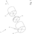
- Figure 1 shows an exhaust gas treatment device 1 according to the invention for arrangement in an exhaust system of a motor vehicle.
- a catalytic converter 2 with a heating disk 3 arranged upstream in the exhaust gas flow direction A is arranged in a housing 4.
- Electrical connections 5 can be provided on the housing 4 so that the heating disk 3 arranged in the housing 4 can be supplied with current.
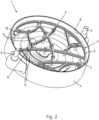
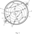
- Figure 2 and 3 show a perspective view and a front view of the heating disc 3 in the housing 4.
- the heating disc 3 is arranged upstream of a holder 6 according to the invention in the exhaust gas flow direction A.
- the holder 6 itself is disc-shaped with a grid-like structure.
- An outer peripheral frame or outer peripheral contour 7 of the holder 6 is coupled to an inner surface 8 of the housing 4. This can be done, for example, by soldering or welding.
- Individual spokes 9 then extend inwardly in the radial direction R from the outer peripheral contour 7 or ring, forming a grid-like structure.
- the spokes 9 themselves each extend in a curved or arched manner. In this embodiment, the spokes 9 are distributed irregularly relative to one another. Preferably, two adjacent or adjacent spokes 9 extend in opposite directions.
- the cross-sectional area of the holder 6 thus essentially covers the cross-sectional area of the inner surface 8 of the housing 4.
- recesses are provided between the spokes 9 or the grid-like structure of the holder 6, so that preferably more than 80%, in particular more than 85%, particularly preferably more than 90%, and most preferably more than 95% of the cross-sectional area is available for the exhaust gas to flow through.
- the holder 6 has a negligible effect on the flow resistance of the exhaust gas flowing through the exhaust gas treatment device 1.
- the heating disc 3 has a corresponding distance 10 from the inner surface 8 of the housing 4. The thermal expansion of the heating disc 3 therefore does not lead to the heating disc 3 coming into contact with the housing 4 in the radial direction R, which would result in an electrical short circuit.
- Attachment points 11 are then arranged on the individual spokes 9. These attachment points 11 have a spacer 12, which is in particular a ceramic sleeve.
- the heating disc 3 is then coupled to the holder 6 itself via the spacer 12.
- three attachment points 11 are formed on a spoke 9.
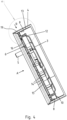
- Figure 4 shows a longitudinal section view according to Figure 3 . It can be seen that an insert plate 13 is arranged in the housing 4 itself, which is spaced apart in the radial direction R from the actual inner surface 8 of the housing 4. Thus, the holder 6 in this case is coupled to the inner surface 8 of the insert plate 13. This results in an air gap 19 for thermal insulation.
- the insert plate 13 is preferably designed as a sleeve. What in Figure 4 shown is that the holder 6 itself is designed in three layers. This has two in the axial direction, outer retaining plates 14 and a spacer plate 15 located in the middle. This achieves the following inventive effect.
- the spacers 12 in the form of ceramic sleeves have a collar 16 located at the top.
- the collar 16 is arranged in a corresponding opening of the spacer plate 15 and then positively fixed in position by a retaining plate arranged upstream and downstream in the exhaust gas flow direction A.
- the respective spacer 12 or the respective ceramic sleeve is positively fixed in position on the holder 6.
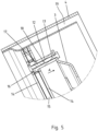
- the individual layers can be materially coupled to one another. This is particularly shown in the enlarged view according to Figure 5 This is clear again.
- the heating disc 3 is then positively attached to an axial end of a spacer 12 using a fastening pin 17 or a bolt, and is positively fixed in position via the fastening pin 17.
- Fastening pins 17 are inserted from two sides, which are coupled together at a central coupling point 18, for example, by resistance spot welding.
- the fastening pin 16 on the holder 6 side only makes contact with the spacer 12, which is electrically insulated. Thus, no electrically conductive connection is established between the heating disc 3 and the spacer 12.
- Figure 6 shows a sectional view through a further design variant.
- a holder 6 is arranged upstream of the heating disc 3 and another holder 6 is arranged downstream of the heating disc.
- the heating disc 3 itself is formed from wave-shaped sheet metal layers. In a top view or as seen from the exhaust gas flow, this results in a honeycomb-like structure.
- the upstream and downstream holders 6 also provide this honeycomb-like structure with strength in the radial direction R.
- Spacers 12 are then arranged between the holders 6.
- the heating disc 3 is then arranged on the spacers 12 themselves with an axial spacing 10 in each case.
- a fastening pin 17 extends through the spacers 12 and couples the opposite holders 6 in a form-fitting manner.
- the fastening pin 17 can then be spot-welded or soldered to the holders 6, for example.
- the spacers 12 each have a collar 16, so that the heating disc 3 is positively fixed in position between the collars 16 and is thus arranged in the exhaust gas treatment device in particular in an electrically insulated manner from the holders 6.
Landscapes
- Engineering & Computer Science (AREA)
- Chemical & Material Sciences (AREA)
- Chemical Kinetics & Catalysis (AREA)
- Combustion & Propulsion (AREA)
- General Engineering & Computer Science (AREA)
- Mechanical Engineering (AREA)
- Health & Medical Sciences (AREA)
- Toxicology (AREA)
- Biomedical Technology (AREA)
- Environmental & Geological Engineering (AREA)
- Analytical Chemistry (AREA)
- General Chemical & Material Sciences (AREA)
- Oil, Petroleum & Natural Gas (AREA)
- Exhaust Gas After Treatment (AREA)
- Resistance Heating (AREA)
Description
- Die vorliegende Erfindung betrifft eine Abgasbehandlungsvorrichtung in einem Abgasstrang eines Kraftfahrzeuges gemäß den Merkmalen im Oberbegriff von Anspruch 1.
- Um der Gesetzgebung und Markt- bzw. Kundenerwartungen zu entsprechen, werden Verbrennungsmotoren heutzutage auf höchste Effizienz getrimmt und produzieren so wenig Abwärme wie möglich.
- Im Widerspruch dazu steht eine schnelle Aufheizung der Abgaskomponenten nach dem Kaltstart und das Halten dieses Temperaturbereichs während den gängigen Testzyklen, um optimale Reaktionsbedingungen für die Umsetzung von schädlichen Abgasbestandteilen in nicht schädliche Elemente zu gewährleisten.
- Dieser Light-Off beginnt bei Katalysatoren ab ca. 180°C, die Reaktionsgeschwindigkeit steigt mit der Temperatur. Da kommende Zulassungsbeschränkungen die Abgaszusammensetzung direkt nach Kaltstart beurteilen, sollte die Light-Off Temperatur schnellstmöglich erreicht werden.
- Hierzu werden Heizelemente eingesetzt, welche ein aktives Thermomanagement der Abgasanlage innerhalb gewisser Grenzen erlauben. Diese sind aktuell meist aus Dünnblechwabenstrukturen (Finnenstrukturen) spiralförmig gewickelt. Die Trennung der Leiter (Wabenstränge) wird durch einen Luftspalt sichergestellt. Durch Hochtemperaturlöten wird der Gesamtaufbau versteift. Die elektrische Isolierung der gesamten Heizmatrix erfolgt meistens über Keramikstifte (Support-Pins), wobei diese in den Katalysatorkörper eingeschoben werden.
- Aus der vorangemeldeten, jedoch nachveröffentlichten
EP 3 964 696 A1 ist ein Abgashalter für eine Abgasanlage bekannt, bei dem im Längsschnitt wellenförmig verlaufende Speichen, beide umlaufend regelmäßig angeordnet sind. - Aus der
DE 20 2020 104 976 U1 ist ein elektrisches Heizaggregat bekannt, bei dem mechanisch angeschlossene Trägerstruktur gegenüber einer Einfassung elektrisch isoliert angeordnet ist. - Aufgabe der vorliegenden Erfindung ist es, ausgehend vom Stand der Technik eine Heizvorrichtung in einem Abgasstrang anzuordnen, welche kostengünstig und einfach produzierbar ist, gleichzeitig eine hoch effiziente Heizleistung bereitstellt und insbesondere eine hohe thermische Resistenz aufweist.
- Die zuvor genannte Aufgabe wird erfindungsgemäß mit einer Abgasbehandlungsvorrichtung zur Anordnung in einem Abgasstrang eines Kraftfahrzeuges mit den Merkmalen im Anspruch 1 gelöst.
- Vorteilhafte Ausgestaltungsvarianten sind Gegenstand der abhängigen Ansprüche.
- Die vorliegende Erfindung betrifft eine Abgasbehandlungsvorrichtung zur Anordnung in einem Abgasstrang eines Kraftfahrzeuges. Dieses Kraftfahrzeug weist einen Verbrennungsmotor auf. Der Verbrennungsmotor kann beispielsweise ein Diesel-oder Ottomotor sein. Auch kann es sich um ein Hybridkraftfahrzeug handeln, welches einen zusätzliches Verbrennungsmotor aufweist. Es handelt sich bei der Abgasbehandlungsvorrichtung somit um eine Abgasnachbehandlungsvorrichtung.
- Das Kraftfahrzeug weist einen Abgasstrang auf. In dem Abgasstrang ist eine Abgasnachbehandlungskomponente, insbesondere in Form eines Katalysators angeordnet. Dem Katalysator ist in Abgasströmungsrichtung in dem Abgasstrang vor- bzw. nachgeschaltet eine Heizscheibe. Die Heizscheibe dient zur elektrischen externen Aufheizung des Katalysators, beispielsweise während der Kaltstartphase.
- Die Heizscheibe selbst ist durch ein flächiges Heizelement ausgebildet. Dies kann eine Heizwendel oder auch eine Wabenanordnung sein. Insbesondere ist das Heizelement eine elektrische Widerstandsheizung, die sich beim Beaufschlagen mit einem elektrischen Strom in kürzester Zeit aufheizt und dann über Strahlung und/oder Konvektion den Katalysator aufheizt. Das Heizelement bzw. die Heizscheibe kann auch aus einem Lochblech oder einem Drahtgewebe bzw. Drahtgeflecht hergestellt sein. Die Heizscheibe selbst muss nicht als einteiliger flächiger Körper ausgebildet sein, es kann auch ein spiralförmig gewundener Heizleiter sein, der dann jedoch in der Ebene einer Scheibe angeordnet ist. Der Heizleiter selbst ist dann entweder massiv ausgebildet oder kann auch aus einem porösen Material, beispielsweise aus einem Drahtgeflecht ausgebildet sein. Bei dem Drahtgeflecht handelt es sich um ein Drahtgewebe bzw. ein Lochblech. Dies bietet weiterhin den Vorteil, dass das Heizelement nicht nur umströmt werden kann, sondern auch durch die jeweilige Porösität des Heizleiters hindurchgeströmt werden kann.
- Damit das elektrische Heizelement in dem Abgasstrang angeordnet ist, ist erfindungsgemäß ein Halter vorgesehen. Das elektrische Heizelement ist mit dem Halter gekoppelt. Der Halter erstreckt sich mindestens über die Querschnittsfläche des Heizelementes.
- Erfindungsgemäß ist der Halter radial umlaufend größer ausgebildet als das Heizelement selber. Der Halter kann somit in einem Gehäuse der Abgasnachbehandlungsvorrichtung angeordnet werden, insbesondere mit einer Innenmantelfläche gekoppelt werden. Der Halter hält dann das Heizelement von der Innenmantelfläche des Gehäuses beabstandet, bezogen auf die Radialrichtung.
- Damit der Halter auch axial beabstandet das Heizelement selbst halten kann, ist der Halter selbst als scheibenförmiges, flächiges Element ausgebildet. Damit jedoch das Abgas durch den Halter hindurchströmen kann, ist der Halter selbst nicht als dichte Scheibe ausgebildet, sondern weist eine spinnennetzartige bzw. gitterartige Struktur auf. Diese Struktur ist erfindungsgemäß dadurch ausgebildet, dass die auf die Radialrichtung bezogene Innenfläche des Halters bzw. der Scheibenform des Halters, durch bogenförmig verlaufende miteinander gekoppelte Speichen ausgebildet ist. Diese bogenförmigen Speichen folgen dabei einer Splinefunktion bzw. haben einen kurvenförmigen Verlauf. Die Bogenform der einzelnen Speichen bewirkt die besondere thermomechanische Festigkeit des Halters. Mithin werden Ausdehnungen bzw. Kontraktionen aufgrund unterschiedlicher Temperaturbereiche aufgrund der Bogenform bestmöglich kompensiert.
- Die Heizscheibe ist dann über einzelne Koppelpunkte oder Haltepunkte mit dem Halter gekoppelt. Durch die gute thermomechanische Festigkeit erfahren somit die Befestigungspunkte eine nur geringe Positionsänderung aufgrund von Ausdehnungen oder Kontraktionen, was sich wiederum auch auf die thermomechanische Festigkeit des mit dem Halter gekoppelten Heizelement auswirkt.
- Eine Speiche muss im Sinne der Erfindung nicht von einem außen umlaufenden Rahmen oder Kontur radial nach innen zu einer Nabe laufen. Eine Speiche im Sinne der Erfindung ist eine in den Innenbereich verlaufende Verbindung. Eine radiale nach innen verlaufende Orientierung bedeutet nicht geradlinig nach innen verlaufend, sondern dass die Speiche generell eine Orientierung zu einem radial gerichteten Innenraum des scheibenförmigen Körpers aufweist.
- Die Speichen verbinden sich somit zu einem im Wesentlichen unregelmäßigen Stützgitter und ermöglichen es somit, Verbindungspunkte über die gesamte Querschnittsfläche des Heizleiters zu schaffen. Gleichzeitig ist der Strömungswiderstand äußerst gering, da die Speichen, bezogen auf den gesamten Querschnitt des Gehäuses der Abgasnachbehandlungskomponente weniger als 20 %, insbesondere weniger als 15 % und ganz besonders bevorzugt weniger als 10 % der Querschnittsfläche bedecken. In dem Halter sind große Ausschnittsflächen vorhanden, so dass das Abgas nahezu in zu vernachlässigender Weise im Strömungswiderstand gesteigert durch den Halter und das Heizelement strömen kann. Die Zwischenbereiche zwischen den Speichen sind somit strömungsoffen ausgebildet bzw. ausgeschnitten.
- Der Halter kann beispielsweise als Stanzbauteil oder auch als ausgeschnittenes Bauteil durch ein Lasertrennverfahren oder ähnliches aus einem metallischen Werkstoff, insbesondere aus einem abgasresistenten Edelstahlwerkstoff hergestellt sein, insbesondere kommt hier ein ferritischer oder austenitischer Werkstoff zum Einsatz.
- Besonders bevorzugt sind jeweils zwei benachbarte Speichen, die zueinander gegenläufig, bezogen auf die Bogenform, verlaufen. Dies kann die thermische Resistenz aufgrund unterschiedlicher Ausdehnungsverhalten nochmals weiter verbessern.
- Damit nunmehr das Heizelement mit dem Halter gekoppelt ist, sind Abstandshalter vorgesehen. Hierbei handelt es sich insbesondere um Keramikhülsen. Die Keramikhülsen haben den Vorteil, dass diese thermisch resistent und elektrisch nicht leitend ausgebildet sind. Besonders bevorzugt wird dann ein Stift die Keramikhülsen durchgreifend mit dem Halter und dem Heizelement gekoppelt. Somit ist das Heizelement axial beabstandet von dem Halter formschlüssig lagefixiert angeordnet, gleichzeitig auch elektrisch isoliert. Bei Beaufschlagung des Heizelementes mit einem elektrischen Strom kommt es somit nicht zu einem Kurzschluss mit dem Gehäuse der Abgasnachbehandlungskomponente.
- In einer weiteren bevorzugten Ausgestaltungsvariante sind die Stifte, welche auch Befestigungsstifte genannt werden können, unter einer Vorspannung angeordnet. Die Vorspannung wird insbesondere erreicht, indem die Stifte punktgeschweißt werden. Bei Umgebungstemperatur wird somit erreicht, dass während des Schweißvorganges eine hohe thermische Einwirkung stattfindet und die Stifte formschlüssig verschweißt sind. Kühlt nunmehr der Stift ab, kontrahiert sich der Stift und spannt somit Halter und Heizscheibe, gekoppelt über die keramische Abstandshülse vor. Ein loser Sitz, Klappern oder auch thermische Spannung oder Ausdehnungen werden somit sichergehend vermieden.
- Der vorgenannte Effekt kann besonders bevorzugt dadurch verbessert werden, dass zwei Befestigungsstifte von entgegengesetzten Seiten, also aufeinander zugerichtet, eingesetzt werden. Diese Stifte werden dann an den sich berührenden Spitzen miteinander gekoppelt, insbesondere verschweißt. Überschüssiges Material schmilzt auf und die axiale Länge, der sich zwei ergebenden Stifte entspricht dann am Ende des Schweißvorganges dem Abstand von Heizscheibe, Abstandshülse und Halter. Es wird eine Passung hergestellt. Nach dem Schweißvorgang kontrahiert sich das Material, so dass die zwei miteinander gekoppelten Stifte in ihrer Axialrichtung sich kontrahieren und somit die Heizscheibe über den Abstandshalter in Form der Keramikbuchse an den Halter koppeln, wobei die Stifte unter einer Vorspannung bzw. Zugspannung stehen. Bei einem späteren Erwärmen im Betrieb, also Abgas strömt, führt somit eine Ausdehnung der Stifte aufgrund der Vorspannung nicht zu einem Klappern bzw. losen Halten. Die Lebensdauer der Halterung wird somit erhöht.
- Die Speichen selbst sind bevorzugt einstückig und werkstoffeinheitlich in dem Halter ausgebildet.
- Der Halter selbst kann in einer weiter bevorzugten Ausgestaltungsvariante auch selbst mehrlagig ausgebildet sein. Hierbei gibt es dann bevorzugt drei Blechlagen. Zwei äußere Blechlagen sind als jeweiliges Klemmblech oder Halterblech ausgebildet. Eine mittlere Blechlage ist als Distanzblech ausgebildet. Eine jeweilige Keramikhülse kann somit mit einem Bund in eine Öffnung des Distanzbleches eingelegt werden. Ein in Axialrichtung vorgeschaltetes Klemmblech fixiert dann den Bund der Distanzhülse in dem Halter selber. Die einzelnen Lagen können miteinander gekoppelt werden, insbesondere stoffschlüssig, beispielsweise durch einen Lötvorgang oder auch einen Schweißvorgang.
- In einer weiteren bevorzugten Ausgestaltungsvariante ist das Heizelement sandwichartig zwischen zwei Haltern, bezogen auf die Abgasströmungsrichtung, angeordnet. Dies bedeutet, ein Halter ist dem Heizelement in Abgasströmungsrichtung vorgeschaltet und ein weiterer Halter dem Heizelement in Abgasströmungsrichtung nachgeschaltet. Bezogen auf die Axialrichtung ist das Heizelement somit optimal gehalten, selbst bei hohen Strömungsgeschwindigkeiten des durch die Abgasnachbehandlungskomponente strömenden Abgases.
- Weitere Vorteile, Merkmale und Eigenschaften der vorliegenden Erfindung sind Gegenstand der nachfolgenden Beschreibung. Vorteilhafte Ausgestaltungsvarianten werden in schematischen Figuren dargestellt. Diese dienen dem einfachen Verständnis der Erfindung.
- Figur 1
- eine Explosivdarstellung einer erfindungsgemäßen Abgasbehandlungsvorrichtung,
- Figur 2
- eine perspektivische Ansicht auf einen erfindungsgemäßen Halter mit Heizscheibe,
- Figur 3
- eine Draufsicht bzw. Stirnansicht auf einen erfindungsgemäßen Halter mit dahinter liegender Heizscheibe,
- Figur 4
- eine Schnittansicht gemäß
Figur 3 , - Figur 5
- eine Detailansicht aus
Figur 4 und - Figur 6
- eine alternative Ausgestaltungsvariante einer Heizscheibe, welche zwischen zwei Haltern in Abgasströmungsrichtung angeordnet ist.
-
Figur 1 zeigt eine erfindungsgemäße Abgasbehandlungvorrichtung 1 zur Anordnung in einem Abgasstrang eines Kraftfahrzeuges. Hierzu ist ein Katalysator 2 mit in einer in Abgasströmungsrichtung A vorgelagerten Heizscheibe 3 in einem Gehäuse 4 angeordnet. An dem Gehäuse 4 können elektrische Anschlüsse 5 vorhanden sein, so dass die in dem Gehäuse 4 geordnete Heizscheibe 3 mit Strom beaufschlagbar ist. -
Figur 2 und3 zeigen eine perspektivische Ansicht sowie eine Stirnansicht auf die Heizscheibe 3 in dem Gehäuse 4. Die Heizscheibe 3 ist in Abgasströmungsrichtung A ein erfindungsgemäßer Halter 6 vorgelagert. - Der Halter 6 ist selbst scheibenförmig mit einer gitterartigen Struktur ausgebildet. Ein außen umlaufender Rahmen bzw. eine außen umlaufende Kontur 7 des Halters 6 ist mit einer Innenmantelfläche 8 des Gehäuses 4 gekoppelt. Dies kann beispielsweise über Löten oder Schweißen erfolgen. Von der außen umlaufenden Kontur 7 bzw. Ring erstrecken sich dann in Radialrichtung R nach innen bezogen einzelne Speichen 9, welche eine gitterartige Struktur ausbilden. Die Speichen 9 selbst verlaufen jeweils gekrümmt bzw. bogenförmig. Die Speichen 9 sind in dieser Ausgestaltungsvariante unregelmäßig zueinander verteilt. Bevorzugt sind jeweils zwei benachbarte oder angrenzende Speichen 9 gegenläufig verlaufend.
- Die Querschnittsfläche des Halters 6 überdeckt somit im Wesentlichen die Querschnittsfläche der Innenmantelfläche 8 des Gehäuses 4. Zwischen den Speichen 9 bzw. der gitterartigen Struktur des Halters 6 sind jedoch Aussparungen vorgesehen, so dass bevorzugt mehr als 80, insbesondere mehr als 85, besonders bevorzugt mehr als 90 und ganz besonders bevorzugt mehr als 95 % der Querschnittsfläche zum Durchströmen des Abgases bereitgestellt werden. Mithin wirkt sich der Halter 6 in zu vernachlässigender Weise auf den Strömungswiderstand des durch die Abgasbehandlungsvorrichtung 1 strömenden Abgases aus.
- Die Heizscheibe 3 weist einen entsprechenden Abstand 10 zu der Innenmantelfläche 8 des Gehäuses 4 auf. Die thermische Ausdehnung der Heizscheibe 3 führen somit nicht dazu, dass die Heizscheibe 3 in Radialrichtung R einen Kontakt mit dem Gehäuse 4 hätte, so dass es zu einem elektrischen Kurzschluss käme.
- Auf den einzelnen Speichen 9 sind sodann Befestigungspunkte 11 angeordnet. Diese Befestigungspunkte 11 weisen einen Abstandhalter 12 auf, welcher insbesondere eine Keramikhülse ist. Über den Abstandhalter 12 ist dann die Heizscheibe 3 mit dem Halter 6 selber gekoppelt. Bevorzugt sind auf einer Speiche 9 drei Befestigungspunkte 11 ausgebildet. Somit kann über den gesamten Verlauf der Speiche 9 und unter Prüfung der thermischen Ausdehnung ein optimales Kompensationsverhältnis von gegebener Haltefunktion und Kompensation der thermischen Ausdehnung erreicht werden.
-
Figur 4 zeigt eine Längsschnittansicht gemäßFigur 3 . Hierbei ist zu erkennen, dass ein Einsatzblech 13 in dem Gehäuse 4 selbst angeordnet ist, welches in Radialrichtung R beabstandet zu der eigentlichen Innenmantelfläche 8 des Gehäuses 4 ist. Somit ist der Halter 6 in diesem Falle an der Innenmantelfläche 8 des Einsatzbleches 13 gekoppelt. Es ergibt sich ein Luftspalt 19 zur thermischen Isolierung. Das Einsatzblech 13 ist bevorzugt als Hülse ausgebildet. Was inFigur 4 dargestellt ist, ist, dass der Halter 6 selbst dreilagig ausgebildet ist. Dieser weist zwei in Axialrichtung außenliegende Haltebleche 14 auf sowie ein der Mitte liegende Distanzblech 15. Hierdurch wird folgender erfindungsgemäßer Effekt erreicht. Die Abstandhalter 12 in Form von Keramikhülsen weisen einen oben liegenden Bund 16 auf. Der Bund 16 wird in eine entsprechende Öffnung des Distanzbleches 15 angeordnet und sodann durch einen in Abgasströmungsrichtung A vor- und nachgelagertes Halteblech formschlüssig lagefixiert. Damit ist der jeweilige Abstandhalter 12 bzw. die jeweilige Keramikhülse an dem Halter 6 formschlüssig lagefixiert. Die einzelnen Lagen können untereinander stoffschlüssig gekoppelt sein. Insbesondere wird dies in der Vergrößerungsansicht gemäßFigur 5 nochmals deutlich. Nunmehr wird dann die Heizscheibe 3 mit einem Befestigungsstift 17 bzw. einem Bolzen formschlüssig an ein axiales Ende eines Abstandhalters 12 angelegt und über den Befestigungsstift 17 formschlüssig lagefixiert. Hier werden von zwei Seiten Befestigungsstifte 17 eingesetzt, welche in einem mittleren Koppelpunkt 18, beispielsweise durch Widerstandspunktschweißen miteinander gekoppelt sind. Der Befestigungsstift 16 auf Seiten des Halters 6 hat ausschließlich Anlagenkontakt an dem Abstandhalter 12, welche elektrische isoliert ist. Somit kommt keine stromleitende Verbindung von Heizscheibe 3 zu Abstandhalter 12 zustande. -
Figur 6 zeigt eine Schnittansicht durch eine weitere Ausgestaltungsvariante. Hier ist in Abgasströmungsrichtung 1 ein Halter 6 der Heizscheibe 3 vorgeschaltet und ein weiterer Halter 6 der Heizscheibe nachgeschaltet. Die Heizscheibe 3 selbst ist durch wellenförmig ausgebildete Blechlagen ausgebildet. In Draufsicht bzw. in Sicht der Abgasströmung ergibt sich somit eine wabenartige Struktur. Durch die vor- und nachgelagerten Halter 6 wird diese wabenförmige Struktur auch in Radialrichtung R mit Festigkeit ausgestattet. Es dann wiederum Abstandhalter 12 zwischen den Haltern 6 angeordnet. Auf den Abstandhaltern 12 selber ist dann die Heizscheibe 3 mit einem jeweils axialen Abstand 10 angeordnet. Ein Befestigungsstift 17 durchgreift die Abstandhalter 12 und koppelt die gegenüberliegenden Halter 6 formschlüssig. Der Befestigungsstift 17 kann dann mit den Haltern 6 jeweils beispielsweise punktgeschweißt oder verlötet werden. Die Abstandshalter 12 weisen jeweils einen Bund 16 auf, so dass die Heizscheibe 3 zwischen den Bunden 16 formschlüssig lagefixiert ist und damit insbesondere elektrisch isoliert von den Haltern 6 in der Abgasbehandlungsvorrichtung angeordnet ist. -
- 1 -
- Abgasbehandlungsvorrichtung
- 2 -
- Katalysator
- 3 -
- Heizscheibe
- 4 -
- Gehäuse
- 5 -
- elektrischer Anschluss
- 6 -
- Halter
- 7 -
- Rahmen/Kontur
- 8 -
- Innenmantelfläche zu 4
- 9 -
- Speiche
- 10 -
- Abstand
- 11 -
- Befestigungspunkt
- 12 -
- Abstandhalter
- 13 -
- Einsatzblech
- 14 -
- Halterblech
- 15 -
- Distanzblech
- 16 -
- Bund
- 17 -
- Befestigungsstift
- 18 -
- Koppelpunkt
- 19 -
- Luftspalt
- R -
- Radialrichtung
- A -
- Abgasströmungsrichtung
Claims (11)
- Abgasbehandlungsvorrichtung (1) zur Anordnung in einem Abgasstrang eines Kraftfahrzeuges, aufweisend eine Heizscheibe (3), welche einer Abgasnachbehandlungskomponente, insbesondere einem Katalysator (2) zugeordnet ist, wobei die Heizscheibe (3) durch ein flächiges Heizelement und einen mit diesem gekoppelten Halter (6) ausgebildet ist, dadurch gekennzeichnet, dass der Halter (6) sich über die Querschnittsfläche des Heizelementes erstreckt und der Halter (6) selbst als flächiges, scheibenförmiges Element mit einer gitterartigen Struktur ausgebildet ist, wobei der Halter (6) in einem Gehäuse (4) der Abgasnachbehandlungskomponente mit einer Innenmantelfläche (8) gekoppelt ist, wobei der Halter (6) radial umlaufend größer ausgebildet ist als das Heizelement und eine gitterartige Struktur des Halters (6) durch unregelmäßig miteinander verbundene bogenförmige Speichen (9) ausgebildet ist, wobei die Heizscheibe (3) über Befestigungspunkte (11) mit dem Halter (6) gekoppelt ist, wobei die Speichen (9), bezogen auf den gesamten Querschnitt des Gehäuses (4) der Abgasnachbehandlungskomponente weniger als 20 % der Querschnittsfläche bedecken.
- Abgasbehandlungsvorrichtung (1) nach Anspruch 1, dadurch gekennzeichnet, dass der Halter (6) aus einem metallischen Werkstoff ausgebildet ist, insbesondere als Stanzteil oder ausgeschnitten.
- Abgasbehandlungsvorrichtung (1) nach Anspruch 1 oder 2, dadurch gekennzeichnet, dass zwei benachbarte bogenförmige Speichen (9) gegenläufige Bogenformen aufweisen.
- Abgasbehandlungsvorrichtung (1) nach einem der vorangehenden Ansprüche, dadurch gekennzeichnet, dass an einer bogenförmigen Speiche (9) mindestens ein, bevorzugt zwei, ganz besonders bevorzugt drei Befestigungspunkte (11) zur Koppelung mit dem Heizelement vorgesehen sind.
- Abgasbehandlungsvorrichtung (1) nach einem der vorangehenden Ansprüche, dadurch gekennzeichnet, dass das Heizelement eine wabenartige Struktur aufweist und insbesondere als elektrisch betriebenes Heizelement ausgebildet ist.
- Abgasbehandlungsvorrichtung (1) nach einem der vorangehenden Ansprüche, dadurch gekennzeichnet, dass das Heizelement aus gewelltem Folienwerkstoff ausgebildet ist oder dass ein Heizleiter des Heizelementes aus einem Lochblech oder Drahtgeflecht ausgebildet ist, wobei das Lochblech bzw. Drahtgeflecht bevorzugt spiralförmig gewickelt ist.
- Abgasbehandlungsvorrichtung (1) nach einem der vorangehenden Ansprüche, dadurch gekennzeichnet, dass zwischen Heizelement und Halter (6) elektrisch isolierende, thermisch resistente Koppelungsmittel angeordnet sind, insbesondere Keramikbuchsen.
- Abgasbehandlungsvorrichtung (1) nach einem der vorangehenden Ansprüche, dadurch gekennzeichnet, dass zwei Halter (6) das Heizelement sandwichartig zwischen sich aufnehmen.
- Abgasbehandlungsvorrichtung (1) nach einem der vorangehenden Ansprüche, dadurch gekennzeichnet, dass als Koppelungsmittel eine Abstandsbuchse ausgebildet ist, sowie ein die Abstandsbuchse durchgreifender Stift, wobei die Abstandsbuchse elektrisch isoliert ausgebildet ist.
- Abgasbehandlungsvorrichtung (1) nach Anspruch 9, dadurch gekennzeichnet, dass in einem Koppelungsmittel zwei gegenläufig aufeinander zu zeigende Bestigungsstifte (17) angeordnet sind, welche an ihren Spitzen miteinander gekoppelt sind und bevorzugt stehen die Befestigungsstifte (17) unter Zugspannung.
- Abgasbehandlungsvorrichtung (1) nach einem der vorangehenden Ansprüche, dadurch gekennzeichnet, dass der Halter (6) mit einer außen zumindest abschnittsweise, insbesondere vollständig umlaufenden Kontur (7) in einem Gehäuse (4) der Abgasnachbehandlungskomponente gekoppelt ist, wobei die Speichen (9) dann einstückig und werkstoffeinheitlich von der Kontur (7) radial orientiert nach innen angebunden sind und untereinander gekoppelt sind.
Applications Claiming Priority (1)
| Application Number | Priority Date | Filing Date | Title |
|---|---|---|---|
| DE102021103283.0A DE102021103283A1 (de) | 2021-02-11 | 2021-02-11 | Halter für eine elektrische Heizscheibe in eine Abgasnachbehandlungsvorrichtung |
Publications (2)
| Publication Number | Publication Date |
|---|---|
| EP4047194A1 EP4047194A1 (de) | 2022-08-24 |
| EP4047194B1 true EP4047194B1 (de) | 2025-05-14 |
Family
ID=80222145
Family Applications (1)
| Application Number | Title | Priority Date | Filing Date |
|---|---|---|---|
| EP22155402.5A Active EP4047194B1 (de) | 2021-02-11 | 2022-02-07 | Halter für eine elektrische heizscheibe in einer abgasnachbehandlungsvorrichtung |
Country Status (5)
| Country | Link |
|---|---|
| US (1) | US11795850B2 (de) |
| EP (1) | EP4047194B1 (de) |
| JP (1) | JP2022123833A (de) |
| CN (1) | CN114922717A (de) |
| DE (1) | DE102021103283A1 (de) |
Families Citing this family (5)
| Publication number | Priority date | Publication date | Assignee | Title |
|---|---|---|---|---|
| EP4060169B1 (de) * | 2021-03-15 | 2024-04-03 | Purem GmbH | Abgasheizer |
| DE102021205198A1 (de) | 2021-05-20 | 2022-11-24 | Vitesco Technologies GmbH | Vorrichtung zur Erwärmung eines Abgasstroms |
| DE102022121595B3 (de) * | 2022-08-25 | 2023-10-26 | Tenneco Gmbh | Aufnahme für Heizwiderstand |
| DE102023106514A1 (de) * | 2023-03-15 | 2024-09-19 | Oberland Mangold Gmbh | Elektrisches Widerstands-Heizeinheit sowie damit ausgestattetes Rauchgas-Behandlungsmodul |
| DE102024102588A1 (de) * | 2024-01-30 | 2025-07-31 | Emitec Technologies GmbH | Stützstruktur für eine Abgasnachbehandlungseinheit sowie Vorrichtung mit einem Wabenköper und einer Stützstruktur |
Citations (9)
| Publication number | Priority date | Publication date | Assignee | Title |
|---|---|---|---|---|
| WO1992002714A1 (de) | 1990-07-30 | 1992-02-20 | Emitec Gesellschaft Für Emissionstechnologie Mbh | Elektrisch beheizbarer wabenkörper, insbesondere katalysator-trägerkörper, mit inneren tragstrukturen |
| WO1997013057A1 (de) | 1995-10-02 | 1997-04-10 | Emitec Gesellschaft Für Emissionstechnologie Mbh | Elektrisch beheizbarer, in teilbereiche unterteilter wabenkörper mit verbindungsstegen |
| WO2010122005A1 (de) | 2009-04-22 | 2010-10-28 | Emitec Gesellschaft Für Emissionstechnologie Mbh | Mehrstufig beheizbarer wabenkörper |
| WO2018080578A1 (en) | 2016-10-31 | 2018-05-03 | Watlow Electric Manufacturing Company | High power density insulated exhaust heating system |
| DE112019001864T5 (de) | 2018-04-11 | 2020-12-31 | Faurecia Systemes D'echappement | Abgasleitung, Vorrichtung zur Abgasreinigung und Verfahren zur Herstellung der Reinigungsvorrichtung |
| DE102019121382A1 (de) | 2019-08-07 | 2021-02-11 | Faurecia Emissions Control Technologies, Germany Gmbh | Abgasbehandlungseinrichtung und Fahrzeug |
| EP3825528A1 (de) | 2019-11-22 | 2021-05-26 | Eberspächer Exhaust Technology GmbH | Abgasheizer |
| WO2022043207A1 (de) | 2020-08-28 | 2022-03-03 | Hjs Emission Technology Gmbh & Co. Kg | Elektrisches heizaggregat |
| EP3964696A1 (de) | 2020-09-08 | 2022-03-09 | Purem GmbH | Abgasheizer |
Family Cites Families (16)
| Publication number | Priority date | Publication date | Assignee | Title |
|---|---|---|---|---|
| JPS6078918U (ja) * | 1983-11-08 | 1985-06-01 | トヨタ自動車株式会社 | デイ−ゼルパテイキユレ−ト浄化装置 |
| US4548625A (en) * | 1984-07-11 | 1985-10-22 | Toyota Jidosha Kabushiki Kaisha | Exhaust gas cleaning device for diesel engines |
| US4723973A (en) * | 1985-09-28 | 1988-02-09 | Nippondenso Co., Ltd. | Purifying apparatus of a particulate trap-type for collecting particulates in exhaust gas from an engine |
| JP3142717B2 (ja) * | 1994-06-16 | 2001-03-07 | 日本碍子株式会社 | ヒーターユニット及び触媒コンバーター |
| JPH08326526A (ja) * | 1995-05-30 | 1996-12-10 | Nippon Steel Corp | 電気加熱式金属触媒担体 |
| JP3239755B2 (ja) * | 1996-05-28 | 2001-12-17 | トヨタ自動車株式会社 | ハニカム体を用いた触媒装置 |
| JP3544471B2 (ja) * | 1998-05-12 | 2004-07-21 | 日本碍子株式会社 | 六角セルハニカム構造体とその把持方法 |
| US5953909A (en) * | 1998-08-03 | 1999-09-21 | Waltrip, Iii; Owen R. | Combustor for unspent exhaust from an internal combustion engine |
| CN2718228Y (zh) * | 2004-07-16 | 2005-08-17 | 上海比亚迪有限公司 | 可电加热汽车尾气催化净化器 |
| JP2009043470A (ja) * | 2007-08-07 | 2009-02-26 | Nissan Motor Co Ltd | 電気加熱体、排気システム、内燃機関、燃料電池システム、暖房システム |
| FR3065027B1 (fr) * | 2017-04-07 | 2019-11-29 | Faurecia Systemes D'echappement | Dispositif de purification des gaz d'echappement d'un vehicule et procede de pilotage correspondant |
| JP7185409B2 (ja) * | 2018-03-08 | 2022-12-07 | 日鉄ケミカル&マテリアル株式会社 | 加熱ユニット |
| DE102019101679A1 (de) * | 2019-01-24 | 2020-07-30 | Eberspächer Exhaust Technology GmbH & Co. KG | Abgasheizelement |
| GB201904232D0 (en) * | 2019-03-27 | 2019-05-08 | Johnson Matthey Plc | Apparatus, vehicle and method |
| NO20190635A1 (en) * | 2019-05-21 | 2020-11-23 | Vestlandets Innovasjonsselskap As | A catalytic converter module and a method of enhancing the efficiency of a catalytic converter |
| CN111828145B (zh) * | 2020-06-28 | 2022-04-08 | 亿达天地环保技术股份有限公司 | 用于汽车尾气处理的蜂窝结构体 |
-
2021
- 2021-02-11 DE DE102021103283.0A patent/DE102021103283A1/de active Pending
-
2022
- 2022-01-12 JP JP2022002666A patent/JP2022123833A/ja active Pending
- 2022-02-07 EP EP22155402.5A patent/EP4047194B1/de active Active
- 2022-02-10 US US17/669,041 patent/US11795850B2/en active Active
- 2022-02-11 CN CN202210131230.6A patent/CN114922717A/zh active Pending
Patent Citations (9)
| Publication number | Priority date | Publication date | Assignee | Title |
|---|---|---|---|---|
| WO1992002714A1 (de) | 1990-07-30 | 1992-02-20 | Emitec Gesellschaft Für Emissionstechnologie Mbh | Elektrisch beheizbarer wabenkörper, insbesondere katalysator-trägerkörper, mit inneren tragstrukturen |
| WO1997013057A1 (de) | 1995-10-02 | 1997-04-10 | Emitec Gesellschaft Für Emissionstechnologie Mbh | Elektrisch beheizbarer, in teilbereiche unterteilter wabenkörper mit verbindungsstegen |
| WO2010122005A1 (de) | 2009-04-22 | 2010-10-28 | Emitec Gesellschaft Für Emissionstechnologie Mbh | Mehrstufig beheizbarer wabenkörper |
| WO2018080578A1 (en) | 2016-10-31 | 2018-05-03 | Watlow Electric Manufacturing Company | High power density insulated exhaust heating system |
| DE112019001864T5 (de) | 2018-04-11 | 2020-12-31 | Faurecia Systemes D'echappement | Abgasleitung, Vorrichtung zur Abgasreinigung und Verfahren zur Herstellung der Reinigungsvorrichtung |
| DE102019121382A1 (de) | 2019-08-07 | 2021-02-11 | Faurecia Emissions Control Technologies, Germany Gmbh | Abgasbehandlungseinrichtung und Fahrzeug |
| EP3825528A1 (de) | 2019-11-22 | 2021-05-26 | Eberspächer Exhaust Technology GmbH | Abgasheizer |
| WO2022043207A1 (de) | 2020-08-28 | 2022-03-03 | Hjs Emission Technology Gmbh & Co. Kg | Elektrisches heizaggregat |
| EP3964696A1 (de) | 2020-09-08 | 2022-03-09 | Purem GmbH | Abgasheizer |
Also Published As
| Publication number | Publication date |
|---|---|
| CN114922717A (zh) | 2022-08-19 |
| DE102021103283A1 (de) | 2022-08-11 |
| EP4047194A1 (de) | 2022-08-24 |
| US20220251991A1 (en) | 2022-08-11 |
| US11795850B2 (en) | 2023-10-24 |
| JP2022123833A (ja) | 2022-08-24 |
Similar Documents
| Publication | Publication Date | Title |
|---|---|---|
| EP4047194B1 (de) | Halter für eine elektrische heizscheibe in einer abgasnachbehandlungsvorrichtung | |
| DE102021104117B3 (de) | Halter für ein elektrisches Heizelement in einer Abgasnachbehandlungsvorrichtung | |
| EP4047195A1 (de) | Halter für ein elektrisches heizelement in einer abgasnachbehandlungsvorrichtung | |
| EP2836687B1 (de) | Elektrischer anschluss von mehreren blechlagen eines elektrisch beheizbaren wabenkörpers und zugehöriger wabenkörper | |
| EP3964696B1 (de) | Abgasheizer | |
| DE112020002424T5 (de) | Fahrzeugabgasreinigungsvorrichtung, entsprechendes Herstellungsverfahren, Abgasleitung und Fahrzeug | |
| DE69514251T2 (de) | Elektrisch beheizbarer katalytischer Umwandler für einen Motor | |
| DE102020128185A1 (de) | Abgasheizvorrichtung, dazugehörige Abgasleitung und Fahrzeug | |
| DE202020104976U1 (de) | Elektrisches Heizaggregat zum Einschalten in den Abgasstrang einer Brennkraftmaschine sowie damit ausgerüstetes Abgasreinigungsaggregat | |
| EP2744990B1 (de) | Vorrichtung zur behandlung von abgasen | |
| WO1993007364A1 (de) | Abgaskatalysator | |
| EP0569403A1 (de) | Wabenkörper mit mehreren, gegeneinander abgestützten scheiben. | |
| EP4198274B1 (de) | Heizeinrichtung zum beheizen eines gasstroms | |
| EP3943720B1 (de) | Elektrische heizvorrichtung | |
| DE102022116755A1 (de) | Heizeinrichtung zum Beheizen eines Gasstroms | |
| EP0677141B1 (de) | Katalysator | |
| EP4144965B1 (de) | Abgasheizer | |
| DE102022111864B4 (de) | Heizvorrichtung | |
| EP0853718A1 (de) | Elektrisch beheizbarer wabenkörper mit versteiften stromverteilungsstrukturen | |
| EP3956550B1 (de) | Abgasbehandlungseinrichtung und fahrzeug | |
| EP4141228B1 (de) | Abgasheizer | |
| DE102020118988A1 (de) | Heizvorrichtung für ein Abgassystem eines Kraftfahrzeugs und Abgassystem | |
| DE102022114107B4 (de) | Abgasheizer | |
| DE102021100570B4 (de) | Katalysator mit Heizscheibe | |
| DE102020133033B3 (de) | Aufgewickelter Heizleiter für einen Abgasstrang |
Legal Events
| Date | Code | Title | Description |
|---|---|---|---|
| PUAI | Public reference made under article 153(3) epc to a published international application that has entered the european phase |
Free format text: ORIGINAL CODE: 0009012 |
|
| STAA | Information on the status of an ep patent application or granted ep patent |
Free format text: STATUS: THE APPLICATION HAS BEEN PUBLISHED |
|
| AK | Designated contracting states |
Kind code of ref document: A1 Designated state(s): AL AT BE BG CH CY CZ DE DK EE ES FI FR GB GR HR HU IE IS IT LI LT LU LV MC MK MT NL NO PL PT RO RS SE SI SK SM TR |
|
| STAA | Information on the status of an ep patent application or granted ep patent |
Free format text: STATUS: REQUEST FOR EXAMINATION WAS MADE |
|
| 17P | Request for examination filed |
Effective date: 20220915 |
|
| STAA | Information on the status of an ep patent application or granted ep patent |
Free format text: STATUS: EXAMINATION IS IN PROGRESS |
|
| 17Q | First examination report despatched |
Effective date: 20221221 |
|
| TPAC | Observations filed by third parties |
Free format text: ORIGINAL CODE: EPIDOSNTIPA |
|
| TPAC | Observations filed by third parties |
Free format text: ORIGINAL CODE: EPIDOSNTIPA |
|
| GRAP | Despatch of communication of intention to grant a patent |
Free format text: ORIGINAL CODE: EPIDOSNIGR1 |
|
| STAA | Information on the status of an ep patent application or granted ep patent |
Free format text: STATUS: GRANT OF PATENT IS INTENDED |
|
| INTG | Intention to grant announced |
Effective date: 20250129 |
|
| GRAS | Grant fee paid |
Free format text: ORIGINAL CODE: EPIDOSNIGR3 |
|
| GRAA | (expected) grant |
Free format text: ORIGINAL CODE: 0009210 |
|
| STAA | Information on the status of an ep patent application or granted ep patent |
Free format text: STATUS: THE PATENT HAS BEEN GRANTED |
|
| AK | Designated contracting states |
Kind code of ref document: B1 Designated state(s): AL AT BE BG CH CY CZ DE DK EE ES FI FR GB GR HR HU IE IS IT LI LT LU LV MC MK MT NL NO PL PT RO RS SE SI SK SM TR |
|
| REG | Reference to a national code |
Ref country code: GB Ref legal event code: FG4D Free format text: NOT ENGLISH |
|
| REG | Reference to a national code |
Ref country code: CH Ref legal event code: EP |
|
| REG | Reference to a national code |
Ref country code: DE Ref legal event code: R096 Ref document number: 502022003919 Country of ref document: DE |
|
| REG | Reference to a national code |
Ref country code: IE Ref legal event code: FG4D Free format text: LANGUAGE OF EP DOCUMENT: GERMAN |
|
| REG | Reference to a national code |
Ref country code: NL Ref legal event code: MP Effective date: 20250514 |
|
| PG25 | Lapsed in a contracting state [announced via postgrant information from national office to epo] |
Ref country code: PT Free format text: LAPSE BECAUSE OF FAILURE TO SUBMIT A TRANSLATION OF THE DESCRIPTION OR TO PAY THE FEE WITHIN THE PRESCRIBED TIME-LIMIT Effective date: 20250915 Ref country code: ES Free format text: LAPSE BECAUSE OF FAILURE TO SUBMIT A TRANSLATION OF THE DESCRIPTION OR TO PAY THE FEE WITHIN THE PRESCRIBED TIME-LIMIT Effective date: 20250514 Ref country code: FI Free format text: LAPSE BECAUSE OF FAILURE TO SUBMIT A TRANSLATION OF THE DESCRIPTION OR TO PAY THE FEE WITHIN THE PRESCRIBED TIME-LIMIT Effective date: 20250514 |
|
| REG | Reference to a national code |
Ref country code: LT Ref legal event code: MG9D |
|
| PG25 | Lapsed in a contracting state [announced via postgrant information from national office to epo] |
Ref country code: GR Free format text: LAPSE BECAUSE OF FAILURE TO SUBMIT A TRANSLATION OF THE DESCRIPTION OR TO PAY THE FEE WITHIN THE PRESCRIBED TIME-LIMIT Effective date: 20250815 Ref country code: NO Free format text: LAPSE BECAUSE OF FAILURE TO SUBMIT A TRANSLATION OF THE DESCRIPTION OR TO PAY THE FEE WITHIN THE PRESCRIBED TIME-LIMIT Effective date: 20250814 |
|
| PG25 | Lapsed in a contracting state [announced via postgrant information from national office to epo] |
Ref country code: PL Free format text: LAPSE BECAUSE OF FAILURE TO SUBMIT A TRANSLATION OF THE DESCRIPTION OR TO PAY THE FEE WITHIN THE PRESCRIBED TIME-LIMIT Effective date: 20250514 Ref country code: NL Free format text: LAPSE BECAUSE OF FAILURE TO SUBMIT A TRANSLATION OF THE DESCRIPTION OR TO PAY THE FEE WITHIN THE PRESCRIBED TIME-LIMIT Effective date: 20250514 |
|
| PG25 | Lapsed in a contracting state [announced via postgrant information from national office to epo] |
Ref country code: BG Free format text: LAPSE BECAUSE OF FAILURE TO SUBMIT A TRANSLATION OF THE DESCRIPTION OR TO PAY THE FEE WITHIN THE PRESCRIBED TIME-LIMIT Effective date: 20250514 |
|
| PG25 | Lapsed in a contracting state [announced via postgrant information from national office to epo] |
Ref country code: HR Free format text: LAPSE BECAUSE OF FAILURE TO SUBMIT A TRANSLATION OF THE DESCRIPTION OR TO PAY THE FEE WITHIN THE PRESCRIBED TIME-LIMIT Effective date: 20250514 |
|
| PG25 | Lapsed in a contracting state [announced via postgrant information from national office to epo] |
Ref country code: RS Free format text: LAPSE BECAUSE OF FAILURE TO SUBMIT A TRANSLATION OF THE DESCRIPTION OR TO PAY THE FEE WITHIN THE PRESCRIBED TIME-LIMIT Effective date: 20250814 |
|
| PG25 | Lapsed in a contracting state [announced via postgrant information from national office to epo] |
Ref country code: IS Free format text: LAPSE BECAUSE OF FAILURE TO SUBMIT A TRANSLATION OF THE DESCRIPTION OR TO PAY THE FEE WITHIN THE PRESCRIBED TIME-LIMIT Effective date: 20250914 |
|
| PG25 | Lapsed in a contracting state [announced via postgrant information from national office to epo] |
Ref country code: LV Free format text: LAPSE BECAUSE OF FAILURE TO SUBMIT A TRANSLATION OF THE DESCRIPTION OR TO PAY THE FEE WITHIN THE PRESCRIBED TIME-LIMIT Effective date: 20250514 |
|
| PG25 | Lapsed in a contracting state [announced via postgrant information from national office to epo] |
Ref country code: DK Free format text: LAPSE BECAUSE OF FAILURE TO SUBMIT A TRANSLATION OF THE DESCRIPTION OR TO PAY THE FEE WITHIN THE PRESCRIBED TIME-LIMIT Effective date: 20250514 Ref country code: SM Free format text: LAPSE BECAUSE OF FAILURE TO SUBMIT A TRANSLATION OF THE DESCRIPTION OR TO PAY THE FEE WITHIN THE PRESCRIBED TIME-LIMIT Effective date: 20250514 |
|
| PG25 | Lapsed in a contracting state [announced via postgrant information from national office to epo] |
Ref country code: CZ Free format text: LAPSE BECAUSE OF FAILURE TO SUBMIT A TRANSLATION OF THE DESCRIPTION OR TO PAY THE FEE WITHIN THE PRESCRIBED TIME-LIMIT Effective date: 20250514 |
|
| REG | Reference to a national code |
Ref country code: DE Ref legal event code: R026 Ref document number: 502022003919 Country of ref document: DE |
|
| PG25 | Lapsed in a contracting state [announced via postgrant information from national office to epo] |
Ref country code: EE Free format text: LAPSE BECAUSE OF FAILURE TO SUBMIT A TRANSLATION OF THE DESCRIPTION OR TO PAY THE FEE WITHIN THE PRESCRIBED TIME-LIMIT Effective date: 20250514 |
|
| PG25 | Lapsed in a contracting state [announced via postgrant information from national office to epo] |
Ref country code: SK Free format text: LAPSE BECAUSE OF FAILURE TO SUBMIT A TRANSLATION OF THE DESCRIPTION OR TO PAY THE FEE WITHIN THE PRESCRIBED TIME-LIMIT Effective date: 20250514 |
|
| PG25 | Lapsed in a contracting state [announced via postgrant information from national office to epo] |
Ref country code: IT Free format text: LAPSE BECAUSE OF FAILURE TO SUBMIT A TRANSLATION OF THE DESCRIPTION OR TO PAY THE FEE WITHIN THE PRESCRIBED TIME-LIMIT Effective date: 20250514 |
|
| PLBI | Opposition filed |
Free format text: ORIGINAL CODE: 0009260 |
|
| REG | Reference to a national code |
Ref country code: CH Ref legal event code: L10 Free format text: ST27 STATUS EVENT CODE: U-0-0-L10-L00 (AS PROVIDED BY THE NATIONAL OFFICE) Effective date: 20260204 |
|
| PLAX | Notice of opposition and request to file observation + time limit sent |
Free format text: ORIGINAL CODE: EPIDOSNOBS2 |
|
| 26 | Opposition filed |
Opponent name: EMITEC TECHNOLOGIES GMBH Effective date: 20260122 |
|
| PGFP | Annual fee paid to national office [announced via postgrant information from national office to epo] |
Ref country code: DE Payment date: 20260224 Year of fee payment: 5 |
|
| PGFP | Annual fee paid to national office [announced via postgrant information from national office to epo] |
Ref country code: AT Payment date: 20260301 Year of fee payment: 5 |