EP4046903B1 - Verfahren und vorrichtung zum überborden eines verbundenen länglichen flexiblen artikels aus einem schiff - Google Patents
Verfahren und vorrichtung zum überborden eines verbundenen länglichen flexiblen artikels aus einem schiff Download PDFInfo
- Publication number
- EP4046903B1 EP4046903B1 EP22155523.8A EP22155523A EP4046903B1 EP 4046903 B1 EP4046903 B1 EP 4046903B1 EP 22155523 A EP22155523 A EP 22155523A EP 4046903 B1 EP4046903 B1 EP 4046903B1
- Authority
- EP
- European Patent Office
- Prior art keywords
- article
- length
- overboarding
- vessel
- joint
- Prior art date
- Legal status (The legal status is an assumption and is not a legal conclusion. Google has not performed a legal analysis and makes no representation as to the accuracy of the status listed.)
- Active
Links
Images






Classifications
-
- B—PERFORMING OPERATIONS; TRANSPORTING
- B63—SHIPS OR OTHER WATERBORNE VESSELS; RELATED EQUIPMENT
- B63B—SHIPS OR OTHER WATERBORNE VESSELS; EQUIPMENT FOR SHIPPING
- B63B35/00—Vessels or similar floating structures specially adapted for specific purposes and not otherwise provided for
- B63B35/04—Cable-laying vessels
-
- B—PERFORMING OPERATIONS; TRANSPORTING
- B63—SHIPS OR OTHER WATERBORNE VESSELS; RELATED EQUIPMENT
- B63B—SHIPS OR OTHER WATERBORNE VESSELS; EQUIPMENT FOR SHIPPING
- B63B35/00—Vessels or similar floating structures specially adapted for specific purposes and not otherwise provided for
- B63B35/03—Pipe-laying vessels
-
- F—MECHANICAL ENGINEERING; LIGHTING; HEATING; WEAPONS; BLASTING
- F16—ENGINEERING ELEMENTS AND UNITS; GENERAL MEASURES FOR PRODUCING AND MAINTAINING EFFECTIVE FUNCTIONING OF MACHINES OR INSTALLATIONS; THERMAL INSULATION IN GENERAL
- F16L—PIPES; JOINTS OR FITTINGS FOR PIPES; SUPPORTS FOR PIPES, CABLES OR PROTECTIVE TUBING; MEANS FOR THERMAL INSULATION IN GENERAL
- F16L1/00—Laying or reclaiming pipes; Repairing or joining pipes on or under water
- F16L1/12—Laying or reclaiming pipes on or under water
- F16L1/16—Laying or reclaiming pipes on or under water on the bottom
- F16L1/18—Laying or reclaiming pipes on or under water on the bottom the pipes being S- or J-shaped and under tension during laying
- F16L1/19—Laying or reclaiming pipes on or under water on the bottom the pipes being S- or J-shaped and under tension during laying the pipes being J-shaped
-
- F—MECHANICAL ENGINEERING; LIGHTING; HEATING; WEAPONS; BLASTING
- F16—ENGINEERING ELEMENTS AND UNITS; GENERAL MEASURES FOR PRODUCING AND MAINTAINING EFFECTIVE FUNCTIONING OF MACHINES OR INSTALLATIONS; THERMAL INSULATION IN GENERAL
- F16L—PIPES; JOINTS OR FITTINGS FOR PIPES; SUPPORTS FOR PIPES, CABLES OR PROTECTIVE TUBING; MEANS FOR THERMAL INSULATION IN GENERAL
- F16L1/00—Laying or reclaiming pipes; Repairing or joining pipes on or under water
- F16L1/12—Laying or reclaiming pipes on or under water
- F16L1/20—Accessories therefor, e.g. floats or weights
- F16L1/202—Accessories therefor, e.g. floats or weights fixed on or to vessels
- F16L1/207—Pipe handling apparatus
Definitions
- the present invention relates to a method for overboarding from a vessel an elongated flexible article that comprises a joint between a first and a second length thereof.
- the invention further relates to a device for carrying out the method, and to a vessel comprising the device.
- an elongated flexible article is meant to comprise articles such as power, electrical, and data communication cables, but also articles like umbilicals, flexible pipelines for instance.
- Cable-laying may for instance be needed when connecting an off-shore wind turbine generator to the electricity network or to an offshore transformer station or any other type of offshore structure, or when connecting other structures that may be at a long distance to each other.
- the invention is not limited to laying cables, and the invention may be used for laying any other flexible elongated article on or in a seabed.
- laying elongated flexible articles such as cables and pipelines on or in a seabed is commonly carried out from so-called cable-laying vessels adapted for this purpose.
- these vessels are fitted with one, two or more storage units for the elongated flexible article, overboarding guide means adapted to smoothly lead the article overboard into the water, article support means defining an article path between the storage unit(s) and the overboarding guide means, and pulling or hauling means for advancing the elongated article along the path.
- the pulling means may comprise a cable-tensioning device to control the tension and/or the pay-out speed of the article as it exits the vessel through the overboarding guide means.
- WO 01/18349 A1 shows a methord and an article for overboarding from a vessel an elongated flexible article, which serve as basis for claims 1 and 10.
- the method and device aim to provide maximum flexibility, in that they allow managing and minimizing the operational risks and loads on the joint and the flexible article, independent of the type of joint or flexible article.
- the invention provides a method in accordance with claim 1.
- a method for overboarding from a vessel an elongated flexible article that comprises a joint between a first and a subsequent second length thereof comprising the steps of:
- the holding means are instrumental in preventing the occurrence of stress in the first and subsequent second article lengths. This allows making the joint between the two (first and second) article lengths, and further prevents stress occurring in this joint during further handling.
- the invented method may be repeated with a third, fourth and more subsequent lengths of the article. It may even be envisaged to join lengths of different articles, as long as their dimensions are such that they may be joined.
- the method according to the invention allows overboarding an elongated flexible article such as a cable from a vessel, wherein the article comprises a joint between a first and a second length thereof, with less risk for damage to the joint or the flexible article itself.
- an embodiment of the method may be provided wherein advancing the first article length is halted when the end of the first length of the article is encountered.
- overboarding the first article length supported by the overboarding guide means and the holding means is carried out until an end of the first length of the article is encountered. If overboarding would continue, the first length of the article could possibly leave or fall off the overboarding guide means. When halting the overboarding of the first length of the article, a part of the first article close to the end may actually be retained by the overboarding guide means, for instance by friction between the article and a support surface of the overboarding guide means.
- a practical embodiment of the invention however provides a method wherein holding the overboarded first length of the article comprises suspending the first length in a hang-off clamp when the end of the first length of the article is encountered to make that part of the first article length that extends between the end and the hang-off clamp to be substantially unloaded.
- the hang-off clamp clamps or holds the first length of the flexible article at one end of the first article, and, at another end may be held by the vessel, for instance by the overboarding guide means or by another support means which is able to take the load of the suspended article.
- a rope may be provided to cover the distance between the clamping and holding positions.
- Suspending the overboarded first length of the article makes that part of the first article length that extends between its end and the position of the hang-off clamp end is substantially unloaded. This further facilitates guiding the end of the first article length to a joining unit for preparing a joint.
- the joint between the first and second lengths of the flexible article may be prepared at any location on the vessel, as long as joining the two lengths of the article is provided by a method wherein the joint is prepared at work deck's height of the vessel.
- Joining of two ends of a flexible article such as an electronic or data-transmission cable is known per se.
- a protective cover may be flexible in that it may accommodate a radius of curvature, but typically is rigid in order to prevent the joint between the two ends from being bent or angled.
- the thus prepared joint is taken up from the joining unit and brought to the overboarding guide means such that part of the second article length is supported by the overboarding guide means and the joint is in a downstream position with respect to the overboarding guide means.
- an embodiment of the method is characterized in that the article is guided over a curved support surface of the overboarding guiding means, preferably a semi-circular support surface.
- a curved surface may for instance be formed by a plurality of rollers that guide the flexible elongated article along the curved surface, or may be formed by a closed surface.
- the radius of the semi-circular support surface in an embodiment is preferably chosen to be equal to or larger than the minimum radius of curvature of the flexible elongated article, such as a cable. Bending the cable along a radius that is smaller than the minimum radius of the cable induces the risk of damage.
- the overboarding guide means may be provided at a height (non-zero) above a work deck of the vessel.
- the height may depend on the particular article that needs to be overboarded but would in circumstances be at least 5 m, more preferably at least 10 m, and more.
- the overboarding guiding means and its support surface for the article lengths may be provided above work deck's height by providing a suitable construction that extends in a substantially vertical direction. At least a part of the elongated flexible article before overboarding then extends in a substantially vertical direction.
- the joint prepared in the joining unit may also be brought up along the above referred height.
- the overboarding guiding means may not be provided above work deck's height by providing the suitable construction.
- the overboarding guiding means may comprise a chute provided at an edge of the work deck of the vessel, for instance at a side edge or an aft edge.
- at least a part of the elongated flexible article before overboarding then extends in a horizontal or slanted direction relative to the deck of the vessel.
- the joint prepared in the joining unit may in this embodiment also be brought up to some height above deck because the rigidity of the joint prevents a short bending radius when bringing the elongated flexible article before overboarding from its horizontal position to its substantially vertical position after overboarding via the chute.
- a practical embodiment of the method thereto provides the feature of taking up the prepared joint from the joining unit by a hoisting crane.
- a hoisting crane may for instance be provided on top of the overboarding guide means, but may also be provided on the work deck of the vessel.
- the method may be used for overboarding from a vessel an elongated flexible article that comprises a joint between a first and a second length thereof, but its use in cable-laying operations is preferred, in particular in off-shore cable laying operations carried out by a cable-laying vessel or other floating device.
- a device for overboarding from a vessel an elongated flexible article that comprises a joint between a first and a second length thereof is provided.
- the device may be used in carrying out the invented method.
- the device for overboarding from a vessel an elongated flexible article that comprises a joint between a first and a second length thereof comprises a storage unit for the first and second article lengths, and article support means for advancing the article lengths from the storage unit to overboarding guide means, provided at a height above a work deck of the vessel, and configured to support an article length and overboard said article length, wherein the device further comprises a joining unit positioned on the work deck of the vessel and configured for joining ends of the first and second article lengths to obtain the joint on the work deck of the vessel, and handling means configured to take up a prepared joint from the joining unit and bring it to the overboarding guide means such that part of the second article length is supported by the overboarding guide means and the joint is in a downstream position with respect to the overboarding guide means.
- An embodiment of the device further comprising a hang-off clamp configured to suspend an overboarded length of the article has certain advantages, as has been already disclosed above.
- the joining unit is positioned at a downstream end of the overboarding guide means with respect to the advancing article length.
- the invention provides a device wherein the joining unit is positioned at work deck's height of the vessel.
- a further improved device is equipped with overboarding guiding means that comprise a curved support surface configured to guide the article, preferably a semi-circular support surface.
- the handling means comprise a hoisting crane.
- the article support means comprise tensioners, optionally provided on the overboarding guide means.
- a vessel preferably a cable-laying vessel
- a vessel comprising the invented device according to any one of the disclosed embodiments, and adapted for overboarding from the vessel an elongated flexible article that comprises a joint between a first and a second length thereof.
- the device may be installed on the vessel in any conceivable way.
- a practical embodiment is provided by a vessel wherein the overboarding guide means are provided at a side edge of the vessel, or hull opening, such as a moonpool.
- a cable-laying vessel 1 is shown in a perspective view from starboard side.
- the vessel 1 is sailing in a sailing direction 2.
- the vessel 1 comprises a device 3 according to an embodiment of the invention.
- the device 3 is configured for overboarding from the vessel 1 an elongated flexible article in the form of a cable 4.
- Overboarding means (33, 61) carry the cable 4 from a storage 32 (or two storage carrousels 32a, 32b) on board of the vessel 1 into the water mass 5 wherein the vessel 1 is sailing.
- the cable 4 is laid on or in the seabed, such as in a trench.
- the cable 4 when overboarded, comprises a joint 40 between a first length 4a of the cable 4, and a second length 4b of the cable.
- Making the joint 40 between both lengths (4a, 4b) of the cable 4 is part of the invented method and is carried out on board of the vessel 1 by part of the invented device, in particular a joining unit 6 described in more detail further below.
- the device 3, configured for overboarding from the vessel 1 the elongated flexible cable 4 comprises a first and second storage unit (32a, 32b) for each of the first and second cable lengths (4a, 4b). It is also possible to provide the vessel 1 with one storage unit for each length (4a, 4b) of cable 4, or even with more storage units for additional lengths of cable 4.
- the cable 4 originates from a first deck penetration 11a that offers access to a first storage unit 32a provided in an area below deck 10.
- the storage unit 32a may for instance comprise a carousel around which the cable 4 is wound up until a predetermined filling degree of the storage unit 32a is reached.
- the storage unit 32a may be arranged below deck 10 but may also be arranged on deck 10.
- the storage unit 32a comprises a cylindrical body in which the cable 4 (or cable lengths 4a and 4b) can be arranged in a circumferential direction around a centrally disposed core.
- the storage unit 32a may be rotatable around a central rotation axis in a paying out direction 48 in which the cable 4 is led along support means or conveying structure 38 to an overboarding guide means 33.
- the cable 4 is advanced along the overboarding guide means 33 by cable tensioners 31, provided in an appropriate support structure 34.
- a second storage unit 32b may be provided for paying out the second cable length 4b through a second deck penetration 11b, as disclosed further below.
- the support structure 34 comprises two posts (35a, 35b) that extend about vertically from the deck 10 of the vessel 1 to an appropriate height, which may be 5 m and higher.
- the posts (35a, 35b) are, at a bottom side, connected to the deck 10 of the vessel 1, whereby the connection is typically pinned to allow rotation, if needed.
- a top free end of at least one of the posts (35a, 35b) is provided with a handling means for a jointed cable 4.
- the handling means in the embodiment shown comprises a hoisting crane 36, the operation of which will be explained further below.
- the posts (35a, 35b) are interconnected by a pair of bracket structures (37a, 37b) that together with the posts (35a, 35b) form a support for cable tensioners 31 for clamping and advancing the cable 4 over the overboarding guiding means 33 and into the water mass 5.
- the overboarding guide means 33 are provided at height above the deck 10 of the vessel 1 and comprise a semi-circular support surface 33a provided by a plate 33c positioned at height by a post 33b.
- the post 33b extends about vertically from the deck 10 of the vessel 1 to an appropriate height, which may be 5 m and higher.
- the post 33b is, at a bottom side, connected rigidly to the deck 10 of the vessel 1.
- the cable 4 is guided by the semi-circular support surface 33a, provided by the plate 33c, and enters the support surface 33a at an upstream end 33a-1 thereof.
- the support surface 33a need not be continuous, and may also be formed by a plurality of rollers or other support members, positioned one after the other to form some virtual support surface.
- the plate 33c is dimensioned and positioned such that a cable 4 hanging freely from a downstream end 33a-2 of the support surface 33a is able to enter the water mass 5 without touching the hull of the vessel 1.
- the overboarding guide means 33 may beneficially be installed on the deck 10 of the vessel 1 at any side edge of the vessel 1, such as the port side edge shown in the figures.
- the vessel may also be provided with a moonpool for instance, whereby the overboarding guide means 33 border an edge of the moonpool.
- the overboarding guide means may also comprise a chute 61.
- the overboarding guide means do not comprise the structure 33 but only a chute 61.
- the cable 4 (4a, 4b) is guided over the curved semi-circular support surface 33a provided by the plate 33c, or, in another embodiment, by a plurality of rollers for instance.
- the radius of the semi-circular support surface 33a may be chosen to be equal to or larger than the minimum radius of curvature of the flexible cable 4, which is a design parameter. Bending the cable 4 along a radius that is smaller than the minimum radius of the cable 4 may induce a risk of damage to the cable 4.
- the device 3 further comprising a hang-off clamp 39 configured to suspend an overboarded length 4a of the cable 4, or any other subsequent cable length end.
- the clamp 39 is configured to clamp a cable length 4a, and hold it by having the clamp part 39a of the hang-off clamp 39 to be connected to a part of the overboarding guide means 33 by a rope 39b or other suspension means.
- the rope 39b enables the clamp part 93a of the hang-off claim 39 to be lowered towards the water mass 5, or to be pulled up away from the water mass 5, whichever is required.
- the device 3 further comprises a cable joining unit 6 configured for joining ends of the first and second article lengths (4a, 4b) to obtain the joint 40.
- Joining two lengths (4a, 4b) of cables is known per se.
- the joining unit 6 may be a closable container that is provided with an entrance (6a, 6b) for each of the ends of the cable lengths (4a, 4b).
- the entrances (6a, 6b) are positioned at opposite sides of the container.
- the container may be closed and reopened by a roof part 60 that may be shifted or tilted or otherwise (partly) removed.
- the joining unit 6 may be positioned at a downstream end of the overboarding guide means 33 with respect to an advancing cable length (4a, 4b).
- the joining unit 6 is conveniently positioned on deck 10 of the vessel 1.
- a downstream guiding structure or chute 61 is also provided on deck 10 of the vessel 1.
- the guiding structure or chute 61 may support and guide a cable length 4a towards the container and into the entrance 6a for joining to a second cable length 4b, provided through the entrance 6b.
- an upstream guiding structure 62 is provided on deck 10 of the vessel 1 in an upstream position with respect to the overboarding guide means 33, as shown in figure 1 for instance.
- the upstream guiding means 62 is instrumental in keeping a length of cable 4 down and allow it to rise relatively steeply to the overboarding guide means 33.
- the handling means in the form of the hoisting crane 36 is configured to take up a prepared joint 40 from the joining unit 6 and bring it to the overboarding guide means 33 such that part of the second cable length 4b is supported by plate 33c of the overboarding guide means 33, and such that the joint 40 is positioned downstream with respect to the overboarding guide means 33.
- Figure 1 illustrates a method wherein a cable 4 is laid down on a sea bed 8.
- the cable 4 is reeled off the storage unit 32 in the reeling direction 11. It is led along the conveying structure 38, underneath the upstream guiding means 62, and to the overboarding guide means 33, in which it is led along the support surface 33a of the semi-circular plate 33c.
- the support surface 33a may also be formed by a discontinuous support surface, formed by a plurality of rollers for instance. Any support structure suitable to this end may be used.
- the cable 4 is advanced along the overboarding guide means 33 by the cable tensioners 31 and brought overboard at the port side of the vessel 1, and laid down on the sea bed 8, as shown in figures 1 and 2 for instance.
- the cable 4 is reeled off its storage unit 32 until a first length 4a has been reeled off. As shown in figure 2 , the first cable length 4a has been reeled off its storage unit 32 and a free end 4a-1 surfaces from this storage unit 32. In the state of the art, this would terminate cable-laying, or a second cable length 4b has to be brought over the overboarding guide means 33.
- the first length 4a of cable 4 is now joined to a second length 4b of the cable 4.
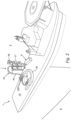
- the first length 4a that is hanging over the overboarding guide means 33 and downwards into the water mass 5 is caught by the hang-off clamp 39.
- the clamp part 39a clamps a cable length 4a, and holds it in position since the clamp part 39a is suspended from the rope 39b (or more ropes 39b) that connects to the vessel, for instance near the overboarding guide means 33.
- This allows the first cable length 4a to be held while making that part of the first cable length 4a that extends between the clamp part 39a and its free end 4a-1 to be substantially stress-free. In this situation, advancing the first cable length 4a is halted when the end 4a-1 of the first cable length 4a is encountered.
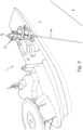
- the first cable length 4a is then advanced over the support surface 33a of the overboarding guide means 33 until the free end 4a-1 is located downstream of the overboarding guide means 33 at the height of the downstream guiding means 61.
- the support surface 33a of the semi-circular plate 33c is free from cable.
- the free end 4a-1 of the first cable length 4a is then provided over the downstream guiding means 61 and into the entrance 6a of the cable joining unit 6, by hauling the rope 39b.
- a second length 4b of cable 4 is then reeled off from the second storage unit 32b, through a second deck penetration 11b and led over part of the conveying structure 38 to the entrance 6b of the cable joining unit 6.
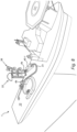
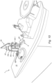
- the two ends of the cable lengths (4a, 4b) are then joined in the joining unit 6 according to well known practice, which may involve providing the joint direction 40 with a rigid protective cover or sleeve 40-1 ( figure 7 ), and which may optionally involve providing parts of the cable ends (4a, 4b) at both sides of the joint 40 with bend restrictors 41 ( figure 8 ), in order to safeguard the cable shape when it is taken up by the hoisting crane 36 ( figure 9 ).
- part of the second cable end 4b is taken up by the hoisting crane 36, which is for this purpose, optionally provided with a hoisting frame 42.
- the roof 60 thereof may be slid away, or tilted into an open position, as shown.
- the joining unit may be removed in part or as a whole.
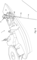
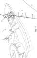
- the hoisting crane 36 lifts the second cable end 4b, optionally protected by the bend restrictor 41, until is takes support on the support surface 33a of the semi-circular plate 33c of the overboarding guide means 33, as shown in figure 10 . In this position, the joint 40 and protective sleeve 40-1 are provided downstream of the overboarding guide means 33.
- the second length 4b of the cable 4 is then overboarded in the direction 43 towards the water mass 5 with the first cable length 4a joined thereto, while being supported by the support surface 33a of the overboarding guide means 33, and by the hang off clamp 39, until an end of the second length 4b of the cable 4 may be encountered.
- the second length 4b of the cable is advanced by the tensioners 31. Support of the joined cables length (4a, 4b) by the hang off clamp 39 reliefs stresses in the joined cable lengths (4a, 4b) and the joint.
- the method according to the invention allows overboarding the elongated flexible cable 4 from the vessel 1, wherein the cable 4 comprises a joint 40 between a first length 4a and a second length 4b thereof, with less risk for damage to the joint 40 or the flexible cable 4 itself.
- the increased total length of the jointed cable (4a, 4b) may be used to supply the distance needed for routes through high depths.
Landscapes
- Engineering & Computer Science (AREA)
- General Engineering & Computer Science (AREA)
- Mechanical Engineering (AREA)
- Chemical & Material Sciences (AREA)
- Combustion & Propulsion (AREA)
- Ocean & Marine Engineering (AREA)
- Electric Cable Installation (AREA)
- Laying Of Electric Cables Or Lines Outside (AREA)
- Massaging Devices (AREA)
Claims (16)
- Verfahren zum Überborden eines länglichen, flexiblen Artikels (4) aus einem Schiff (1), der eine Verbindung (40) zwischen einer ersten und einer nachfolgenden zweiten Länge desselben aufweist, wobei das Verfahren die folgenden Schritte umfasst:a) Vorschieben einer ersten Länge (4a) des Artikels (4) von einer Lagereinheit (32a, 32b) zu einem Überbordführungsmittel (33), das in einer Höhe über einem Arbeitsdeck (10) des Schiffs (1) vorgesehen ist, und Überborden der von dem Überbordführungsmittel (33) gestützten ersten Artikellänge (4a), bis ein Ende der ersten Länge (4a) des Artikels (4) erreicht ist;b) Halten der überstehenden ersten Artikellänge (4a) mit einem Haltemittel, das zum Tragen der überstehenden ersten Artikellänge (4a) konfiguriert ist;c) Führen eines Endes der ersten Artikellänge (4a), die von den Haltemitteln gehalten wird, zu einer Verbindungseinheit (6) zum Herstellen einer Verbindung (40), die auf dem Arbeitsdeck (10) des Schiffes (1) angeordnet ist;d) Vorschieben einer zweiten Länge (4b) des Artikels (4) zu der Verbindungseinheit (6) auf dem Arbeitsdeck (10) des Schiffs (1) und Verbinden der Enden der ersten und zweiten Artikellänge, um die Verbindung (40) auf dem Arbeitsdeck (10) des Schiffs (1) zu erhalten;e) während die erste Artikellänge (4a) noch gehalten wird, Aufnehmen der so vorbereiteten Verbindung (40) aus der Verbindungseinheit (6) und Bringen derselben zu dem Überbordführungsmittel (33), so dass ein Teil der zweiten Artikellänge (4b) durch die Überbordführungsmittel (33) gestützt wird und sich die Verbindung (40) in einer stromabwärtigen Position in Bezug auf die Überbordführungsmittel (33) befindet; undf) Überborden der zweiten Artikellänge (4b) mit der damit verbundenen ersten Artikellänge (4a), die von dem Überbordführungsmittel (33) und wahlweise von dem Haltemittel gestützt wird, bis ein Ende der zweiten Länge (4b) des Artikels (4) erreicht ist.
- Verfahren nach Anspruch 1, wobei das Vorschieben der ersten Artikellänge (4a) angehalten wird, wenn das Ende der ersten Länge (4a) des Artikels (4) erreicht ist.
- Verfahren nach Anspruch 1 oder 2, wobei das Halten der ersten Länge (4a) des Artikels (4) das Aufhängen der ersten Länge (4a) in einer Abhängeklemme (39) umfasst, wenn das Ende der ersten Länge (4a) des Artikels (4) erreicht wird, um den Teil der ersten Artikellänge (4a), der sich zwischen dem Ende und der Abhängeklemme (39) erstreckt, im Wesentlichen zu entlasten.
- Verfahren nach einem der vorhergehenden Ansprüche, wobei die verbundenen Enden der ersten und zweiten Längen (4a, 4b) des Artikels (4) durch eine Schutzhülle (40-1) geschützt werden.
- Verfahren nach einem der vorhergehenden Ansprüche, wobei die erste und die zweite Länge (4a, 4b) des Artikels (4) über eine Distanz auf beiden Seiten der Verbindung (40) durch Biegebegrenzer (41) geschützt werden.
- Verfahren nach Anspruch 5, wobei die Distanzen, über die sich die Biegebegrenzer (41) beiderseits der Verbindung (40) erstrecken, zusammen mindestens eine Länge der den Gegenstand (4) tragenden Überbordführungsmittel (33) abdecken.
- Verfahren nach einem der vorhergehenden Ansprüche, wobei der Artikel (4) über eine gekrümmte Auflage geführt wird, die eine kontinuierliche und/oder diskontinuierliche Auflagefläche der Überbordführungsmittel (33), vorzugsweise eine halbkreisförmige Auflagefläche (33a), bereitstellt.
- Verfahren nach einem der vorhergehenden Ansprüche, wobei die vorbereitete Verbindung (40) mittels eines Hebekrans (36) von der Verbindungseinheit (6) abgehoben wird.
- Verfahren nach einem der vorhergehenden Ansprüche, wobei das Vorschieben der ersten und zweiten Länge (4a, 4b) des Artikels durch Spanner (31) erfolgt, die gegebenenfalls an der Überbordführungseinrichtung (33) vorgesehen sind.
- Vorrichtung (3) zum Überborden eines länglichen flexiblen Artikels (4) von einem Schiff (1), der eine Verbindung (40) zwischen einem ersten und einem zweiten Abschnitt (4a, 4b) desselben aufweist, wobei die Vorrichtung (3) eine Speichereinheit (32a, 32b) für jeden der ersten und nachfolgenden zweiten Artikelabschnitte (4a, 4b) umfasst, und Artikelträgermittel (38) zum Vorwärtsbewegen der Artikellängen (4a, 4b) von der Speichereinheit (32a, 32b) zu Überbordführungsmitteln (33), die in einer Höhe über einem Arbeitsdeck (10) des Schiffes (1) vorgesehen und so konfiguriert sind, dass sie eine Artikellänge (4a) tragen und die Artikellänge (4a) überborden, wobei die Vorrichtung (3) ferner ein Haltemittel umfasst, das so konfiguriert ist, dass es eine über Bord gegangene erste Artikellänge (4a) hält und trägt, eine Verbindungseinheit (6), die auf dem Arbeitsdeck (10) des Schiffes (1) positioniert und so konfiguriert ist, dass sie Enden der ersten und zweiten Artikellänge (4a, 4b) verbindet, um die Verbindung (40) auf dem Arbeitsdeck (10) des Schiffes (1) zu erhalten, und Handhabungsmittel, die so konfiguriert sind, dass sie eine vorbereitete Verbindung (40) von der Verbindungseinheit (6) aufnimmt und sie zu dem Überbordführungsmittel (33) bringt, so dass ein Teil der zweiten Artikellänge (4b) von dem Überbordführungsmittel (33) und der Halteeinrichtung gestützt wird und sich die Verbindung (40) in einer stromabwärtigen Position in Bezug auf die Überbordführungseinrichtung (33) befindet.
- Vorrichtung (3) nach Anspruch 10, wobei die Haltemittel eine Abhängeklammer (39) umfassen, die so konfiguriert ist, dass sie eine überbordende Länge des Artikels (4) aufhängt.
- Vorrichtung (3) nach Anspruch 10 oder 11, wobei die Verbindungseinheit (6) in Bezug auf die vorrückende Artikellänge (4a, 4b) an einem stromabwärtigen Ende des Überbordführungsmittels (33) positioniert ist.
- Vorrichtung (3) nach einem der Ansprüche 10 bis 12, wobei das Überbordführungsmittel (33) eine gekrümmte, entweder durchgehende oder unterbrochene Stützfläche umfasst, das zur Führung des Artikels (4) ausgebildet ist, vorzugsweise eine halbkreisförmige Stützfläche (33a).
- Vorrichtung (3) nach einem der Ansprüche 10 bis 13, wobei die Handhabungsmittel einen Hebekran (36) umfassen.
- Vorrichtung (3) nach einem der Ansprüche 10 bis 14, wobei die Artikelstützmittel (38) Spanner (31) umfassen, die optional an dem darüber liegenden Führungsmittel (33) vorgesehen sind.
- Schiff (1) umfassend eine Vorrichtung (3) nach einem der Ansprüche 10 bis 15 zum Überborden eines länglichen, flexiblen Artikels (4), der zwischen einer ersten und einer zweiten Länge (4a, 4b) davon eine Verbindung (40) umfasst.
Applications Claiming Priority (1)
| Application Number | Priority Date | Filing Date | Title |
|---|---|---|---|
| NL2027624A NL2027624B1 (en) | 2021-02-23 | 2021-02-23 | Method and device for overboarding from a vessel a jointed elongated flexible article |
Publications (2)
| Publication Number | Publication Date |
|---|---|
| EP4046903A1 EP4046903A1 (de) | 2022-08-24 |
| EP4046903B1 true EP4046903B1 (de) | 2025-04-02 |
Family
ID=76159892
Family Applications (1)
| Application Number | Title | Priority Date | Filing Date |
|---|---|---|---|
| EP22155523.8A Active EP4046903B1 (de) | 2021-02-23 | 2022-02-08 | Verfahren und vorrichtung zum überborden eines verbundenen länglichen flexiblen artikels aus einem schiff |
Country Status (2)
| Country | Link |
|---|---|
| EP (1) | EP4046903B1 (de) |
| NL (1) | NL2027624B1 (de) |
Families Citing this family (1)
| Publication number | Priority date | Publication date | Assignee | Title |
|---|---|---|---|---|
| GB2644200A (en) * | 2024-09-19 | 2026-03-25 | Subsea 7 Ltd | Incorporating structures into reeled pipelines |
Family Cites Families (5)
| Publication number | Priority date | Publication date | Assignee | Title |
|---|---|---|---|---|
| BR9904117A (pt) * | 1999-09-08 | 2001-04-24 | Petroleo Brasileiro Sa | Método para instalação de uma tubulação metálica submarina ascendente em catenária |
| GB0715545D0 (en) * | 2007-08-10 | 2007-09-19 | Acergy Uk Ltd | Pipeline laying apparatus and method |
| BE1021791B1 (nl) * | 2013-10-18 | 2016-01-18 | Jan De Nul, Naamloze Vennootschap | Een inrichting voor het opwikkelen en afwikkelen van een kabel en werkwijze om een kabel op te wikkelen |
| GB2547418A (en) * | 2016-02-12 | 2017-08-23 | Philp Barry | Friction grip lay system |
| WO2020180178A1 (en) * | 2019-03-01 | 2020-09-10 | Itrec B.V. | Vessel and method for offshore cable laying |
-
2021
- 2021-02-23 NL NL2027624A patent/NL2027624B1/en active
-
2022
- 2022-02-08 EP EP22155523.8A patent/EP4046903B1/de active Active
Also Published As
| Publication number | Publication date |
|---|---|
| NL2027624A (en) | 2022-09-20 |
| EP4046903A1 (de) | 2022-08-24 |
| NL2027624B1 (en) | 2022-09-20 |
Similar Documents
| Publication | Publication Date | Title |
|---|---|---|
| EP3558810B1 (de) | Vorrichtung und verfahren zur ausgabe eines länglichen flexiblen artikels aus einem behälter | |
| EP2331860B1 (de) | Verfahren und vorrichtung zur aufgabe und rückgewinnung eines meeresrohres | |
| EP1850043B1 (de) | System und Verfahren zur Außerbetriebsetzung und Wiederherstellung sowie Kabelverbinder | |
| CN102438886A (zh) | 操纵缆绳的方法和设备 | |
| EP3137801B1 (de) | Meerespipelineinstallationsleger mit spulenverfahren und verfahren | |
| US20130084135A1 (en) | Apparatus and method of laying pipeline | |
| US6149347A (en) | Methods of laying seabed pipelines | |
| WO2004085898A1 (en) | Apparatus and methods for laying of elongate articles from a vessel | |
| EP4046903B1 (de) | Verfahren und vorrichtung zum überborden eines verbundenen länglichen flexiblen artikels aus einem schiff | |
| CN107250639B (zh) | 海上管道安装系统和海上管道安装方法 | |
| US20170346264A1 (en) | Method And Apparatus For Performing Cable Lay And Connection Operations | |
| EP3931075B1 (de) | Schiff und verfahren zur verlegung von offshore-kabeln | |
| CN112204287B (zh) | 海洋管道铺设船及通过j型管道铺设方法进行管道铺设的方法 | |
| WO2017109579A1 (en) | Direct tie-in method | |
| CN107750316B (zh) | 用于两侧电缆布设的灵活电缆输送系统 | |
| EP4490035B1 (de) | Meerwassereinlasssteigrohr | |
| EP4388234B1 (de) | Verfahren zum verlegen einer anordnung aus einem flexiblen länglichen element und einem starren zubehör zum eintauchen in wasser von einem installationsschiff, baugruppe für dessen unterwasserinstallation | |
| WO2010107319A1 (en) | Assembly for pipelaying | |
| JP2025001735A (ja) | ケーブル布設構造の製造方法、ケーブル接続中間体、およびケーブル布設構造 | |
| US20130230356A1 (en) | Line-laying operations | |
| WO2025120109A1 (en) | Vessel and method for handling a power cable |
Legal Events
| Date | Code | Title | Description |
|---|---|---|---|
| PUAI | Public reference made under article 153(3) epc to a published international application that has entered the european phase |
Free format text: ORIGINAL CODE: 0009012 |
|
| STAA | Information on the status of an ep patent application or granted ep patent |
Free format text: STATUS: THE APPLICATION HAS BEEN PUBLISHED |
|
| AK | Designated contracting states |
Kind code of ref document: A1 Designated state(s): AL AT BE BG CH CY CZ DE DK EE ES FI FR GB GR HR HU IE IS IT LI LT LU LV MC MK MT NL NO PL PT RO RS SE SI SK SM TR |
|
| STAA | Information on the status of an ep patent application or granted ep patent |
Free format text: STATUS: REQUEST FOR EXAMINATION WAS MADE |
|
| 17P | Request for examination filed |
Effective date: 20230216 |
|
| RBV | Designated contracting states (corrected) |
Designated state(s): AL AT BE BG CH CY CZ DE DK EE ES FI FR GB GR HR HU IE IS IT LI LT LU LV MC MK MT NL NO PL PT RO RS SE SI SK SM TR |
|
| REG | Reference to a national code |
Ref country code: DE Free format text: PREVIOUS MAIN CLASS: B63B0035040000 Ipc: B63B0035030000 Ref country code: DE Ref legal event code: R079 Ref document number: 602022012418 Country of ref document: DE Free format text: PREVIOUS MAIN CLASS: B63B0035040000 Ipc: B63B0035030000 |
|
| GRAP | Despatch of communication of intention to grant a patent |
Free format text: ORIGINAL CODE: EPIDOSNIGR1 |
|
| STAA | Information on the status of an ep patent application or granted ep patent |
Free format text: STATUS: GRANT OF PATENT IS INTENDED |
|
| RIC1 | Information provided on ipc code assigned before grant |
Ipc: F16L 1/20 20060101ALI20240918BHEP Ipc: F16L 1/19 20060101ALI20240918BHEP Ipc: B63B 35/04 20060101ALI20240918BHEP Ipc: B63B 35/03 20060101AFI20240918BHEP |
|
| INTG | Intention to grant announced |
Effective date: 20241021 |
|
| GRAS | Grant fee paid |
Free format text: ORIGINAL CODE: EPIDOSNIGR3 |
|
| GRAA | (expected) grant |
Free format text: ORIGINAL CODE: 0009210 |
|
| STAA | Information on the status of an ep patent application or granted ep patent |
Free format text: STATUS: THE PATENT HAS BEEN GRANTED |
|
| AK | Designated contracting states |
Kind code of ref document: B1 Designated state(s): AL AT BE BG CH CY CZ DE DK EE ES FI FR GB GR HR HU IE IS IT LI LT LU LV MC MK MT NL NO PL PT RO RS SE SI SK SM TR |
|
| REG | Reference to a national code |
Ref country code: GB Ref legal event code: FG4D |
|
| REG | Reference to a national code |
Ref country code: CH Ref legal event code: EP |
|
| REG | Reference to a national code |
Ref country code: IE Ref legal event code: FG4D |
|
| REG | Reference to a national code |
Ref country code: DE Ref legal event code: R096 Ref document number: 602022012418 Country of ref document: DE |
|
| P01 | Opt-out of the competence of the unified patent court (upc) registered |
Free format text: CASE NUMBER: APP_15612/2025 Effective date: 20250331 |
|
| REG | Reference to a national code |
Ref country code: NL Ref legal event code: MP Effective date: 20250402 |
|
| REG | Reference to a national code |
Ref country code: GR Ref legal event code: EP Ref document number: 20250401329 Country of ref document: GR Effective date: 20250808 |
|
| PG25 | Lapsed in a contracting state [announced via postgrant information from national office to epo] |
Ref country code: NL Free format text: LAPSE BECAUSE OF FAILURE TO SUBMIT A TRANSLATION OF THE DESCRIPTION OR TO PAY THE FEE WITHIN THE PRESCRIBED TIME-LIMIT Effective date: 20250402 |
|
| REG | Reference to a national code |
Ref country code: AT Ref legal event code: MK05 Ref document number: 1781076 Country of ref document: AT Kind code of ref document: T Effective date: 20250402 |
|
| PG25 | Lapsed in a contracting state [announced via postgrant information from national office to epo] |
Ref country code: FI Free format text: LAPSE BECAUSE OF FAILURE TO SUBMIT A TRANSLATION OF THE DESCRIPTION OR TO PAY THE FEE WITHIN THE PRESCRIBED TIME-LIMIT Effective date: 20250402 Ref country code: PT Free format text: LAPSE BECAUSE OF FAILURE TO SUBMIT A TRANSLATION OF THE DESCRIPTION OR TO PAY THE FEE WITHIN THE PRESCRIBED TIME-LIMIT Effective date: 20250804 Ref country code: ES Free format text: LAPSE BECAUSE OF FAILURE TO SUBMIT A TRANSLATION OF THE DESCRIPTION OR TO PAY THE FEE WITHIN THE PRESCRIBED TIME-LIMIT Effective date: 20250402 |
|
| REG | Reference to a national code |
Ref country code: LT Ref legal event code: MG9D |
|
| PG25 | Lapsed in a contracting state [announced via postgrant information from national office to epo] |
Ref country code: NO Free format text: LAPSE BECAUSE OF FAILURE TO SUBMIT A TRANSLATION OF THE DESCRIPTION OR TO PAY THE FEE WITHIN THE PRESCRIBED TIME-LIMIT Effective date: 20250702 |
|
| PG25 | Lapsed in a contracting state [announced via postgrant information from national office to epo] |
Ref country code: PL Free format text: LAPSE BECAUSE OF FAILURE TO SUBMIT A TRANSLATION OF THE DESCRIPTION OR TO PAY THE FEE WITHIN THE PRESCRIBED TIME-LIMIT Effective date: 20250402 |
|
| PG25 | Lapsed in a contracting state [announced via postgrant information from national office to epo] |
Ref country code: BG Free format text: LAPSE BECAUSE OF FAILURE TO SUBMIT A TRANSLATION OF THE DESCRIPTION OR TO PAY THE FEE WITHIN THE PRESCRIBED TIME-LIMIT Effective date: 20250402 |
|
| PG25 | Lapsed in a contracting state [announced via postgrant information from national office to epo] |
Ref country code: HR Free format text: LAPSE BECAUSE OF FAILURE TO SUBMIT A TRANSLATION OF THE DESCRIPTION OR TO PAY THE FEE WITHIN THE PRESCRIBED TIME-LIMIT Effective date: 20250402 |
|
| PG25 | Lapsed in a contracting state [announced via postgrant information from national office to epo] |
Ref country code: AT Free format text: LAPSE BECAUSE OF FAILURE TO SUBMIT A TRANSLATION OF THE DESCRIPTION OR TO PAY THE FEE WITHIN THE PRESCRIBED TIME-LIMIT Effective date: 20250402 |
|
| PG25 | Lapsed in a contracting state [announced via postgrant information from national office to epo] |
Ref country code: RS Free format text: LAPSE BECAUSE OF FAILURE TO SUBMIT A TRANSLATION OF THE DESCRIPTION OR TO PAY THE FEE WITHIN THE PRESCRIBED TIME-LIMIT Effective date: 20250702 |
|
| PG25 | Lapsed in a contracting state [announced via postgrant information from national office to epo] |
Ref country code: IS Free format text: LAPSE BECAUSE OF FAILURE TO SUBMIT A TRANSLATION OF THE DESCRIPTION OR TO PAY THE FEE WITHIN THE PRESCRIBED TIME-LIMIT Effective date: 20250802 |
|
| PG25 | Lapsed in a contracting state [announced via postgrant information from national office to epo] |
Ref country code: LV Free format text: LAPSE BECAUSE OF FAILURE TO SUBMIT A TRANSLATION OF THE DESCRIPTION OR TO PAY THE FEE WITHIN THE PRESCRIBED TIME-LIMIT Effective date: 20250402 |
|
| REG | Reference to a national code |
Ref country code: DE Ref legal event code: R097 Ref document number: 602022012418 Country of ref document: DE |
|
| PG25 | Lapsed in a contracting state [announced via postgrant information from national office to epo] |
Ref country code: DK Free format text: LAPSE BECAUSE OF FAILURE TO SUBMIT A TRANSLATION OF THE DESCRIPTION OR TO PAY THE FEE WITHIN THE PRESCRIBED TIME-LIMIT Effective date: 20250402 Ref country code: SM Free format text: LAPSE BECAUSE OF FAILURE TO SUBMIT A TRANSLATION OF THE DESCRIPTION OR TO PAY THE FEE WITHIN THE PRESCRIBED TIME-LIMIT Effective date: 20250402 |
|
| PG25 | Lapsed in a contracting state [announced via postgrant information from national office to epo] |
Ref country code: CZ Free format text: LAPSE BECAUSE OF FAILURE TO SUBMIT A TRANSLATION OF THE DESCRIPTION OR TO PAY THE FEE WITHIN THE PRESCRIBED TIME-LIMIT Effective date: 20250402 |
|
| PG25 | Lapsed in a contracting state [announced via postgrant information from national office to epo] |
Ref country code: EE Free format text: LAPSE BECAUSE OF FAILURE TO SUBMIT A TRANSLATION OF THE DESCRIPTION OR TO PAY THE FEE WITHIN THE PRESCRIBED TIME-LIMIT Effective date: 20250402 |
|
| PG25 | Lapsed in a contracting state [announced via postgrant information from national office to epo] |
Ref country code: SK Free format text: LAPSE BECAUSE OF FAILURE TO SUBMIT A TRANSLATION OF THE DESCRIPTION OR TO PAY THE FEE WITHIN THE PRESCRIBED TIME-LIMIT Effective date: 20250402 |
|
| PLBE | No opposition filed within time limit |
Free format text: ORIGINAL CODE: 0009261 |
|
| STAA | Information on the status of an ep patent application or granted ep patent |
Free format text: STATUS: NO OPPOSITION FILED WITHIN TIME LIMIT |
|
| REG | Reference to a national code |
Ref country code: CH Ref legal event code: L10 Free format text: ST27 STATUS EVENT CODE: U-0-0-L10-L00 (AS PROVIDED BY THE NATIONAL OFFICE) Effective date: 20260211 |
|
| 26N | No opposition filed |
Effective date: 20260105 |
|
| PGFP | Annual fee paid to national office [announced via postgrant information from national office to epo] |
Ref country code: IT Payment date: 20260130 Year of fee payment: 5 |
|
| PGFP | Annual fee paid to national office [announced via postgrant information from national office to epo] |
Ref country code: GR Payment date: 20260206 Year of fee payment: 5 Ref country code: CY Payment date: 20260121 Year of fee payment: 5 |