EP4046891A1 - Motorised handling device for pushing and/or towing at least one carriage and handling assembly comprising such a device - Google Patents
Motorised handling device for pushing and/or towing at least one carriage and handling assembly comprising such a device Download PDFInfo
- Publication number
- EP4046891A1 EP4046891A1 EP21315023.8A EP21315023A EP4046891A1 EP 4046891 A1 EP4046891 A1 EP 4046891A1 EP 21315023 A EP21315023 A EP 21315023A EP 4046891 A1 EP4046891 A1 EP 4046891A1
- Authority
- EP
- European Patent Office
- Prior art keywords
- coupling element
- longitudinal axis
- motorized
- vehicle
- carriage
- Prior art date
- Legal status (The legal status is an assumption and is not a legal conclusion. Google has not performed a legal analysis and makes no representation as to the accuracy of the status listed.)
- Withdrawn
Links
Images


Classifications
-
- B—PERFORMING OPERATIONS; TRANSPORTING
- B62—LAND VEHICLES FOR TRAVELLING OTHERWISE THAN ON RAILS
- B62B—HAND-PROPELLED VEHICLES, e.g. HAND CARTS OR PERAMBULATORS; SLEDGES
- B62B3/00—Hand carts having more than one axis carrying transport wheels; Steering devices therefor; Equipment therefor
- B62B3/04—Hand carts having more than one axis carrying transport wheels; Steering devices therefor; Equipment therefor involving means for grappling or securing in place objects to be carried; Loading or unloading equipment
-
- B—PERFORMING OPERATIONS; TRANSPORTING
- B62—LAND VEHICLES FOR TRAVELLING OTHERWISE THAN ON RAILS
- B62B—HAND-PROPELLED VEHICLES, e.g. HAND CARTS OR PERAMBULATORS; SLEDGES
- B62B5/00—Accessories or details specially adapted for hand carts
- B62B5/0026—Propulsion aids
-
- B—PERFORMING OPERATIONS; TRANSPORTING
- B62—LAND VEHICLES FOR TRAVELLING OTHERWISE THAN ON RAILS
- B62B—HAND-PROPELLED VEHICLES, e.g. HAND CARTS OR PERAMBULATORS; SLEDGES
- B62B5/00—Accessories or details specially adapted for hand carts
- B62B5/0026—Propulsion aids
- B62B5/0033—Electric motors
-
- B—PERFORMING OPERATIONS; TRANSPORTING
- B62—LAND VEHICLES FOR TRAVELLING OTHERWISE THAN ON RAILS
- B62B—HAND-PROPELLED VEHICLES, e.g. HAND CARTS OR PERAMBULATORS; SLEDGES
- B62B5/00—Accessories or details specially adapted for hand carts
- B62B5/0026—Propulsion aids
- B62B5/0079—Towing by connecting to another vehicle
Definitions
- the present invention relates to the field of handling and relates to a motorized handling device for pushing and/or towing at least one trolley. It also relates to a handling assembly comprising such a device.
- trolleys In the field of handling and transport, trolleys are already known, generally equipped with fixed wheels and/or swivel wheels, making it possible to transport heavy or less heavy loads of different sizes on all types of floors in complete safety.
- trolleys with or without drop sides, removable or fixed or even trolleys with a tray or shelves above said tray.
- carriages are pushed or towed manually by a user from one point to another and certain carriages benefit from motorization making it possible to assist the pushing or pulling by the user.
- motor-assisted trucks some are self-propelled, i.e. they have their own motorization and motorization control, and others are adapted to be coupled to a pusher/tractor equipped with motorization and its control.
- the pusher/tractor is generally designed to push or tow a single carriage coupled to the latter or a train of carriages, the first carriage of which is coupled to said pusher/tractor.
- Such cart(s) pusher/tractor is disclosed by document US2018/0304912 .
- the motorized pushing device comprises a base in the form of a tray mounted on four swivel castors, two front castors and two rear castors, a motor located under said base and coupled to said front wheels, a right control handle and a left control handle, a guide handle and a battery supplying the motor.
- the trolley has a base in the form of a tray mounted on four external pivoting wheels and two central guide wheels capable of being lowered to be in contact with the ground or raised.
- the base of the motorized pushing device is located at a height above the ground, i.e.
- the carriage further comprises at the rear of the base a coupling bar allowing its coupling with the motorized pushing device using latches or bolts mounted at the rear of the base of said device.
- a motorized pushing device of the type disclosed by the document US2018/0304912 does not have sufficient technical qualities to give it, in particular, good maneuverability and/or sufficient safety of use.
- the object of the present invention is to overcome these drawbacks by proposing a motorized handling device for pushing and/or towing at least one transport carriage, which is more maneuverable than the current devices, while improving the safety of the user.
- the motorized handling device for pushing and/or towing at least one trolley, said device comprising a motorized pushing and/or tractor vehicle extending along a longitudinal axis, called the first longitudinal axis, and being adapted and intended to be coupled to a trolley provided with castors for pushing or towing the latter, said vehicle comprising a base mounted on castors and on a motorized wheel unit, at least one guide handle, means command and/or control allowing the command and/or the control of the motorized wheel unit and a power supply of the battery type, said base of the vehicle being adapted and intended to come, at least in part, to be positioned under the base of a carriage extending along a longitudinal axis, said second longitudinal axis, to achieve their coupling, is essentially characterized in that it further comprises at least a first coupling element fe melle, respectively male, extending along a longitudinal axis, called the third longitudinal axis, and being suitable and intended to be fixed under the base of a trolley
- the present invention also relates to a handling assembly comprising a motorized handling device and at least one carriage, characterized in that said motorized handling device consists of a motorized handling device according to the present invention and in that the or each first female coupling element, respectively male, is fixed under the base of the or one of the carriage(s) being centered on the longitudinal axis of the said carriage.
- the appended figures show a motorized handling device, according to the present invention, for pushing and/or towing at least one trolley, said device comprising a motorized pusher and/or tractor vehicle 1 extending along a longitudinal axis, called first longitudinal axis X1, and being able and intended to be coupled to a carriage 2 provided with (or mounted on) wheels 2a to push or tow the latter.
- the vehicle 1 comprises a base 1a mounted on rollers 1b and on a motorized wheel unit 1c, at least one guide handle 1d, command and/or control means 1h, 1i, 1j, 1k allowing the command and/or or controlling the motorized wheel unit 1c and a battery type power supply 1e.
- the base 1a of the vehicle 1 is able and intended to come, at least in part, to be positioned under the base 2a of a carriage 2 extending along a longitudinal axis, said second longitudinal axis X2, to achieve their coupling , that is to say the coupling of said carriage 2 and said vehicle 1.
- such a device further comprises at least one first coupling element 3 female, respectively male, extending along a longitudinal axis, called third longitudinal axis X3, and being able and intended to be fixed under the base 2b of a carriage 2 being centered on the second longitudinal axis X2 and a second male, respectively female coupling element 10a, forming a part of the base 1a of the vehicle 1 located at the front and centered on the first longitudinal axis X1, said first and second coupling elements 3, 10a being of complementary shape and capable of cooperating with each other by mutual interlocking to be placed in a nested state allowing the vehicle 1 to be coupled with a trolley 2 equipped with such a coupling element coupling by interlocking 3 and, possibly, locking means 4 of the coupling.
- the wheels 1b of the vehicle are pivoting.
- the rollers 2a of the carriage 2 are preferably pivoting.
- carriage 2 equipped with a coupling element by interlocking 3 can be for example a carriage 2 with sides 2c, fixed or removable. It can also be seen that such a carriage 2 can be provided to include one or more shelves 2d.
- Other types of carriages 2, not shown in the appended figures, can be provided to be equipped with a coupling element by interlocking 3 according to the present invention such as carriages 2 without sides, that is to say only with a plate forming at least part of the base 2b.
- the second male coupling element 10a where applicable the first male coupling element 3, comprises a nesting end 100a.
- the first female coupling element 3, where appropriate the second female coupling element 10a comprises two longitudinally opposite ends 3a, 3b, namely an open end 3a adapted to receive said end 100a for fitting the second male coupling element 10a, if applicable of the first coupling element male 3, in order to achieve mutual interlocking and a bottom end 3b internally defining the bottom of the interlocking.
- the second male coupling element 10a where appropriate the first male coupling element 3, comprises an end part 101a comprising the nesting end 100a and tapering to to the latter or being flared towards the rear from the latter (see in particular the figure 2 , 4 , 5 , 6 and 7 ).
- the end part 101a is in the shape of a flared U and the interlocking end 100a forms the base of said U.
- the second male coupling element 10a where appropriate the first male coupling element 3 has a central guide part extending said end part 101a behind the latter and being delimited laterally by two guide sides 102a lateral located on either side of the first longitudinal axis X1, if necessary of the third longitudinal axis X3.
- said lateral guide sides 102a extend parallel to said first longitudinal axis X1, where applicable to said third longitudinal axis X3.
- Motorized unit 1c includes at least one wheel 10c.
- the present invention can provide, preferably, that the or each wheel 10c can be moved into a lowered position in contact with the ground or the surface on which the vehicle 1 is moving and into a raised position where the or each wheel 10c is not is more in frictional contact with said ground or said surface.
- the first female coupling element 3 where applicable the second female coupling element 10a, comprises a centering and/or latching finger 3c, preferably of generally cylindrical or conical shape, fixed to the bottom of the interlocking and centered on the third longitudinal axis X3, if necessary on the first longitudinal axis X1, extending axially towards the open end 3a.
- the nesting end 100a of the second male coupling element 10a if applicable of the first male coupling element 3, comprises a centering and/or hooking hole 103a, centered on the first longitudinal axis X1, if necessary on the third longitudinal axis X3.
- the centering and/or attachment hole 103a is suitable and intended to receive said centering and/or attachment pin 3c at least in the coupling state ( figure 2 , 6 and 7 ).
- the first female coupling element 3, where appropriate the second female coupling element 10a comprises a centering and/or hooking hole made in the interlocking bottom and centered on the third longitudinal axis X3, where applicable on the first longitudinal axis X1, and in that the interlocking end 100a of the second male coupling element 10a, where applicable the fitting end of the first male coupling element 3, is extended externally and axially by a centering and/or hooking finger, centered on the first longitudinal axis X1, where appropriate on the third longitudinal axis X3, said hole centering and / or attachment being adapted to receive said centering pin and / or attachment in the coupling state.
- the second male coupling element 10a if necessary the first male coupling element 3, has a lower face 104a and carries the motorized wheel unit 1c which is mounted on said lower face 104a.
- the vehicle 1 comprises at the rear an upright 1f comprising a lower end fixed to the base 1a and an upper end comprising an arm 1g of the steering handlebar type carrying the steering handle(s). 1d guide, preferably two guide handles.
- the upright 1f can support the battery-type power supply 1e.
- such an upright 1f is in a central position at the rear of the vehicle 1, that is to say extending vertically in the longitudinal median plane of said vehicle 1.
- control and/or control means 1h, 1i, 1d, 1k can comprise, for example, a control box 1h and a control button 1i.
- the control box 1h is operatively connected to the motorized wheel unit 1c and to said control button 1i and can be mounted on the upright 1f.
- the control box 1h can comprise a box containing an electronic card comprising the command and control parameters such as the speed and the motor torque of the motorized wheel unit 1c.
- the control button 1i makes it possible, for example, to control the speed, preferably gradually and/or the forward or reverse gear.
- the speed can be set in the control box 1h so as not to exceed a programmed maximum speed when the control button 1i is actuated.
- control button 1i can be mounted in the or one of the guide handle(s) 1d, for example at the end of the latter, for example in a manner similar to an accelerator button of a handle of throttle lever for moped or motorcycle.
- the command and control means 1h, 1i, 1d, 1k can also comprise a display screen 1d making it possible to display, for example, the speed, the forward or reverse gear or any other parameter relating to the command and control of the motorized wheel unit 1c and of the vehicle 1.
- the command and control means 1h, 1i, 1j, 1k can also comprise a removable storage medium 1k, such as a USB key , making it possible to modify and/or program the control/piloting parameters such as the speed and/or the torque, in particular the torque at start-up and/or while driving.
- a storage medium 1k can be inserted into the control box 1h.
- Such a 1k storage medium can also be a portable storage medium 1k of the tablet or smartphone type or a computer capable of communicating, for example by electric wire or radio waves, with the control box 1h to exchange with the latter, configured for this purpose, information and/ or files containing in particular the aforementioned adjustment parameters.
- the second male coupling element 10a if necessary the first male coupling element 3, generally has the shape of a rectangular, hexagonal or octagonal prism, or a part of said shape.
- the first female coupling element 3, where appropriate the second female coupling element 10a may have a similar shape, that is to say a rectangular, hexagonal or octagonal prism, or a part of said form.
- first coupling element 3 and the second coupling element 10a in their male or female form, can be made from an assembly of flat bars.
- the first coupling element 3 and the second coupling element 10a have a frame shape.
- a frame can preferably have one of the aforementioned prismatic shapes.
- Such a frame is open on at least one of its sides to form the open end 3a (see figure 4 notably).
- the vehicle 1 can also comprise at least two centering lugs 1g flared forwards and arranged on each side of the base 1a of said vehicle 1, preferably towards the rear of said vehicle 1 (see in particular the figure 1 , 2 , 4 , 5 , 6 and 7 ). These 1g centering lugs make it easier to guide during insertion for interlocking ( figure 1 , 2 , 5 , 6 and 7 ).
- the locking means 4 comprise at least one locking latch 4a mounted on or in the base 1a of the vehicle 1 and a locking bar 4b intended to be mounted, or being integrated , in a carriage 2 intended to be coupled to said vehicle 1, said locking bar 4b extending, that is to say in the mounted or integrated state in said carriage 2, perpendicular to its longitudinal axis X2.
- the or each latch 4a is mobile in displacement, preferably by pivoting around an axis 40a perpendicular to the first longitudinal axis X1, between a retracted position ensuring unlocking by extending under said locking bar 4b at the coupling state and a raised locking position coming against the locking bar in front of the latter in the coupling state.
- the locking means comprise control and connection means 4c making it possible to actuate the movement of said latch or latches 4a.
- the control and connection means 4c may comprise a control member 4c operable by the user and a connection mechanism functionally connecting said control member 4c to said latch(s) 4a.
- the control member 4c can have, for example, the shape of a pedal, for example U-shaped, preferably placed at the base of the vehicle 1, preferably at the rear of the latter, so as to be operable by the foot of the user maneuvering said vehicle 1.
- the latch 4a may be subject to or prestressed by a spring recalling it to one of its positions, for example to its raised position. The passage from its raised position to its retracted position can then be performed by the user actuating the control member 4c.
- the latch 4a as can be seen on the figure 4a can be configured so that, the latch 4a placed in the raised state under the stress of the spring, encounters, during the coupling phase, under the effect of the relative movement of the vehicle 1 with respect to the carriage 2, the bar locking bar 4b which then exerts on the latch 4a a downward thrust towards its retracted position until the locking bar 4b has passed the latch(s) 4a which is then no longer in contact with the bar locking 4b and is returned (s) automatically by the spring in its raised position ensuring the locking.
- the latch 4a prevents any movement of the locking bar 2 in the opposite direction.
- the present invention also relates to a handling assembly comprising a motorized handling device and at least one carriage 2.
- said motorized handling device consists of a handling device motorized according to the present invention.
- the or the or each first female, respectively male, coupling element 3 is fixed under the base 2b of the or one of the carriage(s) 2, being centered on the longitudinal axis X2 of the said carriage 2.
- the motorized handling device is coupled with the or one of the carriage(s) 2, called coupled carriage 2, the first coupling element 3 of said coupled carriage 2 cooperating by mutual interlocking with the second element coupling 10a of the vehicle 1.
- the locking means 4 ensure the locking of the coupling.
- the first, second and third longitudinal axes X1, X2, X3 are substantially coincident.
- their respective longitudinal axes X2, X3 preferably coincide substantially or form a common longitudinal axis. This feature makes it possible in particular to obtain a unitary assembly or a motorized block allowing movement with great stability.
- the insertion of the base 1a of the vehicle 1 under the base 2b of the carriage 2 for their coupling is carried out between the two rollers 2a located on the side of the carriage 2, said coupling side, provided to perform the coupling.
- the open end 3a, where appropriate the interlocking end, of the first coupling element 3 female, male where appropriate, is then oriented towards said coupling side of the carriage 2.
- the width of the first element of interlocking 10a male, respectively female, is therefore determined so as to allow insertion between the two rollers 2a of said interlocking side of the carriage 2.
- the coupling side is one of the two opposite short sides.
- Such a device according to the present invention thus makes it possible, in particular through better manoeuvrability, to optimize the handling movements and the safety of the user by notably reducing the risk of injury.
- the arrangement of the coupling elements under the carriage 2 and the vehicle 1 also makes it possible to limit the risk of injury by the fact that no injurious element is within reach of the user and in particular of his legs.
- Such safety makes it possible to reduce work stoppages for handlers, which are increasing with current systems and the imposed yields.
Landscapes
- Engineering & Computer Science (AREA)
- Chemical & Material Sciences (AREA)
- Combustion & Propulsion (AREA)
- Transportation (AREA)
- Mechanical Engineering (AREA)
- Handcart (AREA)
Abstract
La présente invention a pour objet un dispositif de manutention motorisé pour pousser et/ou tracter au moins chariot, ledit dispositif comprenant un véhicule (1) motorisé pousseur et/ou tracteur apte et destiné à être accouplé à un chariot (2) sur roulettes (2a), ledit véhicule (1) comportant une base (1a) montée sur des roulettes (1b) et sur une unité de roue motorisée (1c), ladite base (1a) du véhicule (1) étant apte et destinée à venir, au moins en partie, se positionner sous la base (2a) d'un chariot (2) pour réaliser leur accouplement.Il comprend en outre au moins un premier élément d'accouplement (3) femelle, respectivement mâle et étant apte et destiné à être fixé sous la base (2b) d'un chariot (2) et un deuxième élément d'accouplement (10a) mâle, respectivement femelle, formant une partie de la base (1a) du véhicule (1) située à l'avant, lesdits premier et deuxième éléments d'accouplement (3, 10a) étant de forme complémentaire et aptes à coopérer l'un avec l'autre par emboîtement mutuel pour être mis dans un état emboîté permettant d'accoupler le véhicule (1) avec un chariot (2) équipé d'un tel élément d'accouplement par emboîtement (3) et, éventuellement, des moyens de verrouillage (4) de l'accouplement.The subject of the present invention is a motorized handling device for pushing and/or towing at least a trolley, said device comprising a motorized pusher and/or tractor vehicle (1) suitable and intended to be coupled to a trolley (2) on wheels ( 2a), said vehicle (1) comprising a base (1a) mounted on rollers (1b) and on a motorized wheel unit (1c), said base (1a) of the vehicle (1) being able and intended to come, at least in part, position themselves under the base (2a) of a carriage (2) to achieve their coupling.It further comprises at least one first coupling element (3) female, respectively male and being suitable and intended to fixed under the base (2b) of a trolley (2) and a second male, respectively female, coupling element (10a), forming a part of the base (1a) of the vehicle (1) located at the front, said first and second coupling elements (3, 10a) being of complementary shape and capable of cooperating with each other by interlocking nt mutual to be placed in a nested state for coupling the vehicle (1) with a carriage (2) equipped with such a coupling element by interlocking (3) and, optionally, locking means (4) of coupling.
Description
La présente invention concerne le domaine de la manutention et a pour objet un dispositif de manutention motorisé pour pousser et/ou tracter au moins un chariot. Elle a également pour objet un ensemble de manutention comprenant un tel dispositif.The present invention relates to the field of handling and relates to a motorized handling device for pushing and/or towing at least one trolley. It also relates to a handling assembly comprising such a device.
Dans le domaine de la manutention et du transport on connait déjà des chariots, généralement équipés de roues fixes et/ou de roues pivotantes, permettant de transporter en toute sécurité des charges lourdes ou moins lourdes et de tailles différentes sur tous types de sols.In the field of handling and transport, trolleys are already known, generally equipped with fixed wheels and/or swivel wheels, making it possible to transport heavy or less heavy loads of different sizes on all types of floors in complete safety.
Plusieurs types de chariots sont disponibles actuellement sur le marché tels que des chariots avec ou sans ridelles, amovibles ou fixes ou encore des chariots avec plateau ou étagères au-dessus dudit plateau.Several types of trolleys are currently available on the market such as trolleys with or without drop sides, removable or fixed or even trolleys with a tray or shelves above said tray.
Ces chariots sont poussés ou tractés manuellement par un utilisateur d'un point à un autre et certains chariots bénéficient d'une motorisation permettant d'assister la poussée ou la traction par l'utilisateur.These carriages are pushed or towed manually by a user from one point to another and certain carriages benefit from motorization making it possible to assist the pushing or pulling by the user.
Pour ce qui concerne les chariots assistés par une motorisation, certains sont automoteurs, c'est-à-dire qu'ils comportent leur propre motorisation et commande de motorisation et d'autres sont adaptés pour être couplés à un pousseur/tracteur équipé d'une motorisation et de sa commande. Le pousseur/tracteur est généralement prévu pour pousser ou tracter un seul chariot accouplé à ce dernier ou un train de chariots dont le premier chariot est accouplé audit pousseur/tracteur.As regards motor-assisted trucks, some are self-propelled, i.e. they have their own motorization and motorization control, and others are adapted to be coupled to a pusher/tractor equipped with motorization and its control. The pusher/tractor is generally designed to push or tow a single carriage coupled to the latter or a train of carriages, the first carriage of which is coupled to said pusher/tractor.
Un tel pousseur/tracteur de chariot(s) est divulgué par le document
Toutefois, un dispositif de poussée motorisé du type de celui divulgué par le document
La présente invention a pour but de pallier ces inconvénients en proposant un dispositif de manutention motorisé pour pousser et/ou tracter au moins un chariot de transport, plus manœuvrable que les dispositifs actuels, tout en améliorant la sécurité de l'utilisateur.The object of the present invention is to overcome these drawbacks by proposing a motorized handling device for pushing and/or towing at least one transport carriage, which is more maneuverable than the current devices, while improving the safety of the user.
A cet effet, le dispositif de manutention motorisé, selon la présente invention, pour pousser et/ou tracter au moins un chariot, ledit dispositif comprenant un véhicule motorisé pousseur et/ou tracteur s'étendant le long d'un axe longitudinal, dit premier axe longitudinal, et étant apte et destiné à être accouplé à un chariot muni de roulettes pour pousser ou tracter ce dernier, ledit véhicule comportant une base montée sur des roulettes et sur une unité de roue motorisée, au moins une poignée de guidage, des moyens de commande et/ou de contrôle permettant la commande et/ou le contrôle de l'unité de roue motorisée et une alimentation en énergie du type batterie, ladite base du véhicule étant apte et destinée à venir, au moins en partie, se positionner sous la base d'un chariot s'étendant le long d'un axe longitudinal, dit deuxième axe longitudinal, pour réaliser leur accouplement, se caractérise essentiellement en ce qu'il comprend en outre au moins un premier élément d'accouplement femelle, respectivement mâle, s'étendant le long d'un axe longitudinal, dit troisième axe longitudinal, et étant apte et destiné à être fixé sous la base d'un chariot en étant centré sur le deuxième axe longitudinal et un deuxième élément d'accouplement mâle, respectivement femelle, formant une partie de la base du véhicule située à l'avant et centrée sur le premier axe longitudinal, lesdits premier et deuxième éléments d'accouplement étant de forme complémentaire et aptes à coopérer l'un avec l'autre par emboîtement mutuel pour être mis dans un état emboîté permettant d'accoupler le véhicule avec un chariot équipé d'un tel élément d'accouplement par emboîtement et, éventuellement, des moyens de verrouillage de l'accouplement.To this end, the motorized handling device, according to the present invention, for pushing and/or towing at least one trolley, said device comprising a motorized pushing and/or tractor vehicle extending along a longitudinal axis, called the first longitudinal axis, and being adapted and intended to be coupled to a trolley provided with castors for pushing or towing the latter, said vehicle comprising a base mounted on castors and on a motorized wheel unit, at least one guide handle, means command and/or control allowing the command and/or the control of the motorized wheel unit and a power supply of the battery type, said base of the vehicle being adapted and intended to come, at least in part, to be positioned under the base of a carriage extending along a longitudinal axis, said second longitudinal axis, to achieve their coupling, is essentially characterized in that it further comprises at least a first coupling element fe melle, respectively male, extending along a longitudinal axis, called the third longitudinal axis, and being suitable and intended to be fixed under the base of a trolley being centered on the second longitudinal axis and a second male, respectively female coupling element, forming a part of the base of the vehicle located at the front and centered on the first longitudinal axis, said first and second coupling elements being of complementary shape and capable of cooperating with each other by mutual interlocking to be placed in a nested state making it possible to couple the vehicle with a trolley equipped with a such interlocking coupling element and, optionally, means for locking the coupling.
La présente invention a également pour objet un ensemble de manutention comprenant un dispositif de manutention motorisé et au moins un chariot, caractérisé en ce que ledit dispositif de manutention motorisé consiste en un dispositif de manutention motorisé selon la présente invention et en ce que le ou chaque premier élément d'accouplement femelle, respectivement mâle, est fixé sous la base du ou de l'un des chariot(s) en étant centré sur l'axe longitudinal dudit chariot.The present invention also relates to a handling assembly comprising a motorized handling device and at least one carriage, characterized in that said motorized handling device consists of a motorized handling device according to the present invention and in that the or each first female coupling element, respectively male, is fixed under the base of the or one of the carriage(s) being centered on the longitudinal axis of the said carriage.
L'invention sera mieux comprise, grâce à la description ci-après, qui se rapporte à un mode de réalisation préféré, donné à titre d'exemple non limitatif, et expliqué avec référence aux dessins schématiques annexés, dans lesquels :
- [
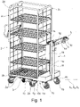
Fig. 1 ] représente une vue en perspective d'un ensemble de manutention comprenant un dispositif de manutention motorisé selon la présente invention et au moins un chariot, dans une configuration où le véhicule est accouplé avec un chariot à ridelles et étagères, - [
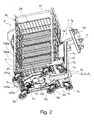
Fig. 2 ] montre l'ensemble représenté sur lafigure 1 , selon un autre angle de vue montrant le dessous de l'ensemble, - [
Fig. 3a ] représente une vue en coupe transversale partielle de l'ensemble représenté sur lafigure 1 au niveau de sa partie comprenant les moyens de verrouillage de l'accouplement, - [
Fig. 3b ] est une vue de détail des moyens de verrouillage de lafigure 3a , - [
Fig. 4 ] représente une vue partielle de l'ensemble représenté sur lafigure 2 au début de la phase d'emboîtement des premier et deuxième éléments d'accouplement, - [
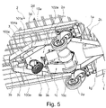
Fig. 5 ] montre l'ensemble représenté sur lafigure 4 dans une phase plus avancée de l'emboitement, - [
Fig. 6 ] montre l'ensemble représenté sur lafigure 5 à l'état partiellement emboîté du doigt de centrage et/ou d'accrochage dans le trou de centrage et/ou d'accrochage, - [
Fig. 7 ] montre l'ensemble représenté sur lafigure 6 à l'état emboîté des premier et deuxième éléments d'accouplement et à l'état emboîté du doigt de centrage et/ou d'accrochage.
- [
Fig. 1 ] shows a perspective view of a handling assembly comprising a motorized handling device according to the present invention and at least one trolley, in a configuration where the vehicle is coupled with a trolley with drop sides and shelves, - [
Fig. 2 ] shows the set represented on thefigure 1 , from another angle of view showing the underside of the assembly, - [
Fig. 3a ] shows a partial cross-sectional view of the assembly shown in thefigure 1 at its part comprising the coupling locking means, - [
Fig. 3b ] is a detail view of the locking means of thepicture 3a - [
Fig. 4 ] represents a partial view of the assembly represented on thepicture 2 - [
Fig. 5 ] shows the set represented on thefigure 4 in a more advanced phase of nesting, - [
Fig. 6 ] shows the set represented on thefigure 5 in the partially fitted state of the centering and/or attachment pin in the centering and/or attachment hole, - [
Fig. 7 ] shows the set represented on thefigure 6 in the nested state of the first and second coupling elements and in the nested state of the centering finger and / or attachment.
Les figures annexées montrent un dispositif de manutention motorisé, selon la présente invention, pour pousser et/ou tracter au moins un chariot, ledit dispositif comprenant un véhicule 1 motorisé pousseur et/ou tracteur s'étendant le long d'un axe longitudinal, dit premier axe longitudinal X1, et étant apte et destiné à être accouplé à un chariot 2 muni (ou monté sur) de roulettes 2a pour pousser ou tracter ce dernier. Le véhicule 1 comporte une base 1a montée sur des roulettes 1b et sur une unité de roue motorisée 1c, au moins une poignée de guidage 1d, des moyens de commande et/ou de contrôle 1h, 1i, 1j, 1k permettant la commande et/ou le contrôle de l'unité de roue motorisée 1c et une alimentation en énergie 1e du type batterie. La base 1a du véhicule 1 est apte et destinée à venir, au moins en partie, se positionner sous la base 2a d'un chariot 2 s'étendant le long d'un axe longitudinal, dit deuxième axe longitudinal X2, pour réaliser leur accouplement, c'est-à-dire l'accouplement dudit chariot 2 et dudit véhicule 1.The appended figures show a motorized handling device, according to the present invention, for pushing and/or towing at least one trolley, said device comprising a motorized pusher and/or
Conformément à la présente invention, un tel dispositif comprend en outre au moins un premier élément d'accouplement 3 femelle, respectivement mâle, s'étendant le long d'un axe longitudinal, dit troisième axe longitudinal X3, et étant apte et destiné à être fixé sous la base 2b d'un chariot 2 en étant centré sur le deuxième axe longitudinal X2 et un deuxième élément d'accouplement 10a mâle, respectivement femelle, formant une partie de la base 1a du véhicule 1 située à l'avant et centrée sur le premier axe longitudinal X1, lesdits premier et deuxième éléments d'accouplement 3, 10a étant de forme complémentaire et aptes à coopérer l'un avec l'autre par emboîtement mutuel pour être mis dans un état emboîté permettant d'accoupler le véhicule 1 avec un chariot 2 équipé d'un tel élément d'accouplement par emboîtement 3 et, éventuellement, des moyens de verrouillage 4 de l'accouplement.In accordance with the present invention, such a device further comprises at least one
De préférence, les roulettes 1b du véhicule sont pivotantes. De même, les roulettes 2a du chariot 2 sont préférentiellement pivotantes.Preferably, the
Si on se réfère notamment aux
On comprend que la présente invention peut prévoir deux formes de réalisation mâle/femelle pour l'emboîtement :
- l'une, représentée sur les figures annexées, dans laquelle le deuxième élément d'accouplement 10a monté sur le
véhicule 1 est mâle et le premier élément d'emboîtement 3 destiné à être monté sur unchariot 2 est femelle, - le cas échéant, l'autre, non représentée sur les figures annexées, dans laquelle le deuxième élément d'accouplement 10a monté sur le
véhicule 1 est femelle et le premier élément d'emboîtement 3 destiné à être monté sur unchariot 2 est mâle.
- one, shown in the appended figures, in which the
second coupling element 10a mounted on thevehicle 1 is male and the first interlockingelement 3 intended to be mounted on acarriage 2 is female, - where appropriate, the other, not shown in the appended figures, in which the
second coupling element 10a mounted on thevehicle 1 is female and the first interlockingelement 3 intended to be mounted on acarriage 2 is male.
Plus particulièrement, le deuxième élément d'accouplement 10a mâle, le cas échéant le premier élément d'accouplement 3 mâle, comprend une extrémité 100a d'emboîtement. En outre, le premier élément d'accouplement 3 femelle, le cas échéant le deuxième élément d'accouplement 10a femelle, comporte deux extrémités 3a, 3b opposées longitudinalement, à savoir une extrémité 3a ouverte apte à recevoir ladite extrémité 100a d'emboitement du deuxième élément d'accouplement 10a mâle, le cas échéant du premier élément d'accouplement mâle 3, en vue de réaliser l'emboîtement mutuel et une extrémité 3b de fond définissant intérieurement le fond de l'emboîtement.More particularly, the second
Dans une forme de réalisation préférentielle, le deuxième élément d'accouplement 10a mâle, le cas échéant le premier élément d'accouplement 3 mâle, comprend une partie d'extrémité 101a comportant l'extrémité 100a d'emboîtement et allant en se rétrécissant jusqu'à cette dernière ou étant évasée vers l'arrière depuis cette dernière (voir notamment les
De préférence, comme on peut le voir notamment sur les
L'unité motorisée 1c comprend au moins une roue 10c. La présente invention peut prévoir, de préférence, que la ou chaque roue 10c puisse être déplacée dans une position abaissée en contact avec le sol ou la surface sur laquelle se déplace le véhicule 1 et dans une position relevée ou la ou chaque roue 10c n'est plus en contact de frottements avec ledit sol ou ladite surface.Motorized
Dans un mode de réalisation préférentiel, selon une première forme de réalisation où le premier élément d'accouplement 3 est femelle comme on peut le voir notamment sur les
le premier élément d'accouplement 3 femelle, le cas échéant le deuxième élément d'accouplement 10a femelle, comporte un doigt de centrage et/ou d'accrochage 3c, de préférence de forme globalement cylindrique ou conique, fixé sur le fond de l'emboitement et centré sur le troisième axe longitudinal X3, le cas échéant sur le premier axe longitudinal X1, en s'étendant axialement vers l'extrémité 3a ouverte. En outre, l'extrémité 100a d'emboîtement du deuxième élément d'accouplement 10a mâle, le cas échéant du premier élément d'accouplement 3 mâle, comporte un trou de centrage et/ou d'accrochage 103a, centré sur le premier axe longitudinal X1, le cas échéant sur le troisième axe longitudinal X3. Le trou de centrage et/ou d'accrochage 103a est apte et destiné à recevoir ledit doigt de centrage et/ou d'accrochage 3c au moins à l'état d'accouplement (
the first
Toujours dans ce mode de réalisation, dans une forme non représentée sur les figures annexées, le premier élément d'accouplement 3 femelle, le cas échéant le deuxième élément d'accouplement 10a femelle, comporte un trou de centrage et/ou d'accrochage pratiquée dans le fond d'emboitement et centré sur le troisième axe longitudinal X3, le cas échéant sur le premier axe longitudinal X1, et en ce que l'extrémité 100a d'emboitement du deuxième élément d'accouplement 10a mâle, le cas échéant l'extrémité d'emboitement du premier élément d'accouplement 3 mâle, se prolonge extérieurement et axialement par un doigt de centrage et/ou d'accrochage, centré sur le premier axe longitudinal X1, le cas échéant sur le troisième axe longitudinal X3, ledit trou de centrage et/ou d'accrochage étant apte à recevoir ledit doigt de centrage et/ou d'accrochage à l'état d'accouplement.Still in this embodiment, in a form not shown in the appended figures, the first
De préférence, le deuxième élément d'accouplement 10a mâle, le cas échéant le premier élément d'accouplement 3 mâle, présente une face inférieure 104a et porte l'unité de roue motorisée 1c qui est montée sur ladite face inférieure 104a.Preferably, the second
Dans une forme préférentielle de la partie arrière du véhicule, le véhicule 1 comprend à l'arrière un montant 1f comportant une extrémité inférieure fixée sur la base 1a et une extrémité supérieure comportant un bras 1g du type guidon de direction portant la ou les poignées de guidage 1d, de préférence deux poignées de guidage. De préférence, le montant 1f peut supporter l'alimentation en énergie 1e du type batterie. De préférence, un tel montant 1f est dans une position centrale à l'arrière du véhicule 1, c'est à dire en s'étendant verticalement dans le plan médian longitudinal dudit véhicule 1.In a preferred form of the rear part of the vehicle, the
Si on se réfère notamment aux
Dans une forme préférentielle, comme on peut le voir notamment sur les
Dans une forme préférentielle de leur réalisation, le premier élément d'accouplement 3 et le deuxième élément d'accouplement 10a, dans leur forme mâle ou femelle, peuvent être réalisés à partir d'un assemblage de fer plats.In a preferred embodiment, the
De préférence, le premier élément d'accouplement 3 et le deuxième élément d'accouplement 10a présentent une forme de cadre. Un tel cadre peut présenter, de préférence, l'une des formes prismatiques précitées. Un tel cadre est ouvert sur au moins l'un de ses côtés pour former l'extrémité 3a ouverte (voir
Selon une caractéristique additionnelle, le véhicule 1 peut comprendre en outre au moins deux pattes de centrage 1g évasées vers l'avant et disposés de chaque côté de la base 1a dudit véhicule 1, de préférence vers l'arrière dudit véhicule 1 (voir notamment les
Si on se réfère maintenant aux
De préférence, le loquet 4a peut être assujetti à ou précontraint par un ressort le rappelant dans l'une de ses positions, par exemple dans sa position relevée. Le passage de sa position relevée à sa position escamotée peut alors être réalisée par l'utilisateur actionnant l'organe de commande 4c. En outre le loquet 4a, comme on peut le voir sur les
La présente invention a également pour objet un ensemble de manutention comprenant un dispositif de manutention motorisé et au moins un chariot 2.The present invention also relates to a handling assembly comprising a motorized handling device and at least one
Toujours conformément à la présente invention, dans un tel ensemble, ledit dispositif de manutention motorisé consiste en un dispositif de manutention motorisé selon la présente invention. En outre, le ou le ou chaque premier élément d'accouplement 3 femelle, respectivement mâle, est fixé sous la base 2b du ou de l'un des chariot(s) 2 en étant centré sur l'axe longitudinal X2 dudit chariot 2.Still in accordance with the present invention, in such an assembly, said motorized handling device consists of a handling device motorized according to the present invention. In addition, the or the or each first female, respectively male,
Comme on peut le voir notamment sur les
De préférence, à l'état accouplé, comme on peut le voir notamment sur les
Dans le cas, le plus courant, d'un chariot 2 comprenant quatre roulettes 2a, l'insertion de la base 1a du véhicule 1 sous la base 2b du chariot 2 pour leur accouplement est réalisée entre les deux roulettes 2a situées sur le côté du chariot 2, dit côté d'accouplement, prévu pour réaliser l'accouplement. L'extrémité 3a ouverte, le cas échéant l'extrémité d'emboitement, du premier élément d'accouplement 3 femelle, le cas échéant mâle, est alors orientée vers ledit côté d'accouplement du chariot 2. La largeur du premier élément d'emboitement 10a mâle, respectivement femelle, est donc déterminée de sorte à permettre l'insertion entre les deux roulettes 2a dudit côté d'emboitement du chariot 2. Dans le cas d'un chariot 2 de base 2b globalement rectangulaire, le côté d'accouplement est l'un des deux petits côtés opposés.In the most common case of a
Un tel dispositif selon la présente invention permet ainsi, notamment par une meilleure manoeuvrabilité, d'optimiser les mouvements de manutention et la sécurité de l'utilisateur en réduisant notablement les risques de blessure. En outre, la disposition des éléments d'accouplement sous le chariot 2 et le véhicule 1 permet également de limiter les risques de blessure par le fait qu'aucun élément blessant ne se trouve à portée de l'utilisateur et notamment de ses jambes. Une telle sécurité permet de réduire les arrêts de travail des manutentionnaires qui se multiplient avec les systèmes actuels et les rendements imposés.Such a device according to the present invention thus makes it possible, in particular through better manoeuvrability, to optimize the handling movements and the safety of the user by notably reducing the risk of injury. In Furthermore, the arrangement of the coupling elements under the
Bien entendu, l'invention n'est pas limitée au mode de réalisation décrit et représenté aux dessins annexés. Des modifications restent possibles, notamment du point de vue de la constitution des divers éléments ou par substitution d'équivalents techniques, sans sortir pour autant du domaine de protection de l'invention.Of course, the invention is not limited to the embodiment described and shown in the accompanying drawings. Modifications remain possible, in particular from the point of view of the constitution of the various elements or by substitution of technical equivalents, without thereby departing from the scope of protection of the invention.
Claims (14)
Priority Applications (1)
| Application Number | Priority Date | Filing Date | Title |
|---|---|---|---|
| EP21315023.8A EP4046891A1 (en) | 2021-02-19 | 2021-02-19 | Motorised handling device for pushing and/or towing at least one carriage and handling assembly comprising such a device |
Applications Claiming Priority (1)
| Application Number | Priority Date | Filing Date | Title |
|---|---|---|---|
| EP21315023.8A EP4046891A1 (en) | 2021-02-19 | 2021-02-19 | Motorised handling device for pushing and/or towing at least one carriage and handling assembly comprising such a device |
Publications (1)
| Publication Number | Publication Date |
|---|---|
| EP4046891A1 true EP4046891A1 (en) | 2022-08-24 |
Family
ID=74859870
Family Applications (1)
| Application Number | Title | Priority Date | Filing Date |
|---|---|---|---|
| EP21315023.8A Withdrawn EP4046891A1 (en) | 2021-02-19 | 2021-02-19 | Motorised handling device for pushing and/or towing at least one carriage and handling assembly comprising such a device |
Country Status (1)
| Country | Link |
|---|---|
| EP (1) | EP4046891A1 (en) |
Cited By (1)
| Publication number | Priority date | Publication date | Assignee | Title |
|---|---|---|---|---|
| FR3146449A1 (en) * | 2023-03-07 | 2024-09-13 | Renault | Device for assisting in moving a trolley and corresponding moving method |
Citations (5)
| Publication number | Priority date | Publication date | Assignee | Title |
|---|---|---|---|---|
| US20110266078A1 (en) * | 2010-04-30 | 2011-11-03 | Caterpillar Inc. | Order picking cart for stock chaser vehicle |
| DE102012108118A1 (en) * | 2012-08-31 | 2014-03-06 | Hupfer Metallwerke Gmbh & Co. Kg | Drive for e.g. trolley utilized for transportation and distribution of food in hospital, has load-carrying portion with lifting device, and coupling unit arranged in lifting device for providing detachable connection to underside of trolley |
| US20180304912A1 (en) | 2008-05-14 | 2018-10-25 | Dane Technologies, Inc. | Cart Pusher, Mateable Carts, and Related Systems, Methods, and Devices |
| CN109987123A (en) * | 2018-01-03 | 2019-07-09 | 均豪精密工业股份有限公司 | automatic handling vehicle |
| US20190270472A1 (en) * | 2016-07-29 | 2019-09-05 | Nidec-Shimpo Corporation | Automatic guided vehicle and method for controlling automatic guided vehicle |
-
2021
- 2021-02-19 EP EP21315023.8A patent/EP4046891A1/en not_active Withdrawn
Patent Citations (5)
| Publication number | Priority date | Publication date | Assignee | Title |
|---|---|---|---|---|
| US20180304912A1 (en) | 2008-05-14 | 2018-10-25 | Dane Technologies, Inc. | Cart Pusher, Mateable Carts, and Related Systems, Methods, and Devices |
| US20110266078A1 (en) * | 2010-04-30 | 2011-11-03 | Caterpillar Inc. | Order picking cart for stock chaser vehicle |
| DE102012108118A1 (en) * | 2012-08-31 | 2014-03-06 | Hupfer Metallwerke Gmbh & Co. Kg | Drive for e.g. trolley utilized for transportation and distribution of food in hospital, has load-carrying portion with lifting device, and coupling unit arranged in lifting device for providing detachable connection to underside of trolley |
| US20190270472A1 (en) * | 2016-07-29 | 2019-09-05 | Nidec-Shimpo Corporation | Automatic guided vehicle and method for controlling automatic guided vehicle |
| CN109987123A (en) * | 2018-01-03 | 2019-07-09 | 均豪精密工业股份有限公司 | automatic handling vehicle |
Cited By (1)
| Publication number | Priority date | Publication date | Assignee | Title |
|---|---|---|---|---|
| FR3146449A1 (en) * | 2023-03-07 | 2024-09-13 | Renault | Device for assisting in moving a trolley and corresponding moving method |
Similar Documents
| Publication | Publication Date | Title |
|---|---|---|
| EP0511113B1 (en) | Personal vehicle usable in a handpropelled or motorised mode, especially a wheelchair or tricycle | |
| CA2390320C (en) | Coupling device for industrial truck | |
| FR3100527A1 (en) | Electric vehicle | |
| EP1447301B1 (en) | Pushchair with control means for locking and unlocking the brakes, said means being apart and in the vicinty of each other | |
| EP2540530B1 (en) | Trailer train | |
| EP4046891A1 (en) | Motorised handling device for pushing and/or towing at least one carriage and handling assembly comprising such a device | |
| FR2581965A1 (en) | SELF-PROPELLED-TRACTOR HANDLE | |
| EP4157188B1 (en) | Removable electronic propulsion system for a rolling object with an automatic directional blocking means | |
| WO2021190952A1 (en) | Removable electric propulsion system for a rolling object with a device for releasing the handlebar | |
| EP1927525B1 (en) | Mobile part supply unit for supplying production lines | |
| FR3037310A1 (en) | TRAILER COMPRISING A MEANS OF IMMOBILIZATION, VEHICLE COMMANDING THE REVERSIBLE IMMOBILIZATION AND HITCHING OF THE TRAILER, TOGETHER FORMED BY THE COUPLING OF SUCH A TRAILER AND SUCH A VEHICLE | |
| EP0728600A1 (en) | Device with a recractable hook for towing vehicles | |
| FR2979609A1 (en) | Trailer for use in storage warehouse supermarket for transportation of trolleys, has lifting unit interposed between frame and rolling unit to lift frame from lowered position by rolling up to high position for transportation of trolleys | |
| FR2876957A1 (en) | HITCHING TIMON FOR HANDLING TROLLEY AND HITCHING DEVICE INCORPORATING IT | |
| FR3149544A1 (en) | COUPLING DEVICE CONFIGURED TO ATTACH TO A MOBILE CART AND ROBOTIC DRIVE SYSTEM FOR AT LEAST ONE MOBILE CART COMPRISING SUCH A COUPLING DEVICE | |
| FR2690123A1 (en) | Motorised trolley for pallets steered by pedestrian at side - has central driven and steered wheel with two side castering wheels under a central unit with rollers under the fork ends | |
| WO2025210311A1 (en) | Robotic drive system for at least one mobile cart | |
| FR2490173A1 (en) | Trolley for transporting documents - has wheeled frame with open containers sliding sideways and controlled by stop-grips | |
| WO2020187516A1 (en) | Device for lifting a wheel of a removable electric drive system for a rolling object | |
| FR2749803A1 (en) | Trailer for the transport of agricultural implement | |
| EP4125763A1 (en) | Removable electric propulsion system for a rolling object with a device for releasing the handlebar | |
| FR2582607A1 (en) | Trolley for transporting merchandise, especially in supermarkets, equipped with a two-part deposit device | |
| FR2624466A1 (en) | Self-propelled multi-use trolley | |
| CA3036606C (en) | Pushchair accessory, and a transport assembly comprising a pushchair and such an accessory | |
| EP1773620A1 (en) | Device for facilitating loading of a container on a platform |
Legal Events
| Date | Code | Title | Description |
|---|---|---|---|
| PUAI | Public reference made under article 153(3) epc to a published international application that has entered the european phase |
Free format text: ORIGINAL CODE: 0009012 |
|
| STAA | Information on the status of an ep patent application or granted ep patent |
Free format text: STATUS: THE APPLICATION HAS BEEN PUBLISHED |
|
| AK | Designated contracting states |
Kind code of ref document: A1 Designated state(s): AL AT BE BG CH CY CZ DE DK EE ES FI FR GB GR HR HU IE IS IT LI LT LU LV MC MK MT NL NO PL PT RO RS SE SI SK SM TR |
|
| STAA | Information on the status of an ep patent application or granted ep patent |
Free format text: STATUS: REQUEST FOR EXAMINATION WAS MADE |
|
| 17P | Request for examination filed |
Effective date: 20230223 |
|
| RBV | Designated contracting states (corrected) |
Designated state(s): AL AT BE BG CH CY CZ DE DK EE ES FI FR GB GR HR HU IE IS IT LI LT LU LV MC MK MT NL NO PL PT RO RS SE SI SK SM TR |
|
| STAA | Information on the status of an ep patent application or granted ep patent |
Free format text: STATUS: THE APPLICATION IS DEEMED TO BE WITHDRAWN |
|
| 18D | Application deemed to be withdrawn |
Effective date: 20240903 |