EP4046891A1 - Motorisierte fördervorrichtung zum schieben und/oder ziehen mindestens eines wagens und förderanordnung mit einer solchen vorrichtung - Google Patents
Motorisierte fördervorrichtung zum schieben und/oder ziehen mindestens eines wagens und förderanordnung mit einer solchen vorrichtung Download PDFInfo
- Publication number
- EP4046891A1 EP4046891A1 EP21315023.8A EP21315023A EP4046891A1 EP 4046891 A1 EP4046891 A1 EP 4046891A1 EP 21315023 A EP21315023 A EP 21315023A EP 4046891 A1 EP4046891 A1 EP 4046891A1
- Authority
- EP
- European Patent Office
- Prior art keywords
- coupling element
- longitudinal axis
- motorized
- vehicle
- carriage
- Prior art date
- Legal status (The legal status is an assumption and is not a legal conclusion. Google has not performed a legal analysis and makes no representation as to the accuracy of the status listed.)
- Withdrawn
Links
Images


Classifications
-
- B—PERFORMING OPERATIONS; TRANSPORTING
- B62—LAND VEHICLES FOR TRAVELLING OTHERWISE THAN ON RAILS
- B62B—HAND-PROPELLED VEHICLES, e.g. HAND CARTS OR PERAMBULATORS; SLEDGES
- B62B3/00—Hand carts having more than one axis carrying transport wheels; Steering devices therefor; Equipment therefor
- B62B3/04—Hand carts having more than one axis carrying transport wheels; Steering devices therefor; Equipment therefor involving means for grappling or securing in place objects to be carried; Loading or unloading equipment
-
- B—PERFORMING OPERATIONS; TRANSPORTING
- B62—LAND VEHICLES FOR TRAVELLING OTHERWISE THAN ON RAILS
- B62B—HAND-PROPELLED VEHICLES, e.g. HAND CARTS OR PERAMBULATORS; SLEDGES
- B62B5/00—Accessories or details specially adapted for hand carts
- B62B5/0026—Propulsion aids
-
- B—PERFORMING OPERATIONS; TRANSPORTING
- B62—LAND VEHICLES FOR TRAVELLING OTHERWISE THAN ON RAILS
- B62B—HAND-PROPELLED VEHICLES, e.g. HAND CARTS OR PERAMBULATORS; SLEDGES
- B62B5/00—Accessories or details specially adapted for hand carts
- B62B5/0026—Propulsion aids
- B62B5/0033—Electric motors
-
- B—PERFORMING OPERATIONS; TRANSPORTING
- B62—LAND VEHICLES FOR TRAVELLING OTHERWISE THAN ON RAILS
- B62B—HAND-PROPELLED VEHICLES, e.g. HAND CARTS OR PERAMBULATORS; SLEDGES
- B62B5/00—Accessories or details specially adapted for hand carts
- B62B5/0026—Propulsion aids
- B62B5/0079—Towing by connecting to another vehicle
Definitions
- the present invention relates to the field of handling and relates to a motorized handling device for pushing and/or towing at least one trolley. It also relates to a handling assembly comprising such a device.
- trolleys In the field of handling and transport, trolleys are already known, generally equipped with fixed wheels and/or swivel wheels, making it possible to transport heavy or less heavy loads of different sizes on all types of floors in complete safety.
- trolleys with or without drop sides, removable or fixed or even trolleys with a tray or shelves above said tray.
- carriages are pushed or towed manually by a user from one point to another and certain carriages benefit from motorization making it possible to assist the pushing or pulling by the user.
- motor-assisted trucks some are self-propelled, i.e. they have their own motorization and motorization control, and others are adapted to be coupled to a pusher/tractor equipped with motorization and its control.
- the pusher/tractor is generally designed to push or tow a single carriage coupled to the latter or a train of carriages, the first carriage of which is coupled to said pusher/tractor.
- Such cart(s) pusher/tractor is disclosed by document US2018/0304912 .
- the motorized pushing device comprises a base in the form of a tray mounted on four swivel castors, two front castors and two rear castors, a motor located under said base and coupled to said front wheels, a right control handle and a left control handle, a guide handle and a battery supplying the motor.
- the trolley has a base in the form of a tray mounted on four external pivoting wheels and two central guide wheels capable of being lowered to be in contact with the ground or raised.
- the base of the motorized pushing device is located at a height above the ground, i.e.
- the carriage further comprises at the rear of the base a coupling bar allowing its coupling with the motorized pushing device using latches or bolts mounted at the rear of the base of said device.
- a motorized pushing device of the type disclosed by the document US2018/0304912 does not have sufficient technical qualities to give it, in particular, good maneuverability and/or sufficient safety of use.
- the object of the present invention is to overcome these drawbacks by proposing a motorized handling device for pushing and/or towing at least one transport carriage, which is more maneuverable than the current devices, while improving the safety of the user.
- the motorized handling device for pushing and/or towing at least one trolley, said device comprising a motorized pushing and/or tractor vehicle extending along a longitudinal axis, called the first longitudinal axis, and being adapted and intended to be coupled to a trolley provided with castors for pushing or towing the latter, said vehicle comprising a base mounted on castors and on a motorized wheel unit, at least one guide handle, means command and/or control allowing the command and/or the control of the motorized wheel unit and a power supply of the battery type, said base of the vehicle being adapted and intended to come, at least in part, to be positioned under the base of a carriage extending along a longitudinal axis, said second longitudinal axis, to achieve their coupling, is essentially characterized in that it further comprises at least a first coupling element fe melle, respectively male, extending along a longitudinal axis, called the third longitudinal axis, and being suitable and intended to be fixed under the base of a trolley
- the present invention also relates to a handling assembly comprising a motorized handling device and at least one carriage, characterized in that said motorized handling device consists of a motorized handling device according to the present invention and in that the or each first female coupling element, respectively male, is fixed under the base of the or one of the carriage(s) being centered on the longitudinal axis of the said carriage.
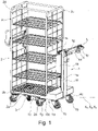
- the appended figures show a motorized handling device, according to the present invention, for pushing and/or towing at least one trolley, said device comprising a motorized pusher and/or tractor vehicle 1 extending along a longitudinal axis, called first longitudinal axis X1, and being able and intended to be coupled to a carriage 2 provided with (or mounted on) wheels 2a to push or tow the latter.
- the vehicle 1 comprises a base 1a mounted on rollers 1b and on a motorized wheel unit 1c, at least one guide handle 1d, command and/or control means 1h, 1i, 1j, 1k allowing the command and/or or controlling the motorized wheel unit 1c and a battery type power supply 1e.
- the base 1a of the vehicle 1 is able and intended to come, at least in part, to be positioned under the base 2a of a carriage 2 extending along a longitudinal axis, said second longitudinal axis X2, to achieve their coupling , that is to say the coupling of said carriage 2 and said vehicle 1.
- such a device further comprises at least one first coupling element 3 female, respectively male, extending along a longitudinal axis, called third longitudinal axis X3, and being able and intended to be fixed under the base 2b of a carriage 2 being centered on the second longitudinal axis X2 and a second male, respectively female coupling element 10a, forming a part of the base 1a of the vehicle 1 located at the front and centered on the first longitudinal axis X1, said first and second coupling elements 3, 10a being of complementary shape and capable of cooperating with each other by mutual interlocking to be placed in a nested state allowing the vehicle 1 to be coupled with a trolley 2 equipped with such a coupling element coupling by interlocking 3 and, possibly, locking means 4 of the coupling.
- the wheels 1b of the vehicle are pivoting.
- the rollers 2a of the carriage 2 are preferably pivoting.
- carriage 2 equipped with a coupling element by interlocking 3 can be for example a carriage 2 with sides 2c, fixed or removable. It can also be seen that such a carriage 2 can be provided to include one or more shelves 2d.
- Other types of carriages 2, not shown in the appended figures, can be provided to be equipped with a coupling element by interlocking 3 according to the present invention such as carriages 2 without sides, that is to say only with a plate forming at least part of the base 2b.
- the second male coupling element 10a where applicable the first male coupling element 3, comprises a nesting end 100a.
- the first female coupling element 3, where appropriate the second female coupling element 10a comprises two longitudinally opposite ends 3a, 3b, namely an open end 3a adapted to receive said end 100a for fitting the second male coupling element 10a, if applicable of the first coupling element male 3, in order to achieve mutual interlocking and a bottom end 3b internally defining the bottom of the interlocking.
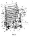
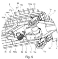
- the second male coupling element 10a where appropriate the first male coupling element 3, comprises an end part 101a comprising the nesting end 100a and tapering to to the latter or being flared towards the rear from the latter (see in particular the figure 2 , 4 , 5 , 6 and 7 ).
- the end part 101a is in the shape of a flared U and the interlocking end 100a forms the base of said U.
- the second male coupling element 10a where appropriate the first male coupling element 3 has a central guide part extending said end part 101a behind the latter and being delimited laterally by two guide sides 102a lateral located on either side of the first longitudinal axis X1, if necessary of the third longitudinal axis X3.
- said lateral guide sides 102a extend parallel to said first longitudinal axis X1, where applicable to said third longitudinal axis X3.
- Motorized unit 1c includes at least one wheel 10c.
- the present invention can provide, preferably, that the or each wheel 10c can be moved into a lowered position in contact with the ground or the surface on which the vehicle 1 is moving and into a raised position where the or each wheel 10c is not is more in frictional contact with said ground or said surface.
- the first female coupling element 3 where applicable the second female coupling element 10a, comprises a centering and/or latching finger 3c, preferably of generally cylindrical or conical shape, fixed to the bottom of the interlocking and centered on the third longitudinal axis X3, if necessary on the first longitudinal axis X1, extending axially towards the open end 3a.
- the nesting end 100a of the second male coupling element 10a if applicable of the first male coupling element 3, comprises a centering and/or hooking hole 103a, centered on the first longitudinal axis X1, if necessary on the third longitudinal axis X3.
- the centering and/or attachment hole 103a is suitable and intended to receive said centering and/or attachment pin 3c at least in the coupling state ( figure 2 , 6 and 7 ).
- the first female coupling element 3, where appropriate the second female coupling element 10a comprises a centering and/or hooking hole made in the interlocking bottom and centered on the third longitudinal axis X3, where applicable on the first longitudinal axis X1, and in that the interlocking end 100a of the second male coupling element 10a, where applicable the fitting end of the first male coupling element 3, is extended externally and axially by a centering and/or hooking finger, centered on the first longitudinal axis X1, where appropriate on the third longitudinal axis X3, said hole centering and / or attachment being adapted to receive said centering pin and / or attachment in the coupling state.
- the second male coupling element 10a if necessary the first male coupling element 3, has a lower face 104a and carries the motorized wheel unit 1c which is mounted on said lower face 104a.
- the vehicle 1 comprises at the rear an upright 1f comprising a lower end fixed to the base 1a and an upper end comprising an arm 1g of the steering handlebar type carrying the steering handle(s). 1d guide, preferably two guide handles.
- the upright 1f can support the battery-type power supply 1e.
- such an upright 1f is in a central position at the rear of the vehicle 1, that is to say extending vertically in the longitudinal median plane of said vehicle 1.
- control and/or control means 1h, 1i, 1d, 1k can comprise, for example, a control box 1h and a control button 1i.
- the control box 1h is operatively connected to the motorized wheel unit 1c and to said control button 1i and can be mounted on the upright 1f.
- the control box 1h can comprise a box containing an electronic card comprising the command and control parameters such as the speed and the motor torque of the motorized wheel unit 1c.
- the control button 1i makes it possible, for example, to control the speed, preferably gradually and/or the forward or reverse gear.
- the speed can be set in the control box 1h so as not to exceed a programmed maximum speed when the control button 1i is actuated.
- control button 1i can be mounted in the or one of the guide handle(s) 1d, for example at the end of the latter, for example in a manner similar to an accelerator button of a handle of throttle lever for moped or motorcycle.
- the command and control means 1h, 1i, 1d, 1k can also comprise a display screen 1d making it possible to display, for example, the speed, the forward or reverse gear or any other parameter relating to the command and control of the motorized wheel unit 1c and of the vehicle 1.
- the command and control means 1h, 1i, 1j, 1k can also comprise a removable storage medium 1k, such as a USB key , making it possible to modify and/or program the control/piloting parameters such as the speed and/or the torque, in particular the torque at start-up and/or while driving.
- a storage medium 1k can be inserted into the control box 1h.
- Such a 1k storage medium can also be a portable storage medium 1k of the tablet or smartphone type or a computer capable of communicating, for example by electric wire or radio waves, with the control box 1h to exchange with the latter, configured for this purpose, information and/ or files containing in particular the aforementioned adjustment parameters.
- the second male coupling element 10a if necessary the first male coupling element 3, generally has the shape of a rectangular, hexagonal or octagonal prism, or a part of said shape.
- the first female coupling element 3, where appropriate the second female coupling element 10a may have a similar shape, that is to say a rectangular, hexagonal or octagonal prism, or a part of said form.
- first coupling element 3 and the second coupling element 10a in their male or female form, can be made from an assembly of flat bars.
- the first coupling element 3 and the second coupling element 10a have a frame shape.
- a frame can preferably have one of the aforementioned prismatic shapes.
- Such a frame is open on at least one of its sides to form the open end 3a (see figure 4 notably).
- the vehicle 1 can also comprise at least two centering lugs 1g flared forwards and arranged on each side of the base 1a of said vehicle 1, preferably towards the rear of said vehicle 1 (see in particular the figure 1 , 2 , 4 , 5 , 6 and 7 ). These 1g centering lugs make it easier to guide during insertion for interlocking ( figure 1 , 2 , 5 , 6 and 7 ).
- the locking means 4 comprise at least one locking latch 4a mounted on or in the base 1a of the vehicle 1 and a locking bar 4b intended to be mounted, or being integrated , in a carriage 2 intended to be coupled to said vehicle 1, said locking bar 4b extending, that is to say in the mounted or integrated state in said carriage 2, perpendicular to its longitudinal axis X2.
- the or each latch 4a is mobile in displacement, preferably by pivoting around an axis 40a perpendicular to the first longitudinal axis X1, between a retracted position ensuring unlocking by extending under said locking bar 4b at the coupling state and a raised locking position coming against the locking bar in front of the latter in the coupling state.
- the locking means comprise control and connection means 4c making it possible to actuate the movement of said latch or latches 4a.
- the control and connection means 4c may comprise a control member 4c operable by the user and a connection mechanism functionally connecting said control member 4c to said latch(s) 4a.
- the control member 4c can have, for example, the shape of a pedal, for example U-shaped, preferably placed at the base of the vehicle 1, preferably at the rear of the latter, so as to be operable by the foot of the user maneuvering said vehicle 1.
- the latch 4a may be subject to or prestressed by a spring recalling it to one of its positions, for example to its raised position. The passage from its raised position to its retracted position can then be performed by the user actuating the control member 4c.
- the latch 4a as can be seen on the figure 4a can be configured so that, the latch 4a placed in the raised state under the stress of the spring, encounters, during the coupling phase, under the effect of the relative movement of the vehicle 1 with respect to the carriage 2, the bar locking bar 4b which then exerts on the latch 4a a downward thrust towards its retracted position until the locking bar 4b has passed the latch(s) 4a which is then no longer in contact with the bar locking 4b and is returned (s) automatically by the spring in its raised position ensuring the locking.
- the latch 4a prevents any movement of the locking bar 2 in the opposite direction.
- the present invention also relates to a handling assembly comprising a motorized handling device and at least one carriage 2.
- said motorized handling device consists of a handling device motorized according to the present invention.
- the or the or each first female, respectively male, coupling element 3 is fixed under the base 2b of the or one of the carriage(s) 2, being centered on the longitudinal axis X2 of the said carriage 2.
- the motorized handling device is coupled with the or one of the carriage(s) 2, called coupled carriage 2, the first coupling element 3 of said coupled carriage 2 cooperating by mutual interlocking with the second element coupling 10a of the vehicle 1.
- the locking means 4 ensure the locking of the coupling.
- the first, second and third longitudinal axes X1, X2, X3 are substantially coincident.
- their respective longitudinal axes X2, X3 preferably coincide substantially or form a common longitudinal axis. This feature makes it possible in particular to obtain a unitary assembly or a motorized block allowing movement with great stability.
- the insertion of the base 1a of the vehicle 1 under the base 2b of the carriage 2 for their coupling is carried out between the two rollers 2a located on the side of the carriage 2, said coupling side, provided to perform the coupling.
- the open end 3a, where appropriate the interlocking end, of the first coupling element 3 female, male where appropriate, is then oriented towards said coupling side of the carriage 2.
- the width of the first element of interlocking 10a male, respectively female, is therefore determined so as to allow insertion between the two rollers 2a of said interlocking side of the carriage 2.
- the coupling side is one of the two opposite short sides.
- Such a device according to the present invention thus makes it possible, in particular through better manoeuvrability, to optimize the handling movements and the safety of the user by notably reducing the risk of injury.
- the arrangement of the coupling elements under the carriage 2 and the vehicle 1 also makes it possible to limit the risk of injury by the fact that no injurious element is within reach of the user and in particular of his legs.
- Such safety makes it possible to reduce work stoppages for handlers, which are increasing with current systems and the imposed yields.
Landscapes
- Engineering & Computer Science (AREA)
- Chemical & Material Sciences (AREA)
- Combustion & Propulsion (AREA)
- Transportation (AREA)
- Mechanical Engineering (AREA)
- Handcart (AREA)
Priority Applications (1)
| Application Number | Priority Date | Filing Date | Title |
|---|---|---|---|
| EP21315023.8A EP4046891A1 (de) | 2021-02-19 | 2021-02-19 | Motorisierte fördervorrichtung zum schieben und/oder ziehen mindestens eines wagens und förderanordnung mit einer solchen vorrichtung |
Applications Claiming Priority (1)
| Application Number | Priority Date | Filing Date | Title |
|---|---|---|---|
| EP21315023.8A EP4046891A1 (de) | 2021-02-19 | 2021-02-19 | Motorisierte fördervorrichtung zum schieben und/oder ziehen mindestens eines wagens und förderanordnung mit einer solchen vorrichtung |
Publications (1)
| Publication Number | Publication Date |
|---|---|
| EP4046891A1 true EP4046891A1 (de) | 2022-08-24 |
Family
ID=74859870
Family Applications (1)
| Application Number | Title | Priority Date | Filing Date |
|---|---|---|---|
| EP21315023.8A Withdrawn EP4046891A1 (de) | 2021-02-19 | 2021-02-19 | Motorisierte fördervorrichtung zum schieben und/oder ziehen mindestens eines wagens und förderanordnung mit einer solchen vorrichtung |
Country Status (1)
| Country | Link |
|---|---|
| EP (1) | EP4046891A1 (de) |
Cited By (1)
| Publication number | Priority date | Publication date | Assignee | Title |
|---|---|---|---|---|
| FR3146449A1 (fr) * | 2023-03-07 | 2024-09-13 | Renault | Dispositif d’aide au déplacement d’un chariot et procédé de déplacement correspondant |
Citations (5)
| Publication number | Priority date | Publication date | Assignee | Title |
|---|---|---|---|---|
| US20110266078A1 (en) * | 2010-04-30 | 2011-11-03 | Caterpillar Inc. | Order picking cart for stock chaser vehicle |
| DE102012108118A1 (de) * | 2012-08-31 | 2014-03-06 | Hupfer Metallwerke Gmbh & Co. Kg | Fahrantrieb für Rollwagen, insbesondere Rollwagen für die Ausgabe, den Transport oder die Verteilung von Speisen |
| US20180304912A1 (en) | 2008-05-14 | 2018-10-25 | Dane Technologies, Inc. | Cart Pusher, Mateable Carts, and Related Systems, Methods, and Devices |
| CN109987123A (zh) * | 2018-01-03 | 2019-07-09 | 均豪精密工业股份有限公司 | 自动搬运载具 |
| US20190270472A1 (en) * | 2016-07-29 | 2019-09-05 | Nidec-Shimpo Corporation | Automatic guided vehicle and method for controlling automatic guided vehicle |
-
2021
- 2021-02-19 EP EP21315023.8A patent/EP4046891A1/de not_active Withdrawn
Patent Citations (5)
| Publication number | Priority date | Publication date | Assignee | Title |
|---|---|---|---|---|
| US20180304912A1 (en) | 2008-05-14 | 2018-10-25 | Dane Technologies, Inc. | Cart Pusher, Mateable Carts, and Related Systems, Methods, and Devices |
| US20110266078A1 (en) * | 2010-04-30 | 2011-11-03 | Caterpillar Inc. | Order picking cart for stock chaser vehicle |
| DE102012108118A1 (de) * | 2012-08-31 | 2014-03-06 | Hupfer Metallwerke Gmbh & Co. Kg | Fahrantrieb für Rollwagen, insbesondere Rollwagen für die Ausgabe, den Transport oder die Verteilung von Speisen |
| US20190270472A1 (en) * | 2016-07-29 | 2019-09-05 | Nidec-Shimpo Corporation | Automatic guided vehicle and method for controlling automatic guided vehicle |
| CN109987123A (zh) * | 2018-01-03 | 2019-07-09 | 均豪精密工业股份有限公司 | 自动搬运载具 |
Cited By (1)
| Publication number | Priority date | Publication date | Assignee | Title |
|---|---|---|---|---|
| FR3146449A1 (fr) * | 2023-03-07 | 2024-09-13 | Renault | Dispositif d’aide au déplacement d’un chariot et procédé de déplacement correspondant |
Similar Documents
| Publication | Publication Date | Title |
|---|---|---|
| EP0511113B1 (de) | Individuelles Fahrzeug verwendbar in einer handbedienende oder motorisierten Weise, besonders für einen Rollstuhl oder Dreirad | |
| CA2390320C (fr) | Dispositif d'attelage pour chariot de manutention | |
| FR3100527A1 (fr) | Véhicule électrique | |
| EP1447301B1 (de) | Kinderwagen mit Steuermittel zum Ver- und Entriegeln von Bremsanlagen, diese Mittel sind getrennt und in Nähe voneinander | |
| EP2540530B1 (de) | Lastzug | |
| EP4046891A1 (de) | Motorisierte fördervorrichtung zum schieben und/oder ziehen mindestens eines wagens und förderanordnung mit einer solchen vorrichtung | |
| FR2581965A1 (fr) | Timon automoteur-tracteur pour avion | |
| EP4157188B1 (de) | Abnehmbares elektronisches antriebssystem für ein rollendes objekt mit automatischer richtungsblockierung | |
| WO2021190952A1 (fr) | Systeme de propulsion electrique amovible pour un objet roulant avec un dispositif d'effacement du guidon | |
| EP1927525B1 (de) | Zuführschlitten für Werkstücke zu Produktionslinien | |
| FR3037310A1 (fr) | Remorque comportant un moyen d'immobilisation, vehicule commandant l'immobilisation et l'attelage reversibles de la remorque, ensemble forme par l'attelage d'une telle remorque et d'un tel vehicule | |
| EP0728600A1 (de) | Vorrichtung mit einem zurückziehbaren Haken für das Abschleppen von Fahrzeugen | |
| FR2979609A1 (fr) | Remorque destinee au transport d'une pluralite de chariots equipes de roulettes, et dispositif de transport comprenant cette remorque | |
| FR2876957A1 (fr) | Timon d'attelage pour chariot de manutention et dispositif d'attelage l'incorporant | |
| FR3149544A1 (fr) | Dispositif d’attelage configure pour s’accrocher a un chariot mobile et systeme d’entrainement robotise d’au moins un chariot mobile comportant un tel dispositif d’attelage | |
| FR2690123A1 (fr) | Chariot à conducteur accompagnant, notamment chariot transpalette. | |
| WO2025210311A1 (fr) | Systeme d'entrainement robotise d'au moins un chariot mobile | |
| FR2490173A1 (fr) | Chariot pour le transport et la distribution de documents | |
| WO2020187516A1 (fr) | Dispositif de levage de roue de systeme de propulsion electrique amovible pour un objet roulant | |
| FR2749803A1 (fr) | Remorque pour le transport d'engins lourds et encombrants | |
| EP4125763A1 (de) | Abnehmbares elektrisches antriebssystem für ein rollendes objekt mit einer vorrichtung zur entriegelung des lenkers | |
| FR2582607A1 (fr) | Chariot pour le transport de marchandises, notamment dans les magasins a libre service, muni d'un dispositif de consigne en deux parties | |
| FR2624466A1 (fr) | Chariot automoteur a usages multiples | |
| CA3036606C (fr) | Accessoire pour poussette, ainsi qu'ensemble de transport comprenant une poussette et un tel accessoire | |
| EP1773620A1 (de) | Vorrichtung zur erleichterung der beladung eines behälters auf einer plattform |
Legal Events
| Date | Code | Title | Description |
|---|---|---|---|
| PUAI | Public reference made under article 153(3) epc to a published international application that has entered the european phase |
Free format text: ORIGINAL CODE: 0009012 |
|
| STAA | Information on the status of an ep patent application or granted ep patent |
Free format text: STATUS: THE APPLICATION HAS BEEN PUBLISHED |
|
| AK | Designated contracting states |
Kind code of ref document: A1 Designated state(s): AL AT BE BG CH CY CZ DE DK EE ES FI FR GB GR HR HU IE IS IT LI LT LU LV MC MK MT NL NO PL PT RO RS SE SI SK SM TR |
|
| STAA | Information on the status of an ep patent application or granted ep patent |
Free format text: STATUS: REQUEST FOR EXAMINATION WAS MADE |
|
| 17P | Request for examination filed |
Effective date: 20230223 |
|
| RBV | Designated contracting states (corrected) |
Designated state(s): AL AT BE BG CH CY CZ DE DK EE ES FI FR GB GR HR HU IE IS IT LI LT LU LV MC MK MT NL NO PL PT RO RS SE SI SK SM TR |
|
| STAA | Information on the status of an ep patent application or granted ep patent |
Free format text: STATUS: THE APPLICATION IS DEEMED TO BE WITHDRAWN |
|
| 18D | Application deemed to be withdrawn |
Effective date: 20240903 |