EP4046863A1 - Verfahren zum erkennen einer drehung eines teils des rumpfes eines insassen, der auf einem sitz sitzt - Google Patents
Verfahren zum erkennen einer drehung eines teils des rumpfes eines insassen, der auf einem sitz sitzt Download PDFInfo
- Publication number
- EP4046863A1 EP4046863A1 EP22156636.7A EP22156636A EP4046863A1 EP 4046863 A1 EP4046863 A1 EP 4046863A1 EP 22156636 A EP22156636 A EP 22156636A EP 4046863 A1 EP4046863 A1 EP 4046863A1
- Authority
- EP
- European Patent Office
- Prior art keywords
- capacitive
- seat
- capacitive sensor
- occupant
- pico farads
- Prior art date
- Legal status (The legal status is an assumption and is not a legal conclusion. Google has not performed a legal analysis and makes no representation as to the accuracy of the status listed.)
- Granted
Links
Images
Classifications
-
- B—PERFORMING OPERATIONS; TRANSPORTING
- B60—VEHICLES IN GENERAL
- B60R—VEHICLES, VEHICLE FITTINGS, OR VEHICLE PARTS, NOT OTHERWISE PROVIDED FOR
- B60R21/00—Arrangements or fittings on vehicles for protecting or preventing injuries to occupants or pedestrians in case of accidents or other traffic risks
- B60R21/01—Electrical circuits for triggering passive safety arrangements, e.g. airbags, safety belt tighteners, in case of vehicle accidents or impending vehicle accidents
- B60R21/015—Electrical circuits for triggering passive safety arrangements, e.g. airbags, safety belt tighteners, in case of vehicle accidents or impending vehicle accidents including means for detecting the presence or position of passengers, passenger seats or child seats, and the related safety parameters therefor, e.g. speed or timing of airbag inflation in relation to occupant position or seat belt use
- B60R21/01512—Passenger detection systems
- B60R21/0153—Passenger detection systems using field detection presence sensors
- B60R21/01532—Passenger detection systems using field detection presence sensors using electric or capacitive field sensors
-
- B—PERFORMING OPERATIONS; TRANSPORTING
- B60—VEHICLES IN GENERAL
- B60Q—ARRANGEMENT OF SIGNALLING OR LIGHTING DEVICES, THE MOUNTING OR SUPPORTING THEREOF OR CIRCUITS THEREFOR, FOR VEHICLES IN GENERAL
- B60Q9/00—Arrangement or adaptation of signal devices not provided for in one of main groups B60Q1/00 - B60Q7/00, e.g. haptic signalling
-
- B—PERFORMING OPERATIONS; TRANSPORTING
- B60—VEHICLES IN GENERAL
- B60N—SEATS SPECIALLY ADAPTED FOR VEHICLES; VEHICLE PASSENGER ACCOMMODATION NOT OTHERWISE PROVIDED FOR
- B60N2/00—Seats specially adapted for vehicles; Arrangement or mounting of seats in vehicles
- B60N2/90—Details or parts not otherwise provided for
-
- B—PERFORMING OPERATIONS; TRANSPORTING
- B60—VEHICLES IN GENERAL
- B60N—SEATS SPECIALLY ADAPTED FOR VEHICLES; VEHICLE PASSENGER ACCOMMODATION NOT OTHERWISE PROVIDED FOR
- B60N2/00—Seats specially adapted for vehicles; Arrangement or mounting of seats in vehicles
- B60N2/002—Seats provided with an occupancy detection means mounted therein or thereon
- B60N2/0021—Seats provided with an occupancy detection means mounted therein or thereon characterised by the type of sensor or measurement
- B60N2/0024—Seats provided with an occupancy detection means mounted therein or thereon characterised by the type of sensor or measurement for identifying, categorising or investigation of the occupant or object on the seat
- B60N2/0027—Seats provided with an occupancy detection means mounted therein or thereon characterised by the type of sensor or measurement for identifying, categorising or investigation of the occupant or object on the seat for detecting the position of the occupant or of occupant's body part
-
- B—PERFORMING OPERATIONS; TRANSPORTING
- B60—VEHICLES IN GENERAL
- B60N—SEATS SPECIALLY ADAPTED FOR VEHICLES; VEHICLE PASSENGER ACCOMMODATION NOT OTHERWISE PROVIDED FOR
- B60N2/00—Seats specially adapted for vehicles; Arrangement or mounting of seats in vehicles
- B60N2/002—Seats provided with an occupancy detection means mounted therein or thereon
- B60N2/0021—Seats provided with an occupancy detection means mounted therein or thereon characterised by the type of sensor or measurement
- B60N2/0024—Seats provided with an occupancy detection means mounted therein or thereon characterised by the type of sensor or measurement for identifying, categorising or investigation of the occupant or object on the seat
- B60N2/0029—Seats provided with an occupancy detection means mounted therein or thereon characterised by the type of sensor or measurement for identifying, categorising or investigation of the occupant or object on the seat for detecting the motion of the occupant
-
- B—PERFORMING OPERATIONS; TRANSPORTING
- B60—VEHICLES IN GENERAL
- B60N—SEATS SPECIALLY ADAPTED FOR VEHICLES; VEHICLE PASSENGER ACCOMMODATION NOT OTHERWISE PROVIDED FOR
- B60N2/00—Seats specially adapted for vehicles; Arrangement or mounting of seats in vehicles
- B60N2/002—Seats provided with an occupancy detection means mounted therein or thereon
- B60N2/0021—Seats provided with an occupancy detection means mounted therein or thereon characterised by the type of sensor or measurement
- B60N2/003—Seats provided with an occupancy detection means mounted therein or thereon characterised by the type of sensor or measurement characterised by the sensor mounting location in or on the seat
- B60N2/0033—Seats provided with an occupancy detection means mounted therein or thereon characterised by the type of sensor or measurement characterised by the sensor mounting location in or on the seat mounted on or in the foam cushion
-
- B—PERFORMING OPERATIONS; TRANSPORTING
- B60—VEHICLES IN GENERAL
- B60N—SEATS SPECIALLY ADAPTED FOR VEHICLES; VEHICLE PASSENGER ACCOMMODATION NOT OTHERWISE PROVIDED FOR
- B60N2/00—Seats specially adapted for vehicles; Arrangement or mounting of seats in vehicles
- B60N2/002—Seats provided with an occupancy detection means mounted therein or thereon
- B60N2/0021—Seats provided with an occupancy detection means mounted therein or thereon characterised by the type of sensor or measurement
- B60N2/003—Seats provided with an occupancy detection means mounted therein or thereon characterised by the type of sensor or measurement characterised by the sensor mounting location in or on the seat
- B60N2/0034—Seats provided with an occupancy detection means mounted therein or thereon characterised by the type of sensor or measurement characterised by the sensor mounting location in or on the seat in, under or on the seat cover
-
- B—PERFORMING OPERATIONS; TRANSPORTING
- B60—VEHICLES IN GENERAL
- B60N—SEATS SPECIALLY ADAPTED FOR VEHICLES; VEHICLE PASSENGER ACCOMMODATION NOT OTHERWISE PROVIDED FOR
- B60N2/00—Seats specially adapted for vehicles; Arrangement or mounting of seats in vehicles
- B60N2/02—Seats specially adapted for vehicles; Arrangement or mounting of seats in vehicles the seat or part thereof being movable, e.g. adjustable
- B60N2/0224—Non-manual adjustments, e.g. with electrical operation
- B60N2/0244—Non-manual adjustments, e.g. with electrical operation with logic circuits
- B60N2/0273—Non-manual adjustments, e.g. with electrical operation with logic circuits taking into account user data, e.g. knee height or physical state
-
- B—PERFORMING OPERATIONS; TRANSPORTING
- B60—VEHICLES IN GENERAL
- B60R—VEHICLES, VEHICLE FITTINGS, OR VEHICLE PARTS, NOT OTHERWISE PROVIDED FOR
- B60R21/00—Arrangements or fittings on vehicles for protecting or preventing injuries to occupants or pedestrians in case of accidents or other traffic risks
- B60R21/01—Electrical circuits for triggering passive safety arrangements, e.g. airbags, safety belt tighteners, in case of vehicle accidents or impending vehicle accidents
- B60R21/015—Electrical circuits for triggering passive safety arrangements, e.g. airbags, safety belt tighteners, in case of vehicle accidents or impending vehicle accidents including means for detecting the presence or position of passengers, passenger seats or child seats, and the related safety parameters therefor, e.g. speed or timing of airbag inflation in relation to occupant position or seat belt use
- B60R21/01512—Passenger detection systems
- B60R21/01542—Passenger detection systems detecting passenger motion
-
- B—PERFORMING OPERATIONS; TRANSPORTING
- B60—VEHICLES IN GENERAL
- B60N—SEATS SPECIALLY ADAPTED FOR VEHICLES; VEHICLE PASSENGER ACCOMMODATION NOT OTHERWISE PROVIDED FOR
- B60N2/00—Seats specially adapted for vehicles; Arrangement or mounting of seats in vehicles
- B60N2/02—Seats specially adapted for vehicles; Arrangement or mounting of seats in vehicles the seat or part thereof being movable, e.g. adjustable
- B60N2/0224—Non-manual adjustments, e.g. with electrical operation
- B60N2/0244—Non-manual adjustments, e.g. with electrical operation with logic circuits
- B60N2/0268—Non-manual adjustments, e.g. with electrical operation with logic circuits using sensors or detectors for adapting the seat or seat part, e.g. to the position of an occupant
-
- B—PERFORMING OPERATIONS; TRANSPORTING
- B60—VEHICLES IN GENERAL
- B60N—SEATS SPECIALLY ADAPTED FOR VEHICLES; VEHICLE PASSENGER ACCOMMODATION NOT OTHERWISE PROVIDED FOR
- B60N2/00—Seats specially adapted for vehicles; Arrangement or mounting of seats in vehicles
- B60N2/90—Details or parts not otherwise provided for
- B60N2002/981—Warning systems, e.g. the seat or seat parts vibrates to warn the passenger when facing a danger
-
- B—PERFORMING OPERATIONS; TRANSPORTING
- B60—VEHICLES IN GENERAL
- B60N—SEATS SPECIALLY ADAPTED FOR VEHICLES; VEHICLE PASSENGER ACCOMMODATION NOT OTHERWISE PROVIDED FOR
- B60N2210/00—Sensor types, e.g. for passenger detection systems or for controlling seats
- B60N2210/10—Field detection presence sensors
- B60N2210/12—Capacitive; Electric field
Definitions
- the invention relates to a method for detecting a rotation of a part of the trunk of an occupant seated on a seat, for example a seat of a motor vehicle. This method is implemented to monitor the seated posture of an occupant and prevent possible future lumbar pain.
- the object of the invention is to propose an alternative method of detection that is more robust and more reliable.
- this process is inexpensive.
- the characteristics exposed in the following paragraphs can, optionally, be implemented. They can be implemented independently of each other or in combination with each other: the representative value of the measured capacitive values is the average value of the measured capacitive values.
- the determining step comprises a step of calculating the average of the capacitive values measured during the previous period for each capacitive sensor; the maximum threshold and/or the minimum threshold being calculated by adding and/or subtracting at least 2500 pico Farads, and preferably 3000 pico Farads, to the average value calculated from the capacitive values measured during the previous period.
- the second stationary period takes place at least two minutes, and preferably three minutes, after the first stationary period.
- the seat comprises a backrest extending in a longitudinal direction and in a transverse direction, and a seat having a rear part adjacent to the backrest; a first capacitive sensor being positioned on a central zone in the transverse direction of the backrest, a second capacitive sensor being positioned on a lateral zone of the rear part of the seat, and in which if the variation calculated for the first capacitive sensor is greater at 7500 pico Farads, and if the variation calculated for the second capacitive sensor is greater than 7500 pico Farads, the detection signal is representative of a rotation of the occupant's pelvis.
- the seat comprises a backrest extending in a longitudinal direction and in a transverse direction and a seat having a rear part adjacent to the backrest, a first capacitive sensor being positioned on a lower lateral zone of the backrest, a second capacitive sensor being positioned on a central zone in the transverse direction of the backrest, a third capacitive sensor being positioned on a lateral zone of the rear part of the seat, and in which if the variation calculated for the first capacitive sensor is greater than 4500 pico Farads or is between -3000 pico Farads and +3000 pico Farads, if the variation calculated for the second capacitive sensor is greater than 7500 pico Farads, and if the variation calculated for the third capacitive sensor is between -3000 pico Farads and +3000 pico Farads, the detection signal is representative of a rotation of the occupant's pelvis.
- the detection signal is generated only if the capacitive values measured during the second stationary period are between the maximum threshold and the minimum threshold for a period of at least ten seconds.
- the seat comprises a backrest and a seat having a rear part adjacent to the backrest and a front part, a first capacitive sensor being positioned on a lower lateral zone of the backrest, a second capacitive sensor being positioned on an upper zone side of the backrest, a third capacitive sensor being positioned on a side area of the rear part of the seat, a fourth capacitive sensor being positioned on a lateral zone of the front part of the seat, and in which if the variation calculated for the first capacitive sensor is greater than 7500 pico Farads, if the variation calculated for the second sensor sensor is greater than 12,000 pico Farads, if the variation calculated for the third capacitive sensor is less than -3500 pico Farads, and if the variation calculated for the fourth capacitive sensor is less than 3000 pico Farads, the detection signal is representative rotation of the occupant's thorax.
- the detection signal is generated only if the capacitive values measured during the second stationary period are between the minimum threshold and the maximum threshold for a duration of at least three seconds.
- the method further comprises a step of warning the occupant of the seat by the triggering of a sound, a display or the generation of a vibration.
- the seat comprises a seat and a backrest articulated to the seat around an axis extending in a transverse direction, and in which the movement of the trunk of the occupant is a rotational movement around an axis parallel to the transverse axis.
- the generated detection signal is representative of at least one position of the occupant from among a rotation of a part of the trunk of the occupant, a rotation of the thorax of the occupant and a rotation of the pelvis of the occupant, and in which the method further comprises a step of transmitting the detection signal to a device for managing the triggering of an airbag, the said management device being capable of managing the triggering of the airbag in depending on the position of the occupant.
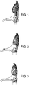
- the figure 1 represents a human skeleton of a person seated in an ergonomic posture that does not cause lower back pain.
- the figure 2 depicts a human skeleton of a person seated in a posture in which his pelvis is rotated backwards. This posture is unsuitable and can cause lower back pain.
- the picture 3 depicts a human skeleton of a person seated in a posture in which his thorax is rotated forward. This posture is also unsuitable and can cause lower back pain.
- the detection method according to the present disclosure is suitable for detecting the rotation of a part of the trunk of a person seated on a seat of the detection system 2.
- the trunk of a person comprises the thorax, the abdomen and the pelvis also called pelvis.
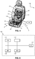
- the detection system 2 comprises a seat 4 of a vehicle, five interdigital capacitive sensors C1, C2, C3, C4, C5 carried by the seat, and a controller 100 electrically connected to the interdigital capacitive sensors.
- the vehicle can for example be a motor vehicle, a train, an airplane or a boat.
- the seat 4 comprises a seat 18 and a backrest 20 hinged to the seat around an axis extending in a transverse direction T.
- the seat 18 comprises a receiving face 22 intended to accommodate a person or an object.
- the receiving face of the seat is shared by a transverse central plane XX in a zone adjacent to the backrest, called the "rear part” 24, and in a zone located on the side opposite the backrest. , known as the “front part” 26.
- the backrest 20 also includes a receiving face 28 capable of receiving the back of a human person.
- the backrest extending in a longitudinal direction L and in a transverse direction T.
- the backrest, and in particular the receiving face 28 of the backrest carries three interdigital capacitive sensors of the detection system.
- the figure 4 shows an advantageous example of positioning interdigital capacitive sensors. This positioning was chosen taking into account the support zones of a human person seated on the seat.
- An interdigital capacitive sensor C1 is located on a lower and side area of the backrest.
- the interdigital capacitive sensor C1 is located at a location on the receiving face of the backrest which corresponds to a support zone for the gluteus maxims of this person.
- An interdigital capacitive sensor C2 is arranged on an upper and lateral zone of the backrest. Thus, this interdigital capacitive sensor C2 is located at a location of the backrest which corresponds to a bearing zone of a scapula of the person seated on the seat and leaning against the backrest.
- An interdigital capacitive sensor C3 is located on a lower or central area in the longitudinal direction L, and central in the transverse direction T. This interdigital capacitive sensor C3 is located at a location of the backrest which corresponds to a support area of the lumbar vertebrae of this person.
- the interdigital capacitive sensor C3 is located vertically between the interdigital capacitive sensor C2 and the interdigital capacitive sensor C1.
- the interdigital capacitive sensor C3 is always located below the interdigital sensor C2.
- the seat carries two interdigital capacitive sensors of the detection system.
- An interdigital capacitive sensor C4 is located on a side zone of the rear part 24 of the seat.
- the interdigital capacitive sensor C4 is located at a location on the receiving face of the seat which corresponds to a support zone for a buttock of the person seated on the seat and leaning against the backrest.
- an interdigital capacitive sensor C5 is located on a side zone of the front part 26 of the seat.
- the interdigital capacitive sensor C5 is located at a location of the seat which corresponds to a support zone of a hamstring of this person.
- the controller 100 of the determination system comprises a communication bus connected, for example, to a central processing unit 101, such as a processor or a microprocessor, and denoted CPU.
- the controller 100 also comprises a memory 102 and an executable code making it possible to implement implements the detection method by means of the seat and the interdigital capacitive sensors previously described.
- the controller 100 can be a programmable device that uses software, a specific integrated circuit (ASIC) or part of an engine control unit (ECU).
- the controller 100 may optionally include a network interface 104 which is normally connected to a communication network over which digital data to be processed is transmitted or received; a user interface 105 for receiving inputs from a user or for displaying information to a user, an input-output module 107, denoted IO, for receiving, sending data from or to external peripherals such as hard disk, removable storage medium or others.
- the memory 102 comprises ranges of variation of capacitive values defined for sets of capacitive sensors and allowing detection of the rotation of part of the trunk of an occupant seated on a seat
- an assembly comprises the capacitive sensor C3 associated with a first range of variation greater than 7500 pico Farads and the capacitive sensor C4 associated with a first range of variation greater than 6000 pico Farads.
- This set of capacitive sensors C3, C4 and these first ranges of variation allow the detection of a rotation of the pelvis of the occupant as illustrated on the picture 2 and as explained later in the description of the process.
- Another assembly comprises the capacitive sensor C1 associated with a second range of variation greater than 4500 pico Farads or between -3000 pico Farads and +3000 pico Farads, the capacitive sensor C3 associated with a second range of variation greater than 7500 pico Farads and the capacitive sensor C4 associated with a second range of variation greater than 4500 pico Farads.
- This set of capacitive sensors C1, C3, C4 and these second ranges of variation also allow the detection of rotation of the occupant's pelvis.
- the table below shows the capacitive sensors and the ranges of variation of capacitive values allowing detection of backward rotation of the pelvis.
- an assembly comprises the capacitive sensor C1 associated with a variation range greater than 7500 pico Farads, the capacitive sensor C2 associated with a variation range greater than 12000 pico Farads, the capacitive sensor C4 associated with a variation range less than - 3500 pico Farads, the capacitive sensor C5 associated with a range of variation less than 3000 pico Farads.
- This set of capacitive sensors C1, C2, C4 and C5 and these ranges of variation allow the detection of a rotation of the pelvis of the occupant as illustrated on the picture 3 and as explained later in the description of the method.
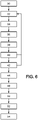
- the method for detecting a rotation of at least part of the trunk of an occupant seated on a seat begins with a step 30 of triggering a phase of measurement of capacitive values by the capacitive sensors C1 to C5.
- the measurement phase lasts for the entire duration of the detection process.
- the measurement phase includes measurement periods.
- the capacitive sensors C1 to C5 measure several capacitive values.
- the method comprises steps of processing the capacitive values measured in each measurement period in order to determine a first stationary posture of the occupant seated on the seat, a modification of the position of the occupant to put himself in a position which can lead to a pain in his back, and a new still position called second stationary posture.
- an average value is calculated from the capacitive values measured for each capacitive sensor, during a period called the previous period.
- a minimum threshold and a maximum threshold are calculated for each capacitive sensor.
- the minimum threshold is calculated by subtracting 3000 pico Farads from the average value calculated for each capacitive sensor during step 32.
- a maximum threshold is calculated by adding 3000 pico Farads to the average value calculated for each capacitive sensor during of step 32.
- the capacitive values measured during one or more subsequent periods are compared with the minimum threshold and with the maximum threshold, for each capacitive sensor.
- a first stationary posture is determined during of a step 38.
- This stationary posture corresponds to immobility of the trunk and the hamstrings of the occupant seated on the seat.
- the period during which the first stationary posture is determined is referred to as the first stationary period in this patent application.
- the measurement phase of the capacitive values continues in order to determine whether the occupant of the seat modifies his position to put himself in a position that could cause pain in his back. Processing steps 32-36 are repeated until occupant trunk motion is determined in step 40. Occupant trunk motion is determined when the capacitive values measured during of one or more following periods are higher or lower than 4000 pico Farads for a duration of at least 3 seconds. The movement of the occupant's trunk is a rotational movement around an axis parallel to the transverse axis T.
- steps 32 to 36 are repeated until a second stationary posture of the occupant is determined during a step 42.
- the period during which the second stationary posture is determined is called the second stationary period. in this patent application.
- a value representative of the capacitive values measured during the first stationary period is determined for each capacitive sensor.
- a value representative of the capacitive values measured during the second stationary period is also determined for each capacitive sensor. These representative values are for example the average values of the capacitive values measured during each stationary period.
- the detection signal is generated during a step 50, only if the capacitive values measured during the second stationary period are between the maximum threshold and the minimum threshold for a duration of at least ten seconds.
- the variation between the mean of the capacitive values measured during the first stationary period, and the mean value of the capacitive values measured during the second stationary period, is calculated for the capacitive sensors C1, C3 and C4.
- the variations calculated for the capacitive sensors C1, C3 and C4 are compared with the first and second ranges of capacitive values recorded in the memory 102 and indicated in table 1.
- step 46 the variation between the mean of the capacitive values measured during the first stationary period, and the mean value of the capacitive values measured during the second stationary period, is calculated for capacitive sensors C1, C2, C4 and C5.
- step 48 the variations calculated for the capacitive sensors C1, C2, C4 and C5 are compared with the ranges of capacitive values recorded in the memory 102 and indicated in table 2.
- the signal for detecting a rotation of the thorax is generated during step 52, only if the capacitive values measured during the second stationary period are between the minimum threshold and the maximum threshold for a duration d at least three seconds.
- the detection method may also include a step 54 of warning the occupant of the seat by the triggering of a sound, a display or the generation of a vibration.
- the method further comprises a step of transmitting a generated detection signal to a device for managing the triggering of an airbag.
- This signal is used by the latter to manage the triggering of the airbag depending on the position of the occupant.
- the detection signal generated is representative of at least one position of the occupant from among a rotation of a part of the trunk of the occupant, a rotation of the thorax of the occupant and a rotation of the pelvis of the occupant.
- the airbag triggering management device uses this information to trigger the airbag or not or to decide on the force of this triggering.
Landscapes
- Engineering & Computer Science (AREA)
- Mechanical Engineering (AREA)
- Aviation & Aerospace Engineering (AREA)
- Transportation (AREA)
- Human Computer Interaction (AREA)
- Seats For Vehicles (AREA)
- Air Bags (AREA)
Applications Claiming Priority (1)
| Application Number | Priority Date | Filing Date | Title |
|---|---|---|---|
| FR2101745A FR3120124B1 (fr) | 2021-02-23 | 2021-02-23 | Procédé de détection d’une rotation d’une partie du tronc d’un occupant assis sur un siège |
Publications (2)
| Publication Number | Publication Date |
|---|---|
| EP4046863A1 true EP4046863A1 (de) | 2022-08-24 |
| EP4046863B1 EP4046863B1 (de) | 2024-05-15 |
Family
ID=75539547
Family Applications (1)
| Application Number | Title | Priority Date | Filing Date |
|---|---|---|---|
| EP22156636.7A Active EP4046863B1 (de) | 2021-02-23 | 2022-02-14 | Verfahren zum erkennen einer drehung eines teils des rumpfes eines insassen, der auf einem sitz sitzt |
Country Status (4)
| Country | Link |
|---|---|
| US (1) | US20220266724A1 (de) |
| EP (1) | EP4046863B1 (de) |
| CN (1) | CN114954147A (de) |
| FR (1) | FR3120124B1 (de) |
Families Citing this family (6)
| Publication number | Priority date | Publication date | Assignee | Title |
|---|---|---|---|---|
| FR3140819B1 (fr) | 2022-10-12 | 2024-10-04 | Faurecia Sieges Dautomobile | Tapis de détection d’occupation d’un siège de véhicule automobile, système de détermination d’une capacité, procédé de détermination d’une capacité ou d’un état d’occupation d’un siège, procédé de détection d’une rotation d’une partie du tronc d’un occupant assis sur un siège |
| DE102023114316A1 (de) | 2023-05-31 | 2024-12-05 | Faurecia Autositze Gmbh | Abnehmbare Sitzabdeckung und Verfahren zur Steuerung dieser Abdeckung |
| FR3153582B1 (fr) | 2023-09-29 | 2025-12-19 | Faurecia Sieges Dautomobile | Procédé et système d’assistance à la conduite d’un véhicule |
| FR3154662A1 (fr) | 2023-10-31 | 2025-05-02 | Faurecia Sièges d'Automobile | Elément de siège et siège, notamment de véhicule automobile |
| FR3154664B1 (fr) | 2023-10-31 | 2025-11-07 | Faurecia Sieges Dautomobile | Elément de siège et siège, notamment de véhicule automobile |
| FR3158072B1 (fr) * | 2024-01-05 | 2026-01-02 | Faurecia Sieges Dautomobile | Procédé de détection d’une posture inappropriée d’un occupant assis sur un siège d’un véhicule |
Citations (2)
| Publication number | Priority date | Publication date | Assignee | Title |
|---|---|---|---|---|
| EP1129893A2 (de) * | 2000-03-03 | 2001-09-05 | Bayerische Motoren Werke Aktiengesellschaft | Verfahren zur kapazitiven Objekterkennung bei Fahrzeugen |
| DE102008044903A1 (de) * | 2008-08-29 | 2010-03-04 | Continental Automotive Gmbh | Erkennung einer Positionsveränderung von Fahrzeuginsassen |
Family Cites Families (4)
| Publication number | Priority date | Publication date | Assignee | Title |
|---|---|---|---|---|
| US8174508B2 (en) * | 2007-11-19 | 2012-05-08 | Microsoft Corporation | Pointing and data entry input device |
| US8175774B2 (en) * | 2008-05-16 | 2012-05-08 | Infineon Technologies Ag | Capacitive object recognition using adjustable electrode |
| US9987962B1 (en) * | 2017-03-09 | 2018-06-05 | Ford Global Technologies, Llc | Vehicle haptic feedback as a function of sensed capacitance |
| US11254238B2 (en) * | 2019-09-16 | 2022-02-22 | Ford Global Technologies, Llc | Occupant position detection with active electric field sensor |
-
2021
- 2021-02-23 FR FR2101745A patent/FR3120124B1/fr active Active
-
2022
- 2022-02-14 EP EP22156636.7A patent/EP4046863B1/de active Active
- 2022-02-21 CN CN202210155781.6A patent/CN114954147A/zh active Pending
- 2022-02-22 US US17/677,211 patent/US20220266724A1/en active Pending
Patent Citations (2)
| Publication number | Priority date | Publication date | Assignee | Title |
|---|---|---|---|---|
| EP1129893A2 (de) * | 2000-03-03 | 2001-09-05 | Bayerische Motoren Werke Aktiengesellschaft | Verfahren zur kapazitiven Objekterkennung bei Fahrzeugen |
| DE102008044903A1 (de) * | 2008-08-29 | 2010-03-04 | Continental Automotive Gmbh | Erkennung einer Positionsveränderung von Fahrzeuginsassen |
Also Published As
| Publication number | Publication date |
|---|---|
| EP4046863B1 (de) | 2024-05-15 |
| CN114954147A (zh) | 2022-08-30 |
| US20220266724A1 (en) | 2022-08-25 |
| FR3120124A1 (fr) | 2022-08-26 |
| FR3120124B1 (fr) | 2023-10-20 |
Similar Documents
| Publication | Publication Date | Title |
|---|---|---|
| EP4046863B1 (de) | Verfahren zum erkennen einer drehung eines teils des rumpfes eines insassen, der auf einem sitz sitzt | |
| EP1250084B1 (de) | System zur fernüberwachung von patienten | |
| EP4006515B1 (de) | Verfahren zur bestimmung des besetzungszustands eines sitzes und entsprechendes bestimmungssystem | |
| EP1438922B1 (de) | Vorrichtung und Verfahren zur Schätzung der Hydrierung von Haut und Schleimhaut | |
| FR3106094A1 (fr) | Siege de vehicule avec systeme de surveillance | |
| FR3098769A1 (fr) | Siege de vehicule avec systeme de compensation | |
| FR3099610A1 (fr) | Dispositif d’evaluation d’emotion | |
| EP3424030A1 (de) | Personalisierte vorrichtung und verfahren zur überwachung eines kraftfahrzeugfahrers | |
| EP1800602A1 (de) | Fahrerbewegungsbasierte Kraftfahrzeugsfahrer-Aufmerksamkeitsüberwachung | |
| EP1177766A1 (de) | Verfahren zur Erfassung von nicht-dermatoglyphischem Hautbereich oder Haarbereich mittels einer Erfassungsvorrichtung mit einem nicht-optischen Detektor | |
| EP3153145A1 (de) | Lehnsessel für medizindiagnostik | |
| FR3113760A1 (fr) | Dispositif électronique et procédé de réduction de diaphonie, système audio pour appuis-têtes de sièges et programme d’ordinateur associés | |
| FR2870378A1 (fr) | Protection de detection de chutes a domicile, notamment de personnes a autonomie restreinte | |
| FR3148296A1 (fr) | Procédé de détection d’occupation d’un siège d’un véhicule et procédé de détection d’un tassement définitif de la mousse d’un siège | |
| FR3158072A1 (fr) | Procédé de détection d’une posture inappropriée d’un occupant assis sur un siège d’un véhicule | |
| FR3141400A1 (fr) | Système d’aide à la posture dans un siège de véhicule | |
| FR3119131A1 (fr) | Système et procédé d’estimation de la taille d’un usager d’un siège et un procédé de fabrication d’un tel système | |
| FR3079652A1 (fr) | Procede d'evaluation d'une distance, systeme d'evaluation associe et systeme de gestion d'un coussin gonflable | |
| WO2025247793A1 (fr) | Procédé de détermination d'un type staturo-pondéral d'un occupant d'un siège et siège associé | |
| FR3119804A1 (fr) | Système de siège avec entrée facile au troisième rang | |
| FR3156081A1 (fr) | Procédé de détection d’une position d’un siège enfant et système de détection associé | |
| FR3023955A1 (fr) | Systeme et procede d'assistance pour detecter et signaler un etat de risque chez un utilisateur | |
| FR3153582A1 (fr) | Procédé et système d’assistance à la conduite d’un véhicule | |
| EP4402648B1 (de) | Procédé de détection d'un mouvement d'un corps | |
| FR3123269A1 (fr) | Activation ciblée d’un dispositif d’amélioration du confort d’assise d’un siège de véhicule |
Legal Events
| Date | Code | Title | Description |
|---|---|---|---|
| PUAI | Public reference made under article 153(3) epc to a published international application that has entered the european phase |
Free format text: ORIGINAL CODE: 0009012 |
|
| STAA | Information on the status of an ep patent application or granted ep patent |
Free format text: STATUS: THE APPLICATION HAS BEEN PUBLISHED |
|
| AK | Designated contracting states |
Kind code of ref document: A1 Designated state(s): AL AT BE BG CH CY CZ DE DK EE ES FI FR GB GR HR HU IE IS IT LI LT LU LV MC MK MT NL NO PL PT RO RS SE SI SK SM TR |
|
| STAA | Information on the status of an ep patent application or granted ep patent |
Free format text: STATUS: REQUEST FOR EXAMINATION WAS MADE |
|
| 17P | Request for examination filed |
Effective date: 20221214 |
|
| RBV | Designated contracting states (corrected) |
Designated state(s): AL AT BE BG CH CY CZ DE DK EE ES FI FR GB GR HR HU IE IS IT LI LT LU LV MC MK MT NL NO PL PT RO RS SE SI SK SM TR |
|
| GRAP | Despatch of communication of intention to grant a patent |
Free format text: ORIGINAL CODE: EPIDOSNIGR1 |
|
| STAA | Information on the status of an ep patent application or granted ep patent |
Free format text: STATUS: GRANT OF PATENT IS INTENDED |
|
| INTG | Intention to grant announced |
Effective date: 20231212 |
|
| GRAS | Grant fee paid |
Free format text: ORIGINAL CODE: EPIDOSNIGR3 |
|
| GRAA | (expected) grant |
Free format text: ORIGINAL CODE: 0009210 |
|
| STAA | Information on the status of an ep patent application or granted ep patent |
Free format text: STATUS: THE PATENT HAS BEEN GRANTED |
|
| AK | Designated contracting states |
Kind code of ref document: B1 Designated state(s): AL AT BE BG CH CY CZ DE DK EE ES FI FR GB GR HR HU IE IS IT LI LT LU LV MC MK MT NL NO PL PT RO RS SE SI SK SM TR |
|
| REG | Reference to a national code |
Ref country code: CH Ref legal event code: EP |
|
| REG | Reference to a national code |
Ref country code: DE Ref legal event code: R096 Ref document number: 602022003403 Country of ref document: DE |
|
| REG | Reference to a national code |
Ref country code: IE Ref legal event code: FG4D Free format text: LANGUAGE OF EP DOCUMENT: FRENCH |
|
| REG | Reference to a national code |
Ref country code: SE Ref legal event code: TRGR |
|
| REG | Reference to a national code |
Ref country code: LT Ref legal event code: MG9D |
|
| REG | Reference to a national code |
Ref country code: NL Ref legal event code: MP Effective date: 20240515 |
|
| PG25 | Lapsed in a contracting state [announced via postgrant information from national office to epo] |
Ref country code: IS Free format text: LAPSE BECAUSE OF FAILURE TO SUBMIT A TRANSLATION OF THE DESCRIPTION OR TO PAY THE FEE WITHIN THE PRESCRIBED TIME-LIMIT Effective date: 20240915 |
|
| PG25 | Lapsed in a contracting state [announced via postgrant information from national office to epo] |
Ref country code: BG Free format text: LAPSE BECAUSE OF FAILURE TO SUBMIT A TRANSLATION OF THE DESCRIPTION OR TO PAY THE FEE WITHIN THE PRESCRIBED TIME-LIMIT Effective date: 20240515 |
|
| PG25 | Lapsed in a contracting state [announced via postgrant information from national office to epo] |
Ref country code: HR Free format text: LAPSE BECAUSE OF FAILURE TO SUBMIT A TRANSLATION OF THE DESCRIPTION OR TO PAY THE FEE WITHIN THE PRESCRIBED TIME-LIMIT Effective date: 20240515 Ref country code: FI Free format text: LAPSE BECAUSE OF FAILURE TO SUBMIT A TRANSLATION OF THE DESCRIPTION OR TO PAY THE FEE WITHIN THE PRESCRIBED TIME-LIMIT Effective date: 20240515 |
|
| PG25 | Lapsed in a contracting state [announced via postgrant information from national office to epo] |
Ref country code: GR Free format text: LAPSE BECAUSE OF FAILURE TO SUBMIT A TRANSLATION OF THE DESCRIPTION OR TO PAY THE FEE WITHIN THE PRESCRIBED TIME-LIMIT Effective date: 20240816 |
|
| PG25 | Lapsed in a contracting state [announced via postgrant information from national office to epo] |
Ref country code: PT Free format text: LAPSE BECAUSE OF FAILURE TO SUBMIT A TRANSLATION OF THE DESCRIPTION OR TO PAY THE FEE WITHIN THE PRESCRIBED TIME-LIMIT Effective date: 20240916 |
|
| REG | Reference to a national code |
Ref country code: AT Ref legal event code: MK05 Ref document number: 1686690 Country of ref document: AT Kind code of ref document: T Effective date: 20240515 |
|
| PG25 | Lapsed in a contracting state [announced via postgrant information from national office to epo] |
Ref country code: NL Free format text: LAPSE BECAUSE OF FAILURE TO SUBMIT A TRANSLATION OF THE DESCRIPTION OR TO PAY THE FEE WITHIN THE PRESCRIBED TIME-LIMIT Effective date: 20240515 |
|
| PG25 | Lapsed in a contracting state [announced via postgrant information from national office to epo] |
Ref country code: ES Free format text: LAPSE BECAUSE OF FAILURE TO SUBMIT A TRANSLATION OF THE DESCRIPTION OR TO PAY THE FEE WITHIN THE PRESCRIBED TIME-LIMIT Effective date: 20240515 |
|
| PG25 | Lapsed in a contracting state [announced via postgrant information from national office to epo] |
Ref country code: AT Free format text: LAPSE BECAUSE OF FAILURE TO SUBMIT A TRANSLATION OF THE DESCRIPTION OR TO PAY THE FEE WITHIN THE PRESCRIBED TIME-LIMIT Effective date: 20240515 |
|
| PG25 | Lapsed in a contracting state [announced via postgrant information from national office to epo] |
Ref country code: PL Free format text: LAPSE BECAUSE OF FAILURE TO SUBMIT A TRANSLATION OF THE DESCRIPTION OR TO PAY THE FEE WITHIN THE PRESCRIBED TIME-LIMIT Effective date: 20240515 |
|
| PG25 | Lapsed in a contracting state [announced via postgrant information from national office to epo] |
Ref country code: LV Free format text: LAPSE BECAUSE OF FAILURE TO SUBMIT A TRANSLATION OF THE DESCRIPTION OR TO PAY THE FEE WITHIN THE PRESCRIBED TIME-LIMIT Effective date: 20240515 |
|
| PG25 | Lapsed in a contracting state [announced via postgrant information from national office to epo] |
Ref country code: PT Free format text: LAPSE BECAUSE OF FAILURE TO SUBMIT A TRANSLATION OF THE DESCRIPTION OR TO PAY THE FEE WITHIN THE PRESCRIBED TIME-LIMIT Effective date: 20240916 Ref country code: PL Free format text: LAPSE BECAUSE OF FAILURE TO SUBMIT A TRANSLATION OF THE DESCRIPTION OR TO PAY THE FEE WITHIN THE PRESCRIBED TIME-LIMIT Effective date: 20240515 Ref country code: NO Free format text: LAPSE BECAUSE OF FAILURE TO SUBMIT A TRANSLATION OF THE DESCRIPTION OR TO PAY THE FEE WITHIN THE PRESCRIBED TIME-LIMIT Effective date: 20240815 Ref country code: NL Free format text: LAPSE BECAUSE OF FAILURE TO SUBMIT A TRANSLATION OF THE DESCRIPTION OR TO PAY THE FEE WITHIN THE PRESCRIBED TIME-LIMIT Effective date: 20240515 Ref country code: LV Free format text: LAPSE BECAUSE OF FAILURE TO SUBMIT A TRANSLATION OF THE DESCRIPTION OR TO PAY THE FEE WITHIN THE PRESCRIBED TIME-LIMIT Effective date: 20240515 Ref country code: IS Free format text: LAPSE BECAUSE OF FAILURE TO SUBMIT A TRANSLATION OF THE DESCRIPTION OR TO PAY THE FEE WITHIN THE PRESCRIBED TIME-LIMIT Effective date: 20240915 Ref country code: HR Free format text: LAPSE BECAUSE OF FAILURE TO SUBMIT A TRANSLATION OF THE DESCRIPTION OR TO PAY THE FEE WITHIN THE PRESCRIBED TIME-LIMIT Effective date: 20240515 Ref country code: GR Free format text: LAPSE BECAUSE OF FAILURE TO SUBMIT A TRANSLATION OF THE DESCRIPTION OR TO PAY THE FEE WITHIN THE PRESCRIBED TIME-LIMIT Effective date: 20240816 Ref country code: FI Free format text: LAPSE BECAUSE OF FAILURE TO SUBMIT A TRANSLATION OF THE DESCRIPTION OR TO PAY THE FEE WITHIN THE PRESCRIBED TIME-LIMIT Effective date: 20240515 Ref country code: ES Free format text: LAPSE BECAUSE OF FAILURE TO SUBMIT A TRANSLATION OF THE DESCRIPTION OR TO PAY THE FEE WITHIN THE PRESCRIBED TIME-LIMIT Effective date: 20240515 Ref country code: BG Free format text: LAPSE BECAUSE OF FAILURE TO SUBMIT A TRANSLATION OF THE DESCRIPTION OR TO PAY THE FEE WITHIN THE PRESCRIBED TIME-LIMIT Effective date: 20240515 Ref country code: AT Free format text: LAPSE BECAUSE OF FAILURE TO SUBMIT A TRANSLATION OF THE DESCRIPTION OR TO PAY THE FEE WITHIN THE PRESCRIBED TIME-LIMIT Effective date: 20240515 Ref country code: RS Free format text: LAPSE BECAUSE OF FAILURE TO SUBMIT A TRANSLATION OF THE DESCRIPTION OR TO PAY THE FEE WITHIN THE PRESCRIBED TIME-LIMIT Effective date: 20240815 |
|
| PG25 | Lapsed in a contracting state [announced via postgrant information from national office to epo] |
Ref country code: DK Free format text: LAPSE BECAUSE OF FAILURE TO SUBMIT A TRANSLATION OF THE DESCRIPTION OR TO PAY THE FEE WITHIN THE PRESCRIBED TIME-LIMIT Effective date: 20240515 |
|
| PG25 | Lapsed in a contracting state [announced via postgrant information from national office to epo] |
Ref country code: EE Free format text: LAPSE BECAUSE OF FAILURE TO SUBMIT A TRANSLATION OF THE DESCRIPTION OR TO PAY THE FEE WITHIN THE PRESCRIBED TIME-LIMIT Effective date: 20240515 |
|
| PG25 | Lapsed in a contracting state [announced via postgrant information from national office to epo] |
Ref country code: CZ Free format text: LAPSE BECAUSE OF FAILURE TO SUBMIT A TRANSLATION OF THE DESCRIPTION OR TO PAY THE FEE WITHIN THE PRESCRIBED TIME-LIMIT Effective date: 20240515 |
|
| PG25 | Lapsed in a contracting state [announced via postgrant information from national office to epo] |
Ref country code: SK Free format text: LAPSE BECAUSE OF FAILURE TO SUBMIT A TRANSLATION OF THE DESCRIPTION OR TO PAY THE FEE WITHIN THE PRESCRIBED TIME-LIMIT Effective date: 20240515 Ref country code: RO Free format text: LAPSE BECAUSE OF FAILURE TO SUBMIT A TRANSLATION OF THE DESCRIPTION OR TO PAY THE FEE WITHIN THE PRESCRIBED TIME-LIMIT Effective date: 20240515 |
|
| PG25 | Lapsed in a contracting state [announced via postgrant information from national office to epo] |
Ref country code: SM Free format text: LAPSE BECAUSE OF FAILURE TO SUBMIT A TRANSLATION OF THE DESCRIPTION OR TO PAY THE FEE WITHIN THE PRESCRIBED TIME-LIMIT Effective date: 20240515 |
|
| PG25 | Lapsed in a contracting state [announced via postgrant information from national office to epo] |
Ref country code: SM Free format text: LAPSE BECAUSE OF FAILURE TO SUBMIT A TRANSLATION OF THE DESCRIPTION OR TO PAY THE FEE WITHIN THE PRESCRIBED TIME-LIMIT Effective date: 20240515 Ref country code: SK Free format text: LAPSE BECAUSE OF FAILURE TO SUBMIT A TRANSLATION OF THE DESCRIPTION OR TO PAY THE FEE WITHIN THE PRESCRIBED TIME-LIMIT Effective date: 20240515 Ref country code: RO Free format text: LAPSE BECAUSE OF FAILURE TO SUBMIT A TRANSLATION OF THE DESCRIPTION OR TO PAY THE FEE WITHIN THE PRESCRIBED TIME-LIMIT Effective date: 20240515 Ref country code: EE Free format text: LAPSE BECAUSE OF FAILURE TO SUBMIT A TRANSLATION OF THE DESCRIPTION OR TO PAY THE FEE WITHIN THE PRESCRIBED TIME-LIMIT Effective date: 20240515 Ref country code: DK Free format text: LAPSE BECAUSE OF FAILURE TO SUBMIT A TRANSLATION OF THE DESCRIPTION OR TO PAY THE FEE WITHIN THE PRESCRIBED TIME-LIMIT Effective date: 20240515 Ref country code: CZ Free format text: LAPSE BECAUSE OF FAILURE TO SUBMIT A TRANSLATION OF THE DESCRIPTION OR TO PAY THE FEE WITHIN THE PRESCRIBED TIME-LIMIT Effective date: 20240515 |
|
| PG25 | Lapsed in a contracting state [announced via postgrant information from national office to epo] |
Ref country code: IT Free format text: LAPSE BECAUSE OF FAILURE TO SUBMIT A TRANSLATION OF THE DESCRIPTION OR TO PAY THE FEE WITHIN THE PRESCRIBED TIME-LIMIT Effective date: 20240515 |
|
| REG | Reference to a national code |
Ref country code: DE Ref legal event code: R082 Ref document number: 602022003403 Country of ref document: DE Representative=s name: PLASSERAUD IP GMBH, DE |
|
| REG | Reference to a national code |
Ref country code: DE Ref legal event code: R097 Ref document number: 602022003403 Country of ref document: DE |
|
| PLBE | No opposition filed within time limit |
Free format text: ORIGINAL CODE: 0009261 |
|
| STAA | Information on the status of an ep patent application or granted ep patent |
Free format text: STATUS: NO OPPOSITION FILED WITHIN TIME LIMIT |
|
| 26N | No opposition filed |
Effective date: 20250218 |
|
| PG25 | Lapsed in a contracting state [announced via postgrant information from national office to epo] |
Ref country code: SI Free format text: LAPSE BECAUSE OF FAILURE TO SUBMIT A TRANSLATION OF THE DESCRIPTION OR TO PAY THE FEE WITHIN THE PRESCRIBED TIME-LIMIT Effective date: 20240515 |
|
| PG25 | Lapsed in a contracting state [announced via postgrant information from national office to epo] |
Ref country code: MC Free format text: LAPSE BECAUSE OF FAILURE TO SUBMIT A TRANSLATION OF THE DESCRIPTION OR TO PAY THE FEE WITHIN THE PRESCRIBED TIME-LIMIT Effective date: 20240515 |
|
| REG | Reference to a national code |
Ref country code: CH Ref legal event code: PL |
|
| PG25 | Lapsed in a contracting state [announced via postgrant information from national office to epo] |
Ref country code: LU Free format text: LAPSE BECAUSE OF NON-PAYMENT OF DUE FEES Effective date: 20250214 |
|
| PG25 | Lapsed in a contracting state [announced via postgrant information from national office to epo] |
Ref country code: CH Free format text: LAPSE BECAUSE OF NON-PAYMENT OF DUE FEES Effective date: 20250228 |
|
| REG | Reference to a national code |
Ref country code: BE Ref legal event code: MM Effective date: 20250228 |
|
| PG25 | Lapsed in a contracting state [announced via postgrant information from national office to epo] |
Ref country code: BE Free format text: LAPSE BECAUSE OF NON-PAYMENT OF DUE FEES Effective date: 20250228 |
|
| PG25 | Lapsed in a contracting state [announced via postgrant information from national office to epo] |
Ref country code: IE Free format text: LAPSE BECAUSE OF NON-PAYMENT OF DUE FEES Effective date: 20250214 |
|
| PGFP | Annual fee paid to national office [announced via postgrant information from national office to epo] |
Ref country code: SE Payment date: 20260121 Year of fee payment: 5 |
|
| PGFP | Annual fee paid to national office [announced via postgrant information from national office to epo] |
Ref country code: GB Payment date: 20260122 Year of fee payment: 5 |
|
| PGFP | Annual fee paid to national office [announced via postgrant information from national office to epo] |
Ref country code: DE Payment date: 20260121 Year of fee payment: 5 |
|
| PGFP | Annual fee paid to national office [announced via postgrant information from national office to epo] |
Ref country code: FR Payment date: 20260121 Year of fee payment: 5 |