EP4046862B1 - Control method and apparatus, power system and electric vehicle - Google Patents
Control method and apparatus, power system and electric vehicle Download PDFInfo
- Publication number
- EP4046862B1 EP4046862B1 EP21766558.7A EP21766558A EP4046862B1 EP 4046862 B1 EP4046862 B1 EP 4046862B1 EP 21766558 A EP21766558 A EP 21766558A EP 4046862 B1 EP4046862 B1 EP 4046862B1
- Authority
- EP
- European Patent Office
- Prior art keywords
- power battery
- reference value
- control signal
- inverter
- axis component
- Prior art date
- Legal status (The legal status is an assumption and is not a legal conclusion. Google has not performed a legal analysis and makes no representation as to the accuracy of the status listed.)
- Active
Links
Images

Classifications
-
- H—ELECTRICITY
- H02—GENERATION; CONVERSION OR DISTRIBUTION OF ELECTRIC POWER
- H02P—CONTROL OR REGULATION OF ELECTRIC MOTORS, ELECTRIC GENERATORS OR DYNAMO-ELECTRIC CONVERTERS; CONTROLLING TRANSFORMERS, REACTORS OR CHOKE COILS
- H02P29/00—Arrangements for regulating or controlling electric motors, appropriate for both AC and DC motors
- H02P29/60—Controlling or determining the temperature of the motor or of the drive
-
- B—PERFORMING OPERATIONS; TRANSPORTING
- B60—VEHICLES IN GENERAL
- B60L—PROPULSION OF ELECTRICALLY-PROPELLED VEHICLES; SUPPLYING ELECTRIC POWER FOR AUXILIARY EQUIPMENT OF ELECTRICALLY-PROPELLED VEHICLES; ELECTRODYNAMIC BRAKE SYSTEMS FOR VEHICLES IN GENERAL; MAGNETIC SUSPENSION OR LEVITATION FOR VEHICLES; MONITORING OPERATING VARIABLES OF ELECTRICALLY-PROPELLED VEHICLES; ELECTRIC SAFETY DEVICES FOR ELECTRICALLY-PROPELLED VEHICLES
- B60L58/00—Methods or circuit arrangements for monitoring or controlling batteries or fuel cells, specially adapted for electric vehicles
- B60L58/10—Methods or circuit arrangements for monitoring or controlling batteries or fuel cells, specially adapted for electric vehicles for monitoring or controlling batteries
- B60L58/24—Methods or circuit arrangements for monitoring or controlling batteries or fuel cells, specially adapted for electric vehicles for monitoring or controlling batteries for controlling the temperature of batteries
-
- B—PERFORMING OPERATIONS; TRANSPORTING
- B60—VEHICLES IN GENERAL
- B60L—PROPULSION OF ELECTRICALLY-PROPELLED VEHICLES; SUPPLYING ELECTRIC POWER FOR AUXILIARY EQUIPMENT OF ELECTRICALLY-PROPELLED VEHICLES; ELECTRODYNAMIC BRAKE SYSTEMS FOR VEHICLES IN GENERAL; MAGNETIC SUSPENSION OR LEVITATION FOR VEHICLES; MONITORING OPERATING VARIABLES OF ELECTRICALLY-PROPELLED VEHICLES; ELECTRIC SAFETY DEVICES FOR ELECTRICALLY-PROPELLED VEHICLES
- B60L1/00—Supplying electric power to auxiliary equipment of vehicles
- B60L1/02—Supplying electric power to auxiliary equipment of vehicles to electric heating circuits
-
- B—PERFORMING OPERATIONS; TRANSPORTING
- B60—VEHICLES IN GENERAL
- B60L—PROPULSION OF ELECTRICALLY-PROPELLED VEHICLES; SUPPLYING ELECTRIC POWER FOR AUXILIARY EQUIPMENT OF ELECTRICALLY-PROPELLED VEHICLES; ELECTRODYNAMIC BRAKE SYSTEMS FOR VEHICLES IN GENERAL; MAGNETIC SUSPENSION OR LEVITATION FOR VEHICLES; MONITORING OPERATING VARIABLES OF ELECTRICALLY-PROPELLED VEHICLES; ELECTRIC SAFETY DEVICES FOR ELECTRICALLY-PROPELLED VEHICLES
- B60L50/00—Electric propulsion with power supplied within the vehicle
- B60L50/50—Electric propulsion with power supplied within the vehicle using propulsion power supplied by batteries or fuel cells
- B60L50/51—Electric propulsion with power supplied within the vehicle using propulsion power supplied by batteries or fuel cells characterised by AC-motors
-
- B—PERFORMING OPERATIONS; TRANSPORTING
- B60—VEHICLES IN GENERAL
- B60L—PROPULSION OF ELECTRICALLY-PROPELLED VEHICLES; SUPPLYING ELECTRIC POWER FOR AUXILIARY EQUIPMENT OF ELECTRICALLY-PROPELLED VEHICLES; ELECTRODYNAMIC BRAKE SYSTEMS FOR VEHICLES IN GENERAL; MAGNETIC SUSPENSION OR LEVITATION FOR VEHICLES; MONITORING OPERATING VARIABLES OF ELECTRICALLY-PROPELLED VEHICLES; ELECTRIC SAFETY DEVICES FOR ELECTRICALLY-PROPELLED VEHICLES
- B60L58/00—Methods or circuit arrangements for monitoring or controlling batteries or fuel cells, specially adapted for electric vehicles
- B60L58/10—Methods or circuit arrangements for monitoring or controlling batteries or fuel cells, specially adapted for electric vehicles for monitoring or controlling batteries
- B60L58/24—Methods or circuit arrangements for monitoring or controlling batteries or fuel cells, specially adapted for electric vehicles for monitoring or controlling batteries for controlling the temperature of batteries
- B60L58/27—Methods or circuit arrangements for monitoring or controlling batteries or fuel cells, specially adapted for electric vehicles for monitoring or controlling batteries for controlling the temperature of batteries by heating
-
- H—ELECTRICITY
- H02—GENERATION; CONVERSION OR DISTRIBUTION OF ELECTRIC POWER
- H02P—CONTROL OR REGULATION OF ELECTRIC MOTORS, ELECTRIC GENERATORS OR DYNAMO-ELECTRIC CONVERTERS; CONTROLLING TRANSFORMERS, REACTORS OR CHOKE COILS
- H02P21/00—Arrangements or methods for the control of electric machines by vector control, e.g. by control of field orientation
- H02P21/22—Current control, e.g. using a current control loop
-
- H—ELECTRICITY
- H02—GENERATION; CONVERSION OR DISTRIBUTION OF ELECTRIC POWER
- H02P—CONTROL OR REGULATION OF ELECTRIC MOTORS, ELECTRIC GENERATORS OR DYNAMO-ELECTRIC CONVERTERS; CONTROLLING TRANSFORMERS, REACTORS OR CHOKE COILS
- H02P21/00—Arrangements or methods for the control of electric machines by vector control, e.g. by control of field orientation
- H02P21/50—Vector control arrangements or methods not otherwise provided for in H02P21/00- H02P21/36
-
- H—ELECTRICITY
- H02—GENERATION; CONVERSION OR DISTRIBUTION OF ELECTRIC POWER
- H02P—CONTROL OR REGULATION OF ELECTRIC MOTORS, ELECTRIC GENERATORS OR DYNAMO-ELECTRIC CONVERTERS; CONTROLLING TRANSFORMERS, REACTORS OR CHOKE COILS
- H02P27/00—Arrangements or methods for the control of AC motors characterised by the kind of supply voltage
- H02P27/04—Arrangements or methods for the control of AC motors characterised by the kind of supply voltage using variable-frequency supply voltage, e.g. inverter or converter supply voltage
- H02P27/06—Arrangements or methods for the control of AC motors characterised by the kind of supply voltage using variable-frequency supply voltage, e.g. inverter or converter supply voltage using DC to AC converters or inverters
- H02P27/08—Arrangements or methods for the control of AC motors characterised by the kind of supply voltage using variable-frequency supply voltage, e.g. inverter or converter supply voltage using DC to AC converters or inverters with pulse width modulation
- H02P27/085—Arrangements or methods for the control of AC motors characterised by the kind of supply voltage using variable-frequency supply voltage, e.g. inverter or converter supply voltage using DC to AC converters or inverters with pulse width modulation wherein the PWM mode is adapted on the running conditions of the motor, e.g. the switching frequency
-
- H—ELECTRICITY
- H02—GENERATION; CONVERSION OR DISTRIBUTION OF ELECTRIC POWER
- H02P—CONTROL OR REGULATION OF ELECTRIC MOTORS, ELECTRIC GENERATORS OR DYNAMO-ELECTRIC CONVERTERS; CONTROLLING TRANSFORMERS, REACTORS OR CHOKE COILS
- H02P29/00—Arrangements for regulating or controlling electric motors, appropriate for both AC and DC motors
- H02P29/60—Controlling or determining the temperature of the motor or of the drive
- H02P29/68—Controlling or determining the temperature of the motor or of the drive based on the temperature of a drive component or a semiconductor component
-
- B—PERFORMING OPERATIONS; TRANSPORTING
- B60—VEHICLES IN GENERAL
- B60L—PROPULSION OF ELECTRICALLY-PROPELLED VEHICLES; SUPPLYING ELECTRIC POWER FOR AUXILIARY EQUIPMENT OF ELECTRICALLY-PROPELLED VEHICLES; ELECTRODYNAMIC BRAKE SYSTEMS FOR VEHICLES IN GENERAL; MAGNETIC SUSPENSION OR LEVITATION FOR VEHICLES; MONITORING OPERATING VARIABLES OF ELECTRICALLY-PROPELLED VEHICLES; ELECTRIC SAFETY DEVICES FOR ELECTRICALLY-PROPELLED VEHICLES
- B60L2240/00—Control parameters of input or output; Target parameters
- B60L2240/40—Drive Train control parameters
- B60L2240/54—Drive Train control parameters related to batteries
- B60L2240/545—Temperature
-
- H—ELECTRICITY
- H02—GENERATION; CONVERSION OR DISTRIBUTION OF ELECTRIC POWER
- H02J—ELECTRIC POWER NETWORKS; CIRCUIT ARRANGEMENTS OR SYSTEMS FOR SUPPLYING OR DISTRIBUTING ELECTRIC POWER; SYSTEMS FOR STORING ELECTRIC ENERGY
- H02J2105/00—Networks for supplying or distributing electric power characterised by their spatial reach or by the load
- H02J2105/30—Networks for supplying or distributing electric power characterised by their spatial reach or by the load the load networks being external to vehicles, i.e. exchanging power with vehicles
- H02J2105/33—Networks for supplying or distributing electric power characterised by their spatial reach or by the load the load networks being external to vehicles, i.e. exchanging power with vehicles exchanging power with road vehicles
Definitions
- the present application relates to the field of electric vehicle, and more specifically, to a control method, an apparatus, a power system, and an electric vehicle.
- An electric vehicle refers to a vehicle powered by a power battery. Due to limitation of material for power battery, the power battery can stably exert an optimal performance only under a rated ambient temperature. Therefore, when the electric vehicle is used in areas with lower ambient temperatures, the power battery needs to be heated to the rated ambient temperature.
- the internal resistance of the power battery is usually used to heat the power battery, and the stator winding of the motor is used as an energy storage element to provide heating current for the power battery. Since the internal resistance of the power battery is larger in a low-temperature environment, the heating efficiency of the power battery is higher.
- CN111439132A discloses a control method and device of a permanent magnet motor, a power system and an electric vehicle.
- the energization frequency of the permanent magnet motor is set by acquiring system parameters such as the resonance bandwidth of the permanent magnet motor and the inherent frequency of a stator of the permanent magnet motor, and when a power battery meets a self-heating condition, alternating current with the energization frequency is used for supplying power to the permanent magnet motor, so that noise generated by the motor in the self-heating process of the power battery is reduced.
- CN106330011A discloses an electromagnetic interference suppression method and a device for a permanent magnet synchronous motor, a motor controller and an electric vehicle.
- the method comprises the following steps: through randomly changing a carrier cycle, a SVPWM (Space Vector Pulse Width Modulation) control signal with the switching frequency changed randomly is generated; and according to the SVPWM control signal with the switching frequency changed randomly, an inverter switch transistor in the motor controller is controlled, and electromagnetic interference generated when the motor controller drives the permanent magnet synchronous motor is thus suppressed.
- SVPWM Space Vector Pulse Width Modulation
- the present application provides a method and an apparatus for controlling a permanent magnet motor, a power system and an electric vehicle therefor to reduce noises of the power battery during a self-heating process.
- a control method is provided in the present application, the method being applied to a power system, the power system including a power battery, a permanent magnet motor, and an inverter, where the method includes:
- the method before the sending a first control signal to the inverter, the method further includes:
- a plurality of set frequencies are randomly generated, duration of each set frequency is determined according to each set frequency, and the first control signal is generated according to the set frequency and the duration of the set frequency, to control the inverter to convert a current provided by the power battery into an alternating current with a randomly changing frequency.
- New frequency components are introduced to evenly distribute originally concentrated radial electromagnetic forces to the entire stator, thereby reducing vibration noises during the heating process of the power battery.
- the duration of the set frequency is set to a half period length or an entire period length corresponding to the set frequency, so that it is convenient to detect an alternating current which is used for driving the motor, adjust the control signal in real time, and ensure noise suppression effects.
- the first control signal and the second control signal are sent to the inverter when the battery cell temperature of the power battery meets the heating condition of the power battery, to control the inverter to convert the current of the power battery into the alternating current with a randomly changing frequency and a periodically changing amplitude.
- New frequency components are introduced to further reduce vibration noises during the heating process of the power battery.
- the method before the sending a second control signal to the inverter, the method further includes:
- the plurality of set amplitudes and duration of each set amplitude are determined according to the heating parameter and the maximum noise threshold of the power battery when the battery cell temperature of the power battery meets a self-heating condition of the battery, to generate the second control signal according to the set amplitudes and the duration, so that under common control of the first control signal and the second control signal, the inverter converts the current provided by the power battery into the alternating current with a randomly changing frequency and a periodically changing amplitude. More frequency components are introduced to evenly distribute originally concentrated radial electromagnetic forces to the entire stator, thereby greatly reducing vibration noises during the heating process of the power battery.
- the heating parameter includes a heating rate and a heating duration.
- an amplitude reference value in the reference value sequence of the d-axis component increases or decreases periodically.
- the battery cell temperature meets a preset power battery heating condition specifically includes: the battery cell temperature is less than the lowest operating temperature of the power battery.
- a control apparatus including:
- a power system including: a power battery, an inverter, a permanent magnet motor, and a motor controller unit, where the motor controller unit is configured to execute the control method according to the first aspect and optional solutions.
- an electric vehicle including a power system, where the power system includes a power battery, an inverter, a permanent magnet motor, and a motor controller unit, and the motor controller unit is configured to execute the control method according to the first aspect and optional solutions.
- the embodiments of the present application provide a control method, an apparatus, a power system, and an electric vehicle.
- a first control signal is sent to an inverter when a battery cell temperature of the power battery meets a heating condition of the power battery, where the first control signal is configured to control the inverter to convert a current provided by the power battery into an alternating current with a randomly changing frequency, and the alternating current with a randomly changing frequency is configured to supply power to a motor.
- New frequency components are introduced to evenly distribute originally concentrated radial electromagnetic forces to an entire stator, thereby reducing vibration noises during the heating process of the power battery.
- first control signal and a second control signal are sent to the inverter, to control the inverter to convert the current provided by the power battery into the alternating current with a randomly changing frequency and a periodically changing amplitude.
- New frequency components are introduced to further reduce vibration noises during the heating process of the power battery.
- An electric vehicle refers to a vehicle powered by a power battery.
- a power system 100 of the electric vehicle includes a power battery 10, an inverter 20, a motor 30, and a motor controller unit (MCU) 40.
- Positive and negative electrodes of the power battery 10 are connected to a direct current side of the inverter 20, and an alternating current side of the inverter 20 is connected to a stator winding of the motor 30.
- the power battery 10 supplies power to the motor 30 through the inverter 20.
- the MCU 40 has a plurality of input terminals for receiving motor operating status data.
- the MCU 40 generates a pulse width modulation (PWM) signal according to the motor operating status data and operating status data of the power battery, and controls the voltage and current supplied by the inverter 20 to the motor 30, to control a speed of the motor 30, thereby achieving vehicle speed control.
- PWM pulse width modulation
- the power battery 10 includes a battery module 101, a battery management system (BMS) 102, and an auxiliary structure 103.
- the battery module 101 is formed by a plurality of power battery cells in series and parallel.
- the battery cell is a core component of the power battery and is a source of electric energy provided by the power battery.
- Main functions of the battery management system 102 are to perform charge and discharge management, high voltage control, battery state evaluation, battery data collection, battery protection, and battery thermal management.
- the auxiliary structure 103 includes an external frame, an electrical connection apparatus, an insulating component, and the like.
- the external frame plays the roles of protecting and supporting the battery module
- the electrical connection apparatus plays a role of connecting with other electrical devices, such as connecting with the inverter
- the insulating component plays a role of insulation protection.
- the thermal management function of the battery management system 102 is used to ensure that the power battery operates within a suitable temperature range.
- the thermal management function is mainly to achieve accurate measurement and monitoring of the battery temperature, effective heat dissipation when a temperature of a battery group is too high, fast heating up under low temperature conditions, and ensure uniform distribution of temperature field of the battery group.
- the fast heating up under low temperature conditions means that in areas where the battery cell temperature is relatively low, the power battery needs to be heated to the rated battery cell temperature so that the power battery can stably exert an optimal performance.
- Existing methods of heating power battery may include indirect heating and direct heating.
- the indirect heating refers to placing a heat source outside the power battery for heating.
- the indirect heating method may be air heating, liquid heating, heating film heating, and the like.
- heating rates of the battery are also different. Since the battery is heated through an external heat source, and heat losses will occur on a heat transfer medium. Therefore, efficiency of indirect heating is not high.
- the direct heating refers to heating the power battery inside the power battery.
- a common direct heating method is heating through an internal resistance, specifically: the power battery is connected to the motor through an inverter, the motor rotor is fixed, a PWM signal is input to the control end of the inverter, the power battery and the stator winding form a closed loop, and the stator winding stores electric energy. Due to the inductance characteristics of the stator winding, the stator winding also provides alternating current to the battery, and the power battery is heated by the alternating current flowing through its internal resistance. Since the internal resistance of the power battery is larger in a low-temperature environment, the heating efficiency of the power battery is higher.
- NVH is the abbreviation of Noise, Vibration, and Harshness. They are important indexes to measure comfort of a vehicle.
- an inventive concept of the present application is: setting a current of a q-axis or a voltage of a q-axis to 0, applying all voltages or currents to a d-axis, so that an output torque of the motor is 0, and an inductance of the motor is used for energy storage to realize a self-heating function of the battery.
- additional current harmonic components are introduced by randomly changing the frequency of the voltage or current of the d-axis.
- radial electromagnetic forces of the motor are distributed to the stator more evenly under the condition of battery self-heating, so as to reduce noises of the motor under the condition of self-heating.
- more current harmonic components may be introduced, so that the radial electromagnetic forces are evenly distributed to the entire stator, thereby greatly reducing vibration noises during the heating process of the power battery.
- an embodiment of the present application provides a control method.
- the control method is applied to the power system shown in FIG. 1 .
- An execution body of the control method is an MCU, and the control method includes the following steps: S201.
- the MCU obtains a battery cell temperature of the power battery.
- a temperature sensor is deployed inside the power battery to monitor the battery cell temperature of the power battery in real time, and the temperature sensor transmits the detected battery cell temperature to the MCU.
- the MCU sends a first control signal to the inverter when determining that the battery cell temperature meets a heating condition of the power battery.
- the heating condition of the power battery refers to that the battery cell temperature of the power battery is lower than the lowest operating temperature. If the battery cell temperature of the power battery is lower than the lowest operating temperature, it means that the battery cell temperature of the power battery meets the heating condition of the power battery. If the battery cell temperature of the power battery is higher than or equal to the lowest operating temperature, it means that the battery cell temperature of the power battery does not meet the heating condition of the power battery.
- the first control signal is configured to control the inverter to convert a current provided by the power battery into an alternating current with a randomly changing frequency, and the alternating current with a randomly changing frequency is configured to supply power to the permanent magnet motor, so that the power battery uses its own resistance for self-heating.
- the first control signal is generated when the battery cell temperature of the power battery meets the self-heating condition of the battery, so that the inverter converts the current provided by the power battery into the alternating current with a randomly changing frequency.
- New frequency components are introduced to evenly distribute originally concentrated radial electromagnetic forces to the entire stator, thereby reducing vibration noises during the heating process of the power battery.
- Another embodiment of the present application provides a control method.
- the control method is applied to the power system shown in FIG. 1 .
- An execution body of the control method is an MCU, and the control method includes the following steps: S301.
- the MCU obtains a battery cell temperature of the power battery.
- a temperature sensor is deployed inside the power battery to monitor the battery cell temperature of the power battery in real time, and the temperature sensor transmits the detected battery cell temperature to the MCU.
- the MCU generates a plurality of set frequencies randomly when determining that the battery cell temperature meets a heating condition of the power battery, and determines duration of each set frequency according to each set frequency.
- a plurality of set frequencies are generated randomly when the battery cell temperature is less than the lowest operating temperature of the power battery.
- the set frequency is a frequency of the current passing through the motor, namely, an alternating current at the set frequency is used to power the motor.
- an entire period length corresponding to the set frequency is taken as the duration of the set frequency. If the set frequency is f, the entire period length corresponding to the set frequency is 1/f, which means that each set frequency lasts for one period length.
- a half period length corresponding to the set frequency is taken as the duration of the set frequency. If the set frequency is f, the half period length corresponding to the set frequency is 1/2f, which means that each set frequency lasts for a half period length.
- a reference value sequence of a d-axis component is determined according to the set frequencies and the duration of each set frequency, and a reference signal sequence of a q-axis component is set to a zero sequence.
- the duration corresponding to the set frequency f1 is t11
- the duration corresponding to the set frequency f2 is t12
- the duration corresponding to the set frequency fn is t1n.
- the reference value sequence of the d-axis component includes a plurality of reference values.
- Each reference value includes an amplitude reference value component, a frequency reference value component, and a duration reference value component.
- the amplitude reference value component may also be any value I1
- the frequency reference value component is the set frequency
- the duration reference value component is the duration corresponding to the set frequency.
- the reference value sequence of the d-axis component is ⁇ (I1, f1, t11), (I1, f2, t12), ..., and (I1, fn, t1n) ⁇ .
- the reference value sequence of the q-axis component includes a plurality of reference values.
- Each reference value includes an amplitude reference value component, a frequency reference value component, and a duration reference value component.
- the amplitude reference value component, the frequency reference value component, and the duration reference value component are all zero. Namely, the reference value sequence of the q-axis component is ⁇ (0, 0, 0), (0, 0, 0), ..., and (0, 0, 0) ⁇ .
- a first control signal is generated according to the reference value sequence of the d-axis component, the reference value sequence of the q-axis component, and a motor parameter of the permanent magnet motor.
- the motor parameter of the permanent magnet motor includes an acceleration, a rotation speed, a position, and a stator current of the permanent magnet motor.
- a d-axis real-time component of the stator current and a q-axis real-time component of the stator current of the permanent magnet motor are obtained through a coordinate conversion of the stator current.
- An input value of a first proportional integral controller is generated according to the d-axis real-time component of the stator current, the acceleration of the permanent magnet motor, and a reference value of the d-axis component of the stator current.
- the first proportional integral controller outputs a d-axis reference value of a stator voltage.
- An input value of a second proportional integral controller is generated according to the q-axis real-time component of the stator current and a reference value of the q-axis component.
- the second proportional integral controller outputs a q-axis reference value of the stator voltage.
- the first control signal is a space vector pulse width modulation (SVPWM) signal.
- the MCU sends the first control signal to the inverter when determining that the battery cell temperature meets the heating condition of the power battery.
- the first control signal is configured to control the inverter to convert a current provided by the power battery into an alternating current with a randomly changing frequency.
- the frequency of the alternating current in succession is f1, f2, ..., and fn
- the duration corresponding to the frequency f1 is t11
- the duration corresponding to the frequency f2 is t12
- the duration corresponding to the frequency fn is t1n
- an amplitude of the alternating current is I1.
- the alternating current with a randomly changing frequency is configured to supply power to the permanent magnet motor, so that the power battery uses its own resistance for self-heating.
- the following describes a process of controlling the inverter to heat the power battery.
- the first control signal controls the inverter.
- the MCU drives and closes a power switch device Sa on an A-phase bridge arm, a power switch device Sb' on a B-phase bridge arm, and a power switch device Sc' on a C-phase bridge arm, to form two discharge circuits.
- One of the discharge circuits is: power battery ⁇ Sa ⁇ stator winding U ⁇ stator winding V ⁇ Sb' ⁇ power battery
- the other discharge circuit is: power battery ⁇ Sa ⁇ stator winding U ⁇ stator winding W ⁇ Sc' ⁇ power battery.
- the power battery discharges and converts electrical energy into electromagnetic energy on the three-phase stator winding, a motor rotor is at a standstill, the stator windings store energy, and an alternating bus current is realized at both bus ends of the power battery to heat the battery.
- a magnitude of a heating current in a discharge loop is determined by a time when the power switch is closed, namely, the frequency f and the duty ratio D of a control signal for controlling the power switch device.
- the set frequencies are randomly generated when the battery cell temperature of the power battery meets the self-heating condition of the battery, and duration of each set frequency is determined according to the set frequencies.
- the first control signal is generated according to the set frequency and the duration, so that the inverter converts the current provided by the power battery into the alternating current with the set frequency.
- New frequency components are introduced to evenly distribute originally concentrated radial electromagnetic forces to the entire stator, thereby reducing vibration noises during the heating process of the power battery.
- Another embodiment of the present application provides a control method.
- the control method is applied to the power system shown in FIG. 1 .
- An execution body of the control method is an MCU, and the control method includes the following steps: S401.
- the MCU obtains a battery cell temperature of the power battery.
- a temperature sensor is deployed inside the power battery to monitor the battery cell temperature of the power battery in real time, and the temperature sensor transmits the detected battery cell temperature to the MCU.
- the MCU sends a first control signal to the inverter when determining that the battery cell temperature meets a heating condition of the power battery.
- the first control signal is sent to the inverter.
- the first control signal is configured to control the inverter to convert a current provided by the power battery into an alternating current with a randomly changing frequency, and the alternating current with a randomly changing frequency is configured to supply power to the permanent magnet motor.
- a second control signal is sent to the inverter when an ambient temperature meets a preset heating condition of the power battery.
- the second control signal is also sent to the inverter.
- the second control signal is configured to control the inverter to convert a current provided by the power battery into an alternating current with a periodically changing amplitude, and the alternating current with a periodically changing amplitude is configured to supply power to the permanent magnet motor.
- the inverter converts the current provided by the power battery into an alternating current with a randomly changing frequency and a periodically changing amplitude, so that the power battery uses its own resistance for self-heating.
- the first control signal and the second control signal are generated when the battery cell temperature of the power battery meets the self-heating condition of the battery, so that the inverter converts the current provided by the power battery into the alternating current with a randomly changing frequency and a periodically changing amplitude. More frequency components are introduced to evenly distribute originally concentrated radial electromagnetic forces to the entire stator, thereby greatly reducing vibration noises during the heating process of the power battery.
- Another embodiment of the present application provides a control method.
- the control method is applied to the power system shown in FIG. 1 .
- An execution body of the control method is an MCU, and the control method includes the following steps:
- the Heating parameter includes a heating rate and a heating duration.
- the maximum noise threshold refers to a threshold of vibration noise of the motor. The greater the set amplitude, the longer the duration, and the greater the heating rate, the shorter the heating duration.
- a current amplitude Id0 corresponding to a required heating rate under a constant amplitude and a constant frequency may be obtained.
- Id0 is used as an average value of variable amplitudes to generate a plurality of set amplitudes.
- the number of the set amplitudes is not limited herein.
- a reference value sequence of a d-axis component is determined according to the set amplitudes and the duration of each set amplitude, and a reference value sequence of a q-axis component is set to a zero sequence.
- the duration corresponding to the set frequency I1 is t21
- the duration corresponding to the set frequency I2 is t22, ...
- the duration corresponding to the set frequency In is t2n.
- the reference value sequence of the d-axis component includes a plurality of reference values.
- Each reference value includes an amplitude reference value component, a frequency reference value component, and a duration reference value component.
- the frequency reference value component may also be any value f1
- the amplitude reference value component is the set amplitude
- the duration reference value component is the duration corresponding to the set amplitude.
- the reference value sequence of the d-axis component is ⁇ (I1, f1, t21), (I2, f1, t22), ..., (In, f1, t2n), (I1, f1, t21), (I2, f1, t22),..., (In, f1, t2n),... ⁇ .
- the reference value sequence of the q-axis component includes a plurality of reference values.
- Each reference value includes an amplitude reference value component, a frequency reference value component, and a duration reference value component.
- the amplitude reference value component, the frequency reference value component, and the duration reference value component are all zero. Namely, the reference value sequence of the q-axis component is ⁇ (0, 0, 0), (0, 0, 0), ..., and (0, 0, 0) ⁇ .
- the amplitude reference value in the reference value sequence of the d-axis component sequentially increases or decreases, namely, I1 ⁇ I2... ⁇ In, or I1 ⁇ I2... ⁇ In.
- More frequency components may be introduced by using an alternating current with a periodically increasing amplitude or a periodically decreasing amplitude to power the motor, so that the originally concentrated radial electromagnetic forces is distributed evenly to the entire stator, thereby greatly reducing vibration noises during the heating process of the power battery.
- a second control signal is generated according to the reference value sequence of the d-axis component, the reference value sequence of the q-axis component, and a motor parameter of the permanent magnet motor.
- the motor parameter of the permanent magnet motor includes a position, a speed, an acceleration, and a stator current of the motor.
- the method of generating the second control signal is the same as that described in FIG. 4 , and details are not described herein again.
- the second control signal is sent to the inverter when an ambient temperature meets a preset heating condition of the power battery.
- the second control signal is also sent to the inverter.
- the second control signal is configured to control the inverter to convert a current provided by the power battery into an alternating current with a periodically changing amplitude, and the alternating current with a periodically changing amplitude is configured to supply power to the permanent magnet motor.
- the set frequencies are randomly generated when the battery cell temperature of the power battery meets the self-heating condition of the battery, and duration of each set frequency is determined according to the set frequencies, so that the first control signal is generated according to the set frequency and the duration.
- a plurality of set amplitudes and duration of each set amplitude are determined according to the heating parameter and the maximum noise threshold of the power battery, so that the second control signal is generated according to the set amplitude and the duration.
- the inverter converts the current provided by the power battery into the alternating current with a randomly changing frequency and a periodically changing amplitude. More frequency components are introduced to evenly distribute originally concentrated radial electromagnetic forces to the entire stator, thereby greatly reducing vibration noises during the heating process of the power battery.
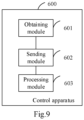
- control apparatus 600 includes:
- the apparatus further includes a processing module 603, and the processing module 603 is specifically configured to:
- processing module 603 is specifically configured to:
- the sending module 602 is further configured to: send a second control signal to the inverter when the battery cell temperature meets a preset power battery heating condition, where the second control signal is configured to control the inverter to convert a current provided by the power battery into an alternating current with a periodically changing amplitude, and the alternating current with a periodically changing amplitude is configured to supply power to the permanent magnet motor.
- processing module 603 is further configured to:
- an amplitude reference value in the reference value sequence of the d-axis component increases or decreases periodically.
- the processing module 603 is specifically configured to: the battery cell temperature is less than the lowest operating temperature of the power battery.
- An embodiment of the present application provides a power system, including: a power battery, an inverter, a permanent magnet motor, and a motor controller unit.
- the motor controller unit is configured to execute the control method described in the foregoing embodiments.
- change of frequency will induce a large amount of eddy current loss in a stator, a rotor core, and a permanent magnet of the motor, causing a large amount of heat of the motor.
- a heat dissipation apparatus may be installed in the motor to avoid the motor from burning.
- An embodiment of the present application provides an electric vehicle, including a power system, where the power system includes a power battery, an inverter, a permanent magnet motor, and a motor controller unit.
- the motor controller unit is configured to execute the control method described in the foregoing embodiments.
Landscapes
- Engineering & Computer Science (AREA)
- Power Engineering (AREA)
- Transportation (AREA)
- Mechanical Engineering (AREA)
- Life Sciences & Earth Sciences (AREA)
- Sustainable Development (AREA)
- Sustainable Energy (AREA)
- Secondary Cells (AREA)
- Electric Propulsion And Braking For Vehicles (AREA)
- Control Of Ac Motors In General (AREA)
Description
- The present application relates to the field of electric vehicle, and more specifically, to a control method, an apparatus, a power system, and an electric vehicle.
- An electric vehicle refers to a vehicle powered by a power battery. Due to limitation of material for power battery, the power battery can stably exert an optimal performance only under a rated ambient temperature. Therefore, when the electric vehicle is used in areas with lower ambient temperatures, the power battery needs to be heated to the rated ambient temperature.
- The internal resistance of the power battery is usually used to heat the power battery, and the stator winding of the motor is used as an energy storage element to provide heating current for the power battery. Since the internal resistance of the power battery is larger in a low-temperature environment, the heating efficiency of the power battery is higher.
-
CN111439132A discloses a control method and device of a permanent magnet motor, a power system and an electric vehicle. The energization frequency of the permanent magnet motor is set by acquiring system parameters such as the resonance bandwidth of the permanent magnet motor and the inherent frequency of a stator of the permanent magnet motor, and when a power battery meets a self-heating condition, alternating current with the energization frequency is used for supplying power to the permanent magnet motor, so that noise generated by the motor in the self-heating process of the power battery is reduced. -
CN106330011A discloses an electromagnetic interference suppression method and a device for a permanent magnet synchronous motor, a motor controller and an electric vehicle. The method comprises the following steps: through randomly changing a carrier cycle, a SVPWM (Space Vector Pulse Width Modulation) control signal with the switching frequency changed randomly is generated; and according to the SVPWM control signal with the switching frequency changed randomly, an inverter switch transistor in the motor controller is controlled, and electromagnetic interference generated when the motor controller drives the permanent magnet synchronous motor is thus suppressed. - However, in the foregoing method, magnetic field distribution of the motor during normal operation is changed, and an internal force of the motor is unbalanced, so that the motor generates a lot of noises when heating the power battery.
- The present application provides a method and an apparatus for controlling a permanent magnet motor, a power system and an electric vehicle therefor to reduce noises of the power battery during a self-heating process.
- According to a first aspect, a control method is provided in the present application, the method being applied to a power system, the power system including a power battery, a permanent magnet motor, and an inverter, where the method includes:
- obtaining a battery cell temperature of the power battery; and
- sending a first control signal to the inverter when the battery cell temperature meets a preset power battery heating condition, where the first control signal is configured to control the inverter to convert a current provided by the power battery into an alternating current with a randomly changing frequency, and the alternating current with a randomly changing frequency is configured to supply power to the permanent magnet motor.
- In some embodiments, before the sending a first control signal to the inverter, the method further includes:
- generating a plurality of set frequencies randomly, and determining duration of each set frequency according to each set frequency;
- determining a reference value sequence of a d-axis component according to the set frequencies and the duration of each set frequency, and setting a reference signal sequence of a q-axis component to a zero sequence; and
- generating the first control signal according to the reference value sequence of the d-axis component, the reference value sequence of the q-axis component, and a motor parameter of the permanent magnet motor.
- In the foregoing embodiments, a plurality of set frequencies are randomly generated, duration of each set frequency is determined according to each set frequency, and the first control signal is generated according to the set frequency and the duration of the set frequency, to control the inverter to convert a current provided by the power battery into an alternating current with a randomly changing frequency. New frequency components are introduced to evenly distribute originally concentrated radial electromagnetic forces to the entire stator, thereby reducing vibration noises during the heating process of the power battery.
- In some embodiments, the determining duration of each set frequency according to each set frequency specifically includes:
- taking an entire period length corresponding to the set frequency as the duration of the set frequency; or
- taking a half period length corresponding to the set frequency as the duration of the set frequency.
- In the foregoing embodiments, the duration of the set frequency is set to a half period length or an entire period length corresponding to the set frequency, so that it is convenient to detect an alternating current which is used for driving the motor, adjust the control signal in real time, and ensure noise suppression effects.
- In some embodiments, the method further includes:
sending a second control signal to the inverter when the battery cell temperature meets a preset power battery heating condition, where the second control signal is configured to control the inverter to convert a current provided by the power battery into an alternating current with a periodically changing amplitude, and the alternating current with a periodically changing amplitude is configured to supply power to the permanent magnet motor. - In the foregoing embodiments, the first control signal and the second control signal are sent to the inverter when the battery cell temperature of the power battery meets the heating condition of the power battery, to control the inverter to convert the current of the power battery into the alternating current with a randomly changing frequency and a periodically changing amplitude. New frequency components are introduced to further reduce vibration noises during the heating process of the power battery.
- In some embodiments, before the sending a second control signal to the inverter, the method further includes:
- determining a plurality of set amplitudes and duration of each set amplitude according to a heating parameter and a maximum noise threshold of the power battery;
- determining a reference value sequence of a d-axis component according to the set amplitudes and the duration of each set amplitude, and setting a reference value sequence of a q-axis component to a zero sequence; and
- generating the second control signal according to the reference value sequence of the d-axis component, the reference value sequence of the q-axis component, and a motor parameter of the permanent magnet motor.
- In the foregoing embodiments, the plurality of set amplitudes and duration of each set amplitude are determined according to the heating parameter and the maximum noise threshold of the power battery when the battery cell temperature of the power battery meets a self-heating condition of the battery, to generate the second control signal according to the set amplitudes and the duration, so that under common control of the first control signal and the second control signal, the inverter converts the current provided by the power battery into the alternating current with a randomly changing frequency and a periodically changing amplitude. More frequency components are introduced to evenly distribute originally concentrated radial electromagnetic forces to the entire stator, thereby greatly reducing vibration noises during the heating process of the power battery.
- In some embodiments, the heating parameter includes a heating rate and a heating duration.
- In some embodiments, an amplitude reference value in the reference value sequence of the d-axis component increases or decreases periodically.
- In some embodiments, the battery cell temperature meets a preset power battery heating condition specifically includes:
the battery cell temperature is less than the lowest operating temperature of the power battery. - According to a second aspect, a control apparatus is provided in the present application, including:
- an obtaining module, configured to obtain a battery cell temperature of a power battery; and
- a processing module, configured to send a first control signal to an inverter when the battery cell temperature meets a preset power battery heating condition, where the first control signal is configured to control the inverter to convert a current provided by the power battery into an alternating current with a randomly changing frequency, and the alternating current with a randomly changing frequency is configured to supply power to the permanent magnet motor.
- According to a third aspect, a power system is provided in the present application, including: a power battery, an inverter, a permanent magnet motor, and a motor controller unit, where the motor controller unit is configured to execute the control method according to the first aspect and optional solutions.
- According to a fourth aspect, an electric vehicle is provided in the present application, including a power system, where the power system includes a power battery, an inverter, a permanent magnet motor, and a motor controller unit, and the motor controller unit is configured to execute the control method according to the first aspect and optional solutions.
- The embodiments of the present application provide a control method, an apparatus, a power system, and an electric vehicle. A first control signal is sent to an inverter when a battery cell temperature of the power battery meets a heating condition of the power battery, where the first control signal is configured to control the inverter to convert a current provided by the power battery into an alternating current with a randomly changing frequency, and the alternating current with a randomly changing frequency is configured to supply power to a motor. New frequency components are introduced to evenly distribute originally concentrated radial electromagnetic forces to an entire stator, thereby reducing vibration noises during the heating process of the power battery. In addition, the first control signal and a second control signal are sent to the inverter, to control the inverter to convert the current provided by the power battery into the alternating current with a randomly changing frequency and a periodically changing amplitude. New frequency components are introduced to further reduce vibration noises during the heating process of the power battery.
-
-
FIG. 1 is a schematic structural diagram of a power system according to an embodiment of the present application; -
FIG. 2 is a schematic structural diagram of a power battery according to an embodiment of the present application; -
FIG. 3 is a schematic flowchart of a control method according to an embodiment of the present application; -
FIG. 4 is a schematic flowchart of vector control of a permanent magnet motor according to an embodiment of the present application; -
FIG. 5 is a schematic diagram of an alternating current for driving a motor according to an embodiment of the present application; -
FIG. 6 is a schematic diagram of one operating status of a power system according to an embodiment of the present application; -
FIG. 7 is a schematic diagram of another operating status of a power system according to an embodiment of the present application; -
FIG. 8 is a schematic diagram of an alternating current for driving a motor according to an embodiment of the present application; and -
FIG. 9 is a schematic structural diagram of a control apparatus according to an embodiment of the present application. - To make the objectives, technical solutions, and advantages of the present application clearer, the technical solutions in the present application will be clearly and completely described below with reference to the accompanying drawings in the present application. Obviously, the described embodiments are some of, rather than all of, the embodiments of the present application. All the other embodiments obtained by those of ordinary skill in the art based on the embodiments in the present application without creative efforts shall fall within the scope of protection of the present application.
- An electric vehicle refers to a vehicle powered by a power battery. As shown in
FIG. 1 , apower system 100 of the electric vehicle includes apower battery 10, aninverter 20, amotor 30, and a motor controller unit (MCU) 40. Positive and negative electrodes of thepower battery 10 are connected to a direct current side of theinverter 20, and an alternating current side of theinverter 20 is connected to a stator winding of themotor 30. Thepower battery 10 supplies power to themotor 30 through theinverter 20. TheMCU 40 has a plurality of input terminals for receiving motor operating status data. TheMCU 40 generates a pulse width modulation (PWM) signal according to the motor operating status data and operating status data of the power battery, and controls the voltage and current supplied by theinverter 20 to themotor 30, to control a speed of themotor 30, thereby achieving vehicle speed control. - As shown in
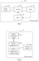
FIG. 2 , thepower battery 10 includes abattery module 101, a battery management system (BMS) 102, and anauxiliary structure 103. Thebattery module 101 is formed by a plurality of power battery cells in series and parallel. The battery cell is a core component of the power battery and is a source of electric energy provided by the power battery. Main functions of thebattery management system 102 are to perform charge and discharge management, high voltage control, battery state evaluation, battery data collection, battery protection, and battery thermal management. Generally, theauxiliary structure 103 includes an external frame, an electrical connection apparatus, an insulating component, and the like. The external frame plays the roles of protecting and supporting the battery module, the electrical connection apparatus plays a role of connecting with other electrical devices, such as connecting with the inverter, and the insulating component plays a role of insulation protection. - The thermal management function of the
battery management system 102 is used to ensure that the power battery operates within a suitable temperature range. The thermal management function is mainly to achieve accurate measurement and monitoring of the battery temperature, effective heat dissipation when a temperature of a battery group is too high, fast heating up under low temperature conditions, and ensure uniform distribution of temperature field of the battery group. The fast heating up under low temperature conditions means that in areas where the battery cell temperature is relatively low, the power battery needs to be heated to the rated battery cell temperature so that the power battery can stably exert an optimal performance. - Existing methods of heating power battery may include indirect heating and direct heating. The indirect heating refers to placing a heat source outside the power battery for heating. The indirect heating method may be air heating, liquid heating, heating film heating, and the like. For different heating sources, heating rates of the battery are also different. Since the battery is heated through an external heat source, and heat losses will occur on a heat transfer medium. Therefore, efficiency of indirect heating is not high.
- The direct heating refers to heating the power battery inside the power battery. A common direct heating method is heating through an internal resistance, specifically: the power battery is connected to the motor through an inverter, the motor rotor is fixed, a PWM signal is input to the control end of the inverter, the power battery and the stator winding form a closed loop, and the stator winding stores electric energy. Due to the inductance characteristics of the stator winding, the stator winding also provides alternating current to the battery, and the power battery is heated by the alternating current flowing through its internal resistance. Since the internal resistance of the power battery is larger in a low-temperature environment, the heating efficiency of the power battery is higher.
- However, in the existing method of heating through the internal resistance of the power battery, when the motor provides heating current for the power battery, the stator winding is used as an energy storage element to realize bus current alternating. The foregoing method changes magnetic field distribution of the motor during normal operation, which makes an internal force of the motor unbalanced, and easily causes vibration and noise of the motor, thereby causing NVH three indexes of the electric vehicle substandard. NVH is the abbreviation of Noise, Vibration, and Harshness. They are important indexes to measure comfort of a vehicle.
- To resolve the technical problems mentioned above, embodiments of the present application provide a control method, an apparatus, a power system, and an electric vehicle. An inventive concept of the present application is: setting a current of a q-axis or a voltage of a q-axis to 0, applying all voltages or currents to a d-axis, so that an output torque of the motor is 0, and an inductance of the motor is used for energy storage to realize a self-heating function of the battery. On the basis of controlling the voltage or current of the d-axis of the battery to be a sine wave, additional current harmonic components are introduced by randomly changing the frequency of the voltage or current of the d-axis. Thus radial electromagnetic forces of the motor are distributed to the stator more evenly under the condition of battery self-heating, so as to reduce noises of the motor under the condition of self-heating. In addition, by randomly changing the frequency of the voltage or current of the d-axis, and periodically changing the amplitude of the voltage or current of the d-axis, more current harmonic components may be introduced, so that the radial electromagnetic forces are evenly distributed to the entire stator, thereby greatly reducing vibration noises during the heating process of the power battery.
- As shown in
FIG. 3 , an embodiment of the present application provides a control method. The control method is applied to the power system shown inFIG. 1 . An execution body of the control method is an MCU, and the control method includes the following steps:
S201. The MCU obtains a battery cell temperature of the power battery. - A temperature sensor is deployed inside the power battery to monitor the battery cell temperature of the power battery in real time, and the temperature sensor transmits the detected battery cell temperature to the MCU.
- S202. The MCU sends a first control signal to the inverter when determining that the battery cell temperature meets a heating condition of the power battery.
- The heating condition of the power battery refers to that the battery cell temperature of the power battery is lower than the lowest operating temperature. If the battery cell temperature of the power battery is lower than the lowest operating temperature, it means that the battery cell temperature of the power battery meets the heating condition of the power battery. If the battery cell temperature of the power battery is higher than or equal to the lowest operating temperature, it means that the battery cell temperature of the power battery does not meet the heating condition of the power battery.
- The first control signal is configured to control the inverter to convert a current provided by the power battery into an alternating current with a randomly changing frequency, and the alternating current with a randomly changing frequency is configured to supply power to the permanent magnet motor, so that the power battery uses its own resistance for self-heating.
- According to the control method provided in the embodiments of the present application, the first control signal is generated when the battery cell temperature of the power battery meets the self-heating condition of the battery, so that the inverter converts the current provided by the power battery into the alternating current with a randomly changing frequency. New frequency components are introduced to evenly distribute originally concentrated radial electromagnetic forces to the entire stator, thereby reducing vibration noises during the heating process of the power battery.
- Another embodiment of the present application provides a control method. The control method is applied to the power system shown in
FIG. 1 . An execution body of the control method is an MCU, and the control method includes the following steps:
S301. The MCU obtains a battery cell temperature of the power battery. - A temperature sensor is deployed inside the power battery to monitor the battery cell temperature of the power battery in real time, and the temperature sensor transmits the detected battery cell temperature to the MCU.
- S302. The MCU generates a plurality of set frequencies randomly when determining that the battery cell temperature meets a heating condition of the power battery, and determines duration of each set frequency according to each set frequency.
- A plurality of set frequencies are generated randomly when the battery cell temperature is less than the lowest operating temperature of the power battery. The set frequency is a frequency of the current passing through the motor, namely, an alternating current at the set frequency is used to power the motor.
- As one specific method to determine the duration of each set frequency, an entire period length corresponding to the set frequency is taken as the duration of the set frequency. If the set frequency is f, the entire period length corresponding to the set frequency is 1/f, which means that each set frequency lasts for one period length.
- As another specific method to determine the duration of each set frequency, a half period length corresponding to the set frequency is taken as the duration of the set frequency. If the set frequency is f, the half period length corresponding to the set frequency is 1/2f, which means that each set frequency lasts for a half period length.
- S303. A reference value sequence of a d-axis component is determined according to the set frequencies and the duration of each set frequency, and a reference signal sequence of a q-axis component is set to a zero sequence.
- If the set frequencies generated randomly are f1, f2, ..., and fn, the duration corresponding to the set frequency f1 is t11, the duration corresponding to the set frequency f2 is t12, ..., and the duration corresponding to the set frequency fn is t1n.
- The reference value sequence of the d-axis component includes a plurality of reference values. Each reference value includes an amplitude reference value component, a frequency reference value component, and a duration reference value component. The amplitude reference value component may also be any value I1, the frequency reference value component is the set frequency, and the duration reference value component is the duration corresponding to the set frequency. Namely, the reference value sequence of the d-axis component is {(I1, f1, t11), (I1, f2, t12), ..., and (I1, fn, t1n)}.
- The reference value sequence of the q-axis component includes a plurality of reference values. Each reference value includes an amplitude reference value component, a frequency reference value component, and a duration reference value component. The amplitude reference value component, the frequency reference value component, and the duration reference value component are all zero. Namely, the reference value sequence of the q-axis component is {(0, 0, 0), (0, 0, 0), ..., and (0, 0, 0)}.
- S304. A first control signal is generated according to the reference value sequence of the d-axis component, the reference value sequence of the q-axis component, and a motor parameter of the permanent magnet motor.
- As shown in
FIG. 4 , the motor parameter of the permanent magnet motor includes an acceleration, a rotation speed, a position, and a stator current of the permanent magnet motor. - According to the rotation speed and position of the motor, a d-axis real-time component of the stator current and a q-axis real-time component of the stator current of the permanent magnet motor are obtained through a coordinate conversion of the stator current.
- An input value of a first proportional integral controller is generated according to the d-axis real-time component of the stator current, the acceleration of the permanent magnet motor, and a reference value of the d-axis component of the stator current. The first proportional integral controller outputs a d-axis reference value of a stator voltage.
- An input value of a second proportional integral controller is generated according to the q-axis real-time component of the stator current and a reference value of the q-axis component. The second proportional integral controller outputs a q-axis reference value of the stator voltage.
- Then a reference value of the stator voltage is obtained through a coordinate conversion of the d-axis reference value of the stator voltage, the q-axis reference value of the stator voltage, the rotation speed and position of the motor, and the first control signal is generated according to the reference value of the stator voltage. The first control signal is a space vector pulse width modulation (SVPWM) signal.
- S305. The MCU sends the first control signal to the inverter when determining that the battery cell temperature meets the heating condition of the power battery.
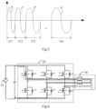
- The first control signal is configured to control the inverter to convert a current provided by the power battery into an alternating current with a randomly changing frequency. As shown in
FIG. 5 , the frequency of the alternating current in succession is f1, f2, ..., and fn, the duration corresponding to the frequency f1 is t11, the duration corresponding to the frequency f2 is t12, ..., the duration corresponding to the frequency fn is t1n, and an amplitude of the alternating current is I1. - The alternating current with a randomly changing frequency is configured to supply power to the permanent magnet motor, so that the power battery uses its own resistance for self-heating. The following describes a process of controlling the inverter to heat the power battery.
- As shown in
FIG. 6 , the first control signal controls the inverter. The MCU drives and closes a power switch device Sa on an A-phase bridge arm, a power switch device Sb' on a B-phase bridge arm, and a power switch device Sc' on a C-phase bridge arm, to form two discharge circuits. One of the discharge circuits is: power battery→Sa→ stator winding U→stator winding V→Sb'→power battery, and the other discharge circuit is: power battery→Sa→stator winding U→stator winding W→Sc'→power battery. The power battery discharges and converts electrical energy into electromagnetic energy on the three-phase stator winding, a motor rotor is at a standstill, the stator windings store energy, and an alternating bus current is realized at both bus ends of the power battery to heat the battery. - At the next time, the power switch device Sa on the A-phase bridge arm, the power switch device Sb' on the B-phase bridge arm, and the power switch device Sc' on the C-phase bridge arm are disconnected simultaneously. Due to the characteristic that the current in the stator winding cannot be changed suddenly, a backwash current loop thereof is shown in
FIG. 7 . Two backwash current loops are: power battery→diode D2 →stator winding U→stator winding V→diode D3→power battery, and power battery →diode D2→stator winding U→stator winding W→diode D5→power battery. During discharging and charging processes of the stator winding in the motor, current flows through the power battery, thereby heating the battery pack. - A magnitude of a heating current in a discharge loop is determined by a time when the power switch is closed, namely, the frequency f and the duty ratio D of a control signal for controlling the power switch device.
- According to the control method provided in the embodiments of the present application, the set frequencies are randomly generated when the battery cell temperature of the power battery meets the self-heating condition of the battery, and duration of each set frequency is determined according to the set frequencies. The first control signal is generated according to the set frequency and the duration, so that the inverter converts the current provided by the power battery into the alternating current with the set frequency. New frequency components are introduced to evenly distribute originally concentrated radial electromagnetic forces to the entire stator, thereby reducing vibration noises during the heating process of the power battery.
- Another embodiment of the present application provides a control method. The control method is applied to the power system shown in
FIG. 1 . An execution body of the control method is an MCU, and the control method includes the following steps:
S401. The MCU obtains a battery cell temperature of the power battery. - A temperature sensor is deployed inside the power battery to monitor the battery cell temperature of the power battery in real time, and the temperature sensor transmits the detected battery cell temperature to the MCU.
- S402. The MCU sends a first control signal to the inverter when determining that the battery cell temperature meets a heating condition of the power battery.
- When the battery cell temperature is lower than the lowest operating temperature, the first control signal is sent to the inverter. The first control signal is configured to control the inverter to convert a current provided by the power battery into an alternating current with a randomly changing frequency, and the alternating current with a randomly changing frequency is configured to supply power to the permanent magnet motor.
- S403. A second control signal is sent to the inverter when an ambient temperature meets a preset heating condition of the power battery.
- When the battery cell temperature is lower than the lowest operating temperature, the second control signal is also sent to the inverter. The second control signal is configured to control the inverter to convert a current provided by the power battery into an alternating current with a periodically changing amplitude, and the alternating current with a periodically changing amplitude is configured to supply power to the permanent magnet motor.
- As shown in
FIG. 8 , under the control of the first control signal and the second control signal, the inverter converts the current provided by the power battery into an alternating current with a randomly changing frequency and a periodically changing amplitude, so that the power battery uses its own resistance for self-heating. - According to the control method provided in the embodiments of the present application, the first control signal and the second control signal are generated when the battery cell temperature of the power battery meets the self-heating condition of the battery, so that the inverter converts the current provided by the power battery into the alternating current with a randomly changing frequency and a periodically changing amplitude. More frequency components are introduced to evenly distribute originally concentrated radial electromagnetic forces to the entire stator, thereby greatly reducing vibration noises during the heating process of the power battery.
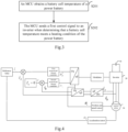
- Another embodiment of the present application provides a control method. The control method is applied to the power system shown in
FIG. 1 . An execution body of the control method is an MCU, and the control method includes the following steps: - 5501. The MCU obtains a battery cell temperature of the power battery.
- S502. The MCU generates a plurality of set frequencies randomly when determining that the battery cell temperature meets a heating condition of the power battery, and determines duration of each set frequency according to each set frequency.
- S503. A reference value sequence of a d-axis component is determined according to the set frequencies and the duration of each set frequency, and a reference signal sequence of a q-axis component is set to a zero sequence.
- S504. A first control signal is generated according to the reference value sequence of the d-axis component, the reference value sequence of the q-axis component, and a motor parameter of the permanent magnet motor.
- S505. The MCU sends the first control signal to the inverter when determining that the battery cell temperature meets the heating condition of the power battery.
- Steps S501 to S505 have been described in detail in the foregoing embodiments, and details are not described herein again.
- S506. A plurality of set amplitudes and duration of each set amplitude are determined according to a heating parameter and a maximum noise threshold of the power battery.
- The Heating parameter includes a heating rate and a heating duration. The maximum noise threshold refers to a threshold of vibration noise of the motor. The greater the set amplitude, the longer the duration, and the greater the heating rate, the shorter the heating duration.
- When determining the set amplitude, a current amplitude Id0 corresponding to a required heating rate under a constant amplitude and a constant frequency may be obtained. Id0 is used as an average value of variable amplitudes to generate a plurality of set amplitudes. The number of the set amplitudes is not limited herein.
- S507. A reference value sequence of a d-axis component is determined according to the set amplitudes and the duration of each set amplitude, and a reference value sequence of a q-axis component is set to a zero sequence.
- If the set amplitudes are I1, I2, ..., and In, the duration corresponding to the set frequency I1 is t21, the duration corresponding to the set frequency I2 is t22, ..., and the duration corresponding to the set frequency In is t2n.
- The reference value sequence of the d-axis component includes a plurality of reference values. Each reference value includes an amplitude reference value component, a frequency reference value component, and a duration reference value component. The frequency reference value component may also be any value f1, the amplitude reference value component is the set amplitude, and the duration reference value component is the duration corresponding to the set amplitude. Namely, the reference value sequence of the d-axis component is {(I1, f1, t21), (I2, f1, t22), ..., (In, f1, t2n), (I1, f1, t21), (I2, f1, t22),..., (In, f1, t2n),...}.
- The reference value sequence of the q-axis component includes a plurality of reference values. Each reference value includes an amplitude reference value component, a frequency reference value component, and a duration reference value component. The amplitude reference value component, the frequency reference value component, and the duration reference value component are all zero. Namely, the reference value sequence of the q-axis component is {(0, 0, 0), (0, 0, 0), ..., and (0, 0, 0)}.
- In some embodiments, the amplitude reference value in the reference value sequence of the d-axis component sequentially increases or decreases, namely, I1≤I2... ≤In, or I1≥I2...≥In. More frequency components may be introduced by using an alternating current with a periodically increasing amplitude or a periodically decreasing amplitude to power the motor, so that the originally concentrated radial electromagnetic forces is distributed evenly to the entire stator, thereby greatly reducing vibration noises during the heating process of the power battery.
- S508. A second control signal is generated according to the reference value sequence of the d-axis component, the reference value sequence of the q-axis component, and a motor parameter of the permanent magnet motor.
- The motor parameter of the permanent magnet motor includes a position, a speed, an acceleration, and a stator current of the motor. The method of generating the second control signal is the same as that described in
FIG. 4 , and details are not described herein again. - S509. The second control signal is sent to the inverter when an ambient temperature meets a preset heating condition of the power battery.
- When the battery cell temperature is lower than the lowest operating temperature, the second control signal is also sent to the inverter. The second control signal is configured to control the inverter to convert a current provided by the power battery into an alternating current with a periodically changing amplitude, and the alternating current with a periodically changing amplitude is configured to supply power to the permanent magnet motor.
- The period of amplitude change of the alternating current is:

- According to the control method provided in the embodiments of the present application, the set frequencies are randomly generated when the battery cell temperature of the power battery meets the self-heating condition of the battery, and duration of each set frequency is determined according to the set frequencies, so that the first control signal is generated according to the set frequency and the duration. A plurality of set amplitudes and duration of each set amplitude are determined according to the heating parameter and the maximum noise threshold of the power battery, so that the second control signal is generated according to the set amplitude and the duration. Under common control of the first control signal and the second control signal, the inverter converts the current provided by the power battery into the alternating current with a randomly changing frequency and a periodically changing amplitude. More frequency components are introduced to evenly distribute originally concentrated radial electromagnetic forces to the entire stator, thereby greatly reducing vibration noises during the heating process of the power battery.
- As shown in
FIG. 9 , the present application provides acontrol apparatus 600, and thecontrol apparatus 600 includes: - an obtaining
module 601, configured to obtain a battery cell temperature of a power battery; and - a sending
module 602, configured to send a first control signal to an inverter when the battery cell temperature meets a preset power battery heating condition, where the first control signal is configured to control the inverter to convert a current provided by the power battery into an alternating current with a randomly changing frequency, and the alternating current with a randomly changing frequency is configured to supply power to the permanent magnet motor. - In some embodiments, the apparatus further includes a
processing module 603, and theprocessing module 603 is specifically configured to: - generate a plurality of set frequencies randomly, and determine duration of each set frequency according to each set frequency;
- determine a reference value sequence of a d-axis component according to the set frequencies and the duration of each set frequency, and set a reference signal sequence of a q-axis component to a zero sequence; and
- generate the first control signal according to the reference value sequence of the d-axis component, the reference value sequence of the q-axis component, and a motor parameter of the permanent magnet motor.
- In some embodiments, the
processing module 603 is specifically configured to: - take an entire period length corresponding to the set frequency as the duration of the set frequency; or
- take a half period length corresponding to the set frequency as the duration of the set frequency.
- In some embodiments, the sending
module 602 is further configured to:
send a second control signal to the inverter when the battery cell temperature meets a preset power battery heating condition, where the second control signal is configured to control the inverter to convert a current provided by the power battery into an alternating current with a periodically changing amplitude, and the alternating current with a periodically changing amplitude is configured to supply power to the permanent magnet motor. - In some embodiments, the
processing module 603 is further configured to: - determine a plurality of set amplitudes and duration of each set amplitude according to a heating parameter and a maximum noise threshold of the power battery;
- determine a reference value sequence of a d-axis component according to the set amplitudes and the duration of each set amplitude, and set a reference value sequence of a q-axis component to a zero sequence; and
- generate the second control signal according to the reference value sequence of the d-axis component, the reference value sequence of the q-axis component, and a motor parameter of the permanent magnet motor.
- In some embodiments, the heating parameter includes a heating rate and a heating duration.
- In some embodiments, an amplitude reference value in the reference value sequence of the d-axis component increases or decreases periodically.
- In some embodiments, the
processing module 603 is specifically configured to:
the battery cell temperature is less than the lowest operating temperature of the power battery. - An embodiment of the present application provides a power system, including: a power battery, an inverter, a permanent magnet motor, and a motor controller unit. The motor controller unit is configured to execute the control method described in the foregoing embodiments. However, change of frequency will induce a large amount of eddy current loss in a stator, a rotor core, and a permanent magnet of the motor, causing a large amount of heat of the motor. A heat dissipation apparatus may be installed in the motor to avoid the motor from burning.
- An embodiment of the present application provides an electric vehicle, including a power system, where the power system includes a power battery, an inverter, a permanent magnet motor, and a motor controller unit. The motor controller unit is configured to execute the control method described in the foregoing embodiments.
- It should finally be noted that the foregoing embodiments are merely intended for illustrating rather than limiting the technical solutions of the present application. Although the present application is described in detail with reference to the foregoing embodiments, those of ordinary skill in the art should understand that they may still make modifications to the technical solutions described in the foregoing embodiments, or make equivalent substitutions to some or all technical features thereof; but these modifications or substitutions can be made to the respective technical solutions without departing from the technical solutions as defined by the appended claims.
Claims (13)
- A control method, the method being applied to a power system (100), the power system (100) comprising a power battery (10), a permanent magnet motor (30), and an inverter (20), wherein the method comprising:obtaining (S201) a battery cell temperature of the power battery (10); andsending (S202) a first control signal to the inverter (20) when the battery cell temperature meets a preset power battery heating condition, whereinthe first control signal is configured to control the inverter (20) to convert a current provided by the power battery (10) into an alternating current with a randomly changing frequency, andthe alternating current with a randomly changing frequency is configured to supply power to the permanent magnet motor (30);being the method characterized in that before the sending a first control signal to the inverter (20), the method further comprises:generating (S302) a plurality of set frequencies randomly, and determining duration of each set frequency according to each set frequency;determining (S303) a reference value sequence of a d-axis component according to the set frequencies and the duration of each set frequency, and setting a reference value sequence of a q-axis component to a zero sequence; andgenerating (S304) the first control signal according to the reference value sequence of the d-axis component, the reference value sequence of the q-axis component, and a motor parameter of the permanent magnet motor (30).
- The method according to claim 1, wherein the determining duration of each set frequency according to each set frequency comprises:taking an entire period length corresponding to the set frequency as the duration of the set frequency; ortaking a half period length corresponding to the set frequency as the duration of the set frequency.
- The method according to any one of claims 1 to 2, wherein the method further comprises:
sending (S403) a second control signal to the inverter (20) when the battery cell temperature meets the preset power battery heating condition, wherein the second control signal is configured to control the inverter (20) to convert a current provided by the power battery (10) into an alternating current with a periodically changing amplitude, and the alternating current with a periodically changing amplitude is configured to supply power to the permanent magnet motor (30). - The method according to claim 3, wherein before the sending a second control signal to the inverter (20), the method further comprises:determining (S506) a plurality of set amplitudes and duration of each set amplitude according to a heating parameter and a maximum noise threshold of the power battery;determining (S507) a reference value sequence of a d-axis component according to the set amplitudes and the duration of each set amplitude, and setting a reference value sequence of a q-axis component to a zero sequence; andgenerating (S508) the second control signal according to the reference value sequence of the d-axis component, the reference value sequence of the q-axis component, and a motor parameter of the permanent magnet motor (30).
- The method according to claim 4, wherein the heating parameter comprises a heating rate and a heating duration.
- The method according to claim 4 or 5, wherein an amplitude reference value in the reference value sequence of the d-axis component increases or decreases periodically.
- The method according to any one of claims 1 to 6, wherein the battery cell temperature meets a preset power battery heating condition comprises:
the battery cell temperature is less than the lowest operating temperature of the power battery (10). - A control apparatus (600), comprising:an obtaining module (601), configured to obtain a battery cell temperature of a power battery (10); anda sending module (602), configured to send a first control signal to an inverter (20) when the battery cell temperature meets a preset power battery heating condition, wherein the first control signal is configured to control the inverter (20) to convert a current provided by the power battery (10) into an alternating current with a randomly changing frequency, and the alternating current with a randomly changing frequency is configured to supply power to a permanent magnet motor (30);wherein the apparatus (600) further comprises a processing module (603), the processing module (603) is configured to:generate a plurality of set frequencies randomly, and determine duration of each set frequency according to each set frequency;determine a reference value sequence of a d-axis component according to the set frequencies and the duration of each set frequency, and set a reference value sequence of a q-axis component to a zero sequence; andgenerate the first control signal according to the reference value sequence of the d-axis component, the reference value sequence of the q-axis component, and a motor parameter of the permanent magnet motor (30).
- The apparatus according to claim 8, wherein the sending module (602) is further configured to:
send a second control signal to the inverter when the battery cell temperature meets the preset power battery heating condition, wherein the second control signal is configured to control the inverter to convert a current provided by the power battery into an alternating current with a periodically changing amplitude, and the alternating current with a periodically changing amplitude is configured to supply power to the permanent magnet motor (30). - The apparatus according to claim 9, wherein the processing module (603) is configured to:determine a plurality of set amplitudes and duration of each set amplitude according to a heating parameter and a maximum noise threshold of the power battery;determine a reference value sequence of a d-axis component according to the set amplitudes and the duration of each set amplitude, and set a reference value sequence of a q-axis component to a zero sequence; andgenerate the second control signal according to the reference value sequence of the d-axis component, the reference value sequence of the q-axis component, and a motor parameter of the permanent magnet motor (30).
- The apparatus according to any one of claims 8 to 10, wherein the battery cell temperature meets a preset power battery heating condition comprises:
the battery cell temperature is less than the lowest operating temperature of the power battery. - A power system, comprising: a power battery (10), an inverter (20), a permanent magnet motor (30), and a motor controller unit (40), wherein the motor controller unit (40) is configured to execute the control method according to any one of claims 1 to 7.
- An electric vehicle, comprising a power system (100), wherein the power system (100) comprises a power battery (10), an inverter (20), a permanent magnet motor (30), and a motor controller unit (40), and the motor controller unit (40) is configured to execute the control method according to any one of claims 1 to 7.
Applications Claiming Priority (2)
| Application Number | Priority Date | Filing Date | Title |
|---|---|---|---|
| CN202011554389.6A CN114670656B (en) | 2020-12-24 | 2020-12-24 | Control method, device, power system and electric vehicle |
| PCT/CN2021/073996 WO2022134266A1 (en) | 2020-12-24 | 2021-01-27 | Control method and apparatus, power system and electric vehicle |
Publications (4)
| Publication Number | Publication Date |
|---|---|
| EP4046862A4 EP4046862A4 (en) | 2022-08-24 |
| EP4046862A1 EP4046862A1 (en) | 2022-08-24 |
| EP4046862C0 EP4046862C0 (en) | 2024-06-12 |
| EP4046862B1 true EP4046862B1 (en) | 2024-06-12 |
Family
ID=82118274
Family Applications (1)
| Application Number | Title | Priority Date | Filing Date |
|---|---|---|---|
| EP21766558.7A Active EP4046862B1 (en) | 2020-12-24 | 2021-01-27 | Control method and apparatus, power system and electric vehicle |
Country Status (2)
| Country | Link |
|---|---|
| US (1) | US11418143B2 (en) |
| EP (1) | EP4046862B1 (en) |
Families Citing this family (5)
| Publication number | Priority date | Publication date | Assignee | Title |
|---|---|---|---|---|
| CN115566969A (en) * | 2022-10-13 | 2023-01-03 | 广汽埃安新能源汽车股份有限公司 | Method, device, electronic device and medium for battery heating by electric motor |
| CN115923597B (en) * | 2022-11-02 | 2025-07-25 | 臻驱科技(上海)股份有限公司 | Power battery heating method and device and power battery |
| CN115832531A (en) * | 2022-12-16 | 2023-03-21 | 中国第一汽车股份有限公司 | Battery heating method and device, storage medium, processor and vehicle |
| CN116865616A (en) * | 2023-06-27 | 2023-10-10 | 浙江吉利控股集团有限公司 | Vehicle control method and vehicle |
| CN120756346B (en) * | 2025-09-09 | 2026-01-20 | 潍柴动力股份有限公司 | Heating control method and heating control device for power battery and vehicle |
Family Cites Families (21)
| Publication number | Priority date | Publication date | Assignee | Title |
|---|---|---|---|---|
| JP2000184731A (en) | 1998-12-18 | 2000-06-30 | Meidensha Corp | Power converter |
| US7447252B2 (en) * | 2000-05-01 | 2008-11-04 | Andrzej Partyka | Overhead reduction in frequency hopping system for intermittent transmission |
| US7382102B2 (en) | 2005-06-13 | 2008-06-03 | Chrysler Llc | Heating of batteries using reactive power |
| US8373372B2 (en) | 2009-09-25 | 2013-02-12 | Ut-Battelle, Llc | Electrical motor/generator drive apparatus and method |
| EP2579452B1 (en) | 2010-06-07 | 2015-05-27 | Toyota Jidosha Kabushiki Kaisha | Control method and control device for an electric power regulator |
| JP5849917B2 (en) | 2012-09-28 | 2016-02-03 | 株式会社豊田自動織機 | Battery temperature rise control device for electric vehicle |
| CN103560304B (en) | 2013-11-19 | 2016-05-04 | 东风汽车公司 | A kind of electric automobile power battery group method for heating and controlling |
| JP6168092B2 (en) * | 2015-04-10 | 2017-07-26 | トヨタ自動車株式会社 | In-vehicle secondary battery cooling system |
| JP6380304B2 (en) * | 2015-09-03 | 2018-08-29 | トヨタ自動車株式会社 | Hybrid car |
| CN106330011A (en) * | 2016-09-05 | 2017-01-11 | 北京新能源汽车股份有限公司 | Electromagnetic interference suppression method and device for motor, motor controller and electric vehicle |
| JP6741904B2 (en) * | 2016-12-09 | 2020-08-19 | 株式会社デンソー | Drive and car |
| CN111347935B (en) | 2018-12-21 | 2021-10-22 | 比亚迪股份有限公司 | A vehicle and its power battery heating device and method |
| CN110962631B (en) | 2018-12-29 | 2020-11-17 | 宁德时代新能源科技股份有限公司 | Battery heating system and control method thereof |
| CN110048192A (en) * | 2019-03-20 | 2019-07-23 | 石不凡 | A kind of power battery preheating method |
| KR102768452B1 (en) * | 2019-04-05 | 2025-02-13 | 주식회사 엘지에너지솔루션 | Apparatus and method for managing battery |
| KR102712337B1 (en) * | 2019-04-24 | 2024-10-02 | 현대자동차주식회사 | Apparatus and method for controlling inverter driving motor |
| CN110932585A (en) | 2019-12-10 | 2020-03-27 | 国网河南省电力公司电力科学研究院 | Modulation method and device for reducing ultrahigh harmonic amplitude at converter switching frequency |
| US11290045B2 (en) * | 2020-05-05 | 2022-03-29 | Nio Usa, Inc. | Devices, systems, and methods for self-heating batteries |
| CN111439132B (en) * | 2020-06-15 | 2020-11-17 | 江苏时代新能源科技有限公司 | Control method and device of permanent magnet motor, power system and electric automobile |
| CN112078433A (en) | 2020-08-31 | 2020-12-15 | 上海交通大学 | Low temperature preheating device for vehicle power battery and control method thereof |
| CN112103595A (en) | 2020-08-31 | 2020-12-18 | 上海交通大学 | Vehicle power battery preheating device and control method thereof |
-
2021
- 2021-01-27 EP EP21766558.7A patent/EP4046862B1/en active Active
- 2021-11-18 US US17/529,917 patent/US11418143B2/en active Active
Also Published As
| Publication number | Publication date |
|---|---|
| EP4046862A4 (en) | 2022-08-24 |
| EP4046862A1 (en) | 2022-08-24 |
| EP4046862C0 (en) | 2024-06-12 |
| US11418143B2 (en) | 2022-08-16 |
| US20220209707A1 (en) | 2022-06-30 |
Similar Documents
| Publication | Publication Date | Title |
|---|---|---|
| EP4046862B1 (en) | Control method and apparatus, power system and electric vehicle | |
| JP7488288B2 (en) | Battery pack heating method, battery heating system and power consumption device | |
| EP4067161B1 (en) | Control method, apparatus, power system and electric vehicle | |
| JP7844800B2 (en) | Heating system for heating power batteries, and electric vehicles | |
| EP3758132B1 (en) | Switch control device and method, motor controller, and battery pack heating control system | |
| US20220077518A1 (en) | Vehicle and power battery heating apparatus and method thereof | |
| US20240178690A1 (en) | Charge/discharge circuit, system, and control method | |
| US11916504B2 (en) | Energy conversion device and vehicle | |
| US20220080858A1 (en) | Vehicle and power battery heating apparatus and method therefor | |
| CN112977173A (en) | Electric automobile and power battery pulse heating system and heating method thereof | |
| US20210061128A1 (en) | System and method for increasing temperature of battery using motor driving system | |
| US11606058B2 (en) | Motor, control method, power system, and electric vehicle | |
| EP4043275A1 (en) | Electric motor, power system, control method, and electric vehicle | |
| EP4613547A1 (en) | Energy conversion device and vehicle | |
| CN109164384B (en) | Motor stator insulation aging test device and test method | |
| CN117734527A (en) | Battery heating parameter determining method, controller, system, vehicle and medium | |
| CN120792617A (en) | Self-heating control method and device for power battery, electric automobile and medium | |
| CN117325719A (en) | Voltage feedback battery preheating method of integrated electric drive system | |
| CN118700899A (en) | Battery heating circuit, control method and controller, power system, and electrical equipment | |
| Huang et al. | Performance test and analysis of key components of pure electric vehicles |
Legal Events
| Date | Code | Title | Description |
|---|---|---|---|
| STAA | Information on the status of an ep patent application or granted ep patent |
Free format text: STATUS: UNKNOWN |
|
| STAA | Information on the status of an ep patent application or granted ep patent |
Free format text: STATUS: THE INTERNATIONAL PUBLICATION HAS BEEN MADE |
|
| PUAI | Public reference made under article 153(3) epc to a published international application that has entered the european phase |
Free format text: ORIGINAL CODE: 0009012 |
|
| STAA | Information on the status of an ep patent application or granted ep patent |
Free format text: STATUS: REQUEST FOR EXAMINATION WAS MADE |
|
| 17P | Request for examination filed |
Effective date: 20210917 |
|
| A4 | Supplementary search report drawn up and despatched |
Effective date: 20220525 |
|
| AK | Designated contracting states |
Kind code of ref document: A1 Designated state(s): AL AT BE BG CH CY CZ DE DK EE ES FI FR GB GR HR HU IE IS IT LI LT LU LV MC MK MT NL NO PL PT RO RS SE SI SK SM TR |
|
| STAA | Information on the status of an ep patent application or granted ep patent |
Free format text: STATUS: EXAMINATION IS IN PROGRESS |
|
| 17Q | First examination report despatched |
Effective date: 20221121 |
|
| REG | Reference to a national code |
Ref country code: DE Ref legal event code: R079 Free format text: PREVIOUS MAIN CLASS: B60L0058270000 Ipc: H02P0021220000 Ref document number: 602021014432 Country of ref document: DE |
|
| GRAP | Despatch of communication of intention to grant a patent |
Free format text: ORIGINAL CODE: EPIDOSNIGR1 |
|
| STAA | Information on the status of an ep patent application or granted ep patent |
Free format text: STATUS: GRANT OF PATENT IS INTENDED |
|
| RIC1 | Information provided on ipc code assigned before grant |
Ipc: B60L 58/24 20190101ALI20240216BHEP Ipc: B60L 1/02 20060101ALI20240216BHEP Ipc: B60L 58/27 20190101ALI20240216BHEP Ipc: H02P 29/68 20160101ALI20240216BHEP Ipc: H02P 27/08 20060101ALI20240216BHEP Ipc: H02P 21/00 20160101ALI20240216BHEP Ipc: H02P 21/22 20160101AFI20240216BHEP |
|
| DAV | Request for validation of the european patent (deleted) | ||
| DAX | Request for extension of the european patent (deleted) | ||
| INTG | Intention to grant announced |
Effective date: 20240322 |
|
| GRAS | Grant fee paid |
Free format text: ORIGINAL CODE: EPIDOSNIGR3 |
|
| GRAA | (expected) grant |
Free format text: ORIGINAL CODE: 0009210 |
|
| STAA | Information on the status of an ep patent application or granted ep patent |
Free format text: STATUS: THE PATENT HAS BEEN GRANTED |
|
| AK | Designated contracting states |
Kind code of ref document: B1 Designated state(s): AL AT BE BG CH CY CZ DE DK EE ES FI FR GB GR HR HU IE IS IT LI LT LU LV MC MK MT NL NO PL PT RO RS SE SI SK SM TR |
|
| REG | Reference to a national code |
Ref country code: GB Ref legal event code: FG4D |
|
| REG | Reference to a national code |
Ref country code: CH Ref legal event code: EP |
|
| REG | Reference to a national code |
Ref country code: IE Ref legal event code: FG4D |
|
| REG | Reference to a national code |
Ref country code: DE Ref legal event code: R096 Ref document number: 602021014432 Country of ref document: DE |
|
| U01 | Request for unitary effect filed |
Effective date: 20240705 |
|
| U07 | Unitary effect registered |
Designated state(s): AT BE BG DE DK EE FI FR IT LT LU LV MT NL PT SE SI Effective date: 20240715 |
|
| RAP2 | Party data changed (patent owner data changed or rights of a patent transferred) |
Owner name: CONTEMPORARY AMPEREX TECHNOLOGY(HONG KONG) LIMITED |
|
| U1K | Transfer of rights of the unitary patent after the registration of the unitary effect |
Owner name: CONTEMPORARY AMPEREX TECHNOLOGY(HONG KONG) LIMITED; HK |
|
| PG25 | Lapsed in a contracting state [announced via postgrant information from national office to epo] |
Ref country code: HR Free format text: LAPSE BECAUSE OF FAILURE TO SUBMIT A TRANSLATION OF THE DESCRIPTION OR TO PAY THE FEE WITHIN THE PRESCRIBED TIME-LIMIT Effective date: 20240612 |
|
| PG25 | Lapsed in a contracting state [announced via postgrant information from national office to epo] |
Ref country code: GR Free format text: LAPSE BECAUSE OF FAILURE TO SUBMIT A TRANSLATION OF THE DESCRIPTION OR TO PAY THE FEE WITHIN THE PRESCRIBED TIME-LIMIT Effective date: 20240913 |
|
| PG25 | Lapsed in a contracting state [announced via postgrant information from national office to epo] |
Ref country code: ES Free format text: LAPSE BECAUSE OF FAILURE TO SUBMIT A TRANSLATION OF THE DESCRIPTION OR TO PAY THE FEE WITHIN THE PRESCRIBED TIME-LIMIT Effective date: 20240612 |
|
| PG25 | Lapsed in a contracting state [announced via postgrant information from national office to epo] |
Ref country code: NO Free format text: LAPSE BECAUSE OF FAILURE TO SUBMIT A TRANSLATION OF THE DESCRIPTION OR TO PAY THE FEE WITHIN THE PRESCRIBED TIME-LIMIT Effective date: 20240912 Ref country code: HR Free format text: LAPSE BECAUSE OF FAILURE TO SUBMIT A TRANSLATION OF THE DESCRIPTION OR TO PAY THE FEE WITHIN THE PRESCRIBED TIME-LIMIT Effective date: 20240612 Ref country code: GR Free format text: LAPSE BECAUSE OF FAILURE TO SUBMIT A TRANSLATION OF THE DESCRIPTION OR TO PAY THE FEE WITHIN THE PRESCRIBED TIME-LIMIT Effective date: 20240913 Ref country code: ES Free format text: LAPSE BECAUSE OF FAILURE TO SUBMIT A TRANSLATION OF THE DESCRIPTION OR TO PAY THE FEE WITHIN THE PRESCRIBED TIME-LIMIT Effective date: 20240612 Ref country code: RS Free format text: LAPSE BECAUSE OF FAILURE TO SUBMIT A TRANSLATION OF THE DESCRIPTION OR TO PAY THE FEE WITHIN THE PRESCRIBED TIME-LIMIT Effective date: 20240912 |
|
| PG25 | Lapsed in a contracting state [announced via postgrant information from national office to epo] |
Ref country code: PL Free format text: LAPSE BECAUSE OF FAILURE TO SUBMIT A TRANSLATION OF THE DESCRIPTION OR TO PAY THE FEE WITHIN THE PRESCRIBED TIME-LIMIT Effective date: 20240612 |
|
| PG25 | Lapsed in a contracting state [announced via postgrant information from national office to epo] |
Ref country code: IS Free format text: LAPSE BECAUSE OF FAILURE TO SUBMIT A TRANSLATION OF THE DESCRIPTION OR TO PAY THE FEE WITHIN THE PRESCRIBED TIME-LIMIT Effective date: 20241012 |
|
| PG25 | Lapsed in a contracting state [announced via postgrant information from national office to epo] |
Ref country code: CZ Free format text: LAPSE BECAUSE OF FAILURE TO SUBMIT A TRANSLATION OF THE DESCRIPTION OR TO PAY THE FEE WITHIN THE PRESCRIBED TIME-LIMIT Effective date: 20240612 |
|
| PG25 | Lapsed in a contracting state [announced via postgrant information from national office to epo] |
Ref country code: SK Free format text: LAPSE BECAUSE OF FAILURE TO SUBMIT A TRANSLATION OF THE DESCRIPTION OR TO PAY THE FEE WITHIN THE PRESCRIBED TIME-LIMIT Effective date: 20240612 Ref country code: RO Free format text: LAPSE BECAUSE OF FAILURE TO SUBMIT A TRANSLATION OF THE DESCRIPTION OR TO PAY THE FEE WITHIN THE PRESCRIBED TIME-LIMIT Effective date: 20240612 |
|
| PG25 | Lapsed in a contracting state [announced via postgrant information from national office to epo] |
Ref country code: SM Free format text: LAPSE BECAUSE OF FAILURE TO SUBMIT A TRANSLATION OF THE DESCRIPTION OR TO PAY THE FEE WITHIN THE PRESCRIBED TIME-LIMIT Effective date: 20240612 |
|
| PG25 | Lapsed in a contracting state [announced via postgrant information from national office to epo] |
Ref country code: SM Free format text: LAPSE BECAUSE OF FAILURE TO SUBMIT A TRANSLATION OF THE DESCRIPTION OR TO PAY THE FEE WITHIN THE PRESCRIBED TIME-LIMIT Effective date: 20240612 Ref country code: SK Free format text: LAPSE BECAUSE OF FAILURE TO SUBMIT A TRANSLATION OF THE DESCRIPTION OR TO PAY THE FEE WITHIN THE PRESCRIBED TIME-LIMIT Effective date: 20240612 Ref country code: RO Free format text: LAPSE BECAUSE OF FAILURE TO SUBMIT A TRANSLATION OF THE DESCRIPTION OR TO PAY THE FEE WITHIN THE PRESCRIBED TIME-LIMIT Effective date: 20240612 Ref country code: PL Free format text: LAPSE BECAUSE OF FAILURE TO SUBMIT A TRANSLATION OF THE DESCRIPTION OR TO PAY THE FEE WITHIN THE PRESCRIBED TIME-LIMIT Effective date: 20240612 Ref country code: IS Free format text: LAPSE BECAUSE OF FAILURE TO SUBMIT A TRANSLATION OF THE DESCRIPTION OR TO PAY THE FEE WITHIN THE PRESCRIBED TIME-LIMIT Effective date: 20241012 Ref country code: CZ Free format text: LAPSE BECAUSE OF FAILURE TO SUBMIT A TRANSLATION OF THE DESCRIPTION OR TO PAY THE FEE WITHIN THE PRESCRIBED TIME-LIMIT Effective date: 20240612 |
|
| U20 | Renewal fee for the european patent with unitary effect paid |
Year of fee payment: 5 Effective date: 20250122 |
|
| PLBE | No opposition filed within time limit |
Free format text: ORIGINAL CODE: 0009261 |
|
| STAA | Information on the status of an ep patent application or granted ep patent |
Free format text: STATUS: NO OPPOSITION FILED WITHIN TIME LIMIT |
|
| 26N | No opposition filed |
Effective date: 20250313 |
|
| REG | Reference to a national code |
Ref country code: CH Ref legal event code: PL |
|
| PG25 | Lapsed in a contracting state [announced via postgrant information from national office to epo] |
Ref country code: MC Free format text: LAPSE BECAUSE OF FAILURE TO SUBMIT A TRANSLATION OF THE DESCRIPTION OR TO PAY THE FEE WITHIN THE PRESCRIBED TIME-LIMIT Effective date: 20240612 |
|
| GBPC | Gb: european patent ceased through non-payment of renewal fee |
Effective date: 20250127 |
|
| PG25 | Lapsed in a contracting state [announced via postgrant information from national office to epo] |
Ref country code: GB Free format text: LAPSE BECAUSE OF NON-PAYMENT OF DUE FEES Effective date: 20250127 |
|
| PG25 | Lapsed in a contracting state [announced via postgrant information from national office to epo] |
Ref country code: CH Free format text: LAPSE BECAUSE OF NON-PAYMENT OF DUE FEES Effective date: 20250131 |
|
| PG25 | Lapsed in a contracting state [announced via postgrant information from national office to epo] |
Ref country code: IE Free format text: LAPSE BECAUSE OF NON-PAYMENT OF DUE FEES Effective date: 20250127 |
|
| U20 | Renewal fee for the european patent with unitary effect paid |
Year of fee payment: 6 Effective date: 20260127 |