EP4046837A1 - Luftdiffusor - Google Patents
Luftdiffusor Download PDFInfo
- Publication number
- EP4046837A1 EP4046837A1 EP22155239.1A EP22155239A EP4046837A1 EP 4046837 A1 EP4046837 A1 EP 4046837A1 EP 22155239 A EP22155239 A EP 22155239A EP 4046837 A1 EP4046837 A1 EP 4046837A1
- Authority
- EP
- European Patent Office
- Prior art keywords
- type
- slat
- movable
- actuator element
- air diffuser
- Prior art date
- Legal status (The legal status is an assumption and is not a legal conclusion. Google has not performed a legal analysis and makes no representation as to the accuracy of the status listed.)
- Withdrawn
Links
Images

Classifications
-
- B—PERFORMING OPERATIONS; TRANSPORTING
- B60—VEHICLES IN GENERAL
- B60H—ARRANGEMENTS OF HEATING, COOLING, VENTILATING OR OTHER AIR-TREATING DEVICES SPECIALLY ADAPTED FOR PASSENGER OR GOODS SPACES OF VEHICLES
- B60H1/00—Heating, cooling or ventilating devices
- B60H1/34—Nozzles; Air-diffusers
- B60H1/3414—Nozzles; Air-diffusers with means for adjusting the air stream direction
- B60H1/3421—Nozzles; Air-diffusers with means for adjusting the air stream direction using only pivoting shutters
-
- F—MECHANICAL ENGINEERING; LIGHTING; HEATING; WEAPONS; BLASTING
- F24—HEATING; RANGES; VENTILATING
- F24F—AIR-CONDITIONING; AIR-HUMIDIFICATION; VENTILATION; USE OF AIR CURRENTS FOR SCREENING
- F24F13/00—Details common to, or for air-conditioning, air-humidification, ventilation or use of air currents for screening
- F24F13/08—Air-flow control members, e.g. louvres, grilles, flaps or guide plates
- F24F13/10—Air-flow control members, e.g. louvres, grilles, flaps or guide plates movable, e.g. dampers
- F24F13/14—Air-flow control members, e.g. louvres, grilles, flaps or guide plates movable, e.g. dampers built up of tilting members, e.g. louvre
- F24F13/1426—Air-flow control members, e.g. louvres, grilles, flaps or guide plates movable, e.g. dampers built up of tilting members, e.g. louvre characterised by actuating means
-
- G—PHYSICS
- G02—OPTICS
- G02F—OPTICAL DEVICES OR ARRANGEMENTS FOR THE CONTROL OF LIGHT BY MODIFICATION OF THE OPTICAL PROPERTIES OF THE MEDIA OF THE ELEMENTS INVOLVED THEREIN; NON-LINEAR OPTICS; FREQUENCY-CHANGING OF LIGHT; OPTICAL LOGIC ELEMENTS; OPTICAL ANALOGUE/DIGITAL CONVERTERS
- G02F1/00—Devices or arrangements for the control of the intensity, colour, phase, polarisation or direction of light arriving from an independent light source, e.g. switching, gating or modulating; Non-linear optics
- G02F1/35—Non-linear optics
- G02F1/3501—Constructional details or arrangements of non-linear optical devices, e.g. shape of non-linear crystals
- G02F1/3509—Shape, e.g. shape of end face
-
- G—PHYSICS
- G02—OPTICS
- G02F—OPTICAL DEVICES OR ARRANGEMENTS FOR THE CONTROL OF LIGHT BY MODIFICATION OF THE OPTICAL PROPERTIES OF THE MEDIA OF THE ELEMENTS INVOLVED THEREIN; NON-LINEAR OPTICS; FREQUENCY-CHANGING OF LIGHT; OPTICAL LOGIC ELEMENTS; OPTICAL ANALOGUE/DIGITAL CONVERTERS
- G02F1/00—Devices or arrangements for the control of the intensity, colour, phase, polarisation or direction of light arriving from an independent light source, e.g. switching, gating or modulating; Non-linear optics
- G02F1/35—Non-linear optics
- G02F1/3528—Non-linear optics for producing a supercontinuum
-
- G—PHYSICS
- G02—OPTICS
- G02F—OPTICAL DEVICES OR ARRANGEMENTS FOR THE CONTROL OF LIGHT BY MODIFICATION OF THE OPTICAL PROPERTIES OF THE MEDIA OF THE ELEMENTS INVOLVED THEREIN; NON-LINEAR OPTICS; FREQUENCY-CHANGING OF LIGHT; OPTICAL LOGIC ELEMENTS; OPTICAL ANALOGUE/DIGITAL CONVERTERS
- G02F1/00—Devices or arrangements for the control of the intensity, colour, phase, polarisation or direction of light arriving from an independent light source, e.g. switching, gating or modulating; Non-linear optics
- G02F1/35—Non-linear optics
- G02F1/365—Non-linear optics in an optical waveguide structure
-
- B—PERFORMING OPERATIONS; TRANSPORTING
- B60—VEHICLES IN GENERAL
- B60H—ARRANGEMENTS OF HEATING, COOLING, VENTILATING OR OTHER AIR-TREATING DEVICES SPECIALLY ADAPTED FOR PASSENGER OR GOODS SPACES OF VEHICLES
- B60H1/00—Heating, cooling or ventilating devices
- B60H1/34—Nozzles; Air-diffusers
- B60H2001/3471—Details of actuators
-
- B—PERFORMING OPERATIONS; TRANSPORTING
- B60—VEHICLES IN GENERAL
- B60H—ARRANGEMENTS OF HEATING, COOLING, VENTILATING OR OTHER AIR-TREATING DEVICES SPECIALLY ADAPTED FOR PASSENGER OR GOODS SPACES OF VEHICLES
- B60H1/00—Heating, cooling or ventilating devices
- B60H1/34—Nozzles; Air-diffusers
- B60H2001/3471—Details of actuators
- B60H2001/3478—Details of actuators acting on additional damper doors
-
- F—MECHANICAL ENGINEERING; LIGHTING; HEATING; WEAPONS; BLASTING
- F24—HEATING; RANGES; VENTILATING
- F24F—AIR-CONDITIONING; AIR-HUMIDIFICATION; VENTILATION; USE OF AIR CURRENTS FOR SCREENING
- F24F13/00—Details common to, or for air-conditioning, air-humidification, ventilation or use of air currents for screening
- F24F13/08—Air-flow control members, e.g. louvres, grilles, flaps or guide plates
- F24F13/10—Air-flow control members, e.g. louvres, grilles, flaps or guide plates movable, e.g. dampers
- F24F13/14—Air-flow control members, e.g. louvres, grilles, flaps or guide plates movable, e.g. dampers built up of tilting members, e.g. louvre
- F24F13/15—Air-flow control members, e.g. louvres, grilles, flaps or guide plates movable, e.g. dampers built up of tilting members, e.g. louvre with parallel simultaneously tiltable lamellae
-
- F—MECHANICAL ENGINEERING; LIGHTING; HEATING; WEAPONS; BLASTING
- F24—HEATING; RANGES; VENTILATING
- F24F—AIR-CONDITIONING; AIR-HUMIDIFICATION; VENTILATION; USE OF AIR CURRENTS FOR SCREENING
- F24F13/00—Details common to, or for air-conditioning, air-humidification, ventilation or use of air currents for screening
- F24F13/08—Air-flow control members, e.g. louvres, grilles, flaps or guide plates
- F24F13/10—Air-flow control members, e.g. louvres, grilles, flaps or guide plates movable, e.g. dampers
- F24F13/14—Air-flow control members, e.g. louvres, grilles, flaps or guide plates movable, e.g. dampers built up of tilting members, e.g. louvre
- F24F13/1426—Air-flow control members, e.g. louvres, grilles, flaps or guide plates movable, e.g. dampers built up of tilting members, e.g. louvre characterised by actuating means
- F24F2013/1446—Air-flow control members, e.g. louvres, grilles, flaps or guide plates movable, e.g. dampers built up of tilting members, e.g. louvre characterised by actuating means with gearings
Definitions
- the present invention relates to an air diffuser, which is configured to control both the direction and the air flow rate with a single actuator element that has a reduced number of parts, and that is compact and easy to assemble.
- Air diffusers comprising the features of the preamble of claim 1 of the present invention are known.
- an air diffuser comprising:
- the at least one movable slat of a second type is configured and arranged to regulate the air flow rate when moving between the aforementioned plurality of second positions, which include a closing position wherein the at least one movable slat of a second type closes the mentioned passageway to block the passage of the air flow towards the outlet opening of the casing.
- the movable driving slat of a second type and at least the movable driven slat of a second type are configured and arranged to partially overlap in said closing position, thus closing the passageway to block the passage of the air flow to the outlet opening of the casing.
- the only actuator element comprises:
- the mentioned first portion of the actuator element comprises a first end, or grip end, to be grasped by a user to move the first portion and the movable driving slat of a first type with it, according to the mentioned rotation with respect to the respective first hinge axis thereof.
- the first portion of the actuator element is directly connected to the movable driving slat of a first type with freedom of rotation with respect to a first rotation axis, which is orthogonal to the mentioned first hinge axes, and a first end of the second portion of the actuator element is kinematically connected to a second end of the first portion, opposite the grip end, such that when a user grasps the grip end of the first portion of the actuator element and rotates it with respect to the mentioned first rotation axis, the second portion of the actuator element also rotates with respect to a second rotation axis that is orthogonal to the mentioned second hinge axes.
- the movable driving slat of a first type comprises a tubular element and the first portion of the actuator element comprises at least one tubular segment with an outer diameter smaller than the inner diameter of said tubular element, and the tubular segment is located inserted and coupled with freedom of rotation in the tubular element, to rotate with respect to the mentioned first rotation axis, providing the mentioned direct connection to the movable driving slat of a first type.
- a second end, opposite the first end, of the second portion of the actuator element is mechanically connected to the movable driving slat of a second type through a gear coupling, comprising a first circular toothed gear defined at the second end of the second portion of the actuator element and a second circular toothed gear, mechanically coupled to the first circular toothed gear, which is defined in a region of the movable driving slat of a second type, configured and arranged so that when rotating the second portion of the actuator element with respect to the second rotation axis, the movable driving slat of a second type also rotates with respect to the respective second hinge axis thereof.
- the second portion of the actuator element is connected with freedom of rotation to a structural element of the casing arranged between the front and rear sections thereof, to rotate with respect to the second rotation axis.
- the structural element comprises a tubular member and the second portion of the actuator element comprises at least one tubular segment with an outer diameter smaller than the inner diameter of the mentioned tubular member, and said tubular segment is inserted and coupled with freedom of rotation in said tubular member, to rotate with respect to the second rotation axis.
- the mentioned gear coupling is a bevel gear coupling, wherein the first circular toothed gear is a bevel toothed wheel (or a bevel toothed wheel section) and the second circular toothed gear is a bevel toothed wheel section.
- the teeth can be of the straight bevel, helical bevel or spiral bevel type, among others.
- the mentioned region of the movable driving slat of a second type is located adjacent to an indentation defined on one side of the movable driving slat of a second type, the indentation being configured so that the first circular toothed gear is arranged with freedom of rotation therein, that is, that it does not interfere with the movable driving slat of a second type at any time during the rotation thereof about the second rotation axis.
- the air diffuser of the present invention comprises a coupling element that hingedly connects the first portion with the second portion of the actuator element.
- the coupling element and part of the first and second portions of the actuator element implement a constant-velocity joint, while for a second implementation such components implement a non-constant-velocity joint.
- the mentioned constant-velocity joint is a simple universal joint.
- the coupling element is a transmission shaft at the ends of which it has respective hinges that connect the transmission shaft with the first portion and the second portion of the actuator element, respectively.
- each of the aforementioned hinges comprises a sphere and a bolt that crosses it and protrudes from both ends, wherein said bolts run orthogonal to each other, and wherein the spheres are inserted in said tubular segments of the first and second portions of the actuator element and said bolts are guided in respective grooves defined in the tubular walls thereof.
- Such bolts can be replaced by equivalent elements, such as pins that cross or simply extend from one or two opposite locations of each sphere.
- the coupling element is a transmission shaft at the ends of which it has respective hinges that connect the transmission shaft with the first portion and the second portion of the actuator element, respectively.
- the non-constant-velocity joint is a double universal joint.
- the air diffuser of the present invention is an air diffuser of a motor vehicle, although for other exemplary embodiments the air diffuser is configured to be installed in other kinds of locations not associated with motor vehicles.
- the air diffuser proposed by the present invention it is possible to enable all the functions of orientation of the air flow according to two, generally vertical and horizontal, orthogonal directions, as well as the regulation of the air flow rate and the opening/closing for the passage of the same, by means of a single actuator element (single-lever), formed by a simple mechanism, and by having fewer parts than those known in the state of the art and occupying a smaller volume, it is also possible to provide greater compactness, having more space for air flow, minimising the impact on the efficiency of air treatment, such as load losses, flow direction, etc., and greater visual integration in the final design of the diffuser, that is, with less "visual noise" by not requiring any actuator element outside the perimeter that delimits the air diffuser.
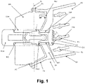
- the present invention relates to an air diffuser, comprising a casing C that defines a passageway for the circulation of an air flow from an inlet opening A1 to an outlet opening A2 of the casing C, as indicated in Figures 1 and 2 .
- the air diffuser further comprises a series of movable slats of a first type, including a movable driving slat LVa and movable driven slats LVb, which are configured and arranged in the casing C to move between a plurality of first positions, to control the direction of the air flow according to a first direction, in this case a horizontal direction, since for the illustrated exemplary embodiment the slats LVa, LVb run vertically (in a mounting situation of the air diffuser).
- a first direction in this case a horizontal direction
- the movable driven slats of a first type LVb are kinematically coupled to the movable driven slat of a first type LVa to move jointly between respective pluralities of first positions, that is, in a coordinated movement between the movable slats of a first type, all the slats of a first type being preferably arranged parallel to each other in any of the plurality of first positions.
- the movable slats of a first type both the driving LVa and the driven LVb, are hingedly fixed to a perimeter wall of a front section Ca of the casing C through respective first hinge axes Ev, parallel to each other, to rotate with respect thereto during the movement thereof between the respective pluralities of first positions, carrying out the kinematic connection mentioned in the previous paragraph by means of a transfer mechanism Rev, which has been partially illustrated in Figures 1 and 3 , which is not described in greater detail in the present document because it is of a conventional type, in order not to obscure the description of the truly novel elements of the present invention.
- the hinged fixing of the movable slats of a first type, both the driving LVa and the driven LVb is carried out through the insertion in respective holes of the front section Ca, of respective pins Pv that extend from opposite ends of each slat LVa, LVb, as shown in Figure 1 for the driving slat LVa (although for the driven slats LVb the situation is the same).
- the air diffuser of the present invention further comprises a series of movable slats of a second type, including a movable driving slat LHa and movable driven slats LHb, which are configured and arranged in the casing C to move between a plurality of second positions, to control the direction of the air flow according to a second direction, in this case a vertical direction, since for the illustrated exemplary embodiment the slats LHa, LHb run horizontally (in a mounting situation of the air diffuser).
- a second direction in this case a vertical direction
- the movable driven slats of a second type LHb are kinematically coupled to the movable driven slat of a second type LHa to move jointly between respective pluralities of second positions, that is, in a coordinated movement between the movable slats of a second type, all the slats of a second type being preferably arranged parallel to each other in any of the plurality of second positions.
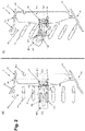
- the movable slats of a second type both the driving LHa and the driven LHb slats, are hingedly fixed to a perimeter wall of a rear section Cp of the casing C, in fluid communication with the front section Ca, through respective second hinge axes Eh, parallel to each other, to rotate with respect thereto during the movement thereof between the respective pluralities of second positions, carrying out the kinematic connection mentioned in the previous paragraph by means of a transfer mechanism Reh, which has been partially illustrated in Figure 2 , and which is also not described in greater detail herein for the same reasons stated above with respect to the transfer mechanism Rev.
- the hinged fixation of the movable slats of a second type, both the driving LHa and the driven LHb, is carried out through the insertion in respective holes of the rear section Cp, of respective pins Ph that extend from opposite ends of each slat LHa, LHb, as shown in Figure 2 for the driving slat LHa (although for the driven slats LHb the situation is the same).
- front section Ca of the casing C is understood as the portion of the casing C closest to the outlet opening A2.
- rear section Cp of the casing C is understood as the portion of the casing C closest to the inlet opening A1.
- Both front Ca and rear Cp sections are in fluid communication, enabling the air flow to run from the inlet opening A1 to the outlet opening A2.
- the movable slats of a second type LHa, LHb are also configured and arranged to regulate the air flow rate when moving between the pluralities of second positions, which include a closing position wherein the slats LHa, LHb partially overlap (position not illustrated), thus closing the passageway for the circulation of the air flow, thus blocking the passage of the air flow towards the outlet opening A2 of the casing C.
- the pluralities of second positions also include positions for which the airflow rate is larger and positions for which it is smaller, that is, the movable slats of a second type LHa, LHb rotate sufficiently, and are relatively dimensioned and arranged one in relation to the other, so as to interfere to a greater or lesser extent with the air flow, that is, to close the passage of the air flow towards the outlet opening A2 of the casing C more or less, or completely.
- the air diffuser of the present invention comprises a single actuator element M, or single-lever, kinematically and operatively connected to the movable slats of a first type LVa, LVb and to the movable slats of a second type LHa, LHb, to independently control the movements thereof between the pluralities of first and second positions, respectively.
- the single actuator element M comprises a first portion M1 mechanically connected to the movable driving slat of a first type LVa, and a second portion M2 mechanically connected to the movable driving slat of a second type LHa.
- the first portion M1 comprises a first end M1a, or grip end, to be grasped by a user to move the first portion M1 and the movable driving slat of a first type Lva with it, causing it to rotate with respect to the respective first hinge axis Ev thereof, and, by means of the transfer mechanism Rev, also causing the driven slats of a first type LVb to rotate in the same way about the respective first hinge axes Ev thereof, as can be seen when comparing views a) and b) of Figure 2 , which respectively represent a neutral position of all the slats LVa, LVb (i.e., a position for which they have not been rotated) and a position wherein the slats LVa, LVb have been rotated by a certain angle about the first hinge axes Ev.
- the first portion M1 of the actuator element M is directly connected to the movable driving slat of a first type LVa with freedom of rotation with respect to a first rotation axis Eo1 (see Figure 2 ), which is orthogonal to the first hinge axes Ev.
- first hinge axes Ev only have one degree of freedom with respect to the casing C, only enabling the rotational movement of the slats of a first type LVa, LVb.
- the first rotation axis Eo1 has two degrees of freedom with respect to the casing C, the one corresponding to the aforementioned rotation of the first portion M1 and, in addition, the one related to a movement that is integral to the movement of the slats of a first type LVa, LVb between the plurality of first positions.
- the first rotation axis Eo1 would be comprised in a plane perpendicular to the first hinge axes Ev.
- a first end M2a of the second portion M2 of the actuator element M is kinematically connected to a second end M1b of the first portion M1, opposite the grip end M1a, such that when a user grasps the grip end M1a of the first portion M1 of the actuator element M and causes it to rotate with respect to the first rotation axis Eo1, the second portion M2 of the actuator element M also rotates with respect to a second rotation axis Eo2 (see Figure 2 ) which is orthogonal to the second hinge axes Eh.
- Figures 1 to 3 show how the movable driving slat of a first type LVa comprises a tubular element Lvat and the first portion M1 of the actuator element M comprises a tubular segment M1t with an outer diameter smaller than the inner diameter of the tubular element Lvat, and wherein the tubular segment M1t is inserted and coupled with freedom of rotation in the tubular element Lvat, to rotate with respect to the first rotation axis Eo1, providing the aforementioned direct connection to the movable driving slat of a first type LVa.
- Such coupling is produced, for the illustrated exemplary embodiment, by deformation and elastic recovery of the tubular segment M1t when it is inserted into the tubular element Lvat, and when it overcomes, at the end of the insertion, respective tabs Pm1 (see Figure 2 ) and abuts against the edge of one of the ends of the tubular segment M1t.
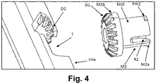
- a second end M2b, opposite the first end M2a, of the second portion M2 of the actuator element M is mechanically connected to the movable driving slat of a second type LHa through a gear coupling, comprising a first circular toothed gear D1 defined at the second end M2b of the second portion M2 of the actuator element M and a second circular toothed gear D2, mechanically coupled to the first circular toothed gear D1, which is defined in a region of the movable driving slat of a second type LHa, configured and arranged so that when rotating the second portion M2 of the actuator element M with respect to the second rotation axis Eo2, the movable driving slat of a second type LHa also rotates with respect to the respective second hinge axis Eh thereof, and, by means of the transfer mechanism Reh, also causing the driven slats of a second type Lhb to rotate
- Figures 3 and 4 show how, for the illustrated exemplary embodiment, the gear coupling is a bevel gear coupling, wherein the first circular toothed gear D1 is a bevel toothed wheel and the second circular toothed gear D2 is a bevel toothed wheel section, and the region of the movable driving slat of a second type Lha mentioned in the preceding paragraph is located adjacent to an indentation T defined on one side of the movable driving slat of a second type LHc, the indentation T being configured so that the bevel toothed wheel D1 is arranged with freedom of rotation therein, meshed with the bevel toothed wheel D2 section.
- the second portion M2 of the actuator element M is connected with freedom of rotation to a structural element Ce of the casing C arranged between the front Ca and rear Cp sections, to rotate with respect to the second rotation axis Eo2.
- Said structural element Ce is connected to the opposite walls of the casing C by means of arms.
- Said structural element Ce comprises such a structure as to minimise the resistance of the air flow running between the inlet opening A1 and the outlet opening A2.
- Such structural element Ce comprises a tubular member Cet and the second portion M2 of the actuator element M comprises a tubular segment M2t with an outer diameter smaller than the inner diameter of the tubular member Cet, and the tubular segment M2t is inserted and coupled with freedom of rotation in the tubular member Cet, to rotate with respect to the second rotation axis Eo2 (see Figure 2 ).
- Such coupling is produced, for the illustrated exemplary embodiment, by deformation and elastic recovery of the tubular segment M2t when it is inserted into the tubular member Cet, and when it overcomes, at the end of the insertion, respective tabs Pm2 (see Figure 1 ) and abuts against the edge of one of the ends of the tubular member Cet.
- the air diffuser of the present invention comprises a coupling element that hingedly connects the first portion M1 with the second portion M2 of the actuator element M.
- such a coupling element and part of the first M1 and second M2 portions of the actuator element M implement a constant-velocity joint, in particular it is a simple universal joint J, as indicated in Figures 1 and 2 by means of a rectangle of dashed lines within which the elements that form the simple universal joint J are included.
- the coupling element is a transmission shaft B, at the ends of which it has respective hinges that connect the transmission shaft with the first portion M1 and the second portion M2 of the actuator element M, respectively.
- Each of the hinges comprises a sphere Be1, Be2 and a bolt Bb1, Bb2 that crosses it and protrudes at both ends, the bolts Bb1, Bb2 running orthogonal to each other.
- the spheres Be1, Be2 are inserted in the tubular segments M1t, M2t of the first M1 and second M2 portions of the actuator element M and the bolts Bb1, Bb2 are guided in respective grooves R1, R2 defined in the tubular walls thereof, as can be seen in Figure 3 , wherein there are two grooves R1 and they are arranged at 180° with respect to each other around the tubular wall of the tubular segment M1t, and the same happens with the grooves R2 but with respect to the tubular segment M2t.
- rotation in all directions at both ends of the transmission shaft B and the linear movement thereof are enabled, and thus the movements of the slats LVa, LVb, LHa, LHb described above.
Landscapes
- Physics & Mathematics (AREA)
- Nonlinear Science (AREA)
- Engineering & Computer Science (AREA)
- Mechanical Engineering (AREA)
- General Physics & Mathematics (AREA)
- Optics & Photonics (AREA)
- Thermal Sciences (AREA)
- Chemical & Material Sciences (AREA)
- Crystallography & Structural Chemistry (AREA)
- Combustion & Propulsion (AREA)
- General Engineering & Computer Science (AREA)
- Air-Flow Control Members (AREA)
Applications Claiming Priority (1)
| Application Number | Priority Date | Filing Date | Title |
|---|---|---|---|
| ES202130132A ES2921600B2 (es) | 2021-02-18 | 2021-02-18 | Difusor de aire |
Publications (1)
| Publication Number | Publication Date |
|---|---|
| EP4046837A1 true EP4046837A1 (de) | 2022-08-24 |
Family
ID=82116068
Family Applications (1)
| Application Number | Title | Priority Date | Filing Date |
|---|---|---|---|
| EP22155239.1A Withdrawn EP4046837A1 (de) | 2021-02-18 | 2022-02-04 | Luftdiffusor |
Country Status (2)
| Country | Link |
|---|---|
| EP (1) | EP4046837A1 (de) |
| ES (1) | ES2921600B2 (de) |
Citations (4)
| Publication number | Priority date | Publication date | Assignee | Title |
|---|---|---|---|---|
| EP1207062B1 (de) | 2000-11-20 | 2010-08-11 | TRW Automotive Electronics & Components GmbH | Luftaustritt für Belüftungsanlagen |
| DE202012100243U1 (de) * | 2012-01-24 | 2012-03-16 | Dr. Schneider Kunststoffwerke Gmbh | Einrichtung zum Steuern eines Luftstroms |
| WO2016180813A1 (de) * | 2015-05-11 | 2016-11-17 | Dr. Schneider Kunststoffwerke Gmbh | Einrichtung zum steuern eines luftstroms |
| DE102016013353A1 (de) * | 2016-11-09 | 2018-05-09 | Audi Ag | Ausströmer für ein Kraftfahrzeug und zugehöriges Kraftfahrzeug |
Family Cites Families (4)
| Publication number | Priority date | Publication date | Assignee | Title |
|---|---|---|---|---|
| FR2645628B1 (fr) * | 1989-04-06 | 1994-08-05 | Bourbon Ind | Aerateur |
| DE19701499C1 (de) * | 1997-01-17 | 1997-12-11 | Daimler Benz Ag | Belüftungsdüse für Fahrzeuge |
| DE102015118548B4 (de) * | 2015-05-28 | 2017-05-04 | Dr. Schneider Kunststoffwerke Gmbh | Luftausströmer mit einer Steuereinrichtung |
| JP6579002B2 (ja) * | 2016-03-10 | 2019-09-25 | 豊田合成株式会社 | 空調用レジスタ |
-
2021
- 2021-02-18 ES ES202130132A patent/ES2921600B2/es active Active
-
2022
- 2022-02-04 EP EP22155239.1A patent/EP4046837A1/de not_active Withdrawn
Patent Citations (4)
| Publication number | Priority date | Publication date | Assignee | Title |
|---|---|---|---|---|
| EP1207062B1 (de) | 2000-11-20 | 2010-08-11 | TRW Automotive Electronics & Components GmbH | Luftaustritt für Belüftungsanlagen |
| DE202012100243U1 (de) * | 2012-01-24 | 2012-03-16 | Dr. Schneider Kunststoffwerke Gmbh | Einrichtung zum Steuern eines Luftstroms |
| WO2016180813A1 (de) * | 2015-05-11 | 2016-11-17 | Dr. Schneider Kunststoffwerke Gmbh | Einrichtung zum steuern eines luftstroms |
| DE102016013353A1 (de) * | 2016-11-09 | 2018-05-09 | Audi Ag | Ausströmer für ein Kraftfahrzeug und zugehöriges Kraftfahrzeug |
Also Published As
| Publication number | Publication date |
|---|---|
| ES2921600A1 (es) | 2022-08-30 |
| ES2921600B2 (es) | 2023-02-27 |
Similar Documents
| Publication | Publication Date | Title |
|---|---|---|
| CN106195418B (zh) | 风门装置 | |
| EP4011673B1 (de) | Aktive luftklappenvorrichtung für fahrzeug | |
| US5836814A (en) | Damper blade system | |
| US9889735B2 (en) | Active grill shutter actuation system | |
| EP3647092B1 (de) | Luftausströmer mit einem verstellmechanismus | |
| WO2007142957A2 (en) | Gear drive damper | |
| CN115805803A (zh) | 用于车辆的主动空气风门 | |
| DE102013100534B4 (de) | Einrichtung zum Steuern eines Luftstroms | |
| EP1816016B1 (de) | Luftverteileinheit für ein Fahrzeug | |
| JP7700387B2 (ja) | アクティブ吸気グリル及び車両 | |
| EP4279302B1 (de) | Fahrzeug mit einer luftauslassanordnung | |
| KR200489979Y1 (ko) | 공조장치용 디퓨져 | |
| JP6764258B2 (ja) | ダンパ装置 | |
| AU2018367564B2 (en) | Indoor unit of air conditioner | |
| KR20140021685A (ko) | 힌지 장치 | |
| EP2018986B1 (de) | Luftdüse für Kraftfahrzeuge | |
| ES2921600B2 (es) | Difusor de aire | |
| CN204901969U (zh) | 空调柜机导向装置及贯流空调柜机 | |
| CN105953392B (zh) | 全热交换器及其风门机构 | |
| CN112361572A (zh) | 导风板组件及空调机组 | |
| KR102693389B1 (ko) | 유량 조절이 가능한 디퓨저 | |
| CN111731078A (zh) | 一种出风口 | |
| EP2147810B1 (de) | Stellklappenaktuator sowie Stellklappenbaugruppe einer Heizungs-Lüftungseinheit | |
| EP4168698B1 (de) | Energierückgewinnungsventilsystem mit kugelsegmentventil zur steuerung des flüssigkeitsstroms in einer leitung | |
| KR100667275B1 (ko) | 공기조화기 |
Legal Events
| Date | Code | Title | Description |
|---|---|---|---|
| PUAI | Public reference made under article 153(3) epc to a published international application that has entered the european phase |
Free format text: ORIGINAL CODE: 0009012 |
|
| STAA | Information on the status of an ep patent application or granted ep patent |
Free format text: STATUS: THE APPLICATION HAS BEEN PUBLISHED |
|
| AK | Designated contracting states |
Kind code of ref document: A1 Designated state(s): AL AT BE BG CH CY CZ DE DK EE ES FI FR GB GR HR HU IE IS IT LI LT LU LV MC MK MT NL NO PL PT RO RS SE SI SK SM TR |
|
| P01 | Opt-out of the competence of the unified patent court (upc) registered |
Effective date: 20230526 |
|
| STAA | Information on the status of an ep patent application or granted ep patent |
Free format text: STATUS: THE APPLICATION IS DEEMED TO BE WITHDRAWN |
|
| 18D | Application deemed to be withdrawn |
Effective date: 20230225 |