EP4046834A1 - Véhicule à traction électrique ou hybride équipé d'un système de climatisation, avec récupération de chaleur par refroidissement de composants électriques et/ou électroniques - Google Patents
Véhicule à traction électrique ou hybride équipé d'un système de climatisation, avec récupération de chaleur par refroidissement de composants électriques et/ou électroniques Download PDFInfo
- Publication number
- EP4046834A1 EP4046834A1 EP22157488.2A EP22157488A EP4046834A1 EP 4046834 A1 EP4046834 A1 EP 4046834A1 EP 22157488 A EP22157488 A EP 22157488A EP 4046834 A1 EP4046834 A1 EP 4046834A1
- Authority
- EP
- European Patent Office
- Prior art keywords
- exchanger
- heat
- air
- control unit
- passenger compartment
- Prior art date
- Legal status (The legal status is an assumption and is not a legal conclusion. Google has not performed a legal analysis and makes no representation as to the accuracy of the status listed.)
- Granted
Links
Images


Classifications
-
- B—PERFORMING OPERATIONS; TRANSPORTING
- B60—VEHICLES IN GENERAL
- B60H—ARRANGEMENTS OF HEATING, COOLING, VENTILATING OR OTHER AIR-TREATING DEVICES SPECIALLY ADAPTED FOR PASSENGER OR GOODS SPACES OF VEHICLES
- B60H1/00—Heating, cooling or ventilating devices
- B60H1/00357—Air-conditioning arrangements specially adapted for particular vehicles
- B60H1/00371—Air-conditioning arrangements specially adapted for particular vehicles for vehicles carrying large numbers of passengers, e.g. buses
-
- B—PERFORMING OPERATIONS; TRANSPORTING
- B60—VEHICLES IN GENERAL
- B60H—ARRANGEMENTS OF HEATING, COOLING, VENTILATING OR OTHER AIR-TREATING DEVICES SPECIALLY ADAPTED FOR PASSENGER OR GOODS SPACES OF VEHICLES
- B60H1/00—Heating, cooling or ventilating devices
- B60H1/00271—HVAC devices specially adapted for particular vehicle parts or components and being connected to the vehicle HVAC unit
-
- B—PERFORMING OPERATIONS; TRANSPORTING
- B60—VEHICLES IN GENERAL
- B60H—ARRANGEMENTS OF HEATING, COOLING, VENTILATING OR OTHER AIR-TREATING DEVICES SPECIALLY ADAPTED FOR PASSENGER OR GOODS SPACES OF VEHICLES
- B60H1/00—Heating, cooling or ventilating devices
- B60H1/02—Heating, cooling or ventilating devices the heat being derived from the propulsion plant
- B60H1/14—Heating, cooling or ventilating devices the heat being derived from the propulsion plant other than from cooling liquid of the plant
- B60H1/143—Heating, cooling or ventilating devices the heat being derived from the propulsion plant other than from cooling liquid of the plant the heat being derived from cooling an electric component, e.g. electric motors, electric circuits, fuel cells or batteries
-
- B—PERFORMING OPERATIONS; TRANSPORTING
- B61—RAILWAYS
- B61D—BODY DETAILS OR KINDS OF RAILWAY VEHICLES
- B61D1/00—Carriages for ordinary railway passenger traffic
-
- B—PERFORMING OPERATIONS; TRANSPORTING
- B61—RAILWAYS
- B61D—BODY DETAILS OR KINDS OF RAILWAY VEHICLES
- B61D27/00—Heating, cooling, ventilating, or air-conditioning
- B61D27/0018—Air-conditioning means, i.e. combining at least two of the following ways of treating or supplying air, namely heating, cooling or ventilating
-
- B—PERFORMING OPERATIONS; TRANSPORTING
- B60—VEHICLES IN GENERAL
- B60H—ARRANGEMENTS OF HEATING, COOLING, VENTILATING OR OTHER AIR-TREATING DEVICES SPECIALLY ADAPTED FOR PASSENGER OR GOODS SPACES OF VEHICLES
- B60H1/00—Heating, cooling or ventilating devices
- B60H1/00271—HVAC devices specially adapted for particular vehicle parts or components and being connected to the vehicle HVAC unit
- B60H2001/00307—Component temperature regulation using a liquid flow
Definitions
- the present invention refers to an electric traction or to a hybrid traction vehicle, provided with an air conditioning system, for conditioning a passenger compartment of the vehicle.
- the present invention refers to a railway vehicle, for example to a train, without losing generality since it may also be applied to road vehicles, naval vehicles, etc...
- the fan conveys external air, or recirculated air from the passenger compartment, or an adjustable mixture of external air and recirculated air, to a heating unit supplied with a thermal exchange fluid which removes heat from the converter device.
- US10315493B2 illustrates a vehicle according to the preamble of claim 1, wherein a three-way regulating valve receives a coolant coming from a heat source, recovered from electrical components. Such valve is controlled for splitting the coolant between two circuit branches, in parallel to one another, having respective heat exchangers: one of such exchangers heats air sent into the passenger compartment, whereas the other one is cooled by external air.
- This solution requires a tank for mixing the parts of coolant which flow in the two circuit branches, before returning to the heat source.
- the object of the present invention is to manufacture an electric or hybrid traction vehicle provided with an air conditioning system, with heat recovery from the cooling of electrical and/or electronic components, which allows for satisfying in a simple and cost-effective manner the above-described needs and which perfects the solution shown in US10315493B2 .
- an electric or hybrid traction vehicle is provided, as defined in the appended claims.
- reference numeral 1 indicates a vehicle, defined in the specific case by a passenger car of a train. More in general, the present invention applies not only to trains, but to any electric traction vehicle, or to any hybrid traction vehicle (for example, ships, buses, etc.) with an electric drive coupled to another traction source.
- the passenger car 1 is, in particular, a head passenger car of the train and comprises an electric drive 2, having at least one electric motor or an electric motor-generator (not illustrated) for mechanically operating the wheels 4 of at least one truck 5, which is provided underneath a floor of the passenger car 1.
- the vehicle 1 has electronic and/or electrical components which require cooling, generally indicated by reference numeral 8 in Figure 1 .
- the electrical/electronic components 8, in the specific case illustrated, are defined by power electronic converters 10, for converting, transforming and/or transferring electric energy for the motor or motor-generator.
- the electric drive 2 is of known type, therefore it is not described in detail.
- the power electronic converters 10 such as for example inverters (schematized in Figure 2 ), receive electric energy from a catenary or from an electrified line installed on the ground or from another source (not illustrated) and transform the electric energy so as to operate one or more electric motors for towing the vehicle 1.
- the power electronic converters 10 are arranged on a roof or deck 9 of the passenger car 1 ( Figure 1 ).
- the passenger car 1 in combination with or in alternative to the drawing of electric energy from a catenary or from a ground electrified line, the passenger car 1 comprises an autonomous electric energy source defined by a battery (not illustrated), which is connected to the power electronic converters 10 for feeding, and preferably also receiving and stocking, electric current in direct current.
- a battery not illustrated
- the passenger car 1 comprises at least one passenger compartment 11 accessible by passengers, driver, operators, etc., through one or more doors.
- the passenger compartment 11 is conditioned for satisfying the needs of air quality and of thermal or thermo-hygrometric comfort during the journeys.
- the passenger compartment 11 has air temperature conditions and, in summer, also relative humidity conditions that can be adjusted by means of an air conditioning system 15, schematically illustrated in Figure 2 .
- the air conditioning system 15 comprises a control unit 16 and a plurality of sensors (of known type and not illustrated), arranged inside the passenger compartment 11 and/or at the external atmosphere and/or at ducts/exchangers/devices of the system 15 for sending, to the control unit 16, signals indicative of the conditions/properties of the air outside and inside the passenger compartment 11 (for example: temperature, relative humidity, flow rate, concentration of carbon dioxide, etc.) and conditions/properties of the used thermal exchange fluids (for example: temperature, pressure, flow rate, etc.).
- signals indicative of the conditions/properties of the air outside and inside the passenger compartment 11 for example: temperature, relative humidity, flow rate, concentration of carbon dioxide, etc.
- conditions/properties of the used thermal exchange fluids for example: temperature, pressure, flow rate, etc.
- the control unit 16 is configured, by means of control algorithms (in open loop or preferably in closed loop), to adjust the thermal exchanges in the air conditioning system 15 in order to achieve:
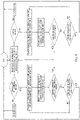
- the system 15 comprises an aeraulic duct 20 which, in use, conveys a forced air flow into the passenger compartment 11. Such flow is obtained through the action of at least one fan 21.
- the duct 20 is provided, at an outlet 22 that leads to the passenger compartment 11, with a plurality of blowers or diffusers 23 arranged in positions spaced from one another (in Figure 2 , for the sake of simplicity, only one of the diffusers 23 is shown).
- the system 15 preferably comprises a mixer 24 of known type, arranged at an initial length of the duct 20 and communicating, by means of respective inlets, 25 and 26, with the outer environment and with the passenger compartment 11 so as to be able to mix an external air flow with an air flow coming from the passenger compartment 11.
- the adjustment of the mixing is controlled by the control unit 16 in a known manner and not described in detail, for example by choking the opening of the inlets 25 and 26.
- the fan 21 constitutes part of the mixer 24, but it could also be provided in the duct 20 downstream of the mixer 24 (considering the forward direction of the air); or two fans could be provided, one for the air sucked through the inlet 25, and the other one for the air sucked through the inlet 26.
- the system 15 further comprises two heat exchangers, 27 and 28, respectively called “cold battery” and “hot battery”, arranged one after the other along the duct 20, downstream of the mixer 24.
- the exchanger 27, arranged between the mixer 24 and the exchanger 28, is provided for cooling and dehumidifying the air flow in the duct 20, and in particular defines the evaporator of a refrigerating assembly 30.
- the latter if of the steam compression type, in general comprises a circuit 31 in which a refrigerant fluid flows; a compressor 32; a heat exchanger 33 (condenser); a lamination valve 34.
- the exchanger 28 constitutes part of a waste heat dissipation and recovery system 35 produced by the power electronic converters 10.
- the system 35 it will be possible to apply the system 35 to electronic/electrical components 8 which are different from the power electronic converters 10 indicated herein by way of example, but which require to be cooled during the relative operation.
- the system 35 comprises a circuit 36, in which a thermal exchange fluid flows (for example liquid water), and a circulation pump 37.
- a thermal exchange fluid flows (for example liquid water)
- a circulation pump 37 for example
- the exchanger 28 which acts as "hot battery” for heating or post-heating the treated air, is an additional component with respect to the traditional system layouts that do not provide for heat recovery from electrical/electronic components 8, whereas such recovery in the present invention is obtained by means of the system 35.
- the system 35 further comprises at least one heat exchanger 38 arranged along the circuit 36 for removing heat from the electrical/electronic components 8, heat which will then be recovered and transferred through the exchanger 28 to the air flow to be heated in the duct 20.
- the exchanger 38 removes heat from the power electronic converters 10, but as abovementioned it could remove heat from other types of electrical/electronic components 8 which naturally tend to heat up during their normal use and thus require cooling. For example, heat could be removed from an electrical battery, if provided.
- the set of the exchanger 38 and the power electronic converter 10 (or, more in general, the set of the exchanger 38 and the electrical/electronic component 8) forms one single apparatus.
- the fact of recovering the heat which is produced by at least one electrical and/or electronic component allows for reducing the energy consumptions necessary for heating, in the cold or winter period, the air flow conveyed from the duct 20 towards the passenger compartment 11.
- a better air quality and a better comfort of the occupants is instead obtained through the control of the relative humidity in the passenger compartment 11 (otherwise not obtained in traditional system layouts).
- the performances and the operating conditions of the power electronic converters 10 improve, thanks to a more effective removal of the heat to be dissipated in the case of the system 35 proposed according to the present invention.
- the position of the exchanger 38 is determined by the layout provided on the vehicle for the power electronic converters 10 and/or for any other electrical/electronic components 8 that are cooled by the exchangers 38 of the system 35.
- the apparatuses comprising the exchangers 38 are arranged on the roof or deck 9 ( Figure 1 ) .
- the system 35 further comprises a radiator 39 arranged along the circuit 36, and passed through, in use, by external air, which preferably is forcedly made to circulate by means of at least one fan 40, in order to discharge the part of heat which is in excess, i.e. the part of heat which is produced by the power electronic converters 10 but which is not used for heating the air in the duct 20.
- radiator 39 and the fan 40 thereof are arranged on the roof or deck 9 ( Figure 1 ).
- the system 35 comprises a bypass pipe 41, in parallel to the exchanger 28, and a three-way regulating valve 42, arranged along the circuit 36 at one of the two points of intersection between the pipe 41 and the circuit branch where the exchanger 28 is arranged.
- the valve 42 is arranged in the point of intersection downstream of the exchanger 28 and of the pipe 41 (the term "downstream" is determined by the direction of the flow, which in turn is determined by the pump 37).
- the valve 42 is electrically actuated under the command of the control unit 16.
- valve 42 the heat removed through the exchangers 38 can be partially or totally directed towards the exchanger 28, by splitting the heat transfer fluid flow rate between the exchanger 28 and the pipe 41, depending on the thermal exchanges required, on the basis of the algorithms implemented in the control unit 16. It should be noted that the valve 42, as well as the exchanger 28, are additional components with respect to the traditional system layouts devoid of heat recovery.
- the radiator 39 is arranged in series, downstream with respect to the pipe 41 and to the exchanger 28, and upstream with respect to the exchangers 38. Therefore, the heat transfer liquid flow rate in the pipe 41 joins with the one that flows through the exchanger 28, at the downstream point of intersection (where the valve 42 is arranged, in the specific example illustrated), and the entire flow rate flows towards the radiator 39. Thanks to the positioning in series of the radiator 39, the thermal exchange is adjusted in a relatively simple manner, in order to obtain the suitable temperature entering the exchangers 38. Furthermore, the arrangement of the circuit according to the present invention does not require any tank for mixing the two parts of liquid coming from the exchanger 28 and from the pipe 41.
- the fluid flow rate always flows through the radiator 39, which is never excluded from the circuit, before arriving at the exchangers 38.
- the radiator 39 can be bypassed: in fact, the circuit 36 comprises a bypass line 41a, in parallel to the radiator 39, and a three-way regulating valve 43 controlled by the control unit 16 so as to vary the heat removed from the radiator 39 and thus the temperature entering the exchangers 38, by splitting the heat transfer liquid flow rate between the radiator 39 and the line 41a.
- control unit 16 simultaneously adjusts the system 35 and the refrigerating assembly 30, also in the summer period, so as to achieve the temperature setpoint (Tset) and the air relative humidity setpoint (RHset) in the passenger compartment 11.
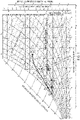
- the temperature setpoint is represented, for example, by the abscissa value of points I and I' in Figure 3 , wherein the transformations to which the treated air is subjected are shown in a Mollier psychrometric diagram for the humid air.
- the temperature setpoint is of about 25 °C, but it could possibly be different (typically, the temperature and humidity setpoints can be freely chosen so as to be within the area highlighted in Figure 3 , which corresponds to thermo-hygrometric wellness conditions of the occupants, and also to air quality conditions inside the passenger compartment).
- the treated air, flowing along the duct 20, through the exchanger 27 up to the passenger compartment 11, is introduced in the environment in the conditions identified by point A in the diagram of Figure 3 .
- the control unit 16 adjusts the refrigerating assembly 30 in such a manner that the heat removed by means of the exchanger 27 is greater than the heat that would be theoretically removed leaving the exchanger 28 switched off.
- control unit 16 adjusts the system 35 (by means of the valve 42) in such a manner that the exchanger 28 transfers the heat removed from the electrical/electronic components 8 to the air flow in the duct 20 for achieving, inside the passenger compartment 11, besides the temperature setpoint, also an environment humidity value that can ensure at the same time suitable levels of hygrometric comfort and of air quality.
- This control mode is identified, in the example of Figure 3 , by the achievement of point A' through the cooling and the dehumidifying obtained by means of the exchanger 27, and then by a horizontal stretch (from point A' to point B) defining the post-heating obtained by means of the exchanger 28.
- the air inside the passenger compartment 11 achieves the desired air quality and thermo-hygrometric wellness conditions, identified by point I (which respects the temperature and relative humidity setpoints and the maximum limit of environment specific humidity, respectively equal to 25°C, 50% and 10.5 g v /kg a ).
- control unit 16 is configured by means of the implementation of suitable algorithms to achieve, besides the temperature setpoint, also the environment relative humidity setpoint.
- the optimum control strategy for controlling, in a coordinated or combined manner, the refrigerating assembly 30 and the valve 42 can vary depending on the considered case (on the basis of the machines used, the setpoints, etc%): the control strategy to be used will thus be defined each time, on the basis of the specificities of the case.
- the speed of the fan 40 is adjusted by the control unit 16, or by another control unit on board the vehicle, so as to increase (at discrete paces, or progressively) upon the increase in the forward speed of the vehicle, thus correlating the air flow rate (and thus the cooling caused by the radiator 39) indirectly to the quantity of energy dissipated by the power electronic converters 10.
- the forward speed of the train can be detected by means of one or more speed sensors arranged on board, or can be estimated starting from other quantities measured on board and possibly on the ground, or can be determined remotely and wirelessly transmitted to the vehicle, or could be determined by means of a geolocation system.
- the speed adjustment of the fan 40 allows for removing less or more heat from the radiator 39 in proportion to how much the power electronic converters 10 dissipate, and to the compatibility with the noise level limits (in the absence of the adjustment of the fan 40, the temperature of the liquid would oscillate according to the performance of the power dissipated by the power electronic converters 10).
- the rotation speed of the fan 40 is adjusted so as to assume two different values depending on the forward speed of the vehicle: a lower rotation speed for forward speeds that are null and/or below a preestablished threshold (given the possible stringent noise limits and the reduced powers to be dissipated); whereas, a higher rotation speed when the forward speed is above said threshold.
- control strategy provides for the following operations.
- the control unit 16 first reduces the speed of the fan 40 so as to reduce the heat removed and thus increase the temperature of the heat transfer fluid upstream and downstream of the exchangers 38 (compatibly with the technological limits required by the power electronic converters 10).
- the control unit 16 starts intervening on the valve 43 so as to reduce the heat transfer fluid flow rate to the radiator 39 and deviate it along the line 41a, up to the complete bypass of the radiator 39 if necessary. In this manner, the heat removed from the radiator 39 is further reduced, hence the temperature of the heat transfer fluid to the exchangers 38 still increases, in order to make greater heat available at the exchanger 28 (as long as this increase is compatible with the maximum temperature admitted to the power electronic converters 10: in negative case, the valve 43 and/or the fan 40 are not adjusted).
- the temperature of the heat transfer fluid is controlled by the control unit 16 by means of suitable temperature probes to be installed at the entrance and at the exit of the set of exchangers 38.
- the radiator 39 can be replaced by a liquid/liquid heat exchanger.
- the cooling can be carried out by means of sea/lake/river water.
- the adjustment for discharging the residual thermal load of the electrical/electronic components 8 is obtained by varying the speed of a pump that feeds the abovementioned exchanger with the sea/lake/river water (in a manner similar to the adjustment of the fan 40).
- the system 15 comprises an additional heating device 44, of known type and not described in detail, comprising one or more electric resistances 45, for example placed inside the passenger compartment.
- the device 44 is passed through by natural or forced convention by an air flow, so as to obtain, in the passenger compartment 11, the temperature setpoint in a relatively rapid timeframe during the winter period, when the vehicle is still and/or the power electronic converters 10 are not sufficiently hot for producing heat usable by the exchanger 28 of the system 35 in a sufficient quantity for heating the passenger compartment 11.
- the system 15 is managed by the control unit 16 so as to simultaneously control the thermal exchange in the exchangers 27 and 28, in order to achieve not only the temperature setpoint (Tset), but also the relative humidity setpoint (RHset) during the summer season only.
- Tset temperature setpoint
- RHset relative humidity setpoint
- the air coming out of the exchanger 27 is in conditions near those of saturation. Consequently, in order to maintain the correct environment hygrometric conditions (RHset), upon the varying of the external relative humidity, the temperature of the air exiting the exchanger 27 has to be maintained constant at the value of point A' ( Figure 3 ).
- This can be obtained in feedback by means of a temperature sensor, of known type, placed downstream of the exchanger 27, which communicates the temperature value detected at the control unit 16.
- the control unit 16 thus adjusts the cooling system 30.
- the temperature setpoint (Tset) is ensured thanks to a temperature sensor of known type alternatively placed in the passenger compartment 11 or in the suction duct of the inlet 26.
- control unit 16 Upon the decreasing (increasing) of the internal temperature of the air, the control unit 16 increases (decreases) the heat provided to the exchanger 28 adjusting the valve 42, and possibly the valve 43 and/or the fan 40. In a similar manner, during the winter season, upon the increasing (decreasing) of the environment temperature, the control unit 16 decreases (increases) the heat provided to the exchanger 28 adjusting the valve 42, and possibly the valve 43 and/or the fan 40.
- resistors 45 of the device 44 are used only as final possibility of intervention, preferring the heat recovery from the electrical/electronic components for heating the air in the passenger compartment.
- system 15 could be installed on road vehicles, and not on railway vehicles, or also on naval means with electric or hybrid propulsion.
- the device 44 could also be directly installed in the duct 20, downstream of the exchanger 28.
Landscapes
- Engineering & Computer Science (AREA)
- Mechanical Engineering (AREA)
- Physics & Mathematics (AREA)
- Thermal Sciences (AREA)
- Chemical & Material Sciences (AREA)
- Combustion & Propulsion (AREA)
- Transportation (AREA)
- Air-Conditioning For Vehicles (AREA)
- Cooling, Air Intake And Gas Exhaust, And Fuel Tank Arrangements In Propulsion Units (AREA)
Applications Claiming Priority (1)
| Application Number | Priority Date | Filing Date | Title |
|---|---|---|---|
| IT102021000003755A IT202100003755A1 (it) | 2021-02-18 | 2021-02-18 | Veicolo a trazione elettrica o ibrida dotato di un impianto di climatizzazione, con recupero di calore da raffreddamento di componenti elettrici e/o elettronici |
Publications (2)
| Publication Number | Publication Date |
|---|---|
| EP4046834A1 true EP4046834A1 (fr) | 2022-08-24 |
| EP4046834B1 EP4046834B1 (fr) | 2023-05-10 |
Family
ID=75660268
Family Applications (1)
| Application Number | Title | Priority Date | Filing Date |
|---|---|---|---|
| EP22157488.2A Active EP4046834B1 (fr) | 2021-02-18 | 2022-02-18 | Véhicule à traction électrique ou hybride équipé d'un système de climatisation, avec récupération de chaleur par refroidissement de composants électriques et/ou électroniques |
Country Status (3)
| Country | Link |
|---|---|
| EP (1) | EP4046834B1 (fr) |
| ES (1) | ES2951969T3 (fr) |
| IT (1) | IT202100003755A1 (fr) |
Cited By (2)
| Publication number | Priority date | Publication date | Assignee | Title |
|---|---|---|---|---|
| DE102023005262A1 (de) | 2023-01-25 | 2024-07-25 | Mercedes-Benz Group AG | System zur Kühlung eines Elektronikmoduls in einem Fahrzeug |
| US12466239B2 (en) | 2023-08-03 | 2025-11-11 | Hitachi Rail Sts S.P.A. | Electric or hybrid traction vehicle equipped with an air conditioning system, with heat recovery from cooling of electrical and/or electronic components |
Citations (6)
| Publication number | Priority date | Publication date | Assignee | Title |
|---|---|---|---|---|
| DE19914565A1 (de) | 1999-03-31 | 2000-10-05 | Abb Daimler Benz Transp | Einrichtung zur Kühlung von wärmeproduzierenden Baukomponenten eines elektrischen Schienenfahrzeugs |
| US7931209B2 (en) * | 2005-07-05 | 2011-04-26 | C.R.F. Societa Consortile Per Azioni | System for controlling an air-conditioning system within an environment, in particular the passenger compartment of a vehicle |
| US10315493B2 (en) | 2017-06-27 | 2019-06-11 | Hyundai Motor Company | HVAC system for a vehicle and method of use |
| EP3498513A1 (fr) * | 2017-12-18 | 2019-06-19 | Scania CV AB | Procédé et système de climatisation d'une batterie à propulsion et compartiment passagers d'un véhicule |
| US20190299738A1 (en) * | 2016-10-31 | 2019-10-03 | Williams Advanced Engineering Limited | Heating and cooling system for an electric vehicle |
| WO2020104278A1 (fr) * | 2018-11-21 | 2020-05-28 | Bombardier Transportation Gmbh | Véhicule avec un système de chauffage de plancher |
-
2021
- 2021-02-18 IT IT102021000003755A patent/IT202100003755A1/it unknown
-
2022
- 2022-02-18 EP EP22157488.2A patent/EP4046834B1/fr active Active
- 2022-02-18 ES ES22157488T patent/ES2951969T3/es active Active
Patent Citations (6)
| Publication number | Priority date | Publication date | Assignee | Title |
|---|---|---|---|---|
| DE19914565A1 (de) | 1999-03-31 | 2000-10-05 | Abb Daimler Benz Transp | Einrichtung zur Kühlung von wärmeproduzierenden Baukomponenten eines elektrischen Schienenfahrzeugs |
| US7931209B2 (en) * | 2005-07-05 | 2011-04-26 | C.R.F. Societa Consortile Per Azioni | System for controlling an air-conditioning system within an environment, in particular the passenger compartment of a vehicle |
| US20190299738A1 (en) * | 2016-10-31 | 2019-10-03 | Williams Advanced Engineering Limited | Heating and cooling system for an electric vehicle |
| US10315493B2 (en) | 2017-06-27 | 2019-06-11 | Hyundai Motor Company | HVAC system for a vehicle and method of use |
| EP3498513A1 (fr) * | 2017-12-18 | 2019-06-19 | Scania CV AB | Procédé et système de climatisation d'une batterie à propulsion et compartiment passagers d'un véhicule |
| WO2020104278A1 (fr) * | 2018-11-21 | 2020-05-28 | Bombardier Transportation Gmbh | Véhicule avec un système de chauffage de plancher |
Cited By (2)
| Publication number | Priority date | Publication date | Assignee | Title |
|---|---|---|---|---|
| DE102023005262A1 (de) | 2023-01-25 | 2024-07-25 | Mercedes-Benz Group AG | System zur Kühlung eines Elektronikmoduls in einem Fahrzeug |
| US12466239B2 (en) | 2023-08-03 | 2025-11-11 | Hitachi Rail Sts S.P.A. | Electric or hybrid traction vehicle equipped with an air conditioning system, with heat recovery from cooling of electrical and/or electronic components |
Also Published As
| Publication number | Publication date |
|---|---|
| EP4046834B1 (fr) | 2023-05-10 |
| IT202100003755A1 (it) | 2022-08-18 |
| ES2951969T3 (es) | 2023-10-26 |
Similar Documents
| Publication | Publication Date | Title |
|---|---|---|
| US5725048A (en) | Process for cooling drive components and heating the passenger compartment of a motor vehicle, especially an electrically driven vehicle, and arrangement for implementing the process | |
| US10414243B2 (en) | Vehicular ventilation module for use with a vehicular HVAC system | |
| CN103796853B (zh) | 包括旁路换热器的空气流动通道的暖通和/或空调设备 | |
| KR102266390B1 (ko) | 자동차 공조 시스템 및 공조 시스템을 작동시키기 위한 방법 | |
| US7975637B1 (en) | Temperature control system for a hybrid vehicle | |
| CN110194044A (zh) | 机动车的空调系统和用于运行空调系统的方法 | |
| CN111886148B (zh) | 车辆用空气调节装置 | |
| CN106965640A (zh) | 空调系统和将空气质量流导向空调系统中的空气引导设备 | |
| EP4046834B1 (fr) | Véhicule à traction électrique ou hybride équipé d'un système de climatisation, avec récupération de chaleur par refroidissement de composants électriques et/ou électroniques | |
| KR20120035014A (ko) | 자동차의 보조 냉난방장치 | |
| CN102371866A (zh) | 车辆用空气调节系统 | |
| CN103673257A (zh) | 汽车的用于吸热的换热器装置和空调系统 | |
| CN104781094B (zh) | 车辆空气调节器 | |
| JP2017106367A (ja) | 車両用冷却システム | |
| CN105313643A (zh) | 电气化车辆的热泵辅助发动机冷却 | |
| US12466239B2 (en) | Electric or hybrid traction vehicle equipped with an air conditioning system, with heat recovery from cooling of electrical and/or electronic components | |
| CN104114391A (zh) | 用作脉动电热除冰热泵的空气调节循环 | |
| CN112670615B (zh) | 用于能量储存装置的温度控制的装置 | |
| JP2022546954A (ja) | 車両内のバッテリーの温度及び室内空気調和装置の温度の統合的制御システム | |
| CN113525022B (zh) | 具有改进的空气处理的加热和/或空调设施及其方法 | |
| US20150323227A1 (en) | Heat system for compartment of a train car | |
| US20150321678A1 (en) | Heater for the passenger or driver compartment of a train car | |
| JP2020131846A (ja) | 車両用空気調和装置 | |
| CN115605362B (zh) | Hvac模块和包括这样的模块的hvac系统 | |
| CN111731064B (zh) | 具有空调器的车辆 |
Legal Events
| Date | Code | Title | Description |
|---|---|---|---|
| PUAI | Public reference made under article 153(3) epc to a published international application that has entered the european phase |
Free format text: ORIGINAL CODE: 0009012 |
|
| STAA | Information on the status of an ep patent application or granted ep patent |
Free format text: STATUS: THE APPLICATION HAS BEEN PUBLISHED |
|
| AK | Designated contracting states |
Kind code of ref document: A1 Designated state(s): AL AT BE BG CH CY CZ DE DK EE ES FI FR GB GR HR HU IE IS IT LI LT LU LV MC MK MT NL NO PL PT RO RS SE SI SK SM TR |
|
| STAA | Information on the status of an ep patent application or granted ep patent |
Free format text: STATUS: REQUEST FOR EXAMINATION WAS MADE |
|
| 17P | Request for examination filed |
Effective date: 20221125 |
|
| RBV | Designated contracting states (corrected) |
Designated state(s): AL AT BE BG CH CY CZ DE DK EE ES FI FR GB GR HR HU IE IS IT LI LT LU LV MC MK MT NL NO PL PT RO RS SE SI SK SM TR |
|
| GRAP | Despatch of communication of intention to grant a patent |
Free format text: ORIGINAL CODE: EPIDOSNIGR1 |
|
| STAA | Information on the status of an ep patent application or granted ep patent |
Free format text: STATUS: GRANT OF PATENT IS INTENDED |
|
| RIC1 | Information provided on ipc code assigned before grant |
Ipc: B61D 1/00 20060101ALI20230206BHEP Ipc: B60H 1/14 20060101ALI20230206BHEP Ipc: B61D 27/00 20060101ALI20230206BHEP Ipc: B60H 1/00 20060101AFI20230206BHEP |
|
| INTG | Intention to grant announced |
Effective date: 20230221 |
|
| GRAS | Grant fee paid |
Free format text: ORIGINAL CODE: EPIDOSNIGR3 |
|
| GRAA | (expected) grant |
Free format text: ORIGINAL CODE: 0009210 |
|
| STAA | Information on the status of an ep patent application or granted ep patent |
Free format text: STATUS: THE PATENT HAS BEEN GRANTED |
|
| AK | Designated contracting states |
Kind code of ref document: B1 Designated state(s): AL AT BE BG CH CY CZ DE DK EE ES FI FR GB GR HR HU IE IS IT LI LT LU LV MC MK MT NL NO PL PT RO RS SE SI SK SM TR |
|
| REG | Reference to a national code |
Ref country code: GB Ref legal event code: FG4D |
|
| REG | Reference to a national code |
Ref country code: AT Ref legal event code: REF Ref document number: 1566358 Country of ref document: AT Kind code of ref document: T Effective date: 20230515 Ref country code: CH Ref legal event code: EP |
|
| REG | Reference to a national code |
Ref country code: DE Ref legal event code: R096 Ref document number: 602022000071 Country of ref document: DE |
|
| REG | Reference to a national code |
Ref country code: IE Ref legal event code: FG4D |
|
| REG | Reference to a national code |
Ref country code: LT Ref legal event code: MG9D |
|
| REG | Reference to a national code |
Ref country code: NL Ref legal event code: MP Effective date: 20230510 |
|
| REG | Reference to a national code |
Ref country code: AT Ref legal event code: MK05 Ref document number: 1566358 Country of ref document: AT Kind code of ref document: T Effective date: 20230510 |
|
| REG | Reference to a national code |
Ref country code: ES Ref legal event code: FG2A Ref document number: 2951969 Country of ref document: ES Kind code of ref document: T3 Effective date: 20231026 |
|
| PG25 | Lapsed in a contracting state [announced via postgrant information from national office to epo] |
Ref country code: SE Free format text: LAPSE BECAUSE OF FAILURE TO SUBMIT A TRANSLATION OF THE DESCRIPTION OR TO PAY THE FEE WITHIN THE PRESCRIBED TIME-LIMIT Effective date: 20230510 Ref country code: PT Free format text: LAPSE BECAUSE OF FAILURE TO SUBMIT A TRANSLATION OF THE DESCRIPTION OR TO PAY THE FEE WITHIN THE PRESCRIBED TIME-LIMIT Effective date: 20230911 Ref country code: NO Free format text: LAPSE BECAUSE OF FAILURE TO SUBMIT A TRANSLATION OF THE DESCRIPTION OR TO PAY THE FEE WITHIN THE PRESCRIBED TIME-LIMIT Effective date: 20230810 Ref country code: NL Free format text: LAPSE BECAUSE OF FAILURE TO SUBMIT A TRANSLATION OF THE DESCRIPTION OR TO PAY THE FEE WITHIN THE PRESCRIBED TIME-LIMIT Effective date: 20230510 Ref country code: AT Free format text: LAPSE BECAUSE OF FAILURE TO SUBMIT A TRANSLATION OF THE DESCRIPTION OR TO PAY THE FEE WITHIN THE PRESCRIBED TIME-LIMIT Effective date: 20230510 |
|
| PG25 | Lapsed in a contracting state [announced via postgrant information from national office to epo] |
Ref country code: RS Free format text: LAPSE BECAUSE OF FAILURE TO SUBMIT A TRANSLATION OF THE DESCRIPTION OR TO PAY THE FEE WITHIN THE PRESCRIBED TIME-LIMIT Effective date: 20230510 Ref country code: PL Free format text: LAPSE BECAUSE OF FAILURE TO SUBMIT A TRANSLATION OF THE DESCRIPTION OR TO PAY THE FEE WITHIN THE PRESCRIBED TIME-LIMIT Effective date: 20230510 Ref country code: LV Free format text: LAPSE BECAUSE OF FAILURE TO SUBMIT A TRANSLATION OF THE DESCRIPTION OR TO PAY THE FEE WITHIN THE PRESCRIBED TIME-LIMIT Effective date: 20230510 Ref country code: LT Free format text: LAPSE BECAUSE OF FAILURE TO SUBMIT A TRANSLATION OF THE DESCRIPTION OR TO PAY THE FEE WITHIN THE PRESCRIBED TIME-LIMIT Effective date: 20230510 Ref country code: IS Free format text: LAPSE BECAUSE OF FAILURE TO SUBMIT A TRANSLATION OF THE DESCRIPTION OR TO PAY THE FEE WITHIN THE PRESCRIBED TIME-LIMIT Effective date: 20230910 Ref country code: HR Free format text: LAPSE BECAUSE OF FAILURE TO SUBMIT A TRANSLATION OF THE DESCRIPTION OR TO PAY THE FEE WITHIN THE PRESCRIBED TIME-LIMIT Effective date: 20230510 Ref country code: GR Free format text: LAPSE BECAUSE OF FAILURE TO SUBMIT A TRANSLATION OF THE DESCRIPTION OR TO PAY THE FEE WITHIN THE PRESCRIBED TIME-LIMIT Effective date: 20230811 |
|
| PG25 | Lapsed in a contracting state [announced via postgrant information from national office to epo] |
Ref country code: FI Free format text: LAPSE BECAUSE OF FAILURE TO SUBMIT A TRANSLATION OF THE DESCRIPTION OR TO PAY THE FEE WITHIN THE PRESCRIBED TIME-LIMIT Effective date: 20230510 |
|
| PG25 | Lapsed in a contracting state [announced via postgrant information from national office to epo] |
Ref country code: SK Free format text: LAPSE BECAUSE OF FAILURE TO SUBMIT A TRANSLATION OF THE DESCRIPTION OR TO PAY THE FEE WITHIN THE PRESCRIBED TIME-LIMIT Effective date: 20230510 |
|
| PG25 | Lapsed in a contracting state [announced via postgrant information from national office to epo] |
Ref country code: SM Free format text: LAPSE BECAUSE OF FAILURE TO SUBMIT A TRANSLATION OF THE DESCRIPTION OR TO PAY THE FEE WITHIN THE PRESCRIBED TIME-LIMIT Effective date: 20230510 Ref country code: SK Free format text: LAPSE BECAUSE OF FAILURE TO SUBMIT A TRANSLATION OF THE DESCRIPTION OR TO PAY THE FEE WITHIN THE PRESCRIBED TIME-LIMIT Effective date: 20230510 Ref country code: RO Free format text: LAPSE BECAUSE OF FAILURE TO SUBMIT A TRANSLATION OF THE DESCRIPTION OR TO PAY THE FEE WITHIN THE PRESCRIBED TIME-LIMIT Effective date: 20230510 Ref country code: EE Free format text: LAPSE BECAUSE OF FAILURE TO SUBMIT A TRANSLATION OF THE DESCRIPTION OR TO PAY THE FEE WITHIN THE PRESCRIBED TIME-LIMIT Effective date: 20230510 Ref country code: DK Free format text: LAPSE BECAUSE OF FAILURE TO SUBMIT A TRANSLATION OF THE DESCRIPTION OR TO PAY THE FEE WITHIN THE PRESCRIBED TIME-LIMIT Effective date: 20230510 Ref country code: CZ Free format text: LAPSE BECAUSE OF FAILURE TO SUBMIT A TRANSLATION OF THE DESCRIPTION OR TO PAY THE FEE WITHIN THE PRESCRIBED TIME-LIMIT Effective date: 20230510 |
|
| REG | Reference to a national code |
Ref country code: DE Ref legal event code: R097 Ref document number: 602022000071 Country of ref document: DE |
|
| PLBE | No opposition filed within time limit |
Free format text: ORIGINAL CODE: 0009261 |
|
| STAA | Information on the status of an ep patent application or granted ep patent |
Free format text: STATUS: NO OPPOSITION FILED WITHIN TIME LIMIT |
|
| 26N | No opposition filed |
Effective date: 20240213 |
|
| PG25 | Lapsed in a contracting state [announced via postgrant information from national office to epo] |
Ref country code: SI Free format text: LAPSE BECAUSE OF FAILURE TO SUBMIT A TRANSLATION OF THE DESCRIPTION OR TO PAY THE FEE WITHIN THE PRESCRIBED TIME-LIMIT Effective date: 20230510 |
|
| PG25 | Lapsed in a contracting state [announced via postgrant information from national office to epo] |
Ref country code: SI Free format text: LAPSE BECAUSE OF FAILURE TO SUBMIT A TRANSLATION OF THE DESCRIPTION OR TO PAY THE FEE WITHIN THE PRESCRIBED TIME-LIMIT Effective date: 20230510 Ref country code: IT Free format text: LAPSE BECAUSE OF FAILURE TO SUBMIT A TRANSLATION OF THE DESCRIPTION OR TO PAY THE FEE WITHIN THE PRESCRIBED TIME-LIMIT Effective date: 20230510 |
|
| P01 | Opt-out of the competence of the unified patent court (upc) registered |
Effective date: 20240430 |
|
| PG25 | Lapsed in a contracting state [announced via postgrant information from national office to epo] |
Ref country code: MC Free format text: LAPSE BECAUSE OF FAILURE TO SUBMIT A TRANSLATION OF THE DESCRIPTION OR TO PAY THE FEE WITHIN THE PRESCRIBED TIME-LIMIT Effective date: 20230510 |
|
| PG25 | Lapsed in a contracting state [announced via postgrant information from national office to epo] |
Ref country code: LU Free format text: LAPSE BECAUSE OF NON-PAYMENT OF DUE FEES Effective date: 20240218 |
|
| PG25 | Lapsed in a contracting state [announced via postgrant information from national office to epo] |
Ref country code: LU Free format text: LAPSE BECAUSE OF NON-PAYMENT OF DUE FEES Effective date: 20240218 |
|
| PG25 | Lapsed in a contracting state [announced via postgrant information from national office to epo] |
Ref country code: BG Free format text: LAPSE BECAUSE OF FAILURE TO SUBMIT A TRANSLATION OF THE DESCRIPTION OR TO PAY THE FEE WITHIN THE PRESCRIBED TIME-LIMIT Effective date: 20230510 |
|
| PG25 | Lapsed in a contracting state [announced via postgrant information from national office to epo] |
Ref country code: BG Free format text: LAPSE BECAUSE OF FAILURE TO SUBMIT A TRANSLATION OF THE DESCRIPTION OR TO PAY THE FEE WITHIN THE PRESCRIBED TIME-LIMIT Effective date: 20230510 |
|
| REG | Reference to a national code |
Ref country code: BE Ref legal event code: MM Effective date: 20240229 |
|
| PG25 | Lapsed in a contracting state [announced via postgrant information from national office to epo] |
Ref country code: BE Free format text: LAPSE BECAUSE OF NON-PAYMENT OF DUE FEES Effective date: 20240229 |
|
| PG25 | Lapsed in a contracting state [announced via postgrant information from national office to epo] |
Ref country code: IE Free format text: LAPSE BECAUSE OF NON-PAYMENT OF DUE FEES Effective date: 20240218 |
|
| PG25 | Lapsed in a contracting state [announced via postgrant information from national office to epo] |
Ref country code: IE Free format text: LAPSE BECAUSE OF NON-PAYMENT OF DUE FEES Effective date: 20240218 Ref country code: BE Free format text: LAPSE BECAUSE OF NON-PAYMENT OF DUE FEES Effective date: 20240229 |
|
| PG25 | Lapsed in a contracting state [announced via postgrant information from national office to epo] |
Ref country code: CY Free format text: LAPSE BECAUSE OF FAILURE TO SUBMIT A TRANSLATION OF THE DESCRIPTION OR TO PAY THE FEE WITHIN THE PRESCRIBED TIME-LIMIT; INVALID AB INITIO Effective date: 20220218 |
|
| REG | Reference to a national code |
Ref country code: CH Ref legal event code: PL |
|
| PG25 | Lapsed in a contracting state [announced via postgrant information from national office to epo] |
Ref country code: CH Free format text: LAPSE BECAUSE OF NON-PAYMENT OF DUE FEES Effective date: 20250228 |
|
| PG25 | Lapsed in a contracting state [announced via postgrant information from national office to epo] |
Ref country code: TR Free format text: LAPSE BECAUSE OF FAILURE TO SUBMIT A TRANSLATION OF THE DESCRIPTION OR TO PAY THE FEE WITHIN THE PRESCRIBED TIME-LIMIT Effective date: 20230510 |
|
| PGFP | Annual fee paid to national office [announced via postgrant information from national office to epo] |
Ref country code: GB Payment date: 20260223 Year of fee payment: 5 |
|
| PGFP | Annual fee paid to national office [announced via postgrant information from national office to epo] |
Ref country code: ES Payment date: 20260317 Year of fee payment: 5 |
|
| PGFP | Annual fee paid to national office [announced via postgrant information from national office to epo] |
Ref country code: DE Payment date: 20260220 Year of fee payment: 5 |
|
| PGFP | Annual fee paid to national office [announced via postgrant information from national office to epo] |
Ref country code: FR Payment date: 20260227 Year of fee payment: 5 |