EP4046705B1 - Mixing machine for the preparation of mortars and plasters for the construction industry - Google Patents
Mixing machine for the preparation of mortars and plasters for the construction industry Download PDFInfo
- Publication number
- EP4046705B1 EP4046705B1 EP22157543.4A EP22157543A EP4046705B1 EP 4046705 B1 EP4046705 B1 EP 4046705B1 EP 22157543 A EP22157543 A EP 22157543A EP 4046705 B1 EP4046705 B1 EP 4046705B1
- Authority
- EP
- European Patent Office
- Prior art keywords
- mixing chamber
- mixing
- tubular
- connection points
- longitudinal body
- Prior art date
- Legal status (The legal status is an assumption and is not a legal conclusion. Google has not performed a legal analysis and makes no representation as to the accuracy of the status listed.)
- Active
Links
Images


Classifications
-
- B—PERFORMING OPERATIONS; TRANSPORTING
- B01—PHYSICAL OR CHEMICAL PROCESSES OR APPARATUS IN GENERAL
- B01F—MIXING, e.g. DISSOLVING, EMULSIFYING OR DISPERSING
- B01F27/00—Mixers with rotary stirring devices in fixed receptacles; Kneaders
- B01F27/05—Stirrers
- B01F27/09—Stirrers characterised by the mounting of the stirrers with respect to the receptacle
- B01F27/091—Stirrers characterised by the mounting of the stirrers with respect to the receptacle with elements co-operating with receptacle wall or bottom, e.g. for scraping the receptacle wall
-
- B—PERFORMING OPERATIONS; TRANSPORTING
- B01—PHYSICAL OR CHEMICAL PROCESSES OR APPARATUS IN GENERAL
- B01F—MIXING, e.g. DISSOLVING, EMULSIFYING OR DISPERSING
- B01F27/00—Mixers with rotary stirring devices in fixed receptacles; Kneaders
- B01F27/05—Stirrers
- B01F27/11—Stirrers characterised by the configuration of the stirrers
- B01F27/13—Openwork frame or cage stirrers not provided for in other groups of this subclass
-
- B—PERFORMING OPERATIONS; TRANSPORTING
- B01—PHYSICAL OR CHEMICAL PROCESSES OR APPARATUS IN GENERAL
- B01F—MIXING, e.g. DISSOLVING, EMULSIFYING OR DISPERSING
- B01F27/00—Mixers with rotary stirring devices in fixed receptacles; Kneaders
- B01F27/21—Mixers with rotary stirring devices in fixed receptacles; Kneaders characterised by their rotating shafts
- B01F27/2121—Mixers with rotary stirring devices in fixed receptacles; Kneaders characterised by their rotating shafts composed of interconnected parts
-
- B—PERFORMING OPERATIONS; TRANSPORTING
- B01—PHYSICAL OR CHEMICAL PROCESSES OR APPARATUS IN GENERAL
- B01F—MIXING, e.g. DISSOLVING, EMULSIFYING OR DISPERSING
- B01F27/00—Mixers with rotary stirring devices in fixed receptacles; Kneaders
- B01F27/21—Mixers with rotary stirring devices in fixed receptacles; Kneaders characterised by their rotating shafts
- B01F27/2123—Shafts with both stirring means and feeding or discharging means
-
- B—PERFORMING OPERATIONS; TRANSPORTING
- B01—PHYSICAL OR CHEMICAL PROCESSES OR APPARATUS IN GENERAL
- B01F—MIXING, e.g. DISSOLVING, EMULSIFYING OR DISPERSING
- B01F27/00—Mixers with rotary stirring devices in fixed receptacles; Kneaders
- B01F27/21—Mixers with rotary stirring devices in fixed receptacles; Kneaders characterised by their rotating shafts
- B01F27/213—Mixers with rotary stirring devices in fixed receptacles; Kneaders characterised by their rotating shafts characterised by the connection with the drive
-
- B—PERFORMING OPERATIONS; TRANSPORTING
- B01—PHYSICAL OR CHEMICAL PROCESSES OR APPARATUS IN GENERAL
- B01F—MIXING, e.g. DISSOLVING, EMULSIFYING OR DISPERSING
- B01F27/00—Mixers with rotary stirring devices in fixed receptacles; Kneaders
- B01F27/60—Mixers with rotary stirring devices in fixed receptacles; Kneaders with stirrers rotating about a horizontal or inclined axis
- B01F27/61—Mixers with rotary stirring devices in fixed receptacles; Kneaders with stirrers rotating about a horizontal or inclined axis about an inclined axis
-
- B—PERFORMING OPERATIONS; TRANSPORTING
- B01—PHYSICAL OR CHEMICAL PROCESSES OR APPARATUS IN GENERAL
- B01F—MIXING, e.g. DISSOLVING, EMULSIFYING OR DISPERSING
- B01F27/00—Mixers with rotary stirring devices in fixed receptacles; Kneaders
- B01F27/60—Mixers with rotary stirring devices in fixed receptacles; Kneaders with stirrers rotating about a horizontal or inclined axis
- B01F27/70—Mixers with rotary stirring devices in fixed receptacles; Kneaders with stirrers rotating about a horizontal or inclined axis with paddles, blades or arms
-
- B—PERFORMING OPERATIONS; TRANSPORTING
- B01—PHYSICAL OR CHEMICAL PROCESSES OR APPARATUS IN GENERAL
- B01F—MIXING, e.g. DISSOLVING, EMULSIFYING OR DISPERSING
- B01F27/00—Mixers with rotary stirring devices in fixed receptacles; Kneaders
- B01F27/80—Mixers with rotary stirring devices in fixed receptacles; Kneaders with stirrers rotating about a substantially vertical axis
- B01F27/90—Mixers with rotary stirring devices in fixed receptacles; Kneaders with stirrers rotating about a substantially vertical axis with paddles or arms
-
- B—PERFORMING OPERATIONS; TRANSPORTING
- B28—WORKING CEMENT, CLAY, OR STONE
- B28C—PREPARING CLAY; PRODUCING MIXTURES CONTAINING CLAY OR CEMENTITIOUS MATERIAL, e.g. PLASTER
- B28C5/00—Apparatus or methods for producing mixtures of cement with other substances, e.g. slurries, mortars, porous or fibrous compositions
- B28C5/08—Apparatus or methods for producing mixtures of cement with other substances, e.g. slurries, mortars, porous or fibrous compositions using driven mechanical means affecting the mixing
- B28C5/10—Mixing in containers not actuated to effect the mixing
- B28C5/12—Mixing in containers not actuated to effect the mixing with stirrers sweeping through the materials, e.g. with incorporated feeding or discharging means or with oscillating stirrers
- B28C5/1238—Mixing in containers not actuated to effect the mixing with stirrers sweeping through the materials, e.g. with incorporated feeding or discharging means or with oscillating stirrers for materials flowing continuously through the mixing device and with incorporated feeding or discharging devices
- B28C5/1292—Mixing in containers not actuated to effect the mixing with stirrers sweeping through the materials, e.g. with incorporated feeding or discharging means or with oscillating stirrers for materials flowing continuously through the mixing device and with incorporated feeding or discharging devices with rotating stirring and feeding or discharging means fixed on the same axis, e.g. in an inclined container fed at its lower part
Definitions
- the invention relates to a mixing machine for the preparation of mortars and plasters for the construction industry.
- These mixing machines are configured to process sandy materials, aggregates in general, and other pre-mixed materials typical of the field, in order to mix them with water to form a fluid output material, which is made available to operators on site.
- such mixing machines include:
- the mixing tool comprises a rotation shaft from which paddles develop radially; such paddles extend radially up to a predetermined distance from the inner surface of the tubular mixing chamber, e.g. about 1 cm, in order to prevent the paddles themselves from bending against a layer of material that may form on such inner surface.
- Such paddles may consist, for example, of cantilevered radial bars, or of arched paddles comprising two or more radial bars and a longitudinal bar attached to the ends of the radial bars, whereby 'longitudinal' means that this bar develops in a direction parallel to the development direction of the rotating shaft.
- the feed screw and the mixing tool are generally coaxial.
- the feed screw and the mixing tool are coaxially connected by an intermediate joint, which also has an auxiliary feed propeller.
- the feed screw and the mixing tool are joined together, so they either define a single piece, or the two pieces are welded together.
- a first limitation of the known mixing machines is linked to the fact that the mixture obtained using sandy materials, i.e. inert materials, mixed with water in the tubular mixing chamber, centrifuged by the movement of the mixing tool, adheres to the inner surface of the same mixing chamber in a mild way and is easily removable; on the other hand, when sticky materials are used, such as tile glues or coating glues, the resulting mixture adheres strongly to the inner surface of the tubular mixing chamber and tends to form a coating up to one centimetre thick, which is very difficult to remove due to the sticky material it is made of.
- sandy materials i.e. inert materials
- This coating of sticky material is very harmful to the integrity of the mixing machine, since if it develops over one centimetre in thickness, it can cause the paddles of the mixing tool to stop, resulting in the blocking of the latter and the feed screw which is connected to the mixing tool itself.
- this coating of sticky material nevertheless causes a reduction in the transit section inside the tubular mixing chamber, and at the same time subtracts material from the mixture formed in the mixing chamber, since this material instead of mixing with the water remains stuck in the coating; in this way, the mixture coming out of the mixing machine does not have the desired composition and density.
- Another disadvantage of the formation of a coating of material inside the mixing chamber is that pieces of this coating come detached from the inner surface of the tubular mixing chamber in an uncontrolled and unpredictable manner, randomly and undesirably changing the predetermined density of the mixture being prepared.
- cleaning the tubular mixing chamber requires stopping the mixing machine, opening the tubular mixing chamber, removing the mixing tool and cleaning to remove the coating of sticky material.
- Document FR 2 535 643 A1 discloses a mixing machine in accordance with the preamble of claim 1.
- the object of the present invention is to develop a mixing machine for the preparation of mortars and plasters for the construction industry, capable of obviating the aforementioned drawbacks and limitations of the known technique.
- an object of the invention is to develop a mixing machine whose tubular mixing chamber is easy to clean.
- a further object of the invention is to develop a mixing machine which makes it possible to obtain a more constant, i.e. less variable, output flow rate of mortar or plaster than similar machines of a known type.
- a further object of the invention is to develop a mixing machine which makes it possible to obtain at the outlet a mortar or plaster with a more stable, i.e. less variable, density than similar machines of a known type.
- a further object of the invention is to develop a mixing machine that is structurally simple and easy and cheap to maintain.
- an object of the invention is to develop a simple and safe-to-operate mixing machine.
- an object of the invention is to develop a mixing machine that can be set up in a number of different configurations according to needs and technical requirements.
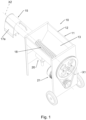
- a mixing machine for the preparation of mortars and plasters for the construction industry is indicated as a whole of a first embodiment thereof with the numeral 10.
- a mixing machine 10 as shown in figures 1 to 5 is known in technical jargon as a 'continuous mixer', particularly suitable for dry bagged mortars.
- Such a mixing machine 10 for preparing mortar comprises:
- the pumping means 20 and the drive means 21 are to be understood as being known per se.
- the pumping means 20 may, for example, comprise a pump driven by the same drive means 21, or with an autonomous and independent drive; the pumping means 20 may also be other, technically equivalent, means.
- the drive means 21 may for example comprise an electric motor configured to transmit rotation to the feed screw 18 via a belt system, or by other technically equivalent means known per se.
- the mixing tool 19 comprises a rotating longitudinal body 25 placed to rotate about a longitudinal axis X2 thereof, at least one flexible scraping element 26 developing from said rotating longitudinal body 25, configured to be arranged in contact with the inner surface 22 of the tubular mixing chamber 15 at least when the rotating longitudinal body 25 rotates about its longitudinal axis X2.
- This flexible scraping element 26 develops in the direction of the longitudinal axis X2 between two connection points 28 and 29 with the rotating longitudinal body 25.
- the mixing machine 10 belonging to the 'continuous mixer' type, has the tubular mixing chamber 15 positioned with a horizontal axis; consequently, the longitudinal axis of the rotating longitudinal body 25 is also substantially horizontal.
- the rotating longitudinal body 25 comprises a rotation shaft 30.
- Such rotation shaft 30 is of such a length that it longitudinally crosses the tubular mixing chamber 15 from the inlet opening 16 to the unloading mouth 17.
- the unloading mouth 17 is open downwards.
- a collar 17a for directing the outlet jet and possibly a jet breaker grille 17b may be positioned below the unloading mouth 17.
- the rotating longitudinal body 25 comprises mixing paddles 23, radially developing from the rotation shaft 30; said mixing paddles 23 extend radially up to a predetermined distance from the inner surface 22 of the tubular mixing chamber 15, for example about 1 cm, in order to prevent the same paddles 23 from crashing against a layer, or coating, of material that may form on said inner surface 22.
- the mixing paddles 23 are to be understood to be of a known type in themselves, and are to be understood to be of various shapes and sizes according to needs and technical requirements.
- such mixing paddles 23 comprise:
- the flexible scraping element 26 comprises a cable made of metallic material 27, hereinafter also referred to as 'metal cable' for brevity; in particular, the flexible scraping element 26 comprises a metal cable 27.
- a metal cable 27 makes it possible to have a flexible scraping element 26 that is self-supporting when not in use, i.e. it does not bend downwards by gravity, and at the same time, thanks to its mass, when it is drawn in rotation it is pushed against the inner surface 22 of the tubular mixing chamber 15 by the centrifugal force.
- the flexibility of the metal cable 27 allows easy removal of the mixing tool 19 from the tubular mixing chamber 15, for example for cleaning operations, or for replacement or maintenance of the mixing tool 19 itself.
- connection points 28 and 29 to the rotation shaft 30 are positioned one in proximity to the inlet opening 16 and one in proximity to the unloading mouth 17, respectively.
- the metal cable 27 is constrained to at least one of the two connection points in such a way that it does not translate in a radial direction in relation to said longitudinal axis X2.
- the metal cable 27 is constrained to the rotation shaft 30 at both connection points 28 and 29 in such a way that it does not translate in the radial direction with respect to the longitudinal axis X2, unless there is clearance; this clearance is understood to be comprised between 1 mm and 10 mm.
- a first end 27a of the metal cable 27 is inserted and fixed into a locking collar which is in turn fixed to a mixing paddle 23; in this way, the first end 27a is not able to move in a radial direction with respect to the longitudinal axis X2.
- a second end 27b of the metal cable 27 is placed to cross the rotation shaft 30 in a corresponding through-hole diametrically defined on the same rotation shaft 30 at a second connection point 29.
- This second end 27b is fixed to the rotation shaft 30 by means of two clamps 27c, opposite with respect to the diameter of the rotation shaft 30, which prevent the second end 27b from moving radially, except for physiological millimetre level clearance.
- one or both of the ends 27a and 27b are constrained to the rotation shaft 30 by means which allow free translation in a radial direction; this free translation is intended to be able to take place over a length of, for example, between 2 cm and 10 cm, where the translation limits are imposed by corresponding mechanical limit switches.
- Figure 3 clearly shows how the flexible scraping element 26 is arranged in contact with the inner surface 22 and is able, by rotating about the longitudinal axis X2, to remove the coating, or layer, of material from it, which would otherwise adhere to the inner surface 22 creating the undesired blocking of the space between the mixing paddles 23 and the same inner surface 22.
- the mixing machine 10 may also comprise a mixing tool 19 in turn comprising an auxiliary flexible scraping element 31, as well exemplified in figures 2 to 5 .
- This auxiliary flexible scraping element 31 also develops in the direction of the longitudinal axis X2 between two connection points 32 and 33 with the rotating longitudinal body 25, i.e., in particular, with the rotation shaft 30.
- the auxiliary flexible scraping element 31 is positioned at the unloading mouth 17 and is of a size such that it passes through at least part of said unloading mouth 17 during rotation, as shown in the schematic section of figure 5 .
- the auxiliary flexible scraping element 31 comprises an auxiliary metal cable 34, hereinafter referred to as 'auxiliary metal cable 34'; in particular, the auxiliary flexible scraping element 31 consists of an auxiliary metal cable 34.
- Said auxiliary metal cable 34 is constrained with the rotation shaft 30 by a first end 34a thereof to at least one of the two connection points, for example to a first connection point 32, so as to translate in a radial direction with respect to said longitudinal axis X2.
- the first end 34a of the auxiliary metal cable 34 is positioned to pass through a diametrical through-hole defined on the rotation shaft 30.
- the first end 34a has an anti-extraction head 34c, which is larger than the cross-section of the through-hole on the rotation shaft 30.
- a second end 34b of the auxiliary metal cable 34 is fixed to the rotation shaft 30 by means of two clamps 37, opposite with respect to the diameter of the rotation shaft 30, which prevent the second end 34b from moving radially, except for physiological millimetre level clearance.
- the auxiliary metal cable 34 is therefore of such a length that, in the maximum radial extension arrangement between the two connection points 32 and 33, it touches the flow-breaker grille 17b.
- the flexible scraping element 26 and the auxiliary flexible scraping element 31 are advantageously and suitably angularly offset from the longitudinal axis X2, of rotation; for example, the flexible scraping element 26 and the auxiliary flexible scraping element 31 are offset by 90°.
- the flexible scraping element 26 and the auxiliary flexible scraping element 31 are mounted on the rotation shaft 30 in such a way that they are not pinched between the mixing paddles 23 and the inner surface 22 of the tubular mixing chamber 15.
- the flexible scraping element 26 and the auxiliary flexible scraping element 31 are mounted on the rotation shaft so as to follow the mixing paddles 23 with respect to the direction of rotation of the mixing tool 19.
- the feed screw 18 and the mixing tool 19 are generally coaxial.
- the feed screw 18 and the mixing tool 19 are coaxially connected by an intermediate joint 38, clearly visible in figures 3 , 4 and 5 , provided with an auxiliary feed propeller 38b, the latter being shown in figure 5 .
- Said intermediate joint 38 has a scraping relief 38a, visible in figure 3 , configured to rub against the inner surface in the tubular compartment 39 in which the intermediate joint 38 is housed.
- the scraping relief 38a comprises a piece of metal cable fixed to protrude from the auxiliary propeller 38b of the intermediate joint 38.
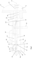
- a variant embodiment of a mixing tool 519 is schematically shown in figure 6 .
- the mixing tool 519 comprises a rotating longitudinal body 525 placed to rotate about a longitudinal axis X2 thereof, two flexible scraping elements 526a and 526b developing from such rotating longitudinal body 525, configured to arrange themselves in contact with the inner surface 22 of the tubular mixing chamber 15 at least when the rotating longitudinal body 525 rotates about its longitudinal axis X2.
- Such flexible scraping elements 526a and 526b develop in the direction of the longitudinal axis X2 between two connection points 528 and 529 and 532 and 533 respectively, with the rotating longitudinal body 525.
- the rotating longitudinal body 525 comprises a rotation shaft 530.
- the flexible scraping elements 526a and 526b both consist of a respective metal cable 570 and 571.
- Each metal cable 570 and 571 develops in an 'S'-shaped line from one end of a rotation shaft 530 to the other, diametrically crossing the same rotation shaft 530 in a central area thereof.
- the two metal cables 570 and 571 are advantageously and appropriately offset at an angle with respect to the longitudinal axis X2, of rotation; for example, the two metal cables 570 and 571 are offset by 90°.
- the ends of the cables are constrained to the rotation shaft 530 in the same way as described above for the cables 27 and 34 made of metallic material.
- the mixing tool 519 has no mixing paddles, but the same flexible scraping elements 526a and 526b also have the mixing function.
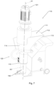
- Figures 7 to 9 show a second embodiment of a mixing machine according to the invention, referred to therein as number 110.
- the mixing machine 110 in this second embodiment is known in technical jargon as a 'plastering machine', of the vertical axis type, particularly for glues for installing external coatings, and therefore in general for very sticky materials.
- Such a mixing machine 110 comprises:
- the feed screw 118 comprises a bent bar 118a, developing along a substantially helical line; such bent bar 118a is fixed to a rotation shaft 118b, also intended to be part of the feed screw 118.
- the mixing tool 119 comprises a rotating longitudinal body 125 placed to rotate about a longitudinal axis X2 thereof.
- a flexible scraping element 126 develops, configured to be in contact with the inner surface 122 of the tubular mixing chamber 115 at least when the rotating longitudinal body 125 rotates about its longitudinal axis X2.
- the flexible scraping element 126 develops in the direction of said longitudinal axis X2 between two connection points 128 and 129 with said rotating longitudinal body 125.
- the mixing machine 110 has a tubular mixing chamber 115 positioned at a vertical axis X3.
- the rotating longitudinal body 125 comprises a fork 130 whose two opposite symmetrical arms 130a, 130b develop in an axial direction parallel to the inner surface 122 of said tubular mixing chamber 115.
- Said arms 130a and 130b develop between an upper crosspiece 135, connecting to said feed screw 118, and a lower crosspiece 136 placed between the lower ends of said arms 130a, 130b.
- the flexible scraping element 126 comprises a cable made of metallic material 127, constrained to the rotating longitudinal body 125 between two connection points 128, 129, a first connection point 128 being defined at the upper crosspiece 135, a second connection point 129 being defined at the lower crosspiece 136.
- the metal cable 127 also develops from the second connection point 129, which is lower, to a third connection point 128a, which is higher, located at the upper crosspiece 135 on the opposite side with respect to the first connection point 128.
- the second connection point 129 is preferably, but not exclusively, defined at the centre of the lower crosspiece 136.
- the metal cable 127 develops between said first 128 and second 129 connection points and between said second 129 and third 128b connection points according to a substantially helical line.
- the metal cable 127 is configured to promote the advancement of the material being mixed.
- the second connection point 129 is defined, for example, by an annular element fixed to the lower crosspiece 136.
- the metal cable 127 can be tied to the connection points 128, 129, 128a in the same way as described above for the metal cables 27 and 34 relating to the first embodiment of the invention, i.e. such cable can be fixed at both ends, or have the possibility of sliding for at least one of the two ends.
- the mixing machine 110 is to be understood to comprise, below the tubular mixing chamber 115, a spray pump 150, in a known manner per se, which spray pump is coaxially connected to the mixing tool 119, as exemplified in figure 9 .
- the rotation shaft 118b of the feed screw 118 is rigidly fixed in the axial direction to the fork 130 of the mixing tool 119, for example, but not exclusively, by welding.
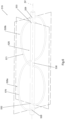
- Figures 10 and 11 show a third embodiment of a mixing machine according to the invention, which is indicated therein by the number 210.
- the mixing machine 210 in this third embodiment is also known in technical jargon as the 'plastering machine'.
- the tubular mixing chamber 215 is positioned at an axis X4 inclined with respect to the ground by an angle comprised between 20° and 70°.
- the rotating longitudinal body 225 of the mixing tool 219 comprises a fork 230 whose two opposite symmetrical arms 230a, 230b develop in an axial direction parallel to the inner surface of said tubular mixing chamber 215.
- the arms 230a, 230b develop between an upper crosspiece 235, connecting with the feed screw 218, and a lower crosspiece 236 placed between the lower ends of said arms 230a, 230b.
- the flexible scraping element 226 comprises a cable 227 made of metallic material, constrained to the rotating longitudinal body 225 between two connection points 228, 229, a first connection point 228 being defined at said upper crosspiece 235, and a second connection point 229 being defined at said lower crosspiece 236.
- the cable 227 made of metallic material also develops from the second connection point 229, which is lower, to a third connection point 228a, which is higher, located at the upper crosspiece 235 on the opposite side with respect to the first connection point 228.
- the metal cable 227 develops between said first 228 and second 229 connection points and between said second 229 and third 228b connection points according to a substantially helical line.
- the metal cable 227 is configured to promote the advancement of the material being mixed.
- the second connection point 229 is defined, for example, by an annular element fixed to the lower crosspiece 236.
- This second point of connection 229 is preferably, but not exclusively, defined at the centre of the lower crosspiece 236.
- the mixing machine 210 comprises a spray pump 250 coaxially connected to the mixing tool 219.
- the flexible scraping element 326 comprises:
- Such an anti-pinch terminal 340 may for example comprise a spherical body, which is larger than the distance between the inner surface of the tubular mixing chamber and the outer surface of the arms 330a and 330b of the fork 330.
- Such an anti-pinch terminal 340 has the double function of preventing the end 327a of the metal cable 327 from being pinched between the fork 330 and the inner surface of the mixing chamber, and striking the same inner surface promoting the detachment of the material that may have adhered to it.
- the metal cable 327 is constrained to the rotating longitudinal body 325 between two connection points 328, 329, where a first connection point 328 is defined at a lateral side of the upper crosspiece 335 with respect to the longitudinal axis X2 of the mixing tool 319, and the second connection point 329 is defined at the opposite side of the lower crosspiece 336 with respect to the same longitudinal axis X2.
- Such a configuration is easier to make and easier to assemble than the embodiments of the invention described above.
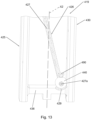
- the flexible scraping element 426 comprises a cable 427 made of metallic material, constrained to the rotating longitudinal body 425 between two connection points, a first connection point being defined at the upper crosspiece, not illustrated for simplicity and to be understood as analogous to what is represented in figure 12 , and a second connection point 429 being defined at said lower crosspiece 436.
- the lower end 427a of the metal cable 427 is fixed to a terminal 440 which is in turn fixed to the lower crosspiece 436.
- the lower end 427a is fixed by means of a threaded element 490 which is designed to press in a radial direction on the lower end 427a through a corresponding radial threaded hole made on the terminal 440.
- the terminal 440 consists of a spherical body made of metallic material.
- the fixing means of the lower end 427a to the rotating longitudinal body 425, and in particular to the fork 430, are to be understood to be also other, similar and technically equivalent means.
- the metal cable 427 is constrained to the rotating longitudinal body 425 between two connection points, where a first connection point is defined at a lateral side of the upper crosspiece with respect to the longitudinal axis X2 of the mixing tool 419, and the second connection point 429 is defined at the opposite side of the lower crosspiece 436 with respect to the same longitudinal axis X2.
- the flexible scraping elements described above as defined by a cable made of metallic material, are to be understood to be capable of being made with other technically equivalent flexible elements, for example with predominantly longitudinal developing bodies made of plastic.
- the mixer of the invention simplifies mortar and plaster mixing operations and has better reliability than known mixers which require frequent manual intervention during operation.
- the invention provides a mixing machine whose tubular mixing chamber is easy to clean, even when dry, thanks to the constant scraping work that one or more metal cables perform against the inner surface of the tubular mixing chamber at the same time as the mixing operation itself.
- the invention provides a mixing machine which allows to obtain a more constant output flow rate of mortar or plaster than similar machines of the known type, by preventing the formation of a thick layer of material on the inner surface of the tubular mixing chamber, a layer of material which, by coming detached irregularly from the inner surface, would alter the flow rate and density of the output mixture.
- a mixing machine which makes it possible to obtain at the outlet a mortar or a plaster having a more stable density, i.e. less variable, than similar machines of the known type; thanks to the 'whip' effect of the scraping metal cable, when mixing the residual material which in known machines sticks to the inner surface, in the mixing machine according to the invention this residual material no longer sticks, and therefore it no longer happens that the material suddenly detaches, mixing with the material being mixed and thus overturning the predetermined density of the material being mixed.
- the invention provides a mixing machine that is structurally simple and easy and cheap to maintain.
- the invention further provides a mixing machine that can be set up in a number of different configurations according to needs and technical requirements.
- the aim of maintaining a constant flow rate of mixed material coming out of the mixing machine is achieved, reducing the need for operators to continuously intervene through manual operations.
Landscapes
- Chemical & Material Sciences (AREA)
- Chemical Kinetics & Catalysis (AREA)
- Engineering & Computer Science (AREA)
- Mechanical Engineering (AREA)
- Structural Engineering (AREA)
- Mixers Of The Rotary Stirring Type (AREA)
- Curing Cements, Concrete, And Artificial Stone (AREA)
Applications Claiming Priority (1)
| Application Number | Priority Date | Filing Date | Title |
|---|---|---|---|
| IT102021000003770A IT202100003770A1 (it) | 2021-02-18 | 2021-02-18 | Macchina di mescolamento per la preparazione di malte e intonaci per l'edilizia |
Publications (2)
| Publication Number | Publication Date |
|---|---|
| EP4046705A1 EP4046705A1 (en) | 2022-08-24 |
| EP4046705B1 true EP4046705B1 (en) | 2023-12-20 |
Family
ID=75769813
Family Applications (1)
| Application Number | Title | Priority Date | Filing Date |
|---|---|---|---|
| EP22157543.4A Active EP4046705B1 (en) | 2021-02-18 | 2022-02-18 | Mixing machine for the preparation of mortars and plasters for the construction industry |
Country Status (5)
| Country | Link |
|---|---|
| EP (1) | EP4046705B1 (es) |
| ES (1) | ES2974170T3 (es) |
| IT (1) | IT202100003770A1 (es) |
| PL (1) | PL4046705T3 (es) |
| PT (1) | PT4046705T (es) |
Families Citing this family (1)
| Publication number | Priority date | Publication date | Assignee | Title |
|---|---|---|---|---|
| CN118257249B (zh) * | 2024-05-30 | 2024-08-02 | 华侨大学 | 一种处理工业废渣软土的固化装置 |
Family Cites Families (3)
| Publication number | Priority date | Publication date | Assignee | Title |
|---|---|---|---|---|
| DE3241193A1 (de) * | 1982-11-08 | 1984-05-10 | Dietrich Dipl.-Ing. 6240 Königstein Maurer | Vorrichtung zum kontinuierlichen mischen von trockengut mit einer fluessigkeit und foerdern des mischgutes |
| JP3004640B1 (ja) * | 1999-01-12 | 2000-01-31 | 東海サンド株式会社 | 材料混練装置 |
| CN204748925U (zh) * | 2015-06-05 | 2015-11-11 | 杭州波欣工程机械有限公司 | 螺旋搅拌机 |
-
2021
- 2021-02-18 IT IT102021000003770A patent/IT202100003770A1/it unknown
-
2022
- 2022-02-18 ES ES22157543T patent/ES2974170T3/es active Active
- 2022-02-18 PT PT221575434T patent/PT4046705T/pt unknown
- 2022-02-18 EP EP22157543.4A patent/EP4046705B1/en active Active
- 2022-02-18 PL PL22157543.4T patent/PL4046705T3/pl unknown
Also Published As
| Publication number | Publication date |
|---|---|
| ES2974170T3 (es) | 2024-06-26 |
| IT202100003770A1 (it) | 2022-08-18 |
| PT4046705T (pt) | 2024-03-14 |
| PL4046705T3 (pl) | 2024-04-29 |
| EP4046705A1 (en) | 2022-08-24 |
Similar Documents
| Publication | Publication Date | Title |
|---|---|---|
| EP4046705B1 (en) | Mixing machine for the preparation of mortars and plasters for the construction industry | |
| JP2610340B2 (ja) | 連続混合装置 | |
| US6123445A (en) | Dual stage continuous mixing apparatus | |
| EP2937137B1 (de) | Mischmaschine | |
| KR0178701B1 (ko) | 벌크-재료/액체 혼합물용 수송 혼합기 | |
| JP6786222B2 (ja) | モルタル混練ミキサー装置 | |
| US7270469B2 (en) | Apparatus and method for adding pigmentation to concrete mix | |
| CZ176593A3 (en) | Apparatus for the production in the site of mortars suitable for pumping | |
| NZ214599A (en) | Rotary concrete mixer with inner rotor made from resilient material | |
| JPH0679076B2 (ja) | 混合装置 | |
| CN103817069A (zh) | 用于砂石分离的滚筒 | |
| KR102186976B1 (ko) | 교반장치 | |
| CN219616646U (zh) | 具有自动清洁功能的混砂机 | |
| US3414168A (en) | Apparatus for feeding particulate materials | |
| JP2010082921A (ja) | コンクリートミキサ、コンクリートミキサの洗浄方法、及び生コンクリートの製造方法 | |
| CN115337839A (zh) | 物料处理装置 | |
| CN110624433A (zh) | 搅拌装置及搅拌机器人 | |
| CN109823719B (zh) | 用于粉末产品的配料装置 | |
| CN209406330U (zh) | 一种搅拌均匀的反应釜 | |
| CN103357338A (zh) | 一种电动搅拌机 | |
| CN215483175U (zh) | 一种自清式环保工程用排泥设备 | |
| KR100828990B1 (ko) | 슬러지 저장용 싸이로 | |
| CN113843892B (zh) | 一种改性浓缩全尾砂浆制备装置 | |
| RU2827370C1 (ru) | Шнековый питатель | |
| CN220990410U (zh) | 一种物料混合装置 |
Legal Events
| Date | Code | Title | Description |
|---|---|---|---|
| PUAI | Public reference made under article 153(3) epc to a published international application that has entered the european phase |
Free format text: ORIGINAL CODE: 0009012 |
|
| STAA | Information on the status of an ep patent application or granted ep patent |
Free format text: STATUS: THE APPLICATION HAS BEEN PUBLISHED |
|
| AK | Designated contracting states |
Kind code of ref document: A1 Designated state(s): AL AT BE BG CH CY CZ DE DK EE ES FI FR GB GR HR HU IE IS IT LI LT LU LV MC MK MT NL NO PL PT RO RS SE SI SK SM TR |
|
| STAA | Information on the status of an ep patent application or granted ep patent |
Free format text: STATUS: REQUEST FOR EXAMINATION WAS MADE |
|
| 17P | Request for examination filed |
Effective date: 20230221 |
|
| RBV | Designated contracting states (corrected) |
Designated state(s): AL AT BE BG CH CY CZ DE DK EE ES FI FR GB GR HR HU IE IS IT LI LT LU LV MC MK MT NL NO PL PT RO RS SE SI SK SM TR |
|
| GRAP | Despatch of communication of intention to grant a patent |
Free format text: ORIGINAL CODE: EPIDOSNIGR1 |
|
| STAA | Information on the status of an ep patent application or granted ep patent |
Free format text: STATUS: GRANT OF PATENT IS INTENDED |
|
| RIC1 | Information provided on ipc code assigned before grant |
Ipc: B28C 5/16 20060101ALI20230629BHEP Ipc: B28C 5/14 20060101ALI20230629BHEP Ipc: B01F 27/90 20220101ALI20230629BHEP Ipc: B01F 27/70 20220101ALI20230629BHEP Ipc: B01F 27/60 20220101ALI20230629BHEP Ipc: B01F 27/213 20220101ALI20230629BHEP Ipc: B01F 27/2123 20220101ALI20230629BHEP Ipc: B01F 27/2121 20220101ALI20230629BHEP Ipc: B01F 27/13 20220101ALI20230629BHEP Ipc: B01F 27/091 20220101AFI20230629BHEP |
|
| INTG | Intention to grant announced |
Effective date: 20230713 |
|
| GRAS | Grant fee paid |
Free format text: ORIGINAL CODE: EPIDOSNIGR3 |
|
| GRAA | (expected) grant |
Free format text: ORIGINAL CODE: 0009210 |
|
| STAA | Information on the status of an ep patent application or granted ep patent |
Free format text: STATUS: THE PATENT HAS BEEN GRANTED |
|
| AK | Designated contracting states |
Kind code of ref document: B1 Designated state(s): AL AT BE BG CH CY CZ DE DK EE ES FI FR GB GR HR HU IE IS IT LI LT LU LV MC MK MT NL NO PL PT RO RS SE SI SK SM TR |
|
| REG | Reference to a national code |
Ref country code: GB Ref legal event code: FG4D |
|
| REG | Reference to a national code |
Ref country code: DE Ref legal event code: R096 Ref document number: 602022001322 Country of ref document: DE |
|
| REG | Reference to a national code |
Ref country code: CH Ref legal event code: EP |
|
| REG | Reference to a national code |
Ref country code: IE Ref legal event code: FG4D |
|
| REG | Reference to a national code |
Ref country code: PT Ref legal event code: SC4A Ref document number: 4046705 Country of ref document: PT Date of ref document: 20240314 Kind code of ref document: T Free format text: AVAILABILITY OF NATIONAL TRANSLATION Effective date: 20240308 |
|
| REG | Reference to a national code |
Ref country code: NL Ref legal event code: FP |
|
| PG25 | Lapsed in a contracting state [announced via postgrant information from national office to epo] |
Ref country code: GR Free format text: LAPSE BECAUSE OF FAILURE TO SUBMIT A TRANSLATION OF THE DESCRIPTION OR TO PAY THE FEE WITHIN THE PRESCRIBED TIME-LIMIT Effective date: 20240321 |
|
| REG | Reference to a national code |
Ref country code: LT Ref legal event code: MG9D |
|
| PG25 | Lapsed in a contracting state [announced via postgrant information from national office to epo] |
Ref country code: LT Free format text: LAPSE BECAUSE OF FAILURE TO SUBMIT A TRANSLATION OF THE DESCRIPTION OR TO PAY THE FEE WITHIN THE PRESCRIBED TIME-LIMIT Effective date: 20231220 |
|
| PG25 | Lapsed in a contracting state [announced via postgrant information from national office to epo] |
Ref country code: LT Free format text: LAPSE BECAUSE OF FAILURE TO SUBMIT A TRANSLATION OF THE DESCRIPTION OR TO PAY THE FEE WITHIN THE PRESCRIBED TIME-LIMIT Effective date: 20231220 Ref country code: GR Free format text: LAPSE BECAUSE OF FAILURE TO SUBMIT A TRANSLATION OF THE DESCRIPTION OR TO PAY THE FEE WITHIN THE PRESCRIBED TIME-LIMIT Effective date: 20240321 Ref country code: FI Free format text: LAPSE BECAUSE OF FAILURE TO SUBMIT A TRANSLATION OF THE DESCRIPTION OR TO PAY THE FEE WITHIN THE PRESCRIBED TIME-LIMIT Effective date: 20231220 Ref country code: BG Free format text: LAPSE BECAUSE OF FAILURE TO SUBMIT A TRANSLATION OF THE DESCRIPTION OR TO PAY THE FEE WITHIN THE PRESCRIBED TIME-LIMIT Effective date: 20240320 |
|
| P01 | Opt-out of the competence of the unified patent court (upc) registered |
Effective date: 20240328 |
|
| PG25 | Lapsed in a contracting state [announced via postgrant information from national office to epo] |
Ref country code: SE Free format text: LAPSE BECAUSE OF FAILURE TO SUBMIT A TRANSLATION OF THE DESCRIPTION OR TO PAY THE FEE WITHIN THE PRESCRIBED TIME-LIMIT Effective date: 20231220 Ref country code: RS Free format text: LAPSE BECAUSE OF FAILURE TO SUBMIT A TRANSLATION OF THE DESCRIPTION OR TO PAY THE FEE WITHIN THE PRESCRIBED TIME-LIMIT Effective date: 20231220 Ref country code: NO Free format text: LAPSE BECAUSE OF FAILURE TO SUBMIT A TRANSLATION OF THE DESCRIPTION OR TO PAY THE FEE WITHIN THE PRESCRIBED TIME-LIMIT Effective date: 20240320 Ref country code: LV Free format text: LAPSE BECAUSE OF FAILURE TO SUBMIT A TRANSLATION OF THE DESCRIPTION OR TO PAY THE FEE WITHIN THE PRESCRIBED TIME-LIMIT Effective date: 20231220 Ref country code: HR Free format text: LAPSE BECAUSE OF FAILURE TO SUBMIT A TRANSLATION OF THE DESCRIPTION OR TO PAY THE FEE WITHIN THE PRESCRIBED TIME-LIMIT Effective date: 20231220 |
|
| REG | Reference to a national code |
Ref country code: ES Ref legal event code: FG2A Ref document number: 2974170 Country of ref document: ES Kind code of ref document: T3 Effective date: 20240626 |
|
| PG25 | Lapsed in a contracting state [announced via postgrant information from national office to epo] |
Ref country code: IS Free format text: LAPSE BECAUSE OF FAILURE TO SUBMIT A TRANSLATION OF THE DESCRIPTION OR TO PAY THE FEE WITHIN THE PRESCRIBED TIME-LIMIT Effective date: 20240420 |
|
| PG25 | Lapsed in a contracting state [announced via postgrant information from national office to epo] |
Ref country code: CZ Free format text: LAPSE BECAUSE OF FAILURE TO SUBMIT A TRANSLATION OF THE DESCRIPTION OR TO PAY THE FEE WITHIN THE PRESCRIBED TIME-LIMIT Effective date: 20231220 |
|
| PG25 | Lapsed in a contracting state [announced via postgrant information from national office to epo] |
Ref country code: SK Free format text: LAPSE BECAUSE OF FAILURE TO SUBMIT A TRANSLATION OF THE DESCRIPTION OR TO PAY THE FEE WITHIN THE PRESCRIBED TIME-LIMIT Effective date: 20231220 |
|
| PG25 | Lapsed in a contracting state [announced via postgrant information from national office to epo] |
Ref country code: SM Free format text: LAPSE BECAUSE OF FAILURE TO SUBMIT A TRANSLATION OF THE DESCRIPTION OR TO PAY THE FEE WITHIN THE PRESCRIBED TIME-LIMIT Effective date: 20231220 Ref country code: SK Free format text: LAPSE BECAUSE OF FAILURE TO SUBMIT A TRANSLATION OF THE DESCRIPTION OR TO PAY THE FEE WITHIN THE PRESCRIBED TIME-LIMIT Effective date: 20231220 Ref country code: RO Free format text: LAPSE BECAUSE OF FAILURE TO SUBMIT A TRANSLATION OF THE DESCRIPTION OR TO PAY THE FEE WITHIN THE PRESCRIBED TIME-LIMIT Effective date: 20231220 Ref country code: IS Free format text: LAPSE BECAUSE OF FAILURE TO SUBMIT A TRANSLATION OF THE DESCRIPTION OR TO PAY THE FEE WITHIN THE PRESCRIBED TIME-LIMIT Effective date: 20240420 Ref country code: EE Free format text: LAPSE BECAUSE OF FAILURE TO SUBMIT A TRANSLATION OF THE DESCRIPTION OR TO PAY THE FEE WITHIN THE PRESCRIBED TIME-LIMIT Effective date: 20231220 Ref country code: CZ Free format text: LAPSE BECAUSE OF FAILURE TO SUBMIT A TRANSLATION OF THE DESCRIPTION OR TO PAY THE FEE WITHIN THE PRESCRIBED TIME-LIMIT Effective date: 20231220 |
|
| REG | Reference to a national code |
Ref country code: AT Ref legal event code: UEP Ref document number: 1642025 Country of ref document: AT Kind code of ref document: T Effective date: 20231220 |
|
| REG | Reference to a national code |
Ref country code: DE Ref legal event code: R097 Ref document number: 602022001322 Country of ref document: DE |
|
| PG25 | Lapsed in a contracting state [announced via postgrant information from national office to epo] |
Ref country code: MC Free format text: LAPSE BECAUSE OF FAILURE TO SUBMIT A TRANSLATION OF THE DESCRIPTION OR TO PAY THE FEE WITHIN THE PRESCRIBED TIME-LIMIT Effective date: 20231220 |
|
| PG25 | Lapsed in a contracting state [announced via postgrant information from national office to epo] |
Ref country code: DK Free format text: LAPSE BECAUSE OF FAILURE TO SUBMIT A TRANSLATION OF THE DESCRIPTION OR TO PAY THE FEE WITHIN THE PRESCRIBED TIME-LIMIT Effective date: 20231220 |
|
| PG25 | Lapsed in a contracting state [announced via postgrant information from national office to epo] |
Ref country code: LU Free format text: LAPSE BECAUSE OF NON-PAYMENT OF DUE FEES Effective date: 20240218 |
|
| PLBE | No opposition filed within time limit |
Free format text: ORIGINAL CODE: 0009261 |
|
| STAA | Information on the status of an ep patent application or granted ep patent |
Free format text: STATUS: NO OPPOSITION FILED WITHIN TIME LIMIT |
|
| PG25 | Lapsed in a contracting state [announced via postgrant information from national office to epo] |
Ref country code: SI Free format text: LAPSE BECAUSE OF FAILURE TO SUBMIT A TRANSLATION OF THE DESCRIPTION OR TO PAY THE FEE WITHIN THE PRESCRIBED TIME-LIMIT Effective date: 20231220 |
|
| PG25 | Lapsed in a contracting state [announced via postgrant information from national office to epo] |
Ref country code: SI Free format text: LAPSE BECAUSE OF FAILURE TO SUBMIT A TRANSLATION OF THE DESCRIPTION OR TO PAY THE FEE WITHIN THE PRESCRIBED TIME-LIMIT Effective date: 20231220 Ref country code: LU Free format text: LAPSE BECAUSE OF NON-PAYMENT OF DUE FEES Effective date: 20240218 Ref country code: DK Free format text: LAPSE BECAUSE OF FAILURE TO SUBMIT A TRANSLATION OF THE DESCRIPTION OR TO PAY THE FEE WITHIN THE PRESCRIBED TIME-LIMIT Effective date: 20231220 |
|
| 26N | No opposition filed |
Effective date: 20240923 |
|
| PG25 | Lapsed in a contracting state [announced via postgrant information from national office to epo] |
Ref country code: IE Free format text: LAPSE BECAUSE OF NON-PAYMENT OF DUE FEES Effective date: 20240218 |
|
| PG25 | Lapsed in a contracting state [announced via postgrant information from national office to epo] |
Ref country code: IE Free format text: LAPSE BECAUSE OF NON-PAYMENT OF DUE FEES Effective date: 20240218 |
|
| PGFP | Annual fee paid to national office [announced via postgrant information from national office to epo] |
Ref country code: PT Payment date: 20250206 Year of fee payment: 4 |
|
| PGFP | Annual fee paid to national office [announced via postgrant information from national office to epo] |
Ref country code: PL Payment date: 20250207 Year of fee payment: 4 |
|
| PGFP | Annual fee paid to national office [announced via postgrant information from national office to epo] |
Ref country code: ES Payment date: 20250331 Year of fee payment: 4 |
|
| PG25 | Lapsed in a contracting state [announced via postgrant information from national office to epo] |
Ref country code: CY Free format text: LAPSE BECAUSE OF FAILURE TO SUBMIT A TRANSLATION OF THE DESCRIPTION OR TO PAY THE FEE WITHIN THE PRESCRIBED TIME-LIMIT; INVALID AB INITIO Effective date: 20220218 |
|
| REG | Reference to a national code |
Ref country code: CH Ref legal event code: PL |
|
| PG25 | Lapsed in a contracting state [announced via postgrant information from national office to epo] |
Ref country code: CH Free format text: LAPSE BECAUSE OF NON-PAYMENT OF DUE FEES Effective date: 20250228 |
|
| PG25 | Lapsed in a contracting state [announced via postgrant information from national office to epo] |
Ref country code: TR Free format text: LAPSE BECAUSE OF FAILURE TO SUBMIT A TRANSLATION OF THE DESCRIPTION OR TO PAY THE FEE WITHIN THE PRESCRIBED TIME-LIMIT Effective date: 20231220 |
|
| PGFP | Annual fee paid to national office [announced via postgrant information from national office to epo] |
Ref country code: NL Payment date: 20260218 Year of fee payment: 5 |
|
| PGFP | Annual fee paid to national office [announced via postgrant information from national office to epo] |
Ref country code: DE Payment date: 20260218 Year of fee payment: 5 |
|
| PGFP | Annual fee paid to national office [announced via postgrant information from national office to epo] |
Ref country code: AT Payment date: 20260301 Year of fee payment: 5 |
|
| PGFP | Annual fee paid to national office [announced via postgrant information from national office to epo] |
Ref country code: IT Payment date: 20251212 Year of fee payment: 5 Ref country code: BE Payment date: 20260218 Year of fee payment: 5 |
|
| PGFP | Annual fee paid to national office [announced via postgrant information from national office to epo] |
Ref country code: FR Payment date: 20260219 Year of fee payment: 5 |