EP4046404B1 - Bereitstellung von konnektivität für einen dienstbereich durch luftfahrzeuge mit probabilistischen methoden - Google Patents
Bereitstellung von konnektivität für einen dienstbereich durch luftfahrzeuge mit probabilistischen methoden Download PDFInfo
- Publication number
- EP4046404B1 EP4046404B1 EP20829758.0A EP20829758A EP4046404B1 EP 4046404 B1 EP4046404 B1 EP 4046404B1 EP 20829758 A EP20829758 A EP 20829758A EP 4046404 B1 EP4046404 B1 EP 4046404B1
- Authority
- EP
- European Patent Office
- Prior art keywords
- lighter
- aerial vehicles
- service
- probability
- air aerial
- Prior art date
- Legal status (The legal status is an assumption and is not a legal conclusion. Google has not performed a legal analysis and makes no representation as to the accuracy of the status listed.)
- Active
Links
Images




Classifications
-
- G—PHYSICS
- G05—CONTROLLING; REGULATING
- G05D—SYSTEMS FOR CONTROLLING OR REGULATING NON-ELECTRIC VARIABLES
- G05D1/00—Control of position, course, altitude or attitude of land, water, air or space vehicles, e.g. using automatic pilots
- G05D1/0011—Control of position, course, altitude or attitude of land, water, air or space vehicles, e.g. using automatic pilots associated with a remote control arrangement
- G05D1/0027—Control of position, course, altitude or attitude of land, water, air or space vehicles, e.g. using automatic pilots associated with a remote control arrangement involving a plurality of vehicles, e.g. fleet or convoy travelling
-
- H—ELECTRICITY
- H04—ELECTRIC COMMUNICATION TECHNIQUE
- H04W—WIRELESS COMMUNICATION NETWORKS
- H04W4/00—Services specially adapted for wireless communication networks; Facilities therefor
- H04W4/30—Services specially adapted for particular environments, situations or purposes
- H04W4/40—Services specially adapted for particular environments, situations or purposes for vehicles, e.g. vehicle-to-pedestrians [V2P]
- H04W4/44—Services specially adapted for particular environments, situations or purposes for vehicles, e.g. vehicle-to-pedestrians [V2P] for communication between vehicles and infrastructures, e.g. vehicle-to-cloud [V2C] or vehicle-to-home [V2H]
-
- G—PHYSICS
- G01—MEASURING; TESTING
- G01W—METEOROLOGY
- G01W1/00—Meteorology
- G01W1/10—Devices for predicting weather conditions
-
- G—PHYSICS
- G05—CONTROLLING; REGULATING
- G05D—SYSTEMS FOR CONTROLLING OR REGULATING NON-ELECTRIC VARIABLES
- G05D1/00—Control of position, course, altitude or attitude of land, water, air or space vehicles, e.g. using automatic pilots
- G05D1/04—Control of altitude or depth
- G05D1/06—Rate of change of altitude or depth
- G05D1/0607—Rate of change of altitude or depth specially adapted for aircraft
- G05D1/0615—Rate of change of altitude or depth specially adapted for aircraft to counteract a perturbation, e.g. gust of wind
-
- G—PHYSICS
- G08—SIGNALLING
- G08G—TRAFFIC CONTROL SYSTEMS
- G08G5/00—Traffic control systems for aircraft
- G08G5/30—Flight plan management
-
- G—PHYSICS
- G08—SIGNALLING
- G08G—TRAFFIC CONTROL SYSTEMS
- G08G5/00—Traffic control systems for aircraft
- G08G5/50—Navigation or guidance aids
- G08G5/56—Navigation or guidance aids for two or more aircraft
-
- H—ELECTRICITY
- H04—ELECTRIC COMMUNICATION TECHNIQUE
- H04B—TRANSMISSION
- H04B7/00—Radio transmission systems, i.e. using radiation field
- H04B7/14—Relay systems
- H04B7/15—Active relay systems
- H04B7/185—Space-based or airborne stations; Stations for satellite systems
- H04B7/18502—Airborne stations
- H04B7/18504—Aircraft used as relay or high altitude atmospheric platform
-
- H—ELECTRICITY
- H04—ELECTRIC COMMUNICATION TECHNIQUE
- H04B—TRANSMISSION
- H04B7/00—Radio transmission systems, i.e. using radiation field
- H04B7/14—Relay systems
- H04B7/15—Active relay systems
- H04B7/185—Space-based or airborne stations; Stations for satellite systems
- H04B7/18502—Airborne stations
- H04B7/18506—Communications with or from aircraft, i.e. aeronautical mobile service
-
- H—ELECTRICITY
- H04—ELECTRIC COMMUNICATION TECHNIQUE
- H04W—WIRELESS COMMUNICATION NETWORKS
- H04W16/00—Network planning, e.g. coverage or traffic planning tools; Network deployment, e.g. resource partitioning or cells structures
- H04W16/24—Cell structures
- H04W16/26—Cell enhancers or enhancement, e.g. for tunnels, building shadow
-
- H—ELECTRICITY
- H04—ELECTRIC COMMUNICATION TECHNIQUE
- H04W—WIRELESS COMMUNICATION NETWORKS
- H04W24/00—Supervisory, monitoring or testing arrangements
- H04W24/02—Arrangements for optimising operational condition
-
- H—ELECTRICITY
- H04—ELECTRIC COMMUNICATION TECHNIQUE
- H04B—TRANSMISSION
- H04B7/00—Radio transmission systems, i.e. using radiation field
- H04B7/14—Relay systems
- H04B7/15—Active relay systems
- H04B7/185—Space-based or airborne stations; Stations for satellite systems
- H04B7/18502—Airborne stations
- H04B7/18506—Communications with or from aircraft, i.e. aeronautical mobile service
- H04B7/18508—Communications with or from aircraft, i.e. aeronautical mobile service with satellite system used as relay, i.e. aeronautical mobile satellite service
-
- H—ELECTRICITY
- H04—ELECTRIC COMMUNICATION TECHNIQUE
- H04W—WIRELESS COMMUNICATION NETWORKS
- H04W16/00—Network planning, e.g. coverage or traffic planning tools; Network deployment, e.g. resource partitioning or cells structures
- H04W16/18—Network planning tools
-
- H—ELECTRICITY
- H04—ELECTRIC COMMUNICATION TECHNIQUE
- H04W—WIRELESS COMMUNICATION NETWORKS
- H04W84/00—Network topologies
- H04W84/02—Hierarchically pre-organised networks, e.g. paging networks, cellular networks, WLAN [Wireless Local Area Network] or WLL [Wireless Local Loop]
- H04W84/04—Large scale networks; Deep hierarchical networks
- H04W84/06—Airborne or Satellite Networks
Definitions
- aerial vehicles equipped with communications units for receiving and transmitting radio frequency or optical data.
- aerial vehicles travel according to trajectories specified in advance by a flight plan with time, speed, direction, location and other states of the vehicles determined within a small error range.
- Lighter-than-air (i.e., floating or gliding vehicles, such as balloons, gliders, drones with gliding capabilities) vehicles travel using wind patterns, and thus their trajectories cannot be planned in the same manner since they are influenced by, and sometimes adapt to, meteorological forces that are not well-predicted in advance of the flight. In other words, wind drive vehicles are largely navigated by forces that are not predicted accurately.
- Groups of lighter-than-air vehicles also are used in other applications, such as observing the earth, meteorological data collection, among other types of data collection, and conventional techniques have difficulty delivering such services in a consistent manner in view of said unpredictable wind and meteorological forces.
- a computing device may display a graphical interface that that includes one or more interface features to receive a request for use of bandwidth of a balloon network.
- the computing device may receive, via the graphical interface, input data corresponding to a bandwidth request for a first location, where the bandwidth request includes: (i) an indication of the first location and (ii) an indication of time.
- US 2014/0188377 A1 relates to methods and systems for determining trajectories for vehicles of a fleet of vehicles.
- US 2019/0281471 A1 describes a method for planning a high altitude platform-based communication network includes aggregating data from at least one data source. Based on the aggregated data, a plurality of network expansion potential scores are computed according to geographic location.
- US 9 635 706 B1 describes methods for determining fleet control policies to satisfy a sequence of coverage requirements.
- the invention is directed to methods for delivering coverage to a service area by aerial vehicles.
- a system is provided for delivering coverage by aerial vehicles to a service area and managing the airspace in which the fleet is operating.
- the aerial vehicles may be part of a fleet of aerial vehicles being deployed to deliver coverage to a plurality of service areas around the world.
- Trajectories for lighter-than-air vehicles may be simulated based on weather forecasts (including forecasted wind patterns) and characteristics of the vehicle itself. These simulations may include running an aerial vehicle through a group of navigation algorithms (e.g. any deterministic logic, any probabilistic-based logic, and any adaptation to the observed environment) in a given environment. In other examples, these simulations may be run as an ensemble, wherein a plurality of universes are randomly sampled from a prior distribution. Within each universe each vehicle operates according to its algorithms given a forecast and each vehicle's characteristics, and each vehicle adapts to its universe through the course of the simulation.
- weather forecasts including forecasted wind patterns
- These simulations may include running an aerial vehicle through a group of navigation algorithms (e.g. any deterministic logic, any probabilistic-based logic, and any adaptation to the observed environment) in a given environment.
- these simulations may be run as an ensemble, wherein a plurality of universes are randomly sampled from a prior distribution. Within each universe each vehicle operates according to its
- a simulation may be run, with wind conditions being observed during the simulation and incorporated into a variety of planning algorithms.
- this type of simulation may be run a number of times with different environments (e.g., a first environment, second environment, through to an nth environment), different wind forecasts, each simulation producing a different adaptive behavior by the vehicle(s). This generates a distribution of outcomes, from which statistics (e.g. what percentage of the time was my target service area covered) may be computed.
- Such simulations may be run for individual vehicles (i.e. single vehicle simulations), or for fleets (i.e. multi-vehicle simulations, where the vehicles have a shared information state, such as shared wind observations, and may also have a shared algorithm).
- Such simulations provide probabilities as to an individual lighter-than-air vehicle's ability to achieve an objective - objectives such as providing consistent connectivity services to a target location or area (hereafter referred to as "station") or remaining within a certain distance of a desired point - and for which time periods.
- station a target location or area
- time periods for which time periods.
- the airspace and service coverage management system may take a probabilistic approach to planning to achieve an objective.
- a group of aerial vehicles within a fleet may be staged by navigating them to a target region for arrival on a target date and maybe a target time range as well.
- the group may comprise aerial vehicles that are navigating in an independent (i.e., non-interdependent) manner (i.e., they are navigating independently of each other) based on each vehicle's individual characteristics, starting point, weather forecasts for areas the vehicle will pass through on its way to the destination for the time that the vehicle will be passing through, and other independent factors.
- the system may determine that forecasted wind patterns are favorable for lighter-than-air (e.g., floating or gliding) vehicles to station seek for the time period, and allow the group of vehicles to travel according to a station seeking flight policy to achieve an objective to provide coverage to the target area.
- lighter-than-air e.g., floating or gliding
- determining that forecasted wind patterns are favorable for lighter-than-air vehicles to station seek for the time period may include running simulations for at least one lighter-than-air vehicle within a target area (e.g., a predetermined radius) surrounding the station for a given time period, and determining whether one or more simulations results in the lighter-than-air vehicle remaining within the target area for most or all of the given time period.
- a target area e.g., a predetermined radius
- simulations may be run for each of a group of lighter-than-air vehicles (e.g., vehicles allocated to an objective related to the target station) to optimize for each vehicle to achieve the objective, and calculating an overall probability of service coverage of a target area for a time period of interest by the group of vehicles based on the resulting individual probabilities of each vehicle being able to provide coverage in that time period of interest (e.g., Pi through P n ) for the time period of interest.
- a group of lighter-than-air vehicles e.g., vehicles allocated to an objective related to the target station
- P D is the histogram of a vehicle's distance from a target location under a particular control strategy
- c is the random variable (greater than a desired service coverage threshold C) specifying percentage of time coverage that is achieved
- d is the distance of a particular balloon to the target
- r is the radius of coverage for the target location (e.g., an LTE antenna radius)
- n is the number of vehicles to ensure the probability P of a desired amount of coverage is sufficiently high.
- n may represent a number of homogeneous independent-identically-distributed vehicles (i.e., the vehicles are of the same type and characteristics, but independently operated). Sufficiently large n (number of vehicles) allows sizing the fleet to hit a particular service availability or coverage objective.
- a vehicles flight such as power consumption
- a vehicles flight may be managed or optimized, for example, allowing for wind-driven vehicles to travel (i.e., drift) farther from a target location when there are more vehicles (i.e., thus a higher total probability that at least one vehicle will be in a position to provide coverage at any given time) so that each individual vehicle does not need to expend more energy remaining within a smaller radius of the target location.
- each vehicle may reserve or redirect more power for communications, longer operation or service times, or other power consuming components or operations.
- PD may differ for each vehicle or each type of vehicle.
- determining that forecasted wind patterns are favorable for station seeking also may be based directly on wind forecasts (e.g., direction and speed of winds) for the time period at or around the station (e.g., certain levels of directionally heterogeneous winds in the forecast may indicate directly that a probabilistic approach is appropriate).
- wind forecasts e.g., direction and speed of winds
- certain levels of directionally heterogeneous winds in the forecast may indicate directly that a probabilistic approach is appropriate.
- a determination may be made that there is sufficient wind variability (i.e., chaos) in the forecast to automatically infer that the probabilities of coverage would be sufficiently high (i.e., meets or exceeds a probability of service coverage threshold) for lighter-than-air vehicles to navigate according to a station seeking flight policy.
- wind variability i.e., chaos
- Such a determination may be made based on test, simulation and/or historical data correlating wind patterns to station seeking performance.
- such a determination may be made based on a categorization algorithm, a steering potential metric, or a machine-learning-based trained neural net that takes in a wind forecast and estimates steering potential.
- coverage probability Pc or P(c > C) may be calculated to confirm that a probability of coverage threshold can be met by a group of n lighter-than-air vehicles (e.g., according to one or more of the equations above).
- “meeting" a threshold, or any variation thereof, means to meet or exceed a threshold as may be required or defined in a connectivity service planning system.
- the system does not need to schedule or plan a detailed (e.g., minute by minute) planned flight trajectory for a particular vehicle, or for each vehicle in a group, to service the target area for the entirety of a time period or a designated portion of a time period (i.e., schedule for vehicles to arrive at a target location in serial each to service for a window of time, for example, until a next vehicle arrives).
- a detailed (e.g., minute by minute) planned flight trajectory for a particular vehicle, or for each vehicle in a group to service the target area for the entirety of a time period or a designated portion of a time period (i.e., schedule for vehicles to arrive at a target location in serial each to service for a window of time, for example, until a next vehicle arrives).
- the system can rely on the probabilistic behavior of each vehicle acting independently to achieve the group coverage (or other) objective.
- the system may change its approach from determining an overall probability of service coverage by a group of vehicles for a target area to planning for individual vehicles to service the target area for particular portions of this other time period.
- the system may tune controllers to plan for connectivity service objectives based on varying levels and characteristics of wind.
- Machine-learned or classical controllers may be tuned for groups of vehicles having complementary characteristics, which together can satisfy a service coverage objective. For example, aerial vehicles with no lateral control may be scheduled for times when steering potential is high (i.e., favorable station seeking winds), and lateral-control equipped vehicles may be scheduled for times when the steering potential is medium. In other examples, you may combine multiple probability equations.
- This probabilistic approach further enables the system to tune controllers to plan based on levels and characteristics of wind.
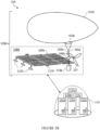
- FIGS. 1A-1B are diagrams of exemplary operational systems in which flight policies may be implemented for navigating an aerial vehicle, in accordance with one or more embodiments.
- FIG. 1A there is shown a diagram of system 100 for navigation of aerial vehicle 120a.
- aerial vehicle 120a may be a passive vehicle (e.g., balloon, glider, or (pseudo-)satellite), wherein most of its directional movement is a result of environmental forces, such as wind and gravity.
- aerial vehicles 120a may be actively propelled (i.e., powered).
- system 100 may include aerial vehicle 120a and ground station 114.
- aerial vehicle 120a may include balloon 101a, plate 102, altitude control system (ACS) 103a, connection 104a, joint 105a, actuation module 106a, and payload 108a.
- plate 102 may provide structural and electrical connections and infrastructure. Plate 102 may be positioned at the apex of balloon 101a and may serve to couple together various parts of balloon 101a. In other examples, plate 102 also may include a flight termination unit, such as one or more blades and an actuator to selectively cut a portion and/or a layer of balloon 101a.
- ACS 103a may include structural and electrical connections and infrastructure, including components (e.g., fans, valves, actuators, etc.) used to, for example, add and remove air from balloon 101a (i.e., in some examples, balloon 101a may include an interior ballonet within its outer, more rigid shell that is inflated and deflated), causing balloon 101a to ascend or descend, for example, to catch stratospheric winds to move in a desired direction.
- components e.g., fans, valves, actuators, etc.
- Balloon 101a may comprise a balloon envelope comprised of lightweight and/or flexible latex or rubber materials (e.g., polyethylene, polyethylene terephthalate, chloroprene), tendons (e.g., attached at one end to plate 102 and at another end to ACS 103a) to provide strength to the balloon structure, a ballonet, along with other structural components.
- lightweight and/or flexible latex or rubber materials e.g., polyethylene, polyethylene terephthalate, chloroprene
- tendons e.g., attached at one end to plate 102 and at another end to ACS 103a
- Connection 104a may structurally, electrically, and communicatively, connect balloon 101a and/or ACS 103a to various components comprising payload 108a.
- connection 104a may provide two-way communication and electrical connections, and even two-way power connections.
- Connection 104a may include a joint 105a, configured to allow the portion above joint 105a to pivot about one or more axes (e.g., allowing either balloon 101a or payload 108a to tilt and turn).
- Actuation module 106a may provide a means to actively turn payload 108a for various purposes, such as improved aerodynamics, facing or tilting solar panel(s) 109a advantageously, directing payload 108a and propulsion units (e.g., propellers 107 in FIG. 1B ) for propelled flight, or directing components of payload 108a advantageously.
- propulsion units e.g., propellers 107 in FIG. 1B
- Payload 108a may include solar panel(s) 109a, avionics chassis 110a, broadband communications unit(s) 111a, and terminal(s) 112a.
- Solar panel(s) 109a may be configured to capture solar energy to be provided to a battery or other energy storage unit, for example, housed within avionics chassis 110a.
- Avionics chassis 110a also may house a flight computer (e.g., computing device 301, as described herein), a transponder, along with other control and communications infrastructure (e.g., a controller comprising another computing device and/or logic circuit configured to control aerial vehicle 120a).
- Communications unit(s) 111a may include hardware to provide wireless network access (e.g., LTE, fixed wireless broadband via 5G, Internet of Things (IoT) network, free space optical network or other broadband networks).
- Terminal(s) 112a may comprise one or more parabolic reflectors (e.g., dishes) coupled to an antenna and a gimbal or pivot mechanism (e.g., including an actuator comprising a motor).
- Terminal(s) 112(a) may be configured to receive or transmit radio waves to beam data long distances (e.g., using the millimeter wave spectrum or higher frequency radio signals).
- terminal(s) 112a may have very high bandwidth capabilities.
- Terminal(s) 112a also may be configured to have a large range of pivot motion for precise pointing performance.
- Terminal(s) 112a also may be made of lightweight materials.
- payload 108a may include fewer or more components, including propellers 107 as shown in FIG. 1B , which may be configured to propel aerial vehicles 120a-b in a given direction.
- payload 108a may include still other components well known in the art to be beneficial to flight capabilities of an aerial vehicle.
- payload 108a also may include energy capturing units apart from solar panel(s) 109a (e.g., rotors or other blades (not shown) configured to be spun by wind to generate energy).
- payload 108a may further include or be coupled to an imaging device, such as a downward-facing camera and/or a star tracker.
- payload 108a also may include various sensors (not shown), for example, housed within avionics chassis 110a or otherwise coupled to connection 104a or balloon 101a.
- sensors may include Global Positioning System (GPS) sensors, wind speed and direction sensors such as wind vanes and anemometers, temperature sensors such as thermometers and resistance temperature detectors, speed of sound sensors, acoustic sensors, pressure sensors such as barometers and differential pressure sensors, accelerometers, gyroscopes, combination sensor devices such as inertial measurement units (IMUs), light detectors, light detection and ranging (LIDAR) units, radar units, cameras, and more.
- GPS Global Positioning System
- IMUs inertial measurement units
- LIDAR light detection and ranging
- Ground station 114 may include one or more server computing devices 115a-n, which in turn may comprise one or more computing devices (e.g., computing device 301 in FIG. 3 ). In some examples, ground station 114 also may include one or more storage systems, either housed within server computing devices 115a-n, or separately (see, e.g., computing device 301 and repositories 320). Ground station 114 may be a datacenter servicing various nodes of one or more networks (e.g., aerial vehicle network 200 in FIG. 2 ).
- networks e.g., aerial vehicle network 200 in FIG. 2 ).
- FIG. 1B shows a diagram of system 150 for navigation of aerial vehicle 120b. All like-numbered elements in FIG. 1B are the same or similar to their corresponding elements in FIG. 1A , as described above (e.g., balloon 101a and balloon 101b may serve the same function, and may operate the same as, or similar to, each other).
- aerial vehicle 120b further includes, as part of payload 108b, propellers 107, which may be configured to actively propel aerial vehicle 120b in a desired direction, either with or against a wind force to speed up, slow down, or re-direct, aerial vehicle 120b.
- balloon 101b also may be shaped differently from balloon 101a, to provide different aerodynamic properties.
- aerial vehicles 120a-b may be largely wind-influenced aerial vehicle, for example, balloons carrying a payload (with or without propulsion capabilities) as shown, or fixed wing high altitude drones (e.g., aerial vehicle 211c in FIG. 2 ).
- balloons carrying a payload with or without propulsion capabilities
- fixed wing high altitude drones e.g., aerial vehicle 211c in FIG. 2
- the systems and methods disclosed herein may similarly apply and be usable by various other types of aerial vehicles.
- FIG. 2 is a diagram of an exemplary aerial vehicle network, in accordance with one or more embodiments.
- Aerial vehicle network 200 may include aerial vehicles 201a-b, user devices 202, and ground infrastructure 203, in Country A.
- Aerial vehicle network 200 also may include aerial vehicles 211a-c, user devices 212, and ground infrastructure 213 in Country B.
- Aerial vehicle network 200 also may include offshore facilities 214a-c and aerial vehicles 216a-b servicing at least said offshore facilities 214a-c.
- Aerial network 200 may further include satellite 204 and Internet 210.
- Aerial vehicles 201a-b, 211a-c, and 216a-b may comprise balloon, other floating (i.e., lighter than air), propelled or partially propelled (i.e., powered and propelled for a limited amount of time or under certain circumstances, and not propelled at other times or under other circumstances), fixed-wing, or other types of high altitude aerial vehicles, as described herein.
- aerial vehicles 201a-b, 211a-c, and 216a-b may be the same or similar to aerial vehicles 120a-b described above.
- User devices 202 and 212 may include a cellular phone, tablet computer, smart phone, desktop computer, laptop computer, and/or any other computing device known to those skilled in the art.
- Ground infrastructure 203 and 213 may include always-on or fixed location computing device (i.e., capable of receiving fixed broadband transmissions), ground terminal (e.g., ground station 114), tower (e.g., a cellular tower), and/or any other fixed or portable ground infrastructure for receiving and transmitting various modes of connectivity described herein known to those skilled in the art.
- User devices 202 and 212, ground infrastructure 203 and 213, and offshore facilities 214a-c may be capable of receiving and transmitting signals to and from aerial vehicles 201a-b, 211a-c, and 216a-b, and in some cases, to and from each other.
- Offshore facilities 214a-c may include industrial facilities (e.g., wind farms, oil rigs and wells), commercial transport (e.g., container ships, other cargo ships, tankers, other merchant ships, ferries, cruise ships, other passenger ships), and other offshore applications.
- industrial facilities e.g., wind farms, oil rigs and wells
- commercial transport e.g., container ships, other cargo ships, tankers, other merchant ships, ferries, cruise ships, other passenger ships
- other offshore applications e.g., container ships, other cargo ships, tankers, other merchant ships, ferries, cruise ships, other passenger ships.
- Aerial vehicle network 200 may support ground-to-vehicle communication and connectivity, as shown between ground infrastructure 203 and aerial vehicle 201b, as well as aerial vehicles 211b-c and ground infrastructure 213.
- aerial vehicles 201b and 211b-c each may exchange data with either or both a ground station (e.g., ground station 114), a tower, or other ground structures configured to connect with a grid, Internet, broadband, and the like.
- Aerial vehicle network 200 also may support vehicle-to-vehicle (e.g., between aerial vehicles 201a and 201b, between aerial vehicles 211a-c, between aerial vehicles 216a-b, between aerial vehicles 201b and 216b, between aerial vehicles 211b and 216b), satellite-to-vehicle (e.g., between satellite 204 and aerial vehicles 201a-b, between satellite 204 and aerial vehicle 216b), vehicle-to-user device (e.g., between aerial vehicle 201a and user devices 202, between aerial vehicle 211a and user devices 212), and vehicle-to-offshore facility (e.g., between one or both of aerial vehicles 216a-b and one or more of offshore facilities 214a-c) communication and connectivity.
- vehicle-to-vehicle e.g., between aerial vehicles 201a and 201b, between aerial vehicles 211a-c, between aerial vehicles 216a-b, between aerial vehicles 201b and 216b
- ground stations within ground infrastructures 203 and 213 may provide core network functions, such as connecting to the Internet and core cellular data network (e.g., connecting to LTE EPC or other communications platforms, and a software defined network system) and performing mission control functions.
- core network functions such as connecting to the Internet and core cellular data network (e.g., connecting to LTE EPC or other communications platforms, and a software defined network system) and performing mission control functions.
- the ground-to-vehicle, vehicle-to-vehicle, and satellite-to-vehicle communication and connectivity enables distribution of connectivity with minimal ground infrastructure.
- aerial vehicles 201a-b, 211a-c, and 216a-b may serve as base stations (e.g., LTE eNodeB base stations), capable of both connecting to the core network (e.g., Internet and core cellular data network), as well as delivering connectivity to each other, to user devices 202 and 212, and to offshore facilities 214a-c.
- base stations e.g., LTE eNodeB base stations
- the core network e.g., Internet and core cellular data network
- aerial vehicles 201a-b and 211a-c represent a distribution layer of aerial vehicle network 200.
- User devices 202 and 212 each may access cellular data and Internet connections directly from aerial vehicles 201a-b and 211a-c.
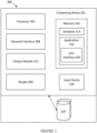
- FIG. 3 is a simplified block diagram of an exemplary computing system forming part of the systems of FIGS. 1A-2 , in accordance with one or more embodiments.
- computing system 300 may include computing device 301 and storage system 320.
- Storage system 320 may comprise a plurality of repositories and/or other forms of data storage, and it also may be in communication with computing device 301.
- storage system 320 which may comprise a plurality of repositories, may be housed in one or more of computing device 301.
- storage system 320 may store learned flight policies, as described herein, and other various types of information as described herein.
- Storage system 320 may comprise any type of computer storage, such as a hard-drive, memory card, ROM, RAM, DVD, CD-ROM, write-capable, and read-only memories.
- storage system 320 may include a distributed storage system where data is stored on a plurality of different storage devices, which may be physically located at the same or different geographic locations (e.g., in a distributed computing system such as system 400 in FIG. 4 ).
- Storage system 320 may be networked to computing device 301 directly using wired connections and/or wireless connections.
- Such network may include various configurations and protocols, including short range communication protocols such as Bluetooth TM , Bluetooth TM LE, the Internet, World Wide Web, intranets, virtual private networks, wide area networks, local networks, private networks using communication protocols proprietary to one or more companies, Ethernet, WiFi and HTTP, and various combinations of the foregoing.
- short range communication protocols such as Bluetooth TM , Bluetooth TM LE, the Internet, World Wide Web, intranets, virtual private networks, wide area networks, local networks, private networks using communication protocols proprietary to one or more companies, Ethernet, WiFi and HTTP, and various combinations of the foregoing.
- Such communication may be facilitated by any device capable of transmitting data to and from other computing devices, such as modems and wireless interfaces.
- Computing device 301 also may include a memory 302.
- Memory 302 may comprise a storage system configured to store a database 314 and an application 316.
- Application 316 may include instructions which, when executed by a processor 304, cause computing device 301 to perform various steps and/or functions, as described herein.
- Application 316 further includes instructions for generating a user interface 318 (e.g., graphical user interface (GUI)).
- Database 314 may store various algorithms and/or data, including neural networks (e.g., encoding flight policies, as described herein) and data regarding wind patterns, weather forecasts, past and present locations of aerial vehicles (e.g., aerial vehicles 120a-b, 201a-b, 211a-c), sensor data, map information, air traffic information, among other types of data.
- Memory 302 may include any non-transitory computer-readable storage medium for storing data and/or software that is executable by processor 304, and/or any other medium which may be used to store information that may be accessed by processor 304 to control the operation of computing device 301.
- Computing device 301 may further include a display 306, a network interface 308, an input device 310, and/or an output module 312.
- Display 306 may be any display device by means of which computing device 301 may output and/or display data.
- Network interface 308 may be configured to connect to a network using any of the wired and wireless short range communication protocols described above, as well as a cellular data network, a satellite network, free space optical network and/or the Internet.
- Input device 310 may be a mouse, keyboard, touch screen, voice interface, and/or any or other hand-held controller or device or interface by means of which a user may interact with computing device 301.
- Output module 312 may be a bus, port, and/or other interface by means of which computing device 301 may connect to and/or output data to other devices and/or peripherals.
- computing device 301 may be located remote from an aerial vehicle (e.g., aerial vehicles 120a-b, 201a-b, 211a-c) and may communicate with and/or control the operations of an aerial vehicle, or its control infrastructure as may be housed in avionics chassis 110a-b, via a network.
- computing device 301 is a data center or other control facility (e.g., configured to run a distributed computing system as described herein), and may communicate with a controller and/or flight computer housed in avionics chassis 110a-b via a network.
- system 300 may be used for planning a flight path or course for an aerial vehicle based on wind and weather forecasts to move said aerial vehicle along a desired heading or within a desired radius of a target location.
- Various configurations of system 300 are envisioned, and various steps and/or functions of the processes described below may be shared among the various devices of system 300, or may be assigned to specific devices.
- FIG. 4 is a simplified block diagram of an exemplary distributed computing system, in accordance with one or more embodiments, comprising two or more computing devices 301a-n.
- each of 301a-n may comprise one or more of processors 404a-n, respectively, and one or more of memory 402a-n, respectively.
- Processors 404a-n may function similarly to processor 304 in FIG. 3 , as described above.
- Memory 402a-n may function similarly to memory 302 in FIG. 3 , as described above.
- FIG. 5A is a diagram illustrating a group of aerial vehicles providing service coverage to a target service area according to winds favorable for station seeking, in accordance with one or more embodiments.
- service coverage may be for connectivity services, observing earth, and meteorological data collection, among other services.
- aerial vehicles 502-514 may be configured to provide wireless broadband, Internet, optical, or other connectivity services to areas that they may fly over, such as target service area 515 (i.e., and any wireless devices within), which may be within a given radius or perimeter of station 501.
- aerial vehicles 502-514 may be configured to observe various aspects of the portion of earth represented in, or collect meteorological data for, target service area 515, and to send the observation and meteorological data to station 501 or other network or ground station for storage and processing.
- station 501 may include a ground station, backhaul unit, or other ground infrastructure that may be in data communication with one or more of aerial vehicles 502-514, as described herein. Any two or more of aerial vehicles 502-514 may be in data communication with each other, as well as provide data connectivity to users in target service area 515, which may be a radius or perimeter around station 501.
- aerial vehicles 502-514 are shown over the same region of the atmosphere with arrows representing vectors along which aerial vehicles 502-514 are traveling within that time period, each vector corresponding to a wind direction and relative speed at a corresponding altitude.
- controllers for each of aerial vehicles 502-514 may be operating according to a station seeking flight policy.
- a station seeking flight policy may be a neural network encoding a flight policy optimizing for remaining within target service area 515 or other predetermined radius surrounding station 501.
- Said station seeking flight policy outputs a set of actions for one or more of aerial vehicles 502-514 to take, or a set of commands configured to cause an aerial vehicle to take certain actions, in order to remain within or near target service area 515.
- Example actions may include a change in altitude, a stay in altitude, a termination of flight (e.g., selective cut of balloon portion and/or layer, release of air or gas from a balloon or airship, etc.).
- Example commands may include spinning an ACS fan motor at a predetermined number of watts to increase or decrease density, changing a mode of operation (e.g., switching to a daytime or nighttime mode for one or more components of the aerial vehicle), changing a flight controller (e.g., in certain situations wherein the flight controller is not being assigned offboard), start/stop/change lateral propulsion (e.g., power setting on/off/increase/decrease for a fan, heading to point a fan, etc.), among other commands.
- a mode of operation e.g., switching to a daytime or nighttime mode for one or more components of the aerial vehicle
- a flight controller e.g., in certain situations wherein the flight controller is not being assigned offboard
- start/stop/change lateral propulsion e.g., power setting on/off/increase/decrease for a fan, heading to point a fan, etc.
- a station seeking flight policy may be a different type of system or model configured to select a heading and/or adjust an altitude of an aerial vehicle (e.g., one or more of aerial vehicles 502-514, or any other aerial vehicle described herein) based on input indicating a location and altitude of an aerial vehicle and wind pattern data regarding winds at a location and altitude of said aerial vehicle.
- a station seeking flight policy may be configured to determine a vector from a location of an aerial vehicle to a destination (e.g., a location at or within a target service location) and plan a path for the aerial vehicle based on the vector.
- the arrow next to aerial vehicle 502 indicates the vector (i.e., direction indicated by direction of arrowhead and relative speed indicated by a thickness of the arrow) that aerial vehicle 502 is traveling, the vector corresponding to a wind heading and relative speed at altitude Al.
- the controller may direct aerial vehicle 502 to change altitudes (e.g., to A2 or A3) to travel back into target service area 515 to continue providing connectivity services according to a connectivity service objective.
- altitude A2 aerial vehicles 504 and 506 are heading toward each other at similar speeds due to the countervailing winds at altitude A2.
- a controller for one or both of aerial vehicles 504 and 506 may direct either or both to change its altitude (e.g., to A1 or A4) to travel away from the other.
- the winds at altitude A3 blowing in a direction i.e., to the right
- aerial vehicle 508 is traveling in the direction at a higher speed.
- FIGS. 5B-5D are top down views of winds and aerial vehicles at various altitudes shown in FIG. 5A , in accordance with one or more embodiments.
- FIG. 5B on the right shows aerial vehicles 508 and 510 at altitude A3 in target service area 515, and on the left, the direction and relative magnitude of winds that are influencing the direction and relative speed of aerial vehicles 508 and 510, as well as direction and relative speed of other winds in target service area 515.
- aerial vehicles 512 and 514 are traveling at altitude A4 within target service area 515 in directions and relative speeds according to wind directions and relative speeds shown on the left.
- FIG. 5C shows aerial vehicles 508 and 510 at altitude A3 in target service area 515, and on the left, the direction and relative magnitude of winds that are influencing the direction and relative speed of aerial vehicles 508 and 510, as well as direction and relative speed of other winds in target service area 515.
- aerial vehicles 512 and 514 are traveling at altitude A4 within target service area 515 in directions and relative speeds
- aerial vehicles 504 and 506 are traveling at altitude A2 within target service area 515 in directions and relative speeds according to wind directions and relative speeds shown on the left.
- aerial vehicle 504 may get picked up by winds traveling in a slightly altered direction (e.g., toward the top right of page) once aerial vehicle 504 nears station 501, thus avoiding contact with aerial vehicle 506 without changing altitude.
- one or both of aerial vehicles 504 and 506 may be commanded to change altitude prior to reaching or crossing station 501 to change a direction and/or speed of travel.
- FIG. 6 is a diagram illustrating a group of aerial vehicles providing service coverage to a station according to winds not favorable for station seeking, in accordance with one or more embodiments.
- Aerial vehicles 602-614 may include the same or similar components and function similarly to aerial vehicles 502-514, but with respect to target service area 615 (i.e., and any wireless devices within), which may be within a given radius or perimeter of station 601.
- Station 601 may include similar components and function similarly to station 501.
- the winds in altitudes A1-A4 for a time period may all be blowing in the same direction, and thus not favorable for station seeking.
- a flight allocator or dispatcher system may deploy a larger number of vehicles to provide the same target level of coverage (i.e., the service coverage objective) in times of non-favorable station seeking winds, where a fewer number of vehicles might suffice in better station seeking winds.
- the system can automatically determine the number of vehicles that should be recruited to do so. For example, it may be determined, using techniques described herein, that aerial vehicles 602-614 cannot provide a minimum threshold probability of coverage to target service area 615 for the time period, due to the lack of variance in winds among and within altitudes A1-A4.
- controllers for aerial vehicles 602-614 may operate according to a different flight policy, such as one optimized for an aerial vehicle to travel across target service area 615, and to return to target service area 615 periodically.
- aerial vehicles 606 and 614 may be scheduled to arrive within target service area 615 and to provide connectivity services to target service area 615 on day 1.
- aerial vehicles 602 and 610 may be scheduled to arrive within target service area 615 on day 2, within a window of time before and/or after aerial vehicles 606 and 614 are leaving target service area 615.
- aerial vehicles 604 and 608 may be scheduled to arrive at target service area 615 later on day 2 to provide additional coverage (e.g., during a time period when there is an expectation of higher demand for connectivity services), or to take over providing connectivity services as aerial vehicles 606 and 614 are heading toward the opposite end of, or exiting, target service area 615.
- aerial vehicle 612 may be scheduled to arrive at target service area 615 on day 3.
- aerial vehicles 602-614 may avoid altitude A3 where the winds are stronger (i.e., faster), and where they would be blown out of target service area 615 at a faster rate, as this may shorten the period of time an aerial vehicle may provide connectivity services to target service area 615.
- one or more of aerial vehicles 602-614 may be directed or caused to travel in altitude A3 to avoid overcrowding at other altitudes.
- a flight policy may direct one or more of aerial vehicles 602-614 to loop back to target service area 615 every few days (e.g., a number of days less than or equal to N number of vehicles to ensure there always will be at least one aerial vehicle in service over target service area 615), such that this group of aerial vehicles 602-614 may continuously provide connectivity services to target service area 615.
- the loop back to target service area 615 may be a longer or shorter loop depending on one or more factors, including without limitation: the number of vehicles available, the service objective (e.g., a higher or lower level of desired coverage at different times of the day or different days of the week or month may mean at certain times more than one vehicle will be scheduled to provide coverage on the same day or with overlapping service time periods (e.g., when service demand is higher), and at other times it is ok to have a gap in service between a vehicle exiting target service area 615 and a vehicle entering target service area 615 (e.g., when service demand is lower)), the wind patterns (e.g., if winds are more uniform over a larger area, more vehicles may need to be provided to fly a farther loop to return to target service area 615; if winds are faster, more vehicles may need to be scheduled as each vehicle will be blown out of target service area 615 at a faster rate and thus each vehicle will provide service for a shorter period of time).
- the service objective e.g.,
- a service coverage planning system may switch back to station seeking based on a probabilistic approach when winds, and thus calculations of probabilities of coverage, change.
- a service coverage planning system also may switch back to a probabilistic approach where fewer vehicles are allocated to service target service area 615 (e.g., due to overall fleet availability, inability to dispatch more vehicles to the area at the appropriate times due to wind patterns elsewhere, and the like). Where a more limited group of vehicles are available to service target service area 615 in a scheduled loop as described above, there may be a lower probability of coverage threshold to meet in order for the system to choose station seeking over other methods.
- the group of aerial vehicles shown in FIGS. 5A-5D and FIG. 6 may be a homogeneous group of aerial vehicles comprising identical or nearly identical features and characteristics (e.g., they may all comprise balloons of the same size and shape in one example or all comprise a gliding vehicle of the same size and shape in another example, they may run the same or similar software, they may all have the same or similar hardware components, etc.).
- the group of aerial vehicles shown in FIGS. 5A-5D and FIG. 6 may be a heterogeneous group of aerial vehicles, including different types of lighter-than-air vehicles, as described in more detail above, and having different features and characteristics.
- a heterogeneous group of aerial vehicles may include a combination of balloons, airships, gliders, high altitude drones, or other high altitude aircraft, with differing methods of flight control on a spectrum from passive flight to powered propelled flight.
- some of the types of aerial vehicles in the heterogeneous group may be more costly to power and operate than other types of aerial vehicles in the heterogeneous group.
- the methods described herein may select a lower cost vehicle to perform a service coverage objective when the winds are favorable for station seeking by the lower cost vehicles.
- the systems described herein may allocate or dispatch higher cost vehicles (e.g., vehicles that are at least powered in part and are not wholly wind-driven) to perform the service coverage objective for that target location.
- higher cost vehicles e.g., vehicles that are at least powered in part and are not wholly wind-driven
- the aerial vehicles may still comprise non-interdependent vehicles (e.g., being launched or redirected from different locations at different times having differing probabilities of arriving at a target service area at different parts of a target time window by differing paths).
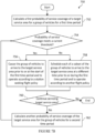
- FIG. 7A-7B are flow diagrams illustrating methods for providing service coverage by a group of aerial vehicles using a probabilistic approach, in accordance with one or more embodiments.
- method 700 begins with causing two or more aerial vehicles in a group to arrive at a target service area during an arrival time window associated with a connectivity service objective at step 702.
- the arrival time window may coincide with a service start date or time for the connectivity service objective, or with other timed aspects of the connectivity service objective.
- the connectivity service objective may include a desired probability of service coverage of the target service area.
- the connectivity service objective further may specify desired levels of service (e.g., based on historical, known, or anticipated demand for connectivity service), which may differ for different times of a day, days of a week or month, or other defined periods, and may include blackout periods where service is not desired.
- the connectivity service objective further may include secondary service objectives, such as exploring nearby service areas, gathering additional usage, weather, and other data for a target service area or nearby service areas, and other secondary objectives.
- a probability of service coverage of the target service area may be calculated for the two or more aerial vehicles for a first time period after the two or more vehicles are expected to arrive at the target service area at step 704.
- a determination may be made whether the probability of service coverage meets a desired probability of coverage threshold at step 706.
- the two or more vehicles may be caused to operate according to a station seeking flight policy during the first period of time at step 708.
- a separate determination may be made whether a forecasted wind pattern itself is favorable for station seeking, wherein the two or more vehicles may be controlled according to the station seeking flight policy in response to said determination based on the forecasted wind pattern, either in addition to or instead of the determination of the probability of service coverage meeting the desired probability of coverage threshold.
- a minimum number of additional vehicles necessary to meet the threshold may be determined, and one or more additional vehicles equal to said minimum number of additional vehicles may be caused to travel to the target service area to station seek.
- method 750 begins with calculating a first probability of service coverage of a target service area for a group of vehicles for a first time period at step 752.
- a determination may be made whether the probability of service coverage meets a current threshold probability of coverage at step 754.
- the threshold probability of coverage may be predetermined and unchanging. In other examples, the threshold probability of coverage may be dynamic based on factors described above, such as wind forecasts, determinations of whether a service objective may be met using other flight policies, and the like. If yes, the group of vehicles may be caused to arrive to the target service area prior to or at the start of the first time period and to operate according to a station seeking flight policy at step 756.
- each of a subset of the group of vehicles may be scheduled to arrive to the target service area at a different time prior to or during the first time period and to operate according to another (e.g., non-station seeking) flight policy at step 758.
- each of a subset of the group of vehicles may have a different arrival date or time window.
- a first subset may be scheduled to arrive at a date and/or time window and service the target service area for a given day or time period, until another subset of the group of vehicles is scheduled to arrive to the target service area.
- Said first subset may be scheduled to return (e.g., loop back) to the target service area after a certain other time period (e.g., a number of days, on a specified day in the future, within a specified time window each day for a number of days, etc.).
- a determination may be made whether to continue servicing the target service area at step 760. In some examples, this may involve determining whether a connectivity service objective has been completed or fulfilled. If yes, another probability of service coverage of the target service area may be calculated for the group of vehicles for a second time period at step 762, and the process may return to step 754 to determine whether this other probability of service calculation for the second time period meets the current threshold. If no, the process may terminate.
- the process may include a step (not shown) determining how many additional aerial vehicles may be needed to achieve the service coverage objective, and causing the determined number of additional vehicles needed to be deployed to the group.
- the process may include another step (not shown) wherein a first type of vehicle (e.g., lower cost, wind-driven) is selected to service the target service area when the probability of service coverage meets the current threshold, and a second type of vehicle (e.g., higher cost, powered and/or propelled) is selected to service the target service area when the probability of service coverage does not meet the current threshold.
- a first type of vehicle e.g., lower cost, wind-driven
- a second type of vehicle e.g., higher cost, powered and/or propelled
- time frames and ranges are illustrative, but one of ordinary skill in the art would understand that these time frames and ranges may be varied or even be dynamic and variable, depending on the implementation.
- Examples of computer-readable storage mediums include a read only memory (ROM), random-access memory (RAM), a register, cache memory, semiconductor memory devices, magnetic media such as internal hard disks and removable disks, magneto-optical media, and optical media such as CD-ROM disks.
- ROM read only memory
- RAM random-access memory
- register cache memory
- semiconductor memory devices magnetic media such as internal hard disks and removable disks, magneto-optical media, and optical media such as CD-ROM disks.
- Suitable processors include, by way of example, a general-purpose processor, a special purpose processor, a conventional processor, a digital signal processor (DSP), a plurality of microprocessors, one or more microprocessors in association with a DSP core, a controller, a microcontroller, Application Specific Integrated Circuits (ASICs), Field Programmable Gate Arrays (FPGAs) circuits, any other type of integrated circuit (IC), a state machine, or any combination of thereof.
- DSP digital signal processor
- ASICs Application Specific Integrated Circuits
- FPGAs Field Programmable Gate Arrays
Landscapes
- Engineering & Computer Science (AREA)
- Aviation & Aerospace Engineering (AREA)
- Physics & Mathematics (AREA)
- General Physics & Mathematics (AREA)
- Computer Networks & Wireless Communication (AREA)
- Signal Processing (AREA)
- Automation & Control Theory (AREA)
- Remote Sensing (AREA)
- Radar, Positioning & Navigation (AREA)
- Environmental & Geological Engineering (AREA)
- Astronomy & Astrophysics (AREA)
- Life Sciences & Earth Sciences (AREA)
- Atmospheric Sciences (AREA)
- Biodiversity & Conservation Biology (AREA)
- Ecology (AREA)
- Environmental Sciences (AREA)
- Traffic Control Systems (AREA)
- Mobile Radio Communication Systems (AREA)
Claims (15)
- Verfahren zum Steuern einer Gruppe von Leichter-als-Luft-Luftfahrzeugen (201a, 201b; 216a, 216b; 211a, 211b, 211c), die zumindest teilweise windgetrieben sind, um ein Konnektivitätsdienstziel zu erfüllen, wobei das Verfahren von einem Computergerät (301) durchgeführt wird, die sich entfernt von der Gruppe von Leichter-als-Luft-Luftfahrzeugen befindet, wobei das Verfahren umfasst:Veranlassen, dass zwei oder mehr Leichter-als-Luft-Luftfahrzeuge in der Gruppe während eines gegebenen Ankunftszeitfensters, das mit dem Konnektivitätsdienstziel verbunden ist, in einem Zielversorgungsgebiet (515) ankommen, wobei das Konnektivitätsdienstziel eine gewünschte Wahrscheinlichkeit der Dienstabdeckung des Zielversorgungsgebiets umfasst;Berechnen einer Wahrscheinlichkeit der Dienstabdeckung des Zielversorgungsgebiets für die zwei oder mehr Leichter-als-Luft-Luftfahrzeuge für einen ersten Zeitraum, nachdem erwartet wird, dass die zwei oder mehr Leichter-als-Luft-Luftfahrzeuge in dem Zielversorgungsgebiet eintreffen, wobei das Berechnen der Wahrscheinlichkeit der Dienstabdeckung beinhaltet:Ausführen von Einzelfahrzeugsimulationen der Flugbahnen jedes der zwei oder mehr Leichter-als-Luft-Fahrzeuge oder von Mehrfahrzeugsimulationen der Flugbahnen der zwei oder mehr Leichter-als-Luft-Fahrzeuge, um die Wahrscheinlichkeit der Dienstabdeckung des Zielversorgungsgebiets für die zwei oder mehr Leichter-als-Luft-Luftfahrzeuge für einen ersten Zeitraum zu bestimmen, wobei die Simulationen auf den Eigenschaften der Leichter-als-Luft-Luftfahrzeuge und den vorhergesagten Windmustern für den ersten Zeitraum in dem Zielversorgungsgebiet basieren, oderBestimmen, direkt basierend auf den vorhergesagten Windmustern für den ersten Zeitraum in dem Zielversorgungsgebiet, ob die vorhergesagten Windmuster für die Stationssuche günstig sind, um daraus die Wahrscheinlichkeit der Dienstabdeckung des Zielversorgungsgebietes für die zwei oder mehr Leichter-als-Luft-Luftfahrzeuge für einen ersten Zeitraum abzuleiten;Bestimmen, ob die Wahrscheinlichkeit der Dienstabdeckung einen Schwellenwert für die Wahrscheinlichkeit der Abdeckung erfüllt; undwenn die Wahrscheinlichkeit der Dienstabdeckung den Schwellenwert für die Wahrscheinlichkeit der Abdeckung erreicht, veranlassen, dass die zwei oder mehr Leichter-als-Luft-Luftfahrzeuge während des ersten Zeitraums unabhängig voneinander gemäß einerStationssuchflugrichtlinie betrieben werden, wobei die Stationssuchflugrichtlinie a) einen Satz von durchzuführenden Aktionen für das Leichter-als-Luft-Luftfahrzeug ausgibt, um für den ersten Zeitraum in dem oder in der Nähe des Zielversorgungsgebiets zu verbleiben, und/oder b) einen Satz von Befehlen ausgibt, die zum Veranlassen des Leichter-als-Luft-Luftfahrzeugs ausgelegt sind, eine oder mehrere Aktionen durchzuführen, um für den ersten Zeitraum in dem oder in der Nähe des Zielversorgungsgebiets zu verbleiben.
- Verfahren nach einem der vorhergehenden Ansprüche, wobei das Konnektivitätsdienstziel ein gewünschtes Dienstniveau spezifiziert, und wobei das gewünschte Dienstniveau optional auf einer Nachfrage nach Konnektivitätsdiensten basiert.
- Verfahren nach einem der vorhergehenden Ansprüche, wobei das Veranlassen der zwei oder mehr Leichter-als-Luft-Luftfahrzeuge, gemäß der Stationssuchflugrichtlinie zu arbeiten, in Reaktion auf eine Bestimmung erfolgt, dass die Wahrscheinlichkeit der Dienstabdeckung den Schwellenwert für die Wahrscheinlichkeit der Abdeckung erfüllt.
- Verfahren nach einem der vorhergehenden Ansprüche, ferner umfassend das Bestimmen, ob ein vorhergesagtes Windmuster für die Stationssuche günstig ist, wobei das Veranlassen der zwei oder mehr Leichter-als-Luft-Luftfahrzeuge gemäß der Stationssuchflugrichtlinie zu arbeiten, in Reaktion auf die Bestimmung erfolgt, dass das vorhergesagte Windmuster für die Stationssuche günstig ist.
- Verfahren nach einem der vorhergehenden Ansprüche, ferner umfassend:
wenn die Wahrscheinlichkeit der Dienstabdeckung den Schwellenwert für die Wahrscheinlichkeit der Abdeckung nicht erreicht:Berechnen einer Mindestanzahl zusätzlicher Leichter-als-Luft-Luftfahrzeuge, die erforderlich ist, um den Schwellenwert für die Wahrscheinlichkeit der Abdeckung zu erfüllen;Veranlassen eines oder mehrerer zusätzlicher Leichter-als-Luft-Luftfahrzeuge, die der Mindestanzahl zusätzlicher Leichter-als-Luft-Luftfahrzeuge entsprechen, zu dem Zielversorgungsgebiet zu fliegen; undVeranlassen des einen oder der mehreren zusätzlichen Leichter-als-Luft-Luftfahrzeuge, während des verbleibenden Teils des ersten Zeitraums gemäß einer Stationssuchflugrichtlinie zu arbeiten. - Verfahren nach einem der Ansprüche 1 bis 4, ferner umfassend:
wenn die Wahrscheinlichkeit der Dienstabdeckung den Schwellenwert für die Wahrscheinlichkeit der Abdeckung nicht erreicht, Planen für individuelle Leichter-als-Luft-Luftfahrzeuge, das Zielgebiet für bestimmte Abschnitte des ersten Zeitraums zu versorgen. - Verfahren nach einem der vorhergehenden Ansprüche, wobei die Gruppe der Leichter-als-Luft-Luftfahrzeuge zwei oder mehr heterogene Leichter-als-Luft-Luftfahrzeuge umfasst, und/oder wobei die Gruppe der Leichter-als-Luft-Luftfahrzeuge zwei oder mehr nicht voneinander abhängige Leichter-als-Luft-Luftfahrzeuge umfasst und/oder wobei die Gruppe der Leichter-als-Luft-Luftfahrzeuge zumindest einen Ballon (211a) umfasst.
- Verfahren nach einem der vorhergehenden Ansprüche, wobei die Gruppe der Leichter-als-Luft-Luftfahrzeuge zumindest ein Starrflügel-Leichter-als-Luft-Luftfahrzeug für hohe Höhen (211c)umfasst.
- Verfahren nach einem der vorhergehenden Ansprüche, wobei sich das gegebene Ankunftszeitfenster mit einem durch das Konnektivitätsdienstziel spezifizierten Beginn des Konnektivitätsdienstes überschneidet, und/oder wobei sich der erste Zeitraum mit dem gegebenen Ankunftszeitfenster überschneidet.
- Verfahren nach einem der vorhergehenden Ansprüche, wobei die Stationssuchflugrichtlinie ein neuronales Netzwerk umfasst, das eine Flugrichtlinie kodiert, die das Verbleiben in dem Zielversorgungsgebiet für einen ersten Zeitraum optimiert.
- Verfahren nach einem vorhergehenden Anspruch, wobei die Stationssuchflugrichtlinie zum Auswählen eines Kurses basierend auf einer Eingabe ausgelegt ist, die anzeigt:einen Standort und eine Höhe von jedem der zwei oder mehr Leichter-als-Luft-Luftfahrzeuge, Windmusterdaten für den Standort und die Höhe, undein Ziel, wobei das Ziel mit dem Zielversorgungsgebiet assoziiert ist; und/oder, wobei dieStationssuchflugrichtlinie zum Anpassen einer Höhe von jedem der zwei oder mehr Leichter-als-Luft-Luftfahrzeuge ausgelegt ist.
- Verfahren nach einem der vorhergehenden Ansprüche, ferner umfassend:Auswählen einer Untergruppe kostengünstigerer Leichter-als-Luft-Luftfahrzeuge zum Versorgen des Zielversorgungsgebiets basierend auf einer Bestimmung, dass die Wahrscheinlichkeit der Dienstabdeckung durch die Untergruppe kostengünstiger Leichter-als-Luft-Luftfahrzeuge den Schwellenwert für die Wahrscheinlichkeit der Abdeckung für einen zweiten Zeitraum erfüllt; undVeranlassen der Untergruppe der kostengünstigeren Leichter-als-Luft-Luftfahrzeuge, das Zielversorgungsgebiet für einen zweiten Zeitraum zu versorgen,wobei die Gruppe der Leichter-als-Luft-Luftfahrzeuge eine heterogene Gruppe von Leichter-als-Luft-Luftfahrzeugen umfasst.
- Verfahren nach einem der Ansprüche 1 bis 11, ferner umfassend:Auswählen einer Untergruppe von teureren Leichter-als-Luft-Luftfahrzeugen zum Versorgen des Zielversorgungsgebiets basierend auf einer Bestimmung, dass die Wahrscheinlichkeit der Dienstabdeckung durch eine Untergruppe von kostengünstigeren Leichter-als-Luft-Luftfahrzeugen den Schwellenwert für die Wahrscheinlichkeit der Abdeckung für einen zweiten Zeitraum nicht erfüllt; undVeranlassen der Untergruppe der teureren Leichter-als-Luft-Luftfahrzeuge, das Zielversorgungsgebiet für den zweiten Zeitraum zu versorgen,wobei die Gruppe der Leichter-als-Luft-Luftfahrzeuge eine heterogene Gruppe von Leichter-als-Luft-Luftfahrzeugen umfasst.
- Verfahren nach einem der vorhergehenden Ansprüche, wobei das vorgegebene Ankunftszeitfenster mit einem Datum oder einer Uhrzeit für den Dienstbeginn des Konnektivitätsdienstziels übereinstimmt und das Konnektivitätsdienstziel gewünschte Dienstniveaus spezifiziert, die sich für verschiedene Tageszeiten und Zeiträume unterscheiden, wobei die Zeiträume Sperrzeiten beinhalten, in denen kein Dienst erwünscht ist.
- Computersystem, umfassend:einen Speicher; undeinen oder mehrere Prozessoren, die zum Durchführen von Operationen zum Steuern einer Gruppe von Leichter-als-Luft-Luftfahrzeugen (201a, 201b; 216a, 216b; 211a, 211b, 211c) ausgelegt sind, um ein Konnektivitätsdienstziel zu erfüllen,wobei der eine oder die mehreren Prozessoren zum Durchführen des Verfahrens nach einem der Ansprüche 1 bis 14 ausgelegt sind.
Applications Claiming Priority (2)
| Application Number | Priority Date | Filing Date | Title |
|---|---|---|---|
| US16/728,771 US11281206B2 (en) | 2019-12-27 | 2019-12-27 | Delivering connectivity to a service area by aerial vehicles using probabilistic methods |
| PCT/US2020/063800 WO2021133544A1 (en) | 2019-12-27 | 2020-12-08 | Delivering connectivity to a service area by aerial vehicles using probabilistic methods |
Publications (3)
| Publication Number | Publication Date |
|---|---|
| EP4046404A1 EP4046404A1 (de) | 2022-08-24 |
| EP4046404B1 true EP4046404B1 (de) | 2024-01-17 |
| EP4046404C0 EP4046404C0 (de) | 2024-01-17 |
Family
ID=74068690
Family Applications (1)
| Application Number | Title | Priority Date | Filing Date |
|---|---|---|---|
| EP20829758.0A Active EP4046404B1 (de) | 2019-12-27 | 2020-12-08 | Bereitstellung von konnektivität für einen dienstbereich durch luftfahrzeuge mit probabilistischen methoden |
Country Status (4)
| Country | Link |
|---|---|
| US (1) | US11281206B2 (de) |
| EP (1) | EP4046404B1 (de) |
| JP (1) | JP7405977B2 (de) |
| WO (1) | WO2021133544A1 (de) |
Families Citing this family (4)
| Publication number | Priority date | Publication date | Assignee | Title |
|---|---|---|---|---|
| US11451980B2 (en) * | 2020-06-24 | 2022-09-20 | T-Mobile Usa, Inc. | Communication to under-served areas using communication enabled vehicles |
| US20220114506A1 (en) * | 2020-10-12 | 2022-04-14 | Joby Elevate, Inc. | Systems and Methods for Optimizing Multi-Modal Transportation |
| US11811486B2 (en) * | 2021-06-29 | 2023-11-07 | At&T Intellectual Property I, L.P. | System and methods to provide aerial backhaul connectivity to terrestrial base stations |
| US20250284703A1 (en) * | 2024-03-08 | 2025-09-11 | Capital One Services, Llc | Communicating via a communication channel identified from an extract, transform, and load process |
Family Cites Families (12)
| Publication number | Priority date | Publication date | Assignee | Title |
|---|---|---|---|---|
| WO2005081680A2 (en) * | 2003-09-09 | 2005-09-09 | Universtiy Of Massachusetts | System and method for altitude control |
| US20110147513A1 (en) * | 2009-01-21 | 2011-06-23 | John Steven Surmont | Aerial payload deployment system |
| US9489845B2 (en) * | 2011-04-08 | 2016-11-08 | Fleetmatics Development Limited | System and method for providing vehicle and fleet profiles and presentations of trends |
| US9014957B2 (en) * | 2012-12-29 | 2015-04-21 | Google Inc. | Methods and systems for determining fleet trajectories to satisfy a sequence of coverage requirements |
| US9635706B1 (en) * | 2013-01-02 | 2017-04-25 | X Development Llc | Method for determining fleet control policies to satisfy a sequence of coverage requirements |
| US9628395B1 (en) * | 2013-06-05 | 2017-04-18 | X Development Llc | Interfaces for service requests in a balloon network |
| US10657827B2 (en) | 2015-12-09 | 2020-05-19 | Dronesense Llc | Drone flight operations |
| US10395542B2 (en) | 2016-03-28 | 2019-08-27 | Cisco Technology, Inc. | Drone traffic engineering |
| CN109862580B (zh) | 2017-11-30 | 2020-12-15 | 华为技术有限公司 | 一种网络优化方法及装置 |
| US10894601B2 (en) | 2017-12-20 | 2021-01-19 | Wing Aviation Llc | Methods and systems for self-deployment of operational infrastructure by an unmanned aerial vehicle (UAV) |
| US10419946B1 (en) * | 2018-03-07 | 2019-09-17 | Loon Llc | Systems and methods for planning high altitude platform-based communication networks |
| US11015935B2 (en) * | 2018-12-17 | 2021-05-25 | Loon Llc | Wind data based flight maps for aircraft |
-
2019
- 2019-12-27 US US16/728,771 patent/US11281206B2/en active Active
-
2020
- 2020-12-08 EP EP20829758.0A patent/EP4046404B1/de active Active
- 2020-12-08 WO PCT/US2020/063800 patent/WO2021133544A1/en not_active Ceased
- 2020-12-08 JP JP2022530317A patent/JP7405977B2/ja active Active
Also Published As
| Publication number | Publication date |
|---|---|
| EP4046404C0 (de) | 2024-01-17 |
| JP7405977B2 (ja) | 2023-12-26 |
| JP2023515739A (ja) | 2023-04-14 |
| US20210200204A1 (en) | 2021-07-01 |
| WO2021133544A1 (en) | 2021-07-01 |
| EP4046404A1 (de) | 2022-08-24 |
| US11281206B2 (en) | 2022-03-22 |
Similar Documents
| Publication | Publication Date | Title |
|---|---|---|
| US20210123741A1 (en) | Systems and Methods for Navigating Aerial Vehicles Using Deep Reinforcement Learning | |
| EP4046404B1 (de) | Bereitstellung von konnektivität für einen dienstbereich durch luftfahrzeuge mit probabilistischen methoden | |
| US20210124352A1 (en) | Systems and Methods for Navigating Aerial Vehicles Using Deep Reinforcement Learning | |
| US12148311B2 (en) | Systems and methods for managing energy use in automated vehicles | |
| US20210181768A1 (en) | Controllers for Lighter-Than-Air (LTA) Vehicles Using Deep Reinforcement Learning | |
| WO2021086532A1 (en) | Navigating aerial vehicles using deep reinforcement learning | |
| US9959771B1 (en) | Unmanned aerial vehicle routing using real-time weather data | |
| CN114785408B (zh) | 一种基于资源分配和轨迹优化的无人机辅助通信方法 | |
| WO2021194612A1 (en) | Service dispatcher for fleet management and flight planning system | |
| US20210304627A1 (en) | Recovery and Test Dispatchers for Fleet Management and Flight Planning Systems | |
| JP7638901B2 (ja) | 高空域長期滞空航空機の飛行計画最適化のための方法とシステム | |
| US20210335137A1 (en) | Dynamic Risk Assessment of a Fleet of Aircraft | |
| WO2019058991A1 (ja) | 気流データを利用したhaps飛行制御 | |
| US20220203841A1 (en) | Managing Nighttime Power for Solar-Powered Vehicles | |
| JP7466007B2 (ja) | 動的ハイブリッドネットワークのシミュレーション | |
| US20220276662A1 (en) | Real-time Vehicle State Estimation and Sensor Management | |
| WO2021133543A1 (en) | Dynamic unmanned aircraft fleet issue management | |
| JP2026058129A (ja) | 通信システム、通信制御方法およびプログラム | |
| US20220276055A1 (en) | Aerial Vehicle Launch and Land Site Selection | |
| US20220207932A1 (en) | Lighter-than-air (LTA) Vehicle Health and Lifetime Estimation | |
| JP7520155B2 (ja) | メタマテリアルの縁部を有する球面反射器を含むアンテナシステム | |
| US20210344215A1 (en) | Power Saving Modes for Subsystems in Solar Powered Aircraft | |
| EP3933534A1 (de) | Systeme und verfahren zur verwaltung des energieverbrauchs in automatisierten fahrzeugen | |
| CN117993475A (zh) | 一种基于深度强化学习的能量效率无人机资源调度方法 | |
| US20220169358A1 (en) | LTA Vehicle Launch Configuration and In-Flight Optimization |
Legal Events
| Date | Code | Title | Description |
|---|---|---|---|
| STAA | Information on the status of an ep patent application or granted ep patent |
Free format text: STATUS: UNKNOWN |
|
| STAA | Information on the status of an ep patent application or granted ep patent |
Free format text: STATUS: THE INTERNATIONAL PUBLICATION HAS BEEN MADE |
|
| PUAI | Public reference made under article 153(3) epc to a published international application that has entered the european phase |
Free format text: ORIGINAL CODE: 0009012 |
|
| STAA | Information on the status of an ep patent application or granted ep patent |
Free format text: STATUS: REQUEST FOR EXAMINATION WAS MADE |
|
| 17P | Request for examination filed |
Effective date: 20220517 |
|
| AK | Designated contracting states |
Kind code of ref document: A1 Designated state(s): AL AT BE BG CH CY CZ DE DK EE ES FI FR GB GR HR HU IE IS IT LI LT LU LV MC MK MT NL NO PL PT RO RS SE SI SK SM TR |
|
| STAA | Information on the status of an ep patent application or granted ep patent |
Free format text: STATUS: EXAMINATION IS IN PROGRESS |
|
| 17Q | First examination report despatched |
Effective date: 20230224 |
|
| DAV | Request for validation of the european patent (deleted) | ||
| DAX | Request for extension of the european patent (deleted) | ||
| REG | Reference to a national code |
Ref country code: DE Free format text: PREVIOUS MAIN CLASS: H04W0004440000 Ref country code: DE Ref legal event code: R079 Ref document number: 602020024608 Country of ref document: DE Free format text: PREVIOUS MAIN CLASS: H04W0004440000 Ipc: H04W0016260000 |
|
| RIC1 | Information provided on ipc code assigned before grant |
Ipc: H04W 84/06 20090101ALI20230718BHEP Ipc: H04W 16/18 20090101ALI20230718BHEP Ipc: H04B 7/185 20060101ALI20230718BHEP Ipc: H04W 24/02 20090101ALI20230718BHEP Ipc: H04W 4/44 20180101ALI20230718BHEP Ipc: H04W 16/26 20090101AFI20230718BHEP |
|
| GRAP | Despatch of communication of intention to grant a patent |
Free format text: ORIGINAL CODE: EPIDOSNIGR1 |
|
| STAA | Information on the status of an ep patent application or granted ep patent |
Free format text: STATUS: GRANT OF PATENT IS INTENDED |
|
| INTG | Intention to grant announced |
Effective date: 20230911 |
|
| GRAS | Grant fee paid |
Free format text: ORIGINAL CODE: EPIDOSNIGR3 |
|
| GRAA | (expected) grant |
Free format text: ORIGINAL CODE: 0009210 |
|
| STAA | Information on the status of an ep patent application or granted ep patent |
Free format text: STATUS: THE PATENT HAS BEEN GRANTED |
|
| AK | Designated contracting states |
Kind code of ref document: B1 Designated state(s): AL AT BE BG CH CY CZ DE DK EE ES FI FR GB GR HR HU IE IS IT LI LT LU LV MC MK MT NL NO PL PT RO RS SE SI SK SM TR |
|
| REG | Reference to a national code |
Ref country code: GB Ref legal event code: FG4D |
|
| REG | Reference to a national code |
Ref country code: DE Ref legal event code: R096 Ref document number: 602020024608 Country of ref document: DE |
|
| REG | Reference to a national code |
Ref country code: CH Ref legal event code: EP |
|
| REG | Reference to a national code |
Ref country code: IE Ref legal event code: FG4D |
|
| U01 | Request for unitary effect filed |
Effective date: 20240117 |
|
| U07 | Unitary effect registered |
Designated state(s): AT BE BG DE DK EE FI FR IT LT LU LV MT NL PT SE SI Effective date: 20240131 |
|
| PG25 | Lapsed in a contracting state [announced via postgrant information from national office to epo] |
Ref country code: IS Free format text: LAPSE BECAUSE OF FAILURE TO SUBMIT A TRANSLATION OF THE DESCRIPTION OR TO PAY THE FEE WITHIN THE PRESCRIBED TIME-LIMIT Effective date: 20240517 |
|
| PG25 | Lapsed in a contracting state [announced via postgrant information from national office to epo] |
Ref country code: GR Free format text: LAPSE BECAUSE OF FAILURE TO SUBMIT A TRANSLATION OF THE DESCRIPTION OR TO PAY THE FEE WITHIN THE PRESCRIBED TIME-LIMIT Effective date: 20240418 |
|
| PG25 | Lapsed in a contracting state [announced via postgrant information from national office to epo] |
Ref country code: RS Free format text: LAPSE BECAUSE OF FAILURE TO SUBMIT A TRANSLATION OF THE DESCRIPTION OR TO PAY THE FEE WITHIN THE PRESCRIBED TIME-LIMIT Effective date: 20240417 Ref country code: HR Free format text: LAPSE BECAUSE OF FAILURE TO SUBMIT A TRANSLATION OF THE DESCRIPTION OR TO PAY THE FEE WITHIN THE PRESCRIBED TIME-LIMIT Effective date: 20240117 |
|
| PG25 | Lapsed in a contracting state [announced via postgrant information from national office to epo] |
Ref country code: ES Free format text: LAPSE BECAUSE OF FAILURE TO SUBMIT A TRANSLATION OF THE DESCRIPTION OR TO PAY THE FEE WITHIN THE PRESCRIBED TIME-LIMIT Effective date: 20240117 |
|
| PG25 | Lapsed in a contracting state [announced via postgrant information from national office to epo] |
Ref country code: RS Free format text: LAPSE BECAUSE OF FAILURE TO SUBMIT A TRANSLATION OF THE DESCRIPTION OR TO PAY THE FEE WITHIN THE PRESCRIBED TIME-LIMIT Effective date: 20240417 Ref country code: NO Free format text: LAPSE BECAUSE OF FAILURE TO SUBMIT A TRANSLATION OF THE DESCRIPTION OR TO PAY THE FEE WITHIN THE PRESCRIBED TIME-LIMIT Effective date: 20240417 Ref country code: IS Free format text: LAPSE BECAUSE OF FAILURE TO SUBMIT A TRANSLATION OF THE DESCRIPTION OR TO PAY THE FEE WITHIN THE PRESCRIBED TIME-LIMIT Effective date: 20240517 Ref country code: HR Free format text: LAPSE BECAUSE OF FAILURE TO SUBMIT A TRANSLATION OF THE DESCRIPTION OR TO PAY THE FEE WITHIN THE PRESCRIBED TIME-LIMIT Effective date: 20240117 Ref country code: GR Free format text: LAPSE BECAUSE OF FAILURE TO SUBMIT A TRANSLATION OF THE DESCRIPTION OR TO PAY THE FEE WITHIN THE PRESCRIBED TIME-LIMIT Effective date: 20240418 Ref country code: ES Free format text: LAPSE BECAUSE OF FAILURE TO SUBMIT A TRANSLATION OF THE DESCRIPTION OR TO PAY THE FEE WITHIN THE PRESCRIBED TIME-LIMIT Effective date: 20240117 |
|
| PG25 | Lapsed in a contracting state [announced via postgrant information from national office to epo] |
Ref country code: PL Free format text: LAPSE BECAUSE OF FAILURE TO SUBMIT A TRANSLATION OF THE DESCRIPTION OR TO PAY THE FEE WITHIN THE PRESCRIBED TIME-LIMIT Effective date: 20240117 |
|
| PG25 | Lapsed in a contracting state [announced via postgrant information from national office to epo] |
Ref country code: PL Free format text: LAPSE BECAUSE OF FAILURE TO SUBMIT A TRANSLATION OF THE DESCRIPTION OR TO PAY THE FEE WITHIN THE PRESCRIBED TIME-LIMIT Effective date: 20240117 |
|
| PG25 | Lapsed in a contracting state [announced via postgrant information from national office to epo] |
Ref country code: SM Free format text: LAPSE BECAUSE OF FAILURE TO SUBMIT A TRANSLATION OF THE DESCRIPTION OR TO PAY THE FEE WITHIN THE PRESCRIBED TIME-LIMIT Effective date: 20240117 |
|
| REG | Reference to a national code |
Ref country code: DE Ref legal event code: R097 Ref document number: 602020024608 Country of ref document: DE |
|
| PG25 | Lapsed in a contracting state [announced via postgrant information from national office to epo] |
Ref country code: CZ Free format text: LAPSE BECAUSE OF FAILURE TO SUBMIT A TRANSLATION OF THE DESCRIPTION OR TO PAY THE FEE WITHIN THE PRESCRIBED TIME-LIMIT Effective date: 20240117 |
|
| PG25 | Lapsed in a contracting state [announced via postgrant information from national office to epo] |
Ref country code: SK Free format text: LAPSE BECAUSE OF FAILURE TO SUBMIT A TRANSLATION OF THE DESCRIPTION OR TO PAY THE FEE WITHIN THE PRESCRIBED TIME-LIMIT Effective date: 20240117 |
|
| PG25 | Lapsed in a contracting state [announced via postgrant information from national office to epo] |
Ref country code: SM Free format text: LAPSE BECAUSE OF FAILURE TO SUBMIT A TRANSLATION OF THE DESCRIPTION OR TO PAY THE FEE WITHIN THE PRESCRIBED TIME-LIMIT Effective date: 20240117 Ref country code: SK Free format text: LAPSE BECAUSE OF FAILURE TO SUBMIT A TRANSLATION OF THE DESCRIPTION OR TO PAY THE FEE WITHIN THE PRESCRIBED TIME-LIMIT Effective date: 20240117 Ref country code: RO Free format text: LAPSE BECAUSE OF FAILURE TO SUBMIT A TRANSLATION OF THE DESCRIPTION OR TO PAY THE FEE WITHIN THE PRESCRIBED TIME-LIMIT Effective date: 20240117 Ref country code: CZ Free format text: LAPSE BECAUSE OF FAILURE TO SUBMIT A TRANSLATION OF THE DESCRIPTION OR TO PAY THE FEE WITHIN THE PRESCRIBED TIME-LIMIT Effective date: 20240117 |
|
| PLBE | No opposition filed within time limit |
Free format text: ORIGINAL CODE: 0009261 |
|
| STAA | Information on the status of an ep patent application or granted ep patent |
Free format text: STATUS: NO OPPOSITION FILED WITHIN TIME LIMIT |
|
| 26N | No opposition filed |
Effective date: 20241018 |
|
| U20 | Renewal fee for the european patent with unitary effect paid |
Year of fee payment: 5 Effective date: 20241216 |
|
| PG25 | Lapsed in a contracting state [announced via postgrant information from national office to epo] |
Ref country code: MC Free format text: LAPSE BECAUSE OF FAILURE TO SUBMIT A TRANSLATION OF THE DESCRIPTION OR TO PAY THE FEE WITHIN THE PRESCRIBED TIME-LIMIT Effective date: 20240117 |
|
| REG | Reference to a national code |
Ref country code: CH Ref legal event code: PL |
|
| PG25 | Lapsed in a contracting state [announced via postgrant information from national office to epo] |
Ref country code: CH Free format text: LAPSE BECAUSE OF NON-PAYMENT OF DUE FEES Effective date: 20241231 |
|
| PG25 | Lapsed in a contracting state [announced via postgrant information from national office to epo] |
Ref country code: IE Free format text: LAPSE BECAUSE OF NON-PAYMENT OF DUE FEES Effective date: 20241208 |
|
| U20 | Renewal fee for the european patent with unitary effect paid |
Year of fee payment: 6 Effective date: 20251110 |
|
| PGFP | Annual fee paid to national office [announced via postgrant information from national office to epo] |
Ref country code: GB Payment date: 20251030 Year of fee payment: 6 |