EP4045718B1 - Aufpralldämpfer - Google Patents
Aufpralldämpfer Download PDFInfo
- Publication number
- EP4045718B1 EP4045718B1 EP20876431.6A EP20876431A EP4045718B1 EP 4045718 B1 EP4045718 B1 EP 4045718B1 EP 20876431 A EP20876431 A EP 20876431A EP 4045718 B1 EP4045718 B1 EP 4045718B1
- Authority
- EP
- European Patent Office
- Prior art keywords
- crash attenuator
- holes
- center rail
- attenuator
- crash
- Prior art date
- Legal status (The legal status is an assumption and is not a legal conclusion. Google has not performed a legal analysis and makes no representation as to the accuracy of the status listed.)
- Active
Links
Images

Classifications
-
- E—FIXED CONSTRUCTIONS
- E01—CONSTRUCTION OF ROADS, RAILWAYS, OR BRIDGES
- E01F—ADDITIONAL WORK, SUCH AS EQUIPPING ROADS OR THE CONSTRUCTION OF PLATFORMS, HELICOPTER LANDING STAGES, SIGNS, SNOW FENCES, OR THE LIKE
- E01F15/00—Safety arrangements for slowing, redirecting or stopping errant vehicles, e.g. guard posts or bollards; Arrangements for reducing damage to roadside structures due to vehicular impact
- E01F15/02—Continuous barriers extending along roads or between traffic lanes
- E01F15/04—Continuous barriers extending along roads or between traffic lanes essentially made of longitudinal beams or rigid strips supported above ground at spaced points
- E01F15/0407—Metal rails
- E01F15/0423—Details of rails
-
- E—FIXED CONSTRUCTIONS
- E01—CONSTRUCTION OF ROADS, RAILWAYS, OR BRIDGES
- E01F—ADDITIONAL WORK, SUCH AS EQUIPPING ROADS OR THE CONSTRUCTION OF PLATFORMS, HELICOPTER LANDING STAGES, SIGNS, SNOW FENCES, OR THE LIKE
- E01F15/00—Safety arrangements for slowing, redirecting or stopping errant vehicles, e.g. guard posts or bollards; Arrangements for reducing damage to roadside structures due to vehicular impact
- E01F15/14—Safety arrangements for slowing, redirecting or stopping errant vehicles, e.g. guard posts or bollards; Arrangements for reducing damage to roadside structures due to vehicular impact specially adapted for local protection, e.g. for bridge piers, for traffic islands
- E01F15/145—Means for vehicle stopping using impact energy absorbers
- E01F15/146—Means for vehicle stopping using impact energy absorbers fixed arrangements
Definitions
- the present invention relates generally to crash impact attenuators, and more particularly to motor vehicle and highway barrier crash impact attenuators comprising fixed systems protecting leading edges of abutments and other fixed roadside hazards.
- a prior art crash attenuator is known from EP 1 706 544 B1 .
- a crash attenuator of the type described must absorb the vehicle impact energy without exceeding limits on the vehicle deceleration. In addition, it must accommodate both heavy and light weight vehicles. The lightest vehicle will set the limit on the maximum force produced by the attenuator and the heavy vehicle - which will experience a lower deceleration, and thus will determine the total impact deformation required. The force cannot exceed the light vehicle limit and therefore the initial force and deceleration is low, limiting the energy absorption. Increasing crash resistance as the vehicle "rides down" from its impact speed to zero is a vitally important feature of a crash attenuator system which meets rigid governmental safety standards. The present invention accomplishes this objective in an innovative, inexpensive, and very simple, but effective, manner.
- the present invention comprises, in one exemplary aspect, a crash attenuator system for deployment in front of a fixed structure, such as a bridge abutment.
- the system comprises a rail extending along a length of the crash attenuator system, a plurality of diaphragms initially disposed in spaced relation along the length of the rail, each of the plurality of diaphragms having a base end adapted to be movably engaged with the rail, so that when a front end of the crash attenuator system receives an impact force from an errant vehicle, a first one of the plurality of diaphragms moves rearwardly along the rail and impacts a second one of the plurality of diaphragms so that both the first and second ones of the plurality of diaphragms move further rearwardly along the rail, this process continuing with additional ones of the plurality of diaphragms until the impact forces have been fully attenuated.
- the system further comprises a tearing member on the crash attenuator system which is adapted to engage material forming a tearable member of the crash attenuator system, the tearing member and the tearable member being relatively movable when an impact force strikes the crash attenuator system so that the tearing member tears the tearable member, thereby increasing attenuation of the impact force.
- the tearing member comprises a bolt, and is disposed on one of the plurality of diaphragms, such as on a base end of the first one of the plurality of diaphragms.
- the tearing member may comprise a plurality of tearing members.
- the center rail extends along at least a portion of the length of the crash attenuator and includes a plurality of holes disposed therein, the plurality of holes extending along a length of the center rail and spaced lengthwise from one another.
- the bolt is engaged with one of the plurality of holes so that when an impact force is applied to the crash attenuator, relative motion occurs between the tearable member and the tearing member so that the relative motion causes the bolt to tear the material between adjacent ones of the plurality of holes, thereby creating a continuous slot, the tearing of the material functioning to attenuate the impact force.
- the holes are not evenly spaced along the length of the tearable member having the plurality of holes disposed therein.
- adjacent ones of the plurality of holes nearer to one of the front and back ends of the crash attenuator may be more closely spaced than adjacent ones of the plurality of holes closer to the other of the front and back ends of the crash attenuator.
- the plurality of holes are not uniform in size, respective to one another.
- the frontmost ones of the plurality of holes may be larger and more elongated than those of the plurality of holes which are located closer to the back end of the crash attenuator, though the directional orientation may be reversed depending upon application and desired attenuation characteristics.
- the material forming the tearable member may be thinner toward one of the front and back ends of the crash attenuator, and thicker toward the other of the front and back ends of the crash attenuator.
- the tearable member may comprise a plurality of stages as it extends from one of the front and back ends of the crash attenuator toward the other end of the front and back ends of the crash attenuator, wherein a first stage toward one of the front and back ends of the crash attenuator is softer than a second stage toward the other of the front and back ends of the crash attenuator.
- the one of the front and back ends of the crash attenuator is the front end of the crash attenuator and the other of the first and second ends of the crash attenuator is the back end of the crash attenuator.
- the first stage may be softer because the material forming the first stage is thinner than the material forming the second stage.
- the first stage may also be softer because the holes of the plurality of holes which are disposed in the first stage are closer together than the holes of the plurality of holes which are disposed in the second stage.
- the first stage may be softer, as well, because the holes of the plurality of holes which are disposed in the first stage are larger in size than the holes of the plurality of holes which are disposed in the second stage.
- the rail comprises first and second outer rails spaced apart in a widthwise direction
- the tearable member comprises said center rail.
- a plurality of fender panels are disposed along each side of the crash attenuator along its length, wherein frontmost ones of the plurality of fender panels are adapted to slide alongside of rearmost ones of the plurality of fender panels when the crash attenuator is impacted by a vehicle.
- a nose box is disposed at the frontmost end of the crash attenuator.
- the tearable member is stationary and the tearing member moves responsive to the impact force, in particular embodiments, though this may also vary, depending upon design goals.
- a crash attenuator system for deployment in front of a fixed structure, the system comprising a base portion having a first outer rail extending along a length of the base portion, a second outer rail spaced from the first outer rail and also extending along a length of the base portion, and a plurality of spaced cross-members extending across a width of the base portion and joining the first outer rail to the second outer rail.
- An upper attenuator portion comprises a plurality of diaphragms initially disposed in spaced relation along the length of the base portion.
- a tearing member is disposed on the upper attenuator portion, which is adapted to engage material forming a tearable member of the upper attenuator portion, the tearing member and the tearable member being relatively movable when an impact force strikes the crash attenuator system so that the tearing member tears the tearable member, thereby increasing attenuation of the impact force.
- a method of attenuating a crash impact force imposed by an errant vehicle which would otherwise strike an immovable object.
- the method comprises steps of receiving an impact force at a front end of a crash impact attenuator having a base portion and an upper attenuator portion and causing one or more members of the upper attenuator portion to move rearwardly along the base portion responsive to the impact force.
- a further step is one of causing a tearing member disposed on the crash impact attenuator to tear tearable material disposed on the crash impact attenuator as the one or more members of the upper attenuator portion move rearwardly, wherein tearing of the material acts to attenuate the impact force.
- the tearing member is a projection disposed on one of the one or more members of the upper attenuator portion, which is initially engaged with a hole formed in the tearable material.
- the tearing step comprises tearing the tearable material between the initially engaged hole and an adjacent one of the plurality of holes, to form a slot.
- the one or more members of the upper attenuator portion comprise one or more diaphragms, and the tearable material comprises a rail forming a part of the base portion.
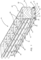
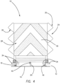
- Figs. 1-4 illustrate an exemplary embodiment of a fixed crash impact attenuator system 10 of the type discussed above, wherein the design is sacrificial, in that it is intended for a single impact only, after which it is replaced. Thus, it is designed to be relatively inexpensive and simple in design and construction, yet highly effective in protecting the occupants of vehicles striking the attenuator.
- one inch corresponds to 2,54 cm and one foot corresponds to 30,48 cm.
- Design considerations for the system 10 are that it meets U.S. federal TL (Test Level) -3 crash attenuation specifications, that it is narrow in profile, bidirectional capable, MASH (Manual for Assessing Safety Hardware) compliant, inexpensive, and free-standing (does not need to butt to rigid object, although it can, of course).
- the system is of a simple design and easy to manufacture (materials are standard sizes and shapes and fender panels are standard Thrie Beam-based), easy to assemble, and ships as a complete assembly.
- the base is the drill template, and anchor holes can be drilled with the unit 10 assembled.
- the length of the unit is designed, in an exemplary embodiment, is approximately 20-24 feet.
- the unit 10 may be anchored to concrete, asphalt, or a hybrid of both, and it is anchored using standard anchors and adhesives. It is suitable for use in temperatures ranging from -40 degrees to 150+ degrees F.
- the system 10 comprises a base portion 12 having a ladder frame design, comprising a plurality of cross members 14 supporting first and second outer rails 16 and 18, respectively, as well as a center rail 20.
- the cross members 14 include anchor holes 22 for anchoring the base to the ground using bolt anchors or other suitable mechanical fasteners. In some instances, adhesive may be used instead or as well.
- the anchor holes 22, in the illustrated embodiment, are spaced along a length of each cross member 14, both outside of and within the first and second outer rails 16, 18.
- the system 10 further includes an upper attenuator portion 24, which comprises a nose box 26, a plurality of diaphragms 28, and a plurality of fender panels 30.
- the nose box 26 may comprise a notice sign 32, and may include a crushable element in the front, behind the sign 32.
- the nose box 26 supports loads related to frontal, side, and angled nose impacts, and is supported on rollers 34, which allow the nose panel to move rearwardly along the outer rails 16, 18.
- the rollers 34 are designed to prevent binding/locking in an angled nose impact. As the nose box 26 moves rearwardly after a vehicular impact, attenuation may be activated.
- the diaphragms 28 are disposed in spaced relation behind the nose box 26. They are made from standard shapes and sizes and have cross braces sized for loads. Each cross brace is positioned for ease of assembly of the fender panels 30. Each diaphragm 28 is slidably mounted at their base ends 36 on each side to the outer rails 16, 18, as illustrated.
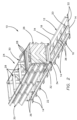
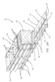
- the fender panels 30 are standard in construction, being a standard Thrie beam panel, preferably fabricated of 10 or 12-gauge steel. When a vehicular impact occurs, and the attenuator is compacted, as shown successively in Figs. 2 , 2a and 3 , 3a , the fender panels 30 are preferably designed to nest or double over one another in a sliding pattern, as illustrated in the drawings.
- the length of the fender panels 30 is determined by loads in side impacts, and panels are preferably designed to be common and interchangeable where possible.
- Bolts secure the foremost fender panel 30 to the nose box 26, and also secure the fender panels to the diaphragms 28.
- the rear of the panels 30 are secured by clips, rather than slots, in illustrated embodiments, though other attachment methods may be used.
- the system 10 is designed for standard Thrie beam transition pieces.
- the steel forming the fender panels may be galvanized, and may be A36, A513, or A517, for example.
- ripper plates may be used, with varied and staged thicknesses and shapes to stage attenuation, laser/plasma cut patterns to stage attenuation, or a cutter located on the nose box 26, for example.
- Shearing bolts may be used, comprising double shear approaches or a cutter on the nose box 26, for example.
- Failing wire rope sections comprising wire rope loops being pulled to failure, kinking of tube arches, cartridges with honeycomb (aluminum, steel, or plastic), crushable foam-filled cartridges, sand-filled cartridges, pea gravel filled cartridges, water-filled cartridges, cartridges filled with glass beads in oil, drawing a metal strip through offset rollers, a friction brake on a wire rope, a friction brake on bar stock, or velocity magnetics (magnetic attenuation) are all potential possibilities.
- FIGs. 1-4 An attenuation approach which is illustrated in Figs. 1-4 involves the center rail 20. As illustrated, the rail 20 is fixedly mounted to the cross members 14 of the base portion 12, in an upright orientation. As shown in Figs. 2a and 3a , a plurality of holes or apertures 38 are disposed in spaced relation along a length of the rail 20.
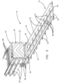
- Attenuation occurs as the upper attenuator portion 24 moves rearwardly upon impact by a vehicle, thus absorbing impact energy from the crash, and this attenuation capability is greatly enhanced by the employment of one or more inventive shear bolt or tearing member 40 (Figs. 2b, 3b, and 4 ), which extends from the attenuator portion 24, and engages the holes 38.
- inventive shear bolt or tearing member 40 FIG. 2b, 3b, and 4
- the tearing member 40 is disposed on the frontmost diaphragm 28, as shown, but it is within the scope of the invention to employ a plurality of tearing members 40, spaced widthwise on one diaphragm 28 to tear corresponding structural members like rail 20, or opposing sides of the rail 20, or, alternatively, to employ one or more tearing members 40 on more than one of the plurality of diaphragms 28.
- a plurality of tearing members 40 spaced widthwise on one diaphragm 28 to tear corresponding structural members like rail 20, or opposing sides of the rail 20, or, alternatively, to employ one or more tearing members 40 on more than one of the plurality of diaphragms 28.
- the holes 38 are ripped by the tearing member 40, thus absorbing much of the crash impact forces by ripping the material forming the rail 20, between the holes 38, creating a slot 42 in the rail 20.
- the holes 38 may be tuned to optimize the tearing, and thus attenuation effect, by changing their spacing in different sections of the rail 20, and/or by changing the size of the holes.
- the holes 38 may be more closely spaced in front portions of the rail 20, and may also be more elongated, to make the rail "softer" when crushed, whereas the holes 38 in more rearward portions of the rail 20 may be smaller and less elongated, and farther spaced apart, in order to make these portions of the attenuator "harder” when crushed, to attenuate higher forces.
- the rail 20 may be made of thinner material (gauge) in the forward sections, and thicker material (gauge) in the rearward sections, for similar reasons.
- the material of the rail itself might be changed as the attenuator travels along the rail from front to rear, from one stage to the next.
- the softer portions be forward and the harder portions be rearward
- differing design considerations may dictate a different orientation, such as softer portions being rearward and harder portions being forward.
- the diaphragms 28 serve to transfer the load of a side impact from the diaphragm to the pavement, through the cross members 14 and anchors 22. This anchoring to the pavement makes the pavement itself a structural member for the attenuator system 10.
Landscapes
- Engineering & Computer Science (AREA)
- Architecture (AREA)
- Civil Engineering (AREA)
- Structural Engineering (AREA)
- Vibration Dampers (AREA)
- Refuge Islands, Traffic Blockers, Or Guard Fence (AREA)
Claims (15)
- Aufpralldämpfersystem (10) zum Einsatz vor einer festen Struktur, wobei das System Folgendes umfasst:eine erste und zweite äußere Schiene (16, 18), die in einer Breitenrichtung beabstandet sind und sich entlang einer Länge des Aufpralldämpfersystems erstrecken;eine Mittelschiene (20); undeine Vielzahl von Membranen (28), die anfänglich in einer beabstandeten Beziehung entlang der Länge der ersten und zweiten äußeren Schiene angeordnet sind, wobei jede der Vielzahl von Membranen ein Basisende (36) aufweist, das angepasst ist, um bewegbar mit der ersten und zweiten äußeren Schiene in Eingriff zu treten, sodass, wenn ein vorderes Ende des Aufpralldämpfersystems eine Aufprallkraft von einem fehlgeleiteten Fahrzeug empfängt, sich eine erste aus der Vielzahl von Membranen entlang der ersten und zweiten äußeren Schiene nach hinten bewegt und auf eine zweite aus der Vielzahl von Membranen trifft, sodass sich sowohl die erste als auch die zweite aus der Vielzahl von Membranen entlang der ersten und zweiten äußeren Schiene weiter nach hinten bewegen, wobei dieser Prozess mit zusätzlichen aus der Vielzahl von Membranen fortgesetzt wird, bis die Aufprallkräfte vollständig gedämpft wurden; und dadurch gekennzeichnet, dass das System Folgendes umfasst:einen Bolzen (40) an einer der Vielzahl von Membranen, der angepasst ist, um in Material einzugreifen, das die Mittelschiene (20) des Aufpralldämpfersystems bildet, wobei der Bolzen und die Mittelschiene relativ bewegbar sind, wenn eine Aufprallkraft auf das Aufpralldämpfersystem auftrifft, sodass der Bolzen die Mittelschiene zerreißt, wodurch die Dämpfung der Aufprallkraft erhöht wird, wobei die Mittelschiene abgestimmt ist, um das Zerreißen der Mittelschiene zu optimieren;wobei sich die Mittelschiene entlang mindestens eines Abschnitts der Länge des Aufpralldämpfers erstreckt und eine Vielzahl von darin angeordneten Löchern (38) beinhaltet, wobei sich die Vielzahl von Löchern entlang einer Länge der Mittelschiene erstreckt und in Längsrichtung voneinander beabstandet ist, wobei der Bolzen mit einem aus der Vielzahl von Löchern in Eingriff steht, sodass, wenn eine Aufprallkraft auf den Aufpralldämpfer aufgebracht wird, eine relative Bewegung zwischen der Mittelschiene und dem Bolzen auftritt, sodass die relative Bewegung bewirkt, dass der Bolzen das Material zwischen benachbarten aus der Vielzahl von Löchern zerreißt, wodurch ein kontinuierlicher Schlitz (42) erzeugt wird, wobei das Zerreißen des Materials dazu dient, die Aufprallkraft zu dämpfen.
- Aufpralldämpfersystem nach Anspruch 1, wobei der Bolzen an einem Basisende der ersten der Vielzahl von Membranen angeordnet ist.
- Aufpralldämpfer nach Anspruch 1, wobei der Bolzen eine Vielzahl von Bolzen umfasst.
- Aufpralldämpfer nach Anspruch 1, wobei die Mittelschiene durch Anordnen der Vielzahl von Löchern abgestimmt ist, sodass die Vielzahl von Löchern nicht gleichmäßig entlang der Länge der Mittelschiene beabstandet ist.
- Aufpralldämpfer nach Anspruch 1, wobei benachbarte der Vielzahl von Löchern, die sich näher an einem von dem vorderen und hinteren Ende des Aufpralldämpfers befinden, enger beabstandet sind als benachbarte der Vielzahl von Löchern, die sich näher an dem anderen von dem vorderen und hinteren Ende des Aufpralldämpfers befinden.
- Aufpralldämpfer nach Anspruch 1, wobei die Mittelschiene durch Anordnen der Löcher abgestimmt ist, sodass die Vielzahl von Löchern jeweils bezogen aufeinander keine gleichmäßige Größe aufweist.
- Aufpralldämpfer nach Anspruch 5, wobei einzelne der Vielzahl von Löchern, die sich näher an dem einen von dem vorderen und hinteren Ende des Aufpralldämpfers befinden, größer und ausgedehnter sind als diejenigen der Vielzahl von Löchern, die sich näher an dem anderen von dem vorderen und hinteren Ende des Aufpralldämpfers befinden.
- Aufpralldämpfer nach Anspruch 1, wobei die Mittelschiene abgestimmt ist, sodass das Material, das die Mittelschiene bildet, in Richtung eines von dem vorderen und hinteren Ende des Aufpralldämpfers dünner und in Richtung des anderen von dem vorderen und hinteren Ende des Aufpralldämpfers dicker ist.
- Aufpralldämpfer nach Anspruch 1, wobei die Mittelschiene abgestimmt ist, indem sie die Mittelschiene einer Vielzahl von Stufen umfasst, wenn sie sich von einem von dem vorderen und hinteren Ende des Aufpralldämpfers in Richtung des anderen von dem ersten und zweiten Ende des Aufpralldämpfers erstreckt, wobei eine erste Stufe in Richtung des einen von dem vorderen und hinteren Ende des Aufpralldämpfers weicher ist als eine zweite Stufe in Richtung des anderen von dem ersten und zweiten Ende des Aufpralldämpfers.
- Aufpralldämpfer nach Anspruch 9, wobei das eine von dem vorderen und hinteren Ende des Aufpralldämpfers das vordere Ende des Aufpralldämpfers ist und das andere von dem ersten und zweiten Ende des Aufpralldämpfers das hintere Ende des Aufpralldämpfers ist.
- Aufpralldämpfer nach Anspruch 9, wobei die erste Stufe weicher ist, da das die erste Stufe bildende Material dünner als das die zweite Stufe bildende Material ist.
- Aufpralldämpfer nach Anspruch 9, wobei die erste Stufe weicher ist, da die Löcher der Vielzahl von Löchern, die in der ersten Stufe angeordnet sind, näher beieinander liegen als die Löcher der Vielzahl von Löchern, die in der zweiten Stufe angeordnet sind.
- Aufpralldämpfer nach Anspruch 9, wobei die erste Stufe weicher ist, da die Löcher der Vielzahl von Löchern, die in der ersten Stufe angeordnet sind, größer sind als die Löcher der Vielzahl von Löchern, die in der zweiten Stufe angeordnet sind.
- Aufpralldämpfer nach Anspruch 1, und ferner umfassend eine Vielzahl von Kotflügelplatten (30), die entlang jeder Seite des Aufpralldämpfers entlang seiner Länge angeordnet sind, wobei die vordersten der Vielzahl von Kotflügelplatten angepasst sind, um entlang der hintersten der Vielzahl von Kotflügelplatten zu gleiten, wenn ein Fahrzeug auf den Aufpralldämpfer auftrifft.
- Aufpralldämpfer nach Anspruch 1, wobei die Mittelschiene stationär ist und sich das Aufreißelement als Reaktion auf die Aufprallkraft bewegt.
Applications Claiming Priority (3)
| Application Number | Priority Date | Filing Date | Title |
|---|---|---|---|
| US201962915592P | 2019-10-15 | 2019-10-15 | |
| US202063054911P | 2020-07-22 | 2020-07-22 | |
| PCT/US2020/055797 WO2021076767A1 (en) | 2019-10-15 | 2020-10-15 | Crash impact attenuator systems and methods |
Publications (4)
| Publication Number | Publication Date |
|---|---|
| EP4045718A1 EP4045718A1 (de) | 2022-08-24 |
| EP4045718A4 EP4045718A4 (de) | 2023-11-01 |
| EP4045718B1 true EP4045718B1 (de) | 2025-04-30 |
| EP4045718C0 EP4045718C0 (de) | 2025-04-30 |
Family
ID=75382700
Family Applications (1)
| Application Number | Title | Priority Date | Filing Date |
|---|---|---|---|
| EP20876431.6A Active EP4045718B1 (de) | 2019-10-15 | 2020-10-15 | Aufpralldämpfer |
Country Status (8)
| Country | Link |
|---|---|
| US (2) | US20210108383A1 (de) |
| EP (1) | EP4045718B1 (de) |
| JP (1) | JP2022543707A (de) |
| KR (2) | KR20230074297A (de) |
| CN (1) | CN114364843A (de) |
| AU (1) | AU2020368434B2 (de) |
| CA (1) | CA3153150C (de) |
| WO (1) | WO2021076767A1 (de) |
Families Citing this family (7)
| Publication number | Priority date | Publication date | Assignee | Title |
|---|---|---|---|---|
| US11453988B2 (en) * | 2020-02-18 | 2022-09-27 | Lindsay Transportation Solutions, Llc | Crash cushion with improved side panel attachment |
| US11603635B2 (en) * | 2020-04-15 | 2023-03-14 | Lindsay Transportation Solutions, Llc | Crash cushion with improved reinforcing cable system |
| US11268250B2 (en) * | 2020-04-15 | 2022-03-08 | Lindsay Transportation Solutions, Llc | Crash cushion with improved side panel attachment |
| KR20260003846A (ko) * | 2020-06-19 | 2026-01-07 | 트래픽스 디바이시스 인코포레이티드 | 충돌 충격 감쇠기 시스템 및 방법 |
| BE1028548B1 (nl) * | 2020-08-17 | 2022-03-15 | Stuer Egghe Bvba | Botsabsorbeerinrichting, voertuig en aanhangwagen omvattende een botsabsorbeerinrichting |
| US12392097B2 (en) * | 2023-02-07 | 2025-08-19 | Lindsay Transportation Solutions, Llc | Restorable crash cushion apparatus |
| US20240263410A1 (en) * | 2023-02-07 | 2024-08-08 | Lindsay Transportation Solutions, Llc | Restorable crash cushion apparatus |
Family Cites Families (17)
| Publication number | Priority date | Publication date | Assignee | Title |
|---|---|---|---|---|
| US6293727B1 (en) * | 1997-06-05 | 2001-09-25 | Exodyne Technologies, Inc. | Energy absorbing system for fixed roadside hazards |
| US7306397B2 (en) * | 2002-07-22 | 2007-12-11 | Exodyne Technologies, Inc. | Energy attenuating safety system |
| US6461076B1 (en) * | 2001-01-03 | 2002-10-08 | Energy Absorption Systems, Inc. | Vehicle impact attenuator |
| WO2003095247A2 (en) * | 2002-05-13 | 2003-11-20 | Sung Ku Kang | Vehicular impact absorbing apparatus having cushion pins |
| US20040262588A1 (en) * | 2003-06-27 | 2004-12-30 | Trn Business Trust | Variable width crash cushions and end terminals |
| US7287930B2 (en) * | 2003-10-08 | 2007-10-30 | Nkc Co., Ltd. | Vehicle impact attenuator |
| CN102108687B (zh) * | 2003-12-09 | 2014-06-04 | 埃克索戴恩技术有限公司 | 能量削弱安全系统 |
| MX2007003064A (es) * | 2004-09-15 | 2007-05-21 | Energy Absorption System | Amortiguador de choque. |
| KR100707914B1 (ko) * | 2006-08-01 | 2007-04-13 | 주식회사 우전그린 | 도로 안전 방호대의 슬라이딩 스토퍼장치 |
| WO2008094943A1 (en) * | 2007-01-29 | 2008-08-07 | Traffix Devices, Inc. | Crash impact attenuator systems and methods |
| KR20100132428A (ko) * | 2009-06-09 | 2010-12-17 | (주) 임팩트 블랙홀 | 압연관 표면 드래그(drag)에 의한 운동 마찰력과 압연력을 이용한 차량충격을 흡수하는 방법 및 이를 이용한 차량충격흡수장치 |
| US9145943B2 (en) * | 2013-07-02 | 2015-09-29 | The Uab Research Foundation | Systems and methods for absorbing energy |
| EP3040480B1 (de) * | 2013-11-05 | 2020-04-22 | Shinsung Control Co., Ltd. | Kollisionsstossdämpfende vorrichtung |
| KR101977806B1 (ko) * | 2017-02-16 | 2019-05-13 | 주식회사 태백 | 차량 충돌 충격흡수장치 |
| KR101879200B1 (ko) * | 2017-07-13 | 2018-07-17 | 설지혜 | 도로용 충격흡수장치 |
| KR102100439B1 (ko) * | 2020-02-04 | 2020-04-13 | (주)미래로드셋 | 전방지지대의 후퇴 저항수단이 구비된 차량 충격흡수장치 |
| KR102298946B1 (ko) * | 2021-02-23 | 2021-09-09 | 주식회사 에프티알에스 | 개선된 구조의 전방지지대 후퇴 저항수단을 갖는 차량 충격흡수장치 |
-
2020
- 2020-10-15 EP EP20876431.6A patent/EP4045718B1/de active Active
- 2020-10-15 KR KR1020237016486A patent/KR20230074297A/ko not_active Ceased
- 2020-10-15 KR KR1020227008348A patent/KR20220035513A/ko not_active Ceased
- 2020-10-15 JP JP2022514774A patent/JP2022543707A/ja active Pending
- 2020-10-15 CN CN202080063713.6A patent/CN114364843A/zh active Pending
- 2020-10-15 WO PCT/US2020/055797 patent/WO2021076767A1/en not_active Ceased
- 2020-10-15 US US17/071,716 patent/US20210108383A1/en not_active Abandoned
- 2020-10-15 CA CA3153150A patent/CA3153150C/en active Active
- 2020-10-15 AU AU2020368434A patent/AU2020368434B2/en active Active
-
2022
- 2022-11-29 US US18/071,557 patent/US20230160162A1/en active Pending
Also Published As
| Publication number | Publication date |
|---|---|
| CA3153150C (en) | 2023-06-20 |
| CN114364843A (zh) | 2022-04-15 |
| EP4045718A1 (de) | 2022-08-24 |
| JP2022543707A (ja) | 2022-10-13 |
| US20230160162A1 (en) | 2023-05-25 |
| AU2020368434A1 (en) | 2022-04-14 |
| KR20220035513A (ko) | 2022-03-22 |
| AU2020368434B2 (en) | 2023-02-02 |
| WO2021076767A1 (en) | 2021-04-22 |
| US20210108383A1 (en) | 2021-04-15 |
| EP4045718A4 (de) | 2023-11-01 |
| EP4045718C0 (de) | 2025-04-30 |
| CA3153150A1 (en) | 2021-04-22 |
| KR20230074297A (ko) | 2023-05-26 |
Similar Documents
| Publication | Publication Date | Title |
|---|---|---|
| EP4045718B1 (de) | Aufpralldämpfer | |
| US4838523A (en) | Energy absorbing guard rail terminal | |
| KR101118920B1 (ko) | 차량 감속을 위한 케이블 및 실린더 장치를 가진 충돌 감쇠장치 | |
| CN100594274C (zh) | 碰撞缓冲器 | |
| US12345001B2 (en) | Crash impact attenuator systems and methods | |
| US7059590B2 (en) | Impact assembly for an energy absorbing device | |
| AU2003277189B2 (en) | Trailer mounted bursting energy absorbtion system | |
| AU2003275342A1 (en) | Single-sided crash cushion system | |
| CA1292905C (en) | Energy absorbing guard rail terminal | |
| WO2007035694A2 (en) | Yielding post guardrail safety system | |
| RU2007113904A (ru) | Аварийное заграждение |
Legal Events
| Date | Code | Title | Description |
|---|---|---|---|
| STAA | Information on the status of an ep patent application or granted ep patent |
Free format text: STATUS: THE INTERNATIONAL PUBLICATION HAS BEEN MADE |
|
| PUAI | Public reference made under article 153(3) epc to a published international application that has entered the european phase |
Free format text: ORIGINAL CODE: 0009012 |
|
| STAA | Information on the status of an ep patent application or granted ep patent |
Free format text: STATUS: REQUEST FOR EXAMINATION WAS MADE |
|
| 17P | Request for examination filed |
Effective date: 20220506 |
|
| AK | Designated contracting states |
Kind code of ref document: A1 Designated state(s): AL AT BE BG CH CY CZ DE DK EE ES FI FR GB GR HR HU IE IS IT LI LT LU LV MC MK MT NL NO PL PT RO RS SE SI SK SM TR |
|
| DAV | Request for validation of the european patent (deleted) | ||
| DAX | Request for extension of the european patent (deleted) | ||
| P01 | Opt-out of the competence of the unified patent court (upc) registered |
Effective date: 20230505 |
|
| A4 | Supplementary search report drawn up and despatched |
Effective date: 20231004 |
|
| RIC1 | Information provided on ipc code assigned before grant |
Ipc: E01F 15/04 20060101ALI20230927BHEP Ipc: E01F 15/14 20060101AFI20230927BHEP |
|
| R17P | Request for examination filed (corrected) |
Effective date: 20220506 |
|
| GRAP | Despatch of communication of intention to grant a patent |
Free format text: ORIGINAL CODE: EPIDOSNIGR1 |
|
| STAA | Information on the status of an ep patent application or granted ep patent |
Free format text: STATUS: GRANT OF PATENT IS INTENDED |
|
| INTG | Intention to grant announced |
Effective date: 20240723 |
|
| GRAJ | Information related to disapproval of communication of intention to grant by the applicant or resumption of examination proceedings by the epo deleted |
Free format text: ORIGINAL CODE: EPIDOSDIGR1 |
|
| STAA | Information on the status of an ep patent application or granted ep patent |
Free format text: STATUS: REQUEST FOR EXAMINATION WAS MADE |
|
| INTC | Intention to grant announced (deleted) | ||
| GRAP | Despatch of communication of intention to grant a patent |
Free format text: ORIGINAL CODE: EPIDOSNIGR1 |
|
| STAA | Information on the status of an ep patent application or granted ep patent |
Free format text: STATUS: GRANT OF PATENT IS INTENDED |
|
| INTG | Intention to grant announced |
Effective date: 20250103 |
|
| GRAS | Grant fee paid |
Free format text: ORIGINAL CODE: EPIDOSNIGR3 |
|
| GRAA | (expected) grant |
Free format text: ORIGINAL CODE: 0009210 |
|
| STAA | Information on the status of an ep patent application or granted ep patent |
Free format text: STATUS: THE PATENT HAS BEEN GRANTED |
|
| AK | Designated contracting states |
Kind code of ref document: B1 Designated state(s): AL AT BE BG CH CY CZ DE DK EE ES FI FR GB GR HR HU IE IS IT LI LT LU LV MC MK MT NL NO PL PT RO RS SE SI SK SM TR |
|
| REG | Reference to a national code |
Ref country code: CH Ref legal event code: EP Ref country code: GB Ref legal event code: FG4D |
|
| REG | Reference to a national code |
Ref country code: DE Ref legal event code: R096 Ref document number: 602020050600 Country of ref document: DE |
|
| REG | Reference to a national code |
Ref country code: IE Ref legal event code: FG4D |
|
| U01 | Request for unitary effect filed |
Effective date: 20250527 |
|
| P04 | Withdrawal of opt-out of the competence of the unified patent court (upc) registered |
Free format text: CASE NUMBER: APP_25913/2025 Effective date: 20250531 |
|
| U07 | Unitary effect registered |
Designated state(s): AT BE BG DE DK EE FI FR IT LT LU LV MT NL PT RO SE SI Effective date: 20250604 |
|
| PG25 | Lapsed in a contracting state [announced via postgrant information from national office to epo] |
Ref country code: ES Free format text: LAPSE BECAUSE OF FAILURE TO SUBMIT A TRANSLATION OF THE DESCRIPTION OR TO PAY THE FEE WITHIN THE PRESCRIBED TIME-LIMIT Effective date: 20250430 |
|
| PG25 | Lapsed in a contracting state [announced via postgrant information from national office to epo] |
Ref country code: NO Free format text: LAPSE BECAUSE OF FAILURE TO SUBMIT A TRANSLATION OF THE DESCRIPTION OR TO PAY THE FEE WITHIN THE PRESCRIBED TIME-LIMIT Effective date: 20250730 Ref country code: GR Free format text: LAPSE BECAUSE OF FAILURE TO SUBMIT A TRANSLATION OF THE DESCRIPTION OR TO PAY THE FEE WITHIN THE PRESCRIBED TIME-LIMIT Effective date: 20250731 |
|
| PG25 | Lapsed in a contracting state [announced via postgrant information from national office to epo] |
Ref country code: PL Free format text: LAPSE BECAUSE OF FAILURE TO SUBMIT A TRANSLATION OF THE DESCRIPTION OR TO PAY THE FEE WITHIN THE PRESCRIBED TIME-LIMIT Effective date: 20250430 |
|
| PG25 | Lapsed in a contracting state [announced via postgrant information from national office to epo] |
Ref country code: HR Free format text: LAPSE BECAUSE OF FAILURE TO SUBMIT A TRANSLATION OF THE DESCRIPTION OR TO PAY THE FEE WITHIN THE PRESCRIBED TIME-LIMIT Effective date: 20250430 |
|
| PG25 | Lapsed in a contracting state [announced via postgrant information from national office to epo] |
Ref country code: RS Free format text: LAPSE BECAUSE OF FAILURE TO SUBMIT A TRANSLATION OF THE DESCRIPTION OR TO PAY THE FEE WITHIN THE PRESCRIBED TIME-LIMIT Effective date: 20250731 |
|
| PG25 | Lapsed in a contracting state [announced via postgrant information from national office to epo] |
Ref country code: IS Free format text: LAPSE BECAUSE OF FAILURE TO SUBMIT A TRANSLATION OF THE DESCRIPTION OR TO PAY THE FEE WITHIN THE PRESCRIBED TIME-LIMIT Effective date: 20250830 |
|
| U20 | Renewal fee for the european patent with unitary effect paid |
Year of fee payment: 6 Effective date: 20251027 |
|
| PGFP | Annual fee paid to national office [announced via postgrant information from national office to epo] |
Ref country code: GB Payment date: 20251027 Year of fee payment: 6 |
|
| PG25 | Lapsed in a contracting state [announced via postgrant information from national office to epo] |
Ref country code: SM Free format text: LAPSE BECAUSE OF FAILURE TO SUBMIT A TRANSLATION OF THE DESCRIPTION OR TO PAY THE FEE WITHIN THE PRESCRIBED TIME-LIMIT Effective date: 20250430 |
|
| PG25 | Lapsed in a contracting state [announced via postgrant information from national office to epo] |
Ref country code: CZ Free format text: LAPSE BECAUSE OF FAILURE TO SUBMIT A TRANSLATION OF THE DESCRIPTION OR TO PAY THE FEE WITHIN THE PRESCRIBED TIME-LIMIT Effective date: 20250430 |
|
| PG25 | Lapsed in a contracting state [announced via postgrant information from national office to epo] |
Ref country code: SK Free format text: LAPSE BECAUSE OF FAILURE TO SUBMIT A TRANSLATION OF THE DESCRIPTION OR TO PAY THE FEE WITHIN THE PRESCRIBED TIME-LIMIT Effective date: 20250430 |
|
| PLBE | No opposition filed within time limit |
Free format text: ORIGINAL CODE: 0009261 |
|
| STAA | Information on the status of an ep patent application or granted ep patent |
Free format text: STATUS: NO OPPOSITION FILED WITHIN TIME LIMIT |
|
| REG | Reference to a national code |
Ref country code: CH Ref legal event code: L10 Free format text: ST27 STATUS EVENT CODE: U-0-0-L10-L00 (AS PROVIDED BY THE NATIONAL OFFICE) Effective date: 20260311 |