EP4045255B1 - Mold, mold system amd process for manufactuirng products from foamy particles - Google Patents
Mold, mold system amd process for manufactuirng products from foamy particles Download PDFInfo
- Publication number
- EP4045255B1 EP4045255B1 EP20786292.1A EP20786292A EP4045255B1 EP 4045255 B1 EP4045255 B1 EP 4045255B1 EP 20786292 A EP20786292 A EP 20786292A EP 4045255 B1 EP4045255 B1 EP 4045255B1
- Authority
- EP
- European Patent Office
- Prior art keywords
- mold
- cavities
- trimming
- fluid
- cavity
- Prior art date
- Legal status (The legal status is an assumption and is not a legal conclusion. Google has not performed a legal analysis and makes no representation as to the accuracy of the status listed.)
- Active
Links
- 239000002245 particle Substances 0.000 title claims description 121
- 238000000034 method Methods 0.000 title claims description 36
- 230000008569 process Effects 0.000 title claims description 23
- 238000009966 trimming Methods 0.000 claims description 165
- 239000012530 fluid Substances 0.000 claims description 162
- 239000006260 foam Substances 0.000 claims description 119
- 239000003990 capacitor Substances 0.000 claims description 84
- 239000000463 material Substances 0.000 claims description 59
- 230000005672 electromagnetic field Effects 0.000 claims description 38
- 238000003466 welding Methods 0.000 claims description 24
- 238000005187 foaming Methods 0.000 claims description 14
- 239000007787 solid Substances 0.000 claims description 5
- 239000007788 liquid Substances 0.000 claims description 4
- 238000003825 pressing Methods 0.000 claims description 3
- 238000005496 tempering Methods 0.000 claims description 3
- 238000007599 discharging Methods 0.000 claims description 2
- 238000003780 insertion Methods 0.000 claims description 2
- 230000037431 insertion Effects 0.000 claims description 2
- 230000005684 electric field Effects 0.000 description 27
- 238000004088 simulation Methods 0.000 description 17
- 238000004519 manufacturing process Methods 0.000 description 16
- 238000012986 modification Methods 0.000 description 13
- 230000004048 modification Effects 0.000 description 13
- 230000000694 effects Effects 0.000 description 10
- 230000003313 weakening effect Effects 0.000 description 10
- 239000003989 dielectric material Substances 0.000 description 8
- 238000010438 heat treatment Methods 0.000 description 8
- 239000004033 plastic Substances 0.000 description 7
- 239000000654 additive Substances 0.000 description 6
- 230000000996 additive effect Effects 0.000 description 6
- 238000005553 drilling Methods 0.000 description 6
- 230000007935 neutral effect Effects 0.000 description 5
- 238000012360 testing method Methods 0.000 description 5
- XLYOFNOQVPJJNP-UHFFFAOYSA-N water Substances O XLYOFNOQVPJJNP-UHFFFAOYSA-N 0.000 description 5
- 230000008901 benefit Effects 0.000 description 4
- 230000006835 compression Effects 0.000 description 4
- 238000007906 compression Methods 0.000 description 4
- 238000011161 development Methods 0.000 description 4
- 238000009826 distribution Methods 0.000 description 4
- 230000001788 irregular Effects 0.000 description 4
- 229910052751 metal Inorganic materials 0.000 description 4
- 239000002184 metal Substances 0.000 description 4
- 230000002093 peripheral effect Effects 0.000 description 4
- 238000013022 venting Methods 0.000 description 4
- 230000003321 amplification Effects 0.000 description 3
- 230000008859 change Effects 0.000 description 3
- 230000001276 controlling effect Effects 0.000 description 3
- 238000001816 cooling Methods 0.000 description 3
- 230000001419 dependent effect Effects 0.000 description 3
- 238000003199 nucleic acid amplification method Methods 0.000 description 3
- 238000010146 3D printing Methods 0.000 description 2
- 238000012935 Averaging Methods 0.000 description 2
- 239000004696 Poly ether ether ketone Substances 0.000 description 2
- 239000004743 Polypropylene Substances 0.000 description 2
- 239000004809 Teflon Substances 0.000 description 2
- 229920006362 Teflon® Polymers 0.000 description 2
- 230000002745 absorbent Effects 0.000 description 2
- 239000002250 absorbent Substances 0.000 description 2
- 239000007864 aqueous solution Substances 0.000 description 2
- JUPQTSLXMOCDHR-UHFFFAOYSA-N benzene-1,4-diol;bis(4-fluorophenyl)methanone Chemical compound OC1=CC=C(O)C=C1.C1=CC(F)=CC=C1C(=O)C1=CC=C(F)C=C1 JUPQTSLXMOCDHR-UHFFFAOYSA-N 0.000 description 2
- 230000000903 blocking effect Effects 0.000 description 2
- 238000005266 casting Methods 0.000 description 2
- 239000000919 ceramic Substances 0.000 description 2
- 238000005336 cracking Methods 0.000 description 2
- 238000013461 design Methods 0.000 description 2
- 210000003027 ear inner Anatomy 0.000 description 2
- 238000005516 engineering process Methods 0.000 description 2
- 230000004927 fusion Effects 0.000 description 2
- 239000011521 glass Substances 0.000 description 2
- 239000011159 matrix material Substances 0.000 description 2
- 239000012188 paraffin wax Substances 0.000 description 2
- 230000010287 polarization Effects 0.000 description 2
- 229920002530 polyetherether ketone Polymers 0.000 description 2
- 229920001155 polypropylene Polymers 0.000 description 2
- 238000007493 shaping process Methods 0.000 description 2
- 238000012546 transfer Methods 0.000 description 2
- 238000009423 ventilation Methods 0.000 description 2
- 241000264877 Hippospongia communis Species 0.000 description 1
- 238000010521 absorption reaction Methods 0.000 description 1
- 230000009471 action Effects 0.000 description 1
- 230000004913 activation Effects 0.000 description 1
- 230000006978 adaptation Effects 0.000 description 1
- 239000000853 adhesive Substances 0.000 description 1
- 238000004026 adhesive bonding Methods 0.000 description 1
- 230000001070 adhesive effect Effects 0.000 description 1
- 238000013459 approach Methods 0.000 description 1
- JRPBQTZRNDNNOP-UHFFFAOYSA-N barium titanate Chemical compound [Ba+2].[Ba+2].[O-][Ti]([O-])([O-])[O-] JRPBQTZRNDNNOP-UHFFFAOYSA-N 0.000 description 1
- 229910002113 barium titanate Inorganic materials 0.000 description 1
- 230000004888 barrier function Effects 0.000 description 1
- 230000015572 biosynthetic process Effects 0.000 description 1
- 230000000052 comparative effect Effects 0.000 description 1
- 239000004020 conductor Substances 0.000 description 1
- 238000000280 densification Methods 0.000 description 1
- 229920006248 expandable polystyrene Polymers 0.000 description 1
- 239000006261 foam material Substances 0.000 description 1
- 230000005484 gravity Effects 0.000 description 1
- 210000003128 head Anatomy 0.000 description 1
- 238000003754 machining Methods 0.000 description 1
- 238000002844 melting Methods 0.000 description 1
- 230000008018 melting Effects 0.000 description 1
- 238000010327 methods by industry Methods 0.000 description 1
- 238000003801 milling Methods 0.000 description 1
- 239000000203 mixture Substances 0.000 description 1
- 238000005457 optimization Methods 0.000 description 1
- BPUBBGLMJRNUCC-UHFFFAOYSA-N oxygen(2-);tantalum(5+) Chemical compound [O-2].[O-2].[O-2].[O-2].[O-2].[Ta+5].[Ta+5] BPUBBGLMJRNUCC-UHFFFAOYSA-N 0.000 description 1
- 229920000642 polymer Polymers 0.000 description 1
- 229920000098 polyolefin Polymers 0.000 description 1
- -1 polypropylene Polymers 0.000 description 1
- 229910052573 porcelain Inorganic materials 0.000 description 1
- 238000012805 post-processing Methods 0.000 description 1
- 238000011112 process operation Methods 0.000 description 1
- 230000009467 reduction Effects 0.000 description 1
- 230000001105 regulatory effect Effects 0.000 description 1
- 238000007789 sealing Methods 0.000 description 1
- 238000005245 sintering Methods 0.000 description 1
- 238000003860 storage Methods 0.000 description 1
- 239000000126 substance Substances 0.000 description 1
- PBCFLUZVCVVTBY-UHFFFAOYSA-N tantalum pentoxide Inorganic materials O=[Ta](=O)O[Ta](=O)=O PBCFLUZVCVVTBY-UHFFFAOYSA-N 0.000 description 1
- 229920001169 thermoplastic Polymers 0.000 description 1
- 239000004416 thermosoftening plastic Substances 0.000 description 1
- 230000007704 transition Effects 0.000 description 1
- 238000007514 turning Methods 0.000 description 1
- 239000002023 wood Substances 0.000 description 1
Images


Classifications
-
- B—PERFORMING OPERATIONS; TRANSPORTING
- B29—WORKING OF PLASTICS; WORKING OF SUBSTANCES IN A PLASTIC STATE IN GENERAL
- B29C—SHAPING OR JOINING OF PLASTICS; SHAPING OF MATERIAL IN A PLASTIC STATE, NOT OTHERWISE PROVIDED FOR; AFTER-TREATMENT OF THE SHAPED PRODUCTS, e.g. REPAIRING
- B29C35/00—Heating, cooling or curing, e.g. crosslinking or vulcanising; Apparatus therefor
- B29C35/02—Heating or curing, e.g. crosslinking or vulcanizing during moulding, e.g. in a mould
- B29C35/08—Heating or curing, e.g. crosslinking or vulcanizing during moulding, e.g. in a mould by wave energy or particle radiation
- B29C35/0805—Heating or curing, e.g. crosslinking or vulcanizing during moulding, e.g. in a mould by wave energy or particle radiation using electromagnetic radiation
-
- B—PERFORMING OPERATIONS; TRANSPORTING
- B29—WORKING OF PLASTICS; WORKING OF SUBSTANCES IN A PLASTIC STATE IN GENERAL
- B29C—SHAPING OR JOINING OF PLASTICS; SHAPING OF MATERIAL IN A PLASTIC STATE, NOT OTHERWISE PROVIDED FOR; AFTER-TREATMENT OF THE SHAPED PRODUCTS, e.g. REPAIRING
- B29C44/00—Shaping by internal pressure generated in the material, e.g. swelling or foaming ; Producing porous or cellular expanded plastics articles
- B29C44/34—Auxiliary operations
- B29C44/36—Feeding the material to be shaped
- B29C44/38—Feeding the material to be shaped into a closed space, i.e. to make articles of definite length
- B29C44/44—Feeding the material to be shaped into a closed space, i.e. to make articles of definite length in solid form
- B29C44/445—Feeding the material to be shaped into a closed space, i.e. to make articles of definite length in solid form in the form of expandable granules, particles or beads
-
- B—PERFORMING OPERATIONS; TRANSPORTING
- B29—WORKING OF PLASTICS; WORKING OF SUBSTANCES IN A PLASTIC STATE IN GENERAL
- B29C—SHAPING OR JOINING OF PLASTICS; SHAPING OF MATERIAL IN A PLASTIC STATE, NOT OTHERWISE PROVIDED FOR; AFTER-TREATMENT OF THE SHAPED PRODUCTS, e.g. REPAIRING
- B29C67/00—Shaping techniques not covered by groups B29C39/00 - B29C65/00, B29C70/00 or B29C73/00
- B29C67/20—Shaping techniques not covered by groups B29C39/00 - B29C65/00, B29C70/00 or B29C73/00 for porous or cellular articles, e.g. of foam plastics, coarse-pored
- B29C67/205—Shaping techniques not covered by groups B29C39/00 - B29C65/00, B29C70/00 or B29C73/00 for porous or cellular articles, e.g. of foam plastics, coarse-pored comprising surface fusion, and bonding of particles to form voids, e.g. sintering
-
- B—PERFORMING OPERATIONS; TRANSPORTING
- B29—WORKING OF PLASTICS; WORKING OF SUBSTANCES IN A PLASTIC STATE IN GENERAL
- B29C—SHAPING OR JOINING OF PLASTICS; SHAPING OF MATERIAL IN A PLASTIC STATE, NOT OTHERWISE PROVIDED FOR; AFTER-TREATMENT OF THE SHAPED PRODUCTS, e.g. REPAIRING
- B29C35/00—Heating, cooling or curing, e.g. crosslinking or vulcanising; Apparatus therefor
- B29C35/02—Heating or curing, e.g. crosslinking or vulcanizing during moulding, e.g. in a mould
- B29C35/08—Heating or curing, e.g. crosslinking or vulcanizing during moulding, e.g. in a mould by wave energy or particle radiation
- B29C35/0805—Heating or curing, e.g. crosslinking or vulcanizing during moulding, e.g. in a mould by wave energy or particle radiation using electromagnetic radiation
- B29C2035/0855—Heating or curing, e.g. crosslinking or vulcanizing during moulding, e.g. in a mould by wave energy or particle radiation using electromagnetic radiation using microwave
-
- B—PERFORMING OPERATIONS; TRANSPORTING
- B29—WORKING OF PLASTICS; WORKING OF SUBSTANCES IN A PLASTIC STATE IN GENERAL
- B29C—SHAPING OR JOINING OF PLASTICS; SHAPING OF MATERIAL IN A PLASTIC STATE, NOT OTHERWISE PROVIDED FOR; AFTER-TREATMENT OF THE SHAPED PRODUCTS, e.g. REPAIRING
- B29C35/00—Heating, cooling or curing, e.g. crosslinking or vulcanising; Apparatus therefor
- B29C35/02—Heating or curing, e.g. crosslinking or vulcanizing during moulding, e.g. in a mould
- B29C35/08—Heating or curing, e.g. crosslinking or vulcanizing during moulding, e.g. in a mould by wave energy or particle radiation
- B29C35/0805—Heating or curing, e.g. crosslinking or vulcanizing during moulding, e.g. in a mould by wave energy or particle radiation using electromagnetic radiation
- B29C2035/0861—Heating or curing, e.g. crosslinking or vulcanizing during moulding, e.g. in a mould by wave energy or particle radiation using electromagnetic radiation using radio frequency
-
- C—CHEMISTRY; METALLURGY
- C08—ORGANIC MACROMOLECULAR COMPOUNDS; THEIR PREPARATION OR CHEMICAL WORKING-UP; COMPOSITIONS BASED THEREON
- C08J—WORKING-UP; GENERAL PROCESSES OF COMPOUNDING; AFTER-TREATMENT NOT COVERED BY SUBCLASSES C08B, C08C, C08F, C08G or C08H
- C08J9/00—Working-up of macromolecular substances to porous or cellular articles or materials; After-treatment thereof
- C08J9/22—After-treatment of expandable particles; Forming foamed products
- C08J9/228—Forming foamed products
- C08J9/232—Forming foamed products by sintering expandable particles
Definitions
- the present invention relates to a tool, a tool system and a method for producing particle foam parts.
- the tool and the tool system for producing particle foam parts are provided for producing the particle foam parts using electromagnetic waves, with foam particles being welded to form a particle foam part by means of the electromagnetic waves.
- the energy required for welding is applied to the foam particles by means of electromagnetic waves.
- GB1,403,326 describes a method for welding expandable polystyrene foam particles, in which the particles are moistened with an aqueous solution and exposed to an electromagnetic field of 5 to 2000 MHz.
- WO 01/064414 A1 shows a method in which polymer particles made of polyolefins, which are wetted with a liquid medium, with electromagnetic waves, in particular Microwaves, to be heated.
- the temperature in the mold is regulated by controlling the pressure therein.
- WO 2013/050181 A1 describes a method for producing particle foam parts, in which a mixture of foam particles and dielectric transfer liquid is heated by means of electromagnetic waves in order to fuse the foam particles into a particle foam part. Radio waves or microwaves are used as electromagnetic waves.
- the material of the foam particles is made of polypropylene (PP).
- PP polypropylene
- the applicant of the present patent application has further developed the devices for welding foam particles using electromagnetic waves and the corresponding processes in such a way that it is able to produce larger numbers of foam particles using near-series prototypes by welding the foam particles using electromagnetic waves.
- These devices and methods are based on the WO 2017/127310 A1 , WO 2017/127312 A1 and WO 2018/100173 A2
- the technology described, which insofar as it is disclosed in connection with the invention described below in its entirety, and in particular relating to the devices and methods as well as materials, is additionally, but not exclusively, referred to.
- the electromagnetic waves are influenced by the material of the tool that delimits the mold cavity. There are different effects here. On the one hand, part of the energy of the electromagnetic waves can be absorbed by the material of the mold. On the other hand, this material acts as a dielectric, which is polarized in such a way that it creates an electromagnetic field opposite to the electromagnetic waves. As a result, the energy density of the electromagnetic waves is shifted and can be concentrated locally in the mold cavity. The inventors of the present invention took this into account for the first time when developing the present invention.
- the material from which the foam particles are formed can also have an influence on the electromagnetic field, so that when different materials are used, the same tool acts differently.
- Another problem is that it is practically impossible to post-optimize RF foaming tools, for example to increase the electric field in some areas.
- heating with an RF field is from the inside out, welding of outer layers of particles becomes poorer than at the core, and the surface can remain rough. In order to improve this, heating and cooling channels were previously provided in the tool.
- the foam particles are introduced into the mold cavity mixed with water as a heat transfer medium. During welding, the water can then be pressed out of the mold cavity. This can the average relative permittivity in the mold cavity changes and with it the local electric field strength. Controlling such a process is difficult.
- a device for producing particle foam parts In a device for producing particle foam parts, one wants to produce different particle foam parts. To do this, the corresponding tools, which define a mold cavity in which the particle foam parts are formed, have to be exchanged. This is already well known from conventional devices for producing particle foam parts, which weld the foam particles by means of steam.
- the inventors of the present invention have recognized that, unlike when welding foam particles by means of steam, when welding by means of electromagnetic waves, the function of a tool depends on the shape, which is predetermined by the shape of the particle foam part to be produced. This is also one of the main reasons why, despite the most intensive tests and development efforts for decades, it has never been possible to develop devices for welding particle foam parts, in particular those with an irregular shape or thickness or strong contours, using electromagnetic waves that are suitable for series production .
- the invention is therefore based on the object of creating a tool for producing particle foam parts and a corresponding tool system with which foam particles can be welded reliably and with high quality in a simple manner by means of electromagnetic waves.
- One object of the present invention is in particular to specify a tool, a tool system and a method which avoids or at least improves the disadvantages and problems mentioned above.
- a further object of the present invention is to create a possibility for subsequent optimization of such a tool.
- a further object of the present invention is to improve a tool, a tool system and a method with regard to a uniform quality of the welding in the cross section of the particle foam part.
- a further object of the present invention is to create a possibility of compensating for a change in the relative permittivity in the mold cavity during the foaming process and/or influencing the electromagnetic field prevailing in the mold cavity, in particular with regard to the electric field strength, during the foaming process.
- the tool according to the invention for producing particle foam parts by welding foam particles by means of electromagnetic waves comprises two mold halves which delimit a mold cavity. At least one of the two mold halves is made of a material that is transparent to electromagnetic waves and has a boundary wall delimiting the mold cavity and one or more supports which serve to support the boundary wall on a capacitor plate on the side facing away from the mold cavity and one or more cavities in the Form mold half.
- the mold halves are therefore preferably designed in such a way that they have an average permittivity which approximately corresponds to the permittivity of the foam particles to be welded. This gives a very homogeneous electric field even when the mold cavity is complex contoured.
- mold halves with similar dielectric properties as the object to be manufactured can be realized in a simple manner.
- the dielectric properties of the mold half can be matched to the particle foam part in a surprisingly simple manner. If the dielectric properties of the mold half roughly correspond to those of the particle foam part, this also has the advantage that the electromagnetic field is approximately homogeneous in the entire area between the capacitor plates, regardless of the shape of the mold half or particle foam part.
- the capacitor plate can be supported by the supports directly or indirectly (i.e. with an intermediate layer).
- the supports can be realized by side walls and/or intermediate walls.
- the boundary wall and the supports can be designed in one piece, in particular monolithically. In some forms forms a capacitor plate already a limitation of the mold cavity.
- each of the two mold halves to be made of the material that is transparent to electromagnetic waves and to have the boundary wall and the support(s).
- the boundary wall of the at least one mold half is preferably formed with a substantially constant thickness.
- the supports of the at least one mold half preferably run parallel to a pressing direction with which the mold halves are pressed together during operation with a press.
- the mold halves can have connections for a temperature control medium that can flow through the one or more cavities.
- the at least one of the two mold halves can be configured to trim the mold half by means of the one or more supports and/or the one or more cavities in order to influence an electromagnetic field in the mold cavity. It is thus possible to trim or adjust such a tool subsequently, ie after it has been manufactured. This allows the tool to be adjusted individually.
- the tool can thus be adapted on the one hand to the electrical field provided by a device for producing particle foam parts.
- the distribution of the electric field within the mold cavity can be individually adjusted, i.e. that in certain areas the electric field is increased compared to other areas when a trimming body is inserted into the cavity of the mold half adjacent to these areas. This allows the electrical field in the tool to be adapted to the geometry of the mold cavity.
- the electrical field can be adapted to the material from which the foam particles are formed, which are to be welded to form a particle foam part.
- Different materials from which the foam particles are formed act differently on an applied electrical field.
- the tool may work very well with a first material in a particular setting, but not with a second material. By exchanging or changing the arrangement of trimming bodies in the tool, this can be adapted to the second material.
- the tool according to the invention can be subsequently trimmed or adjusted, and can thus also be subsequently adapted to correspondingly changed circumstances (e.g. another device for producing a particle foam part or other material to be welded).
- a dielectric material for trimming it is possible, for example, to introduce a dielectric material into the mold half.
- This dielectric material is polarized when an electric field is applied, so that an electric field that counteracts the electric field is generated in the dielectric material.
- the electrical field is concentrated and increased in the area of the mold cavity, as a result of which the welding effect for welding foam particles to form a particle foam part is increased.
- At least the at least one mold half has at least one opening opening into the cavity, so that a trimming body can be inserted into the cavity.
- the wall delimiting the mold cavity is of course designed without an opening.
- the opening can preferably point to the side facing away from the mold cavity, but can also preferably point to the side.
- the cavity or at least one of the plurality of cavities can have a shaped or latching element for positioning and/or fixing a trimming body in the cavity.
- the mold half can have at least one connection for a trimming fluid, which is connected to at least one of the one or more cavities.
- a trimming fluid can thus be conducted through the at least one cavity or into the cavity or out of the cavity.
- the cavities are preferably connected to one another in a fluid-communicating manner, so that the cavities can be supplied jointly via a single connection or a few, in particular two, connections for trimming fluid.
- at least partial volumes of a plurality of cavities can be separated from one another in a fluid-tight manner, so that the cavities or partial volumes thereof can be charged individually with trimming fluid.
- a partial volume can be delimited, for example, by a cover arranged in the cavity. The cover can be mounted within the cavity so that it can be adjusted in height and can be prestressed in one direction and/or adjustable in height.
- connection for compressed air and/or vacuum can be provided, which is connected to at least one of the one or more cavities.
- the at least one cavity can be pressurized with compressed air or vacuum in order, for example, to force the trimming fluid out of the at least one cavity or to suck it into the at least one cavity.
- the at least one connection for compressed air and/or vacuum is preferably arranged at a higher level than the at least one connection for a trimming fluid, so that the trimming fluid can collect in the lower area of the cavities and the compressed air or vacuum connection remains free.
- the cavities are preferably connected by connection openings in the supports, the connection openings or a group of connection openings being aligned/aligned with at least one of connections for temperature control medium, trimming fluid, compressed air or vacuum.
- connection(s) for the temperature control medium, trimming fluid, compressed air or vacuum can be formed in a side wall which laterally closes off the mold half and acts as a support.
- the connection openings can be formed in webs which run between side walls and act as a support.
- Another aspect of the present invention relates to a tool system for producing particle foam parts, which comprises a tool as explained above and at least one trimming body, which is designed for introduction into the or at least one of the cavities, and/or a trimming fluid supply device, which is designed to supply the at least one mold half formed with a trimming fluid.
- the trim body is preferably made of a material with a relative permittivity ( ⁇ r) of at least 2.
- ⁇ r relative permittivity
- the trimming body can be designed as a plug-in body which can be fixed in the mold half, for example by means of a latching element or by means of a friction fit.
- the trimming body can thus be easily exchanged on the mold half, so that the mold half can be adapted to different production conditions.
- the trimming body can be designed in such a way that it only fills part of the cavity or cavities.
- the trimming body is arranged in the respective cavity in such a way that it is preferably located at a distance from the mold cavity. As a result, the cavity adjacent to the mold cavity is still free and can be used to conduct a temperature control medium.
- the trimming body can be formed from a solid body.
- the trimming body can be formed from a plastic body.
- the trim body can also be produced by filling one or more of the cavities with a curing material.
- the tool system can also have a plurality of trimming bodies which are of different sizes and/or are made of different materials and have a different relative permittivity.
- the tool system can also have a connection plate, which is to be arranged between a capacitor plate and a mold half of the tool or on a side of a capacitor plate facing away from a mold half of the tool, and the media connections and/or media channels and/or media openings for supplying and/or discharging media to the cavities of the mold half from or to the outside.
- the connection plate can have pieces of pipe which protrude into the cavities of the mold half when the connection plate is installed as intended.
- Media, in particular trimming fluid can be introduced into the cavities with the connection plate.
- the media can be introduced jointly into all cavities or individually into individual cavities or groups of cavities.
- a method for producing one or more particle foam parts by welding foam particles by means of electromagnetic waves wherein a tool with mold halves forming a mold cavity is arranged between two capacitor plates, the mold cavity is filled with foam particles, the tool by approaching of the two mold halves is closed and the tool with the foam particles in the mold cavity is exposed to electromagnetic waves, in particular radio or microwaves, introduced via the capacitor plates, the foam particles being heated by the electromagnetic waves and at least partially merging or baking with one another, the method is performed using the tool or tool system described above.
- One or more trimming bodies or a trimming fluid can be arranged in the or at least one of the cavities in order to influence an electromagnetic field in the mold cavity.
- the arrangement of one or more trimming bodies or the trimming fluid in the tool is changed during a foaming process in order to create an electromagnetic one to dynamically influence the field in the mold cavity.
- a trim body can be placed adjacent to that area, thereby increasing the electric field in the mold cavity in which that area is being produced. If, on the other hand, the particle foam part has melted too much at one point, trimming bodies can be used on the trimming wall mold half in the other areas that are not adjacent to this point, and the heating output can be reduced overall by either applying the electric field for a shorter period of time and/or the electrical field strength (or the electrical voltage in the case of an RF field applied by means of capacitor plates) is reduced.
- this method can be used to correct both areas with excessive heating and areas with insufficient heating.
- the trimming bodies can also be machined to change their shape to adjust the electric field.
- the present invention makes it possible to carry out a local adjustment of the electromagnetic field in a mold cavity of a tool for the production of a particle foam part, even for planar capacitor plates, which is considerably simpler in production and handling.
- the shaping tool half is designed such that the resulting relative permittivity of the tool agrees well with the relative permittivity of the particle foam.
- the tool half has free areas or volumes (one or more cavities) beyond the boundary wall and supports such as walls or webs, possibly also ribs, posts, honeycombs, zigzag labyrinths, etc.
- the relation of a volume of supporting material and air determines the desired relative permittivity and can be, for example, at least 0.05 or 0.1 and/or up to 0.3 or 0.5 or 0.7 or 0.9. If the electromagnetic field is to be strengthened locally in order to subsequently optimize the tool, trimming bodies can be introduced into the cavities.
- the supports are designed as a labyrinth, they can already be used as a cooling or heating channel for this reason and without further effort. As a result, Vario temperature control with air or CO2 or another temperature control medium is also possible.
- the tool according to the invention enables design without simulation and design rules are simply defined.
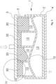
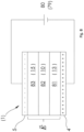
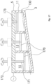
- a first exemplary embodiment of a tool 1 according to the invention for producing a particle foam part has two mold halves 2, 3 ( 1 ).
- a first (lower in the figure) mold half 2 is formed from a bottom wall 7 and a peripheral side wall 8 .
- a first capacitor plate 4 is arranged on the outside of the bottom wall 7 .
- the other, namely a second mold half 3 (upper in the figure) has a boundary wall 10 and a peripheral side wall 11 and is designed as a kind of punch which can be inserted with little play into the area bounded by the peripheral side wall 8, so that a mold cavity 13 is delimited between the two mold halves 2, 3, the side wall 11 of the second mold half 3 pointing away from the mold cavity 13.
- the second mold half 3 is thus referred to as the stamp mold half 3 and the first mold half 2 as the female mold half 2 .
- a plurality of webs 12 protrude from the boundary wall 10 on the same side as the side wall 11 .
- the webs 12 are connected to the side wall 11 and end at a level on which a second capacitor plate 5 rests.
- the webs 12 and the side wall 11 of the stamp mold half 3 are thus supports within the meaning of the invention, which are used to support the boundary wall 10 on the second capacitor plate 5.
- the second capacitor plate 5 has a waveguide connection 6 for connecting a waveguide.
- the side walls 11 and webs 12 of the stamp mold half 3 each form cavities 15 with one another and with the boundary wall 10, which cavities each have an opening 14 at the top.
- the second capacitor plate 5 is connected or connectable to a piston rod of a press in order to move the male mold half 3 with respect to the female mold half 2 and in particular to insert the male mold half 3 into the female mold half 2 (direction of an outlined arrow in FIG 1 ).
- a filling opening 9 for feeding foam particles into the mold cavity 13 is formed on the side wall 8 of the female mold half 2 ( 1 ). Furthermore, a ventilation opening (not shown) can also be provided on the side wall 8, from which the air can escape when the mold cavity 13 is filled.
- the tool 1 is provided in order to produce particle foam parts by welding foam particles introduced into the mold cavity 13 by means of electromagnetic waves.
- the first capacitor plate 4 can be connected to ground or earth and the second capacitor plate 5 can be connected to a wave generator via the waveguide connection 6 .
- a wave generator such as an RF or microwave generator is connected, a high-frequency electromagnetic field is generated in the mold cavity 13 .
- the foam particles are melted or melted and welded together by the energy of the electromagnetic field.
- the strength of the electromagnetic field prevailing in the mold cavity 13 depends on the properties of the substances present between the capacitor plates 4, 5, in particular on their relative permittivity ⁇ r.
- the relative permittivity ⁇ r is defined as the ratio of the permittivity of a material or medium to the permittivity of the vacuum, the electric field constant ⁇ 0.
- the relative permittivity ⁇ r depends on the material and can be understood as a measure for the field-weakening effects of a dielectric polarization of the material. The greater the relative permittivity ⁇ r of a material, the greater the field weakening.
- the mold halves 2, 3 are transparent (i.e. fundamentally transmissive) to electromagnetic waves, in particular those having a wavelength of the waves generated by the wave generator. That is, at least the bottom wall 7 of the female mold half 2 and the boundary wall 10 of the stamp mold half 3 are made of a dielectric material, which includes, for example, plastic, wood, ceramics, glass or the like.
- the foam particles introduced into the mold cavity 13 also have dielectric properties. Not only with an irregular geometry of the mold cavity 13, but also with locally different materials of the foam particles and influences from the mold halves 2, 3 themselves, locally different field strengths of the electromagnetic field can prevail in the mold cavity 13 or in the particle foam part to be formed and/or or the energy of the electromagnetic field is locally absorbed to different extents by the foam particles in the mold cavity 13 .
- Such irregular field strengths and/or degrees of absorption can be desirable, for example because the melting capacity of different foam materials can also differ, but they can also be undesirable. This can lead to insufficient or excessive heating and thus to undesirable fusion results of the foam particles.
- the cavities 15 of the male mold half 3 are provided, which reduce the mass of material in the male mold half 3 considerably. This in turn leads to an advantageous reduction in the influence on the electromagnetic field strength in the mold cavity 13, which considerably improves the flexibility in use and in the shaping of the mold cavity 13 and the stamp mold half 3.
- the cavities 15 can be used to trim the stamp mold half 3 in order to influence the electromagnetic field in the mold cavity 13 .
- the electromagnetic field in the mold cavity 13 can be influenced by suitable trimming in such a way that a uniform or otherwise desirable distribution of the field strength prevails in the mold cavity 13 .
- the foam particles are melted too much or even burned or charred at the points of higher compression and/or the welding of the foam particles is not sufficient at the adjacent points. Therefore, it may be desirable to have the field strength lower at the locations of higher densification of the foam particles than at the adjacent locations.
- material mixes with sections of more strongly absorbent foam particles and sections of less strongly absorbent foam particles.
- the tool 1 and the foam selection have been coordinated in advance using models or tests, but later in series production deviations in the fusion behavior occur, for example due to the use of a changed recipe or just a different batch of foam particles. In all of these cases it may be desirable to influence the electromagnetic field in the mold cavity 13.
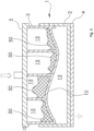
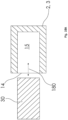
- trimming bodies 30 can be inserted into the cavities 15 through the openings 14 ( 3 ).
- the shims 30 are made of a dielectric material. Due to the polarizing properties of a dielectric, the alternating electromagnetic field is weakened by the dielectric lying in the path of the field lines. On the other hand, in areas on the path of the same field lines that are kept free by the dielectric, the field is not weakened or even strengthened. The electrical field can thus be influenced in different ways by trimming bodies 30 of different size, shape and permittivity.
- the side walls 3 and webs 12 of the stamp mold half 3 can have shoulders 41 in the area of the openings 14 and the trimming bodies 30 can have rims 42 or similar shape features on the upper side when inserting the trimming body 30, support it on the shoulders 41 ( Figure 4A ).
- the side walls 3 and webs 12 of the stamp mold half 3 can have locking elements 43 in the area of the openings 14 or continuously or in other areas, and the trimming bodies 30 can have corresponding shape features on the side, which snap into the locking elements 43 when the trimming bodies 30 are inserted ( Figure 4B ).
- trimming bodies 30 may be designed to hold in cavities 15 by sheer friction.
- trimming bodies 50 can also be formed by inserting a moldable dielectric material into the cavities 15 to be trained ( figure 5 ).
- the trimming bodies 50 can be attached particularly easily to the inside of the boundary wall 10 .
- the dielectric material of the trimming bodies 50 can be curable after insertion or can be highly tough and preferably adhesive to the material of the second mold half 3 .
- the trimming bodies 30, 50 are preferably made of a material with a relative permittivity ( ⁇ r) of at least 2.
- ⁇ r relative permittivity
- the smaller the relative permittivity ⁇ r of the material of the trim body the more precisely and finely the electric fields in the mold cavity can be adjusted. Therefore, materials with a small relative permittivity ⁇ r, for example less than 2, can also be useful.
- the second mold half 3 is prepared as a function of preliminary tests or simulations with primary trimming bodies 30, 50 and later on the basis of actual, possibly changing conditions in series production, which are reflected in the foaming result, with secondary trimming bodies 30, 50 is fine-trimmed.
- the primary trimming bodies can be used as trimming bodies 50 made of a malleable mass ( figure 5 ) be designed, while the secondary shims as shims 30 fixed geometry ( 3 ) are configured, or vice versa, or one of the two.
- a primary trimming body 30 of fixed geometry has a further cavity into which a secondary trimming body 30, 50 of fixed geometry or of a moldable mass can be introduced.
- the cavities 15 are only partially filled with a trimming body 30,50. This makes it possible for the remaining space to be used for temperature control with a temperature control medium.
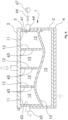
- the side wall 11 of the stamp mold half 3 can have a fluid inflow opening 61 and a fluid outflow opening 62 and the webs 12 can have fluid throughflow openings 63 ( 6 ).
- a fluid flow connection 64 is provided at the fluid inflow opening 61 and is connected to a fluid source 67 via a valve 66 .
- a fluid return connection 65 is provided at the fluid outflow opening 62 which—depending on the fluid used and depending on the process management—leads to the outside, the environment or, possibly via a treatment device, back to the fluid source 67 .
- a tempering fluid can be passed through the cavities 15 of the stamp mold half 3, for example to preheat the tool 1, to cool the mold cavity 13 or a particle foam body located therein, or in general to achieve a desired temperature control.
- trimming bodies 30, 50 Depending on the type and arrangement of the trimming bodies 30, 50 used (cf. Figs. 3 , 5 ) be arranged in the upper area of the cavities 15 or in the lower area of the cavities 15, so that a flow through the tempering fluid is not impeded by the trimming bodies 30, 50. If the fluid flow openings 63 are arranged both in the upper area and in the lower area of the cavities 15, as in the exemplary embodiment shown, different types of trimming bodies 30, 50 can be used as an alternative.
- the fluid inflow and outflow openings 61, 62 are preferably at the level of the fluid through-flow openings 63 or, if the fluid through-flow openings 63 are arranged both in the upper region and in the lower region of the cavities 15, at a level which lies between the heights of the fluid through-flow openings 63 . If a trimming body 30 of fixed geometry is so large that it protrudes into the area of the fluid flow openings 63 , transverse bores can be provided in such a trimming body 30 at the height of the fluid flow openings 63 .
- the fluid inflow and outflow openings 61, 62 and the fluid flow openings 63 are connected by small tubes or the like are. Even if the fluid inflow and outflow openings 61, 62 are provided on opposite sides of the stamp mold half 3 in the exemplary embodiment shown, they can also be arranged on the same side or on adjacent sides depending on the fluid routing inside the stamp mold half 3.
- a seal can be provided on the contact surface of the second capacitor plate 5, the seal being an edge seal on the side of the second mold half 3 or a surface seal on the side of the second capacitor plate 5 can be designed. If necessary, the pairing of materials between the second mold half 3 and the second capacitor plate 5 can also have a sufficient sealing effect during operation (ie under pressure).
- the mold halves 2, 3 are each made from a single molded part.
- the side wall 8 of the first mold half 2 can be attached to the bottom wall 7 .
- the bottom wall 7 of the first mold half 2 can be omitted if a sufficient seal is ensured between the side wall 8 and the first capacitor plate 4 in use (i.e. under pressure). This can be accomplished by a specially provided seal or by the pairing of materials between the first mold half 2 and the first capacitor plate 4 .
- the capacitor plates 4 , 5 are not part of the tool 1 .
- one or both of the capacitor plates 4 , 5 can be part of the tool 1 .
- the bottom wall 7 of the female mold half 2 can have the first capacitor plate 4 or can first capacitor plate 4 form the bottom wall 7 of the female mold half 2 .
- the first capacitor plate 4 can be attached to the side wall 8 of the female mold half 2 (e.g. screwed, glued, cast on, etc.) or integrated into the bottom wall 7 of the female mold half 2 (e.g. cast in, inserted in a pocket, etc. ) be.
- the openings 14 opening into the cavities 15 are provided at the upper edge of the stamp mold half 3 in the exemplary embodiments shown, the invention is not restricted to this. Rather, in variant embodiments, the openings 14 can also be provided in a side wall 11 of the stamp mold half 3, while the upper side of the stamp mold half 3 is closed. Openings 14 can also be provided in the webs 12 in order to get from one side into regions of the stamp mold half 3 lying further inwards.
- the second capacitor plate 5 can be connected to the stamp mold half 3 or can form a component with it.
- the second capacitor plate 5 can be attached to the side wall 11 of the stamp mold half 3 (e.g. screwed, glued, cast on, etc.) or integrated into a cover wall (if present) of the stamp mold half 3 (e.g. cast, inserted in a pocket , etc.).
- the side walls 8, 11 of the mold halves 2, 3 are formed from an electrically conductive material and that they are conductively connected to the capacitor plates 4, 5 or are formed in one piece. If the side walls 8, 11 of both mold halves 2, 3 are designed to be electrically conductive, they are coated with an electrically insulating layer, in particular a plastic layer, at least in the areas in which they touch.
- the peripheral side wall 8 is preferably not electrically conductive, e.g. made of plastic, so that there are no very small distances between the capacitor plates at the edge area, which would lead to locally very strong electric fields.
- the representation of the geometry of the mold halves 2, 3, the mold cavity 13 and the cavities 15 is purely exemplary and is entirely dependent on the type and shape of a particle foam body to be produced.
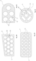
- the cavities 15 can also be rectangular or square and arranged in the manner of a matrix of, for example, two rows of four cavities 15 each ( Figure 2A ).
- the cavities 15 can be more or less dense and the cavities 15 can also have different cross-sectional shapes and sizes.
- the cavities can also be hexagonal in cross section ( Figure 2B ) or circular ( Figure 2C or more densely packed 2D ) or be shaped differently.
- the cavities 15 can, for example, be like a piece of cake ( Figure 2E ), or surrounding a circular cavity 15 in the manner of a ring segment (Fig. 2F).
- the cross-sectional shapes of the mold half 3 shown in the figures are entirely exemplary.
- the mold half 3 can be made in one piece with the cavities 15 and in one operation, for example by a casting process.
- the cavities 15 can also be subsequently incorporated into the mold half 3, for example by drilling from a solid block.
- the female mold half (first mold half) 2 can also be designed with cavities in a corresponding manner, in addition to or as an alternative to the stamp mold half 3.
- the upper capacitor plate 5 is provided with a circumferential edge web which surrounds the side wall 11 of the stamp mold half 3 .
- This edge web can serve to center and stabilize the side wall 11, but is entirely optional and can also be omitted.
- side walls 8, 11 are each described as a single, circumferential side wall, individual sections of the side walls 8, 11 adjoining one another in the circumferential direction can also be referred to as side walls.
- the tool 1 can be designed as a cracking tool and as such used in operation in basically three different positions, an open position (not shown) in which the two mold halves 2, 3 are completely separated from one another, so that a mold made with the mold Particle foam part can be removed from the mold, an intermediate position (not shown), in which the stamp mold half 3 is inserted so far into the female mold half 2 that the mold cavity 13 is closed, but the mold cavity 13 is not yet closed to its final volume Position ( Figs. 1 , 3 , 5 , 6 ) is reduced.
- the filling opening 9 and any ventilation opening are not covered by the stamp mold half 3, so that these through-openings communicate with the mold cavity 13 and foam particles can be filled in or air can be discharged.
- the mold cavity 13 is filled with foam particles. Thereafter, the stamp mold half 3 is pressed a little further into the female mold half 2, with the foam particles located therein being compressed.
- the tool 1 can be used in a device 70 for producing particle foam parts ( 7 ).
- a device 70 for producing particle foam parts has a reservoir 71 which is connected to the tool 1 with the filling hose 72 .
- the tool 1 is arranged in a press 73, which has a press table 74, a press ram 75, a cylinder-piston unit 76 for moving the press ram 75 and a stable frame 77 on which the cylinder-piston unit 76 and the press table 74 are attached.
- the press punch 75 is formed of an electrically conductive metal plate.
- the press ram 75 is connected to a wave generator 79 via a wave line 78, for example in the form of a coaxial cable.
- the press table 74 has an electrically conductive metal table top which is connected to ground via an electrically conductive base plate.
- the tool 1 is initially in an intermediate position.
- the stamp mold half 3 is inserted so far into the female mold half 2 that the mold cavity 13 is essentially closed.
- the tool 1 is inserted into the press 73 in this intermediate position.
- the filling hose 72 is connected to the filling opening 9 of the tool 1.
- Foam particles are supplied to the mold cavity 13 from the storage container 71 . If the mold cavity 13 is completely filled with foam particles, then the cylinder/piston unit 76 is actuated in order to press the two platens 13, 16 and thus the two mold halves 2, 3 together. The tool 1 is thus brought into the closed position. As a result, the foam particles located in the mold cavity 13 are compressed.
- the filling opening 9 of the matrix mold half 2 is covered by the stamp mold half 3 and thus closed.
- the filling hose 72 can then be pulled off the tool 1.
- a plug which has a similar dielectric constant as the side wall 8 can then be inserted into the filling opening 9 .
- the wave generator 79 In the compressed or closed state of the tool 1, the wave generator 79 generates an electromagnetic high-frequency signal (RF or microwave signal) which is applied via the waveguide 78, the press stamp 75 to the upper capacitor plate 5 of the stamp mold half 3.
- the waveguide 78 can be hollow and can have a core.
- the lower capacitor plate 4 of the female mold half 2 is connected to ground via the press bed 74 .
- the capacitor plates 4, 5 are electrically insulated from one another by the electrically non-conductive base bodies of the mold halves 2, 3, so that they form a plate capacitor which surrounds the mold cavity 13. Through the electromagnetic generated in this way Field, the foam particles are heated and welded together to form a particle foam part.
- the press 73 can be opened so that the tool 1 can be removed. If the tool has locking devices, it can be removed in the closed state. It can then be cooled by suitable cooling means such as a fan. While the tool 1, in which a particle foam part has already been formed, is being cooled, another tool 1 can be inserted into the press 73.
- the two mold halves 2, 3 are loosened, if necessary, the stamp mold half 3 is lifted off, and the particle foam part can be removed from the mold accordingly.
- the capacitor plates 4 , 5 are part of the device 70 and can be used for a large number of tools 1 . In particular, they also serve as pressing plates in the device 70. In this context, it is also irrelevant whether the tool 1 is in 1 Etc. shown orientation from above and below or vice versa between the capacitor plates 4, 5 is inserted.
- both mold halves 2, 3 are formed with cavities 15 for trimming the respective mold halves in order to influence an electromagnetic field within the mold cavity 13 ( 12 ).
- the first mold half 2 is basically constructed analogously to the second mold half 3 in this respect, so that the webs 12 and the side wall 8 of the first mold half 2 form supports for the first capacitor plate 4 .
- the webs 12 are also not formed in one piece with the mold halves 2, 3 as in previous exemplary embodiments, but are used as independent components in corresponding grooves on the side of the boundary walls 10 facing away from the mold cavity 13. If necessary, corresponding, vertically running grooves can also be provided in the inner surfaces of the side walls 8, 11 of the mold halves 2, 3 in order to give the webs 12 support. Alternatively or additionally, the webs 12 can also be glued, welded, or clamped between the side walls 8, 11.
- the invention is also not limited to the crack cracking process.
- the mold halves 2, 3 are not designed as punches and dies, but abut one another at the front with their side walls 8, 11.
- the side walls 8, 11 have gradations 120 that match one another, in order to seal off the mold cavity 13 when the process pressure builds up.
- the tool 1 of this exemplary embodiment a filling opening 121, which remains free when the mold 1 is closed and to which a filling injector 122 can be connected, with which the foam particles are introduced into the mold cavity 13.
- the inventors of the present application made simulations on the effect of the present invention.
- a simplified model was considered using a substitute image ( 8 ).
- the capacitor plates 4, 5 are connected to a voltage source 80, which corresponds to a polarization state of the wave generator 79. Accordingly, the capacitor plates 4, 5 are oppositely charged.
- an electromagnetic field E forms between the capacitor plates 4, 5, the strength of which depends on the respective permittivities of the regions 81, 82, 83.
- Field strength profiles of the electromagnetic field E between the capacitor plates 4, 5 can be calculated with this model. If required or for further approximation of specific forms of the tool 1 or a tool system with trimming bodies, further areas can be defined.
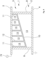
- a model provides in section two side walls 8 of the first mold half 2 extending between the capacitor plates 4, 5 ( 9 ).
- a bottom wall (Bz. 7 in Figs. 1 , 3 , 5 , 6 ) is not provided in this model.
- the capacitor plates 4, 5 project laterally beyond the side wall 8 of the first mold half 2.
- the first capacitor plate 4 is grounded, the second capacitor plate 5 is connected to a wave generator 79.
- a boundary wall 10 of the second mold half 3 extends between the side walls 8 in an oblique straight line.
- Side walls 11 and webs 12 ie, supports 11, 12 in the sense of the invention) lead from the boundary wall 10 to the second capacitor plate 5 in order to leave cavities 15 between them (on average six cavities 15, without loss of generality).
- a mold cavity 13 which is wedge-shaped in this model, is defined between the first capacitor plate 4, the side walls 8 of the first mold half 2 and the boundary wall 10.
- the practically vanishing field weakening in the supports 11, 12 is surprising at first, since a field weakening in the magnitude of the boundary wall 10 would initially be expected due to the dielectric properties. Such a field weakening in the supports 11, 12 would also lead to a significant inhomogeneity of the field in the mold cavity 13 compared to the supports 11, 12 and would be difficult to handle.
- the inventors of the present application have determined through theoretical considerations, simulations and tests that such an effect does not exist, which makes the implementation of the invention practicable. A theoretical explanation for this behavior becomes possible if the arrangement between the capacitor plates 4, 5 is divided into narrow elements in the width direction and the elements are first considered individually and then superimposed.
- a development of the invention provides, as a further exemplary embodiment, that the trimming of the mold half can be changed during a foaming process.
- the foaming process here includes a period of time from the introduction of the foam particles to the removal of the particle foam body. Of course, this does not rule out that the trimming is also changed before and/or after the foaming process.
- a trimming body in the form of a fluid is used and this fluid is supplied to the cavity or cavities and/or removed from the cavity or cavities via trimming fluid lines.
- the mold half and/or the associated capacitor plate is/are designed in such a way that this can also take place during a foaming process, ie in particular when the mold is mounted between the capacitor plates and/or when the mold cavity is closed.
- the trimming fluid can also be supplied/removed via a trimming fluid supply unit, which is arranged between the mold half and the capacitor plate.
- a trimming fluid supply unit for example, water, an oil or a viscous liquid (e.g. gel) can be used as the trimming fluid.
- a fluid with a low relative permittivity is preferably selected as the trimming fluid.
- bores 130 are provided in the side walls 11 and the webs 12, which communicate with the cavities 15 in the second mold half 3 ( 13 ).
- the bores 130 are each formed from one side through a side wall 11 continuously over the entire length or width of the mold half 3 through all webs 12 lying in a line to the last cavity 15 lying on the line and each form at least an opening 131 in a side wall 11 from.
- a trimming fluid supply port 132 is attached with a valve, which has a feed pump 133 with a Trimming fluid reservoir 134 is connected.
- a valved trim fluid drain port 135 which is connected to the trim fluid reservoir 133 via a trim fluid drain pump 136 .
- a valved supply air connection 137 is attached to another of the openings 131 and a valved venting connection 138 is attached to a last of the openings 131 .
- the supply air connection 137 and the venting connection can each be equipped with a fluid barrier.
- the air supply port 137 may be connected to a compressed air tank or air supply pump, and the vent port 138 may be connected to a vacuum tank or vacuum pump.
- the trimming fluid supply connection 132 and the venting connection 138 are opened and the feed pump 133 is put into operation in order to supply trimming fluid from the trimming fluid reservoir 134 to the cavities 15 .
- All cavities 15 are reached by the communicating connection via the bores 130 . Excess air can escape via the vent port 138 .
- the trimming fluid supply port 132 and the venting port 138 are closed and the charge pump 133 is turned off.
- the amount of trimming fluid can be set in advance. Reaching the predetermined quantity can be determined, for example, by measuring the flow at the feed pump 133 or by designing it as a metering pump. Alternatively, complete filling of the cavities 15 can be detected by triggering a fluid blockage of the vent port 138 .
- the trimming fluid discharge connection 135 and the air supply connection 137 are opened and the trimming fluid discharge pump 136 is put into operation in order to withdraw trimming fluid from the mold half 3 and feed it back to the trimming fluid reservoir 134.
- the trimming fluid can also be circulated. All cavities 15 are reached by the communicating connection via the bores 130 .
- the cavities 15 can be kept pressureless via the air supply connection 137 or the removal of trimming fluid can be supported via compressed air.
- the trim fluid discharge port 135 and the supply air port 137 are closed and the trim fluid drain pump 136 is switched off.
- the trimming fluid supply connection 132 and/or the trimming fluid discharge connection 135 can each optionally be configured without a valve if the respective pump 133, 136 has corresponding blocking devices.
- the pumps 133, 136 may be integrated into or attached to the respective trimming fluid ports 132, 135, or the valves of the trimming fluid ports 132, 135 may be integrated into or attached to the respective pumps 133, 136.
- the bores 130 each end in the last cavity 15 on the bore line.
- the bores 130 can also go beyond the last cavity 15 and through the side wall 11 adjoining there. This increases the connection options and also enables adaptation to the conditions on the system side. Unneeded openings in the side walls 11 can be closed with blind plugs.
- the bores 130 can be formed on a first level in relation to a height of the mold half 3 and further bores (not explicitly shown) can be formed on a second, higher level, with the trimming fluid connections 132, 135 at the openings 131 are connected on the first level and the supply air port 137 and the exhaust port 138 are connected on the second level. Unused openings in the side walls 11 are then closed by blind plugs.
- passages in the side walls 11 and the webs 12 can also be substituted when the mold half 3 is formed by an additive manufacturing process. In this case, additional connections can also be created in the webs 12 without requiring a bore from the outside. The formation of unnecessary openings in the side walls 11 can also be avoided.
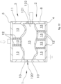
- respective covers 140 are arranged in the cavities 15 of the upper mold half 3, which divide the respective cavity into a trimming space 142 below the cover 140 and a pressure space 141 above the cover 140 ( 14 ).
- the lids 140 are urged upward by respective compression springs 148 located in the trimming space 142 .
- Trimming fluid lines 143 protrude through respective bores in the covers 140 and in the capacitor plate 5 adjoining the upper mold half 3 into the trimming space 142 of each cavity 15.
- the trimming fluid lines 143 converge outside the tool and are connected to a trimming fluid valve 144, which is designed here as a directional control valve is.
- trimming fluid can be fed from a trimming fluid reservoir 134 into the trimming fluid line 143 via the trimming fluid valve 144 via a trimming fluid feed pump 133 .
- the trimming fluid line 143 is connected to a return line into the trimming fluid reservoir 134 .
- all connections of the trimming fluid valve 144 are blocked.
- Compressed air lines 145 protrude through further bores in the capacitor plate 5 into the pressure chamber 141 of each cavity 15.
- the compressed air lines 145 converge outside of the tool and are connected to a compressed air valve 146, which is designed here as a directional control valve.
- the compressed air line 145 In a first switching position (neutral position), the compressed air line 145 is connected to the atmosphere.
- the compressed air line 145 is connected to a compressed air tank 147 .
- the trimming fluid valve 144 is switched from the neutral position to the first switching position, with the compressed air valve 146 being connected to the atmosphere in the first switching position, and the feed pump 133 is activated to pump trimming fluid from the trimming fluid reservoir 134 to the trimming spaces in the cavities 15 via the trimming fluid lines 143 . Due to the individual connection via the trimming fluid lines 143 to the trimming fluid feed pump 133, all of the cavities 15 are filled with trimming fluid simultaneously and rapidly. Excess air can escape via the compressed air valve 146 when the covers 140 in the cavities 15 are pushed up. When the cavities 15 are filled with a predetermined amount of trim fluid, the trim fluid valve 144 is switched to the neutral position, thus blocking a flow of trim fluid and the feed pump 133 is switched off.
- the amount of trimming fluid between the individual cavities 15 can adjust to one another. Reaching the predetermined quantity can be determined, for example, by measuring the flow at the feed pump 133 or by designing it as a metering pump.
- the trimming fluid valve 144 is switched to the second switching position and the compressed air valve is switched to the second switching position in order to apply compressed air to the pressure spaces 141 of the cavities 15.
- the compressed air in the pressure chambers 141 presses the lids 140 downwards, as a result of which the trimming fluid located in the trimming chambers 142 is pressed into the trimming fluid lines 143 and out of the mold half 3 and is fed back to the trimming fluid reservoir 134 .
- the trimming fluid can also be circulated. Due to the individual connection via the compressed air lines 145 to the compressed air tank 147, all cavities 15 are emptied simultaneously and quickly. When this process is complete, the trim fluid valve 144 is switched to the neutral position and the air pressure valve 146 is returned to atmosphere.
- trim fluid lines 143 may be individually connected to respective trim fluid valves for each cavity 15 .
- the trim fluid valves can be attached to the condenser plate 5 or housed or combined in a separate control unit.
- the trimming fluid valves can be constructed like the trimming fluid valve 144 and can be connected to the other paths via a common trimming fluid feed line to the trimming fluid feed pump 133 or via a common trimming fluid return line to the trimming fluid reservoir 134.
- the compressed air lines 145 can be individually connected to respective compressed air valves for each cavity 15 .
- the compressed air valves can be attached to the condenser plate 5 or housed or combined in a separate control unit.
- the compressed air valves can be constructed like the compressed air valve 146 and with the respective other paths via a common compressed air collection line with compressed air tank 147 or, if necessary, connected to the atmosphere via a common vent line.
- sections of the trimming fluid lines 143 and/or the compressed air lines 145 can be attached separately to an inside and/or to an outside of the capacitor plate 5 .
- the bores in the capacitor plate 5 can be provided with threads, for example, so that an inner part of the trimming fluid lines 143 and/or the compressed air lines 145 can be screwed to the inside of the capacitor plate 5 and an outer part of the trimming fluid lines 143 and/or the compressed air lines 145 to the Outside of the capacitor plate 5 can be screwed.
- an inner portion of the trim fluid lines 143 may be a piece of tubing with a threaded end.
- an inner part of the trimming fluid lines 143 can be of different lengths depending on the depth of the cavity 15 to be supplied.
- a connection plate (not shown in detail) can be provided, which carries sections of the trimming fluid lines 143 and/or the compressed air lines 145 pointing into the cavities 15 .
- the sections of the trimming fluid lines 143 can be designed, for example, as pipe pieces that can be firmly connected to the connection plate or can be attached to it, for example by screwing, plugging and/or gluing in corresponding bores.
- the sections of the compressed air lines 145 can be designed and attached in the same way or they can just be openings of corresponding bores, since the compressed air lines 145 do not have to protrude into the cavities 15 .
- connection plate 5 Holes in the capacitor plate 5 can be aligned with holes in the intermediate plate, so that the sections of the trimming fluid lines 143 and/or the compressed air lines 145 that are attached to the connection plate can be plugged through the holes in the capacitor plate 5 from the outside, so that a reliable Alignment of the connection plate and the capacitor plate is given.
- the external parts of the trimming fluid lines 143 and the compressed air lines 145 are then to be attached to the outside of the connection plate.
- the connection plate can be made of metal or plastic, for example.
- the connection plate can be produced conventionally by providing a plate and pieces of pipe, if necessary corresponding machining and assembly. Alternatively, the connection plate together with any pipe sections of the lines 143, 145 can be formed in one piece by an additive manufacturing process.
- connection plate can be arranged/can be arranged between the mold half 3 and the capacitor plate 5 .
- holes in the capacitor plate 5 can align with holes in the intermediate plate, although the external parts of the trimming fluid lines 143 and the compressed air lines 145 must then be attached to the outside of the capacitor plate 5 .
- short pieces of pipe can be used as sections of the compressed air lines 145 on the outside of the connecting plate be arranged and be plugged into the corresponding holes in the capacitor plate, so that a reliable alignment of the connection plate and the capacitor plate is also given in this case.
- connection plate is made of metal in this variant, it can act as a functional part of the capacitor plate 5 with regard to the generation of the electromagnetic field.
- connection plate is made of plastic in this variant, it can contribute to the dielectric effect of the mold half 3.
- a connection plate 150 can be provided ( 15 ) which receives or includes portions of the trimming fluid lines 143 and the compressed air lines 145, with the mold half facing portions of the lines 143, 145 opening in the face of the port plate 150 and the outward facing portions of the lines 143, 145 at one or more side edges Open the side edges of the connection plate 150.
- a switching unit with valves can also be arranged there.
- connection plate 150 can have the shape of a cuboid with an inner surface 151, an outer surface 152 opposite this, a first side surface 153, which connects the inner surface 151 and the outer surface 152, a second side surface 154, which adjoins the first side surface 153, and further side surfaces, which are opposite to the first side surface 153 and the second side surface 154, respectively.
- the inner surface 151 has a first set of bores 155 each carrying a piece of tubing 156 and a second set of bores 157 .
- the first side surface 153 carries, in a plane close to the outer surface 152, a group of third bores 158 which each meet a row of the first group of bores 155.
- the second side surface 154 carries in a plane close to the inner surface 151 a group of fourth bores 159 which each meet a row of the second group of bores 157 .
- the first group of holes 155 is arranged diagonally offset from the second group of holes 157 and the third group of holes 158 is arranged offset in height from the fourth group of holes 159, so that the holes 155 of the first group are only connected to holes 158 of the third group communicate and vice versa and the holes 157 of the second group communicate only with holes 159 of the fourth group and vice versa.
- the bores 155 of the first group with pipe sections 156 and the bores 158 of the third group each form sections of the trimming fluid line 143 and the bores 157 of the second group and the bores 159 of the fourth group each form sections of the compressed air line 145 (cf. 14 ), and the trimming fluid line 143 does not overlap with the compressed air line 145.
- All holes 155, 157, 158, 159 are preferably blind holes. If they are designed as through holes, one side should be sealed with blind plugs.
- the bores 158 of the third group can be connected to one another by a first collecting bore in the second side surface 154 or the side surface opposite thereto, and the bores 159 of the fourth group can be connected to one another by a second collecting bore in the first side surface 153 or the side surface opposite thereto Side surface are connected to each other. Then the bores 158, 159 of the third and fourth group can be closed by blind plugs, and only the first collecting bore needs to be connected to the trimming fluid valve 144 and the second collecting bore to the compressed air valve 146.
- the specific arrangement of the bores 155, 157, 158, 159 in 15 is to be understood entirely as an example.
- the bores 158, 159 of the third and fourth group can also be formed on a single side surface 153 or 154, in which case even on a single plane, without the trimming fluid line 143 and the compressed air line 145 overlapping.
- the arrangement shown has the advantage that the media trimming fluid and compressed air are separated from one another in terms of connection technology.
- connection plate 150 described here.
- a cover plate 160 can also be provided, which is arranged between the mold half 3 and the capacitor plate 5 and which has a number of projections which protrude into the cavities 15 and limit their volume ( 16 ).
- one or more bores 130 can be provided in the upper mold half 3, which forms a connection opening for trimming fluid in at least one side wall 11 and cuts through at least one of the webs 12 in order to fluidly connect several cavities 15 of the mold half 3.
- the arrangement of the bores is fundamentally arbitrary, as long as trimming fluid can be supplied and removed or passed through all cavities.
- the protrusions 161 are preferably sized so that the volumes remaining in the cavities 15 are of substantially equal height, but again this is optional and can be tailored to suit requirements.
- the protrusions 161 can be interchangeable elements of different heights attachable to the top plate.
- the bore(s) 130 is/are formed in such a way that they lie in the area of the volumes left by the projections 161, and also in such a way that all the volumes remaining in the cavities 15 can be filled with trimming fluid and emptied again as completely as possible.
- an opening formed through the bore 130 in the right side wall 11 at the top can serve as a supply connection for trim fluid and an opening formed through the bore 130 in the left side wall 11 at the bottom can serve as a drain connection for trim fluid, so that when trim fluid is both introduced and withdrawn, the Gravity exploited can be.
- the cover plate 160 can be produced by a casting method, by deep-drawing a plate, by milling and/or drilling from the solid, or by an additive method.
- additive manufacturing 3D printing
- no bores are required; instead, all connection and connection openings can be formed in one go with the additive structure of the cover plate 160.
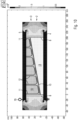
- covers 170 can be provided, each of which is arranged in a height-adjustable manner in one of the cavities 15 and can be individually adjusted in height via a plunger 171 and a lifting drive 172 attached to the upper capacitor plate 5 ( 17 ).
- the plungers 171 are mounted in bores 173 in the upper capacitor plate.
- the tappets 171 can be designed as threaded rods, which are screwed into bores 173 designed with an internal thread, and can be rotated via a driving groove (not shown in detail) by the lifting drive 172 designed as a rotary drive, so that by turning in the (threaded) bores 173 a height adjustment can be effected.
- Other height adjustment devices are well known in the art and may alternatively be used as required.
- At least one bore 130 is provided for supplying the cavities 15 with trimming fluid; the above explanations apply in this regard.
- the lids can individually limit the volume of the cavities 15 ( 16 ). In this way, the relative permittivity of the mold half can not only be adjusted locally, but can also be changed during the foaming process.
- an expulsion of the trimming fluid via the bore 130 can also be assisted by closing the cover.
- one of the mold halves 2, 3 can also have a side opening or a plurality of side openings 14, into which a mold body 30 can be inserted and removed from the side ( 18A , direction of movement 180).
- the shaped body 30 can be comb-shaped with a base 181 and a plurality of cuboid prongs 182 ( Figure 18B ).
- several individual cuboid shaped bodies 30 can also be used, which can be moved into and out of the cavities 15 in an individually controlled manner.
- a tool system with such mold halves 2, 3 and mold body 30 is particularly, but not only, suitable for the production of particle foam boards with the help of electromagnetic waves.
- several shaped bodies 30 can be provided in the form of plates of the same shape as described above but of a lower height, which together fill the cavities 15 and can be moved in and out of the cavities 15 in an individually controlled manner ( Figure 18C ).
- Pumps 133, 136, connections 132, 135, 137, 138, valves 144, 146, tanks 134, 147, lines 143, 145 and other piping can be individual and in any arrangement and/or be a sub-combination part of a trimming fluid supply device.
- a controller for controlling all process operations described, including the activation of motors, pumps, valves and the provision of suitable sensors for providing process and status data for the controller as required, is self-evident and requires no further explanation.
Description
Die vorliegende Erfindung betrifft ein Werkzeug, ein Werkzeugsystem und ein Verfahren zum Herstellen von Partikelschaumstoffteilen.The present invention relates to a tool, a tool system and a method for producing particle foam parts.
Das Werkzeug und das Werkzeugsystem zum Herstellen von Partikelschaumstoffteilen sind zum Herstellen der Partikelschaumstoffteile unter Verwendung von elektromagnetischen Wellen vorgesehen, wobei mittels der elektromagnetischen Wellen Schaumstoffpartikel zu einem Partikelschaumstoffteil verschweißt werden. Die zum Verschweißen notwendige Energie wird mittels der elektromagnetischen Wellen an die Schaumstoffpartikel angelegt.The tool and the tool system for producing particle foam parts are provided for producing the particle foam parts using electromagnetic waves, with foam particles being welded to form a particle foam part by means of the electromagnetic waves. The energy required for welding is applied to the foam particles by means of electromagnetic waves.
Seit langem wird versucht, Schaumstoffpartikel mittels elektromagnetischer Wellen zu Partikelschaumstoffteilen zu verschweißen. So gehen entsprechende Verfahren beispielsweise aus der
In der
Ein ähnliches Verfahren geht aus der
In der
Auch in den letzten Jahrzehnten gab es erhebliche Anstrengungen, Schaumstoffpartikel mittels elektromagnetischer Wellen zu verschweißen. So sind entsprechende Verfahren in der
Aus der
In der
Trotz dieser seit langem anhaltenden erheblichen Anstrengungen gibt es am Markt keine Maschinen, mit welchen Schaumstoffpartikel mittels elektromagnetischer Wellen verschweißt werden. In der kommerziellen Benutzung sind ausschließlich Maschinen, welche die Schaumstoffpartikel mittels Dampf verschweißen.Despite these considerable efforts, which have lasted for a long time, there are no machines on the market with which foam particles are welded by means of electromagnetic waves. Only machines that weld the foam particles using steam are in commercial use.
Es gibt keine serienreifen Maschinen zum Verschweißen von Schaumstoffpartikeln, obwohl die hiermit verbunden Vorteile seit langem bekannt sind. Dies sind vor allem
- ein effizienterer Energieeintrag,
- nach dem Verschweißen sind die Partikelschaumstoffteile trocken und können sofort weiter verarbeitet werden,
- das Erhitzen erfolgt von innen nach außen, so dass der Innenbereich der Schaumstoffpartikel wesentlich besser verschweißt werden kann, und
- die Geräte zur Erzeugung von Dampf entfallen, welche im Vergleich zu einem Generator für elektromagnetische Wellen wesentlich aufwändiger sind.
- a more efficient energy input,
- after welding, the particle foam parts are dry and can be further processed immediately,
- the heating takes place from the inside out, so that the inner area of the foam particles can be welded much better, and
- the devices for generating steam are eliminated, which are much more complex compared to a generator for electromagnetic waves.
Die Anmelderin der vorliegenden Patentanmeldung hat die Vorrichtungen zum Verschweißen von Schaumstoffpartikeln mittels elektromagnetischer Wellen und die entsprechenden Verfahren derart weiterentwickelt, dass sie in der Lage ist, größere Stückzahlen von Schaumstoffpartikeln mittels seriennaher Prototypen durch Verschweißen der Schaumstoffpartikel mittels elektromagnetischer Wellen herzustellen. Diese Vorrichtungen und Verfahren beruhen auf der in der
Hiermit ist es gelungen, eine gleichmäßige Verschweißung in Partikelschaumstoffteilen mit unterschiedlicher Form zu erzielen. Je komplexer die Form des Partikelschaumstoffteils ist, desto schwieriger ist es, die Schaumstoffpartikel gleichmäßig zu verschweißen. Seit Jahrzehnten ist es bekannt, dass man derartige Schaumstoffpartikel in einem Plastikbecher mit etwas Wasser in ein herkömmliches Haushaltsmikrowellengerät stellen kann und man damit eine gute, gleichmäßige Verschweißung erzielt. Sind die herzustellenden Partikelschaumstoffteile jedoch größer oder komplexer geformt oder stark konturiert oder mit unregelmäßiger Dicke (gemessen in einer Richtung senkrecht zu den Kondensatorplatten, d.h., in Ausbreitungsrichtung des elektromagnetischen Feldes), dann ist es schwierig, an allen Stellen eine gleichmäßige Verteilung des elektromagnetischen Feldes zu erzielen. Die Probleme haben unterschiedlichste Ursachen. Einerseits haben elektromagnetische Wellen prinzipbedingt nicht überall die gleiche Energiedichte. Je kürzer die Wellenlänge ist, desto größer sind die lokalen Schwankungen. Andererseits werden die elektromagnetischen Wellen durch das Material des Werkzeuges, das das Formnest begrenzt, beeinflusst. Hier gibt es unterschiedliche Effekte. Einerseits kann ein Teil der Energie der elektromagnetischen Wellen durch das Material des Formwerkzeugs absorbiert werden. Andererseits fungiert dieses Material als Dielektrikum, das derart polarisiert wird, dass es ein zu den elektromagnetischen Wellen entgegengesetztes elektromagnetisches Feld erzeugt. Hierdurch wird die Energiedichte der elektromagnetischen Wellen verschoben und kann lokal im Formnest konzentriert werden. Dies haben die Erfinder der vorliegenden Erfindung erstmals bei der Entwicklung der vorliegenden Erfindung berücksichtigt.With this it has been possible to achieve uniform welding in particle foam parts with different shapes. The more complex the shape of the particle foam part, the more difficult it is to weld the foam particles evenly. It has been known for decades that such foam particles can be placed in a plastic cup you can put some water in a conventional household microwave oven and get a good, even weld. However, when the particle foam parts to be produced are larger or more complex in shape, or highly contoured, or of irregular thickness (measured in a direction perpendicular to the capacitor plates, i.e., in the direction of propagation of the electromagnetic field), it is difficult to achieve uniform electromagnetic field distribution at all locations achieve. The problems have different causes. On the one hand, due to the nature of the principle, electromagnetic waves do not have the same energy density everywhere. The shorter the wavelength, the larger the local fluctuations. On the other hand, the electromagnetic waves are influenced by the material of the tool that delimits the mold cavity. There are different effects here. On the one hand, part of the energy of the electromagnetic waves can be absorbed by the material of the mold. On the other hand, this material acts as a dielectric, which is polarized in such a way that it creates an electromagnetic field opposite to the electromagnetic waves. As a result, the energy density of the electromagnetic waves is shifted and can be concentrated locally in the mold cavity. The inventors of the present invention took this into account for the first time when developing the present invention.
Weiterhin kann auch das Material, aus dem die Schaumstoffpartikel ausgebildet sind, einen Einfluss auf das elektromagnetische Feld haben, so dass bei Verwendung von unterschiedlichen Materialien dasselbe Werkzeug unterschiedlich wirkt.Furthermore, the material from which the foam particles are formed can also have an influence on the electromagnetic field, so that when different materials are used, the same tool acts differently.
Beim RF-Schäumen von komplexen Geometrien ist es daher erstrebenswert, wenn das elektrische Feld in allen Bereichen des Formteils möglichst konstant oder gleichmäßig ist. Es gibt Ansätze, dies beispielsweise mit Verformung von Elektroden und Variation von Werkzeugwandstärken zu erreichen. Das ist aber mit der Anwendung von sehr komplexen Simulationsprogrammen verbunden. Die Schwierigkeit liegt dabei daran, dass sich die relative Permittivität von Werkzeugmaterial und Partikelschaum stark unterscheiden, beispielsweise um einen Faktor 2 bis 5.When RF foaming complex geometries, it is therefore desirable if the electric field is as constant or even as possible in all areas of the molded part. There are approaches to achieve this, for example, by deforming electrodes and varying tool wall thicknesses. However, this involves the use of very complex simulation programs. The difficulty lies in the fact that the relative permittivity of the tool material and particle foam differ greatly, for example by a factor of 2 to 5.
Ein weiteres Problem besteht darin, dass es praktisch unmöglich ist, die Werkzeuge zum RF-Schäumen nachträglich zu optimieren, wenn beispielsweise das elektrische Feld in manchen Bereichen verstärkt werden soll.Another problem is that it is practically impossible to post-optimize RF foaming tools, for example to increase the electric field in some areas.
Da die Erwärmung mit einem RF-Feld von innen nach außen geht, wird die Verschweißung von äußeren Partikelschichten schlechter als im Kern, und die Oberfläche kann rau bleiben. Um dieses zu verbessern wurden bisher Heiz- und Kühlkanäle im Werkzeug vorgesehen.Because heating with an RF field is from the inside out, welding of outer layers of particles becomes poorer than at the core, and the surface can remain rough. In order to improve this, heating and cooling channels were previously provided in the tool.
Aus verfahrenstechnischen Gründen kann es sinnvoll sein, wenn die Schaumpartikel mit Wasser als Wärmeübertragungsmedium versetzt in das Formnest eingebracht werden. Beim Verschweißen kann das Wasser dann aus dem Formnest gedrückt werden. Dadurch kann sich die mittlere relative Permittivität im Formnest ändern und damit auch die lokale elektrische Feldstärke. Die Steuerung eines solchen Prozesses ist schwierig.For process engineering reasons, it can be useful if the foam particles are introduced into the mold cavity mixed with water as a heat transfer medium. During welding, the water can then be pressed out of the mold cavity. This can the average relative permittivity in the mold cavity changes and with it the local electric field strength. Controlling such a process is difficult.
In einer Vorrichtung zum Herstellen von Partikelschaumstoffteilen will man unterschiedliche Partikelschaumstoffteile herstellen. Hierzu muss man die entsprechenden Werkzeuge, welche ein Formnest definieren, in dem die Partikelschaumstoffteile ausgeformt werden, austauschen. Dies ist bereits von herkömmlichen Vorrichtungen zum Herstellen von Partikelschaumstoffteilen, welche die Schaumstoffpartikel mittels Dampf verschweißen, hinlänglich bekannt. Die Erfinder der vorliegenden Erfindung haben jedoch erkannt, dass anders als beim Verschweißen von Schaumstoffpartikel mittels Dampf beim Verschweißen mittels elektromagnetischer Wellen die Funktion eines Werkzeuges von der Form abhängt, welche durch die Form des herzustellenden Partikelschaumstoffteils vorgegeben ist. Dies ist auch eine der Hauptursachen, wieso es trotz intensivster Versuche und Entwicklungsanstrengungen seit Jahrzehnten nie gelungen ist, Vorrichtungen zum Verschweißen von Partikelschaumstoffteilen, insbesondere solcher mit einer unregelmäßigen Form oder Dicke oder starker Konturierung, mittels elektromagnetischer Wellen zu entwickeln, die für eine Serienproduktion geeignet sind.In a device for producing particle foam parts, one wants to produce different particle foam parts. To do this, the corresponding tools, which define a mold cavity in which the particle foam parts are formed, have to be exchanged. This is already well known from conventional devices for producing particle foam parts, which weld the foam particles by means of steam. However, the inventors of the present invention have recognized that, unlike when welding foam particles by means of steam, when welding by means of electromagnetic waves, the function of a tool depends on the shape, which is predetermined by the shape of the particle foam part to be produced. This is also one of the main reasons why, despite the most intensive tests and development efforts for decades, it has never been possible to develop devices for welding particle foam parts, in particular those with an irregular shape or thickness or strong contours, using electromagnetic waves that are suitable for series production .
Der Erfindung liegt deshalb die Aufgabe zugrunde, ein Werkzeug zum Herstellen von Partikelschaumstoffteilen, sowie ein entsprechendes Werkzeugsystem zu schaffen, mit welchen auf einfache Art und Weise Schaumstoffpartikel mittels elektromagnetischer Wellen zuverlässig in hoher Qualität verschweißt werden können.The invention is therefore based on the object of creating a tool for producing particle foam parts and a corresponding tool system with which foam particles can be welded reliably and with high quality in a simple manner by means of electromagnetic waves.
Eine Aufgabe der vorliegenden Erfindung ist es insbesondere, ein Werkzeug, ein Werkzeugsystem und ein Verfahren anzugeben, das die oben genannten Nachteile und Probleme vermeidet oder zumindest verbessert.One object of the present invention is in particular to specify a tool, a tool system and a method which avoids or at least improves the disadvantages and problems mentioned above.
Eine weitere Aufgabe der vorliegenden Erfindung ist es, eine Möglichkeit zur nachträglichen Optimierung eines solchen Werkzeuges zu schaffen.A further object of the present invention is to create a possibility for subsequent optimization of such a tool.
Eine weitere Aufgabe der vorliegenden Erfindung ist es, ein Werkzeug, ein Werkzeugsystem und ein Verfahren im Hinblick auf eine gleichmäßige Qualität der Verschweißung im Querschnitt des Partikelschaumstoffteils zu verbessern.A further object of the present invention is to improve a tool, a tool system and a method with regard to a uniform quality of the welding in the cross section of the particle foam part.
Eine weitere Aufgabe der vorliegenden Erfindung ist es, eine Möglichkeit zu schaffen, eine Änderung der relativen Permittivität im Formnest während des Schäumvorgangs auszugleichen und/oder das im Formnest vorherrschende elektromagnetische Feld, insbesondere im Hinblick auf die elektrische Feldstärke, während des Schäumvorgangs zu beeinflussen.A further object of the present invention is to create a possibility of compensating for a change in the relative permittivity in the mold cavity during the foaming process and/or influencing the electromagnetic field prevailing in the mold cavity, in particular with regard to the electric field strength, during the foaming process.
Eine oder mehrere der genannten Aufgaben werden durch die Gegenstände der unabhängigen Patentansprüche gelöst. Vorteilhafte Ausgestaltungen sind in den jeweiligen Unteransprüchen angegeben.One or more of the stated objects are solved by the subject matter of the independent patent claims. Advantageous configurations are specified in the respective dependent claims.
Das erfindungsgemäße Werkzeug zum Herstellen von Partikelschaumstoffteilen durch Verschweißen von Schaumstoffpartikel mittels elektromagnetischer Wellen umfasst zwei Formhälften, welche ein Formnest begrenzen. Wenigstens eine der beiden Formhälften ist aus einem für elektromagnetische Wellen transparenten Material ausgebildet und weist eine das Formnest begrenzende Begrenzungswandung und eine oder mehrere Stützen auf, welche zum Abstützen der Begrenzungswandung an einer Kondensatorplatte auf der vom Formnest weg weisenden Seite dienen und einen oder mehrere Hohlräume der Formhälfte ausbilden.The tool according to the invention for producing particle foam parts by welding foam particles by means of electromagnetic waves comprises two mold halves which delimit a mold cavity. At least one of the two mold halves is made of a material that is transparent to electromagnetic waves and has a boundary wall delimiting the mold cavity and one or more supports which serve to support the boundary wall on a capacitor plate on the side facing away from the mold cavity and one or more cavities in the Form mold half.
Durch die Ausbildung der Hohlräume auf der von dem Formnest abgewandten Seite der Begrenzungswandung können Formhälften beliebiger Formen mit einem Minimum an Material verwirklicht werden. Daher kann die Beeinflussung des elektromagnetischen Feldes im Formnest durch das Material der Formhälfte begrenzt werden. Überraschenderweise hat sich bei Simulationen wie Versuchen herausgestellt, dass die Stützen kaum bis keine Diskontinuitäten oder Inhomogenitäten der Feldstärke im Formnest bewirken. Vielmehr mittelt sich die Feldstärke zwischen Bereichen, die den Stützen entsprechen, und Bereichen, die den Hohlräumen entsprechen, aus, und diese Mittelung oder Gleichmäßigkeit setzt sich in das Formnest fort. Mit anderen Worten liegt eine Mittelung der Permittivitäten des Materials der Formhälften und der in den Hohlräumen enthaltenen Luft vor, die überraschend homogen ist, selbst wenn das Material der Formhälfte in die darin befindlichen Hohlräume nicht homogen verteilt sind. Die Formhälften werden daher vorzugsweise so ausgebildet, dass sie eine mittlere Permittivität aufweisen, die etwa der Permittivität der zu verschweißenden Schaumstoffpartikel entspricht. Dies ergibt ein sehr homogenes elektrisches Feld, selbst, wenn das Formnest komplex konturiert ist.By forming the cavities on the side of the boundary wall facing away from the mold cavity, mold halves of any shape can be realized with a minimum of material. Therefore, the influence of the material of the mold half on the electromagnetic field in the mold cavity can be limited. Surprisingly, simulations and tests have shown that the supports hardly cause any discontinuities or inhomogeneities in the field strength in the mold cavity. Rather, the field strength averages out between areas corresponding to the supports and areas corresponding to the cavities, and this averaging or uniformity propagates into the mold cavity. In other words, there is an averaging of the permittivities of the material of the mold halves and the air contained in the cavities, which is surprisingly homogeneous, even if the material of the mold half is not homogeneously distributed in the cavities therein. The mold halves are therefore preferably designed in such a way that they have an average permittivity which approximately corresponds to the permittivity of the foam particles to be welded. This gives a very homogeneous electric field even when the mold cavity is complex contoured.
Daher lassen sich auf einfache Weise Formhälften mit ähnlichen dielektrischen Eigenschaften wie der herzustellende Gegenstand verwirklichen. Insbesondere ist eine Abstimmung der dielektrischen Eigenschaften der Formhälfte an das Partikelschaumstoffteil in überraschend einfacher Weise möglich. Wenn die dielektrischen Eigenschaften der Formhälfte in etwa denen des Partikelschaumstoffteils entsprechen, hat das auch den Vorteil, dass das elektromagnetische Feld im gesamten Bereich zwischen den Kondensatorplatten annähernd homogen ist, unabhängig von der Formgestaltung der Formhälfte bzw. des Partikelschaumstoffteils.Therefore, mold halves with similar dielectric properties as the object to be manufactured can be realized in a simple manner. In particular, the dielectric properties of the mold half can be matched to the particle foam part in a surprisingly simple manner. If the dielectric properties of the mold half roughly correspond to those of the particle foam part, this also has the advantage that the electromagnetic field is approximately homogeneous in the entire area between the capacitor plates, regardless of the shape of the mold half or particle foam part.
Das Abstützen der Kondensatorplatte durch die Stützen kann unmittelbar oder mittelbar (also mit einer Zwischenlage) erfolgen. Die Stützen können durch Seitenwände und/oder Zwischenwände realisiert sein. Die Begrenzungswandung und die Stützen können einteilig, insbesondere monolithisch ausgebildet sein. Bei manchen Formen bildet eine Kondensatorplatte bereits eine Begrenzung des Formnests. Natürlich ist es ebenso möglich, dass jede der beiden Formhälften aus dem für elektromagnetische Wellen transparenten Material ausgebildet ist und die Begrenzungswandung und die Stütze/n aufweist.The capacitor plate can be supported by the supports directly or indirectly (i.e. with an intermediate layer). The supports can be realized by side walls and/or intermediate walls. The boundary wall and the supports can be designed in one piece, in particular monolithically. In some forms forms a capacitor plate already a limitation of the mold cavity. Of course, it is also possible for each of the two mold halves to be made of the material that is transparent to electromagnetic waves and to have the boundary wall and the support(s).
Vorzugsweise ist die Begrenzungswandung der wenigstens einen Formhälfte mit im Wesentlichen konstanter Dicke ausgebildet.The boundary wall of the at least one mold half is preferably formed with a substantially constant thickness.
Die Stützen der wenigstens einen Formhälfte verlaufen vorzugsweise parallel zu einer Pressrichtung, mit welcher die Formhälften im Betrieb mit einer Presse zusammengedrückt werden.The supports of the at least one mold half preferably run parallel to a pressing direction with which the mold halves are pressed together during operation with a press.
Die Formhälften können Anschlüsse für ein Temperiermedium aufweisen, das durch den einen oder die mehreren Hohlräume strömen kann.The mold halves can have connections for a temperature control medium that can flow through the one or more cavities.
Die wenigstens eine der beiden Formhälften kann zum Trimmen der Formhälfte mittels der einen oder der mehreren Stützen und/oder des oder der mehreren Hohlräume ausgebildet sein, um ein elektromagnetisches Feld im Formnest zu beeinflussen. Damit ist es möglich, ein solches Werkzeug nachträglich, also nach dessen Herstellung, zu trimmen bzw. zu justieren. Hierdurch kann das Werkzeug individuell eingestellt werden. Das Werkzeug kann somit einerseits an das von einer Vorrichtung zum Herstellen von Partikelschaumstoffteilen bereitgestellte elektrische Feld angepasst werden. Andererseits kann die Verteilung des elektrischen Feldes innerhalb des Formnestes individuell angepasst werden, d.h., dass in gewissen Bereichen das elektrische Feld gegenüber anderen Bereichen verstärkt wird, wenn benachbart zu diesen Bereichen ein Trimmkörper in den Hohlraum der Formhälfte eingesetzt wird. Hierdurch kann das elektrische Feld im Werkzeug an die Geometrie des Formnestes angepasst werden.The at least one of the two mold halves can be configured to trim the mold half by means of the one or more supports and/or the one or more cavities in order to influence an electromagnetic field in the mold cavity. It is thus possible to trim or adjust such a tool subsequently, ie after it has been manufactured. This allows the tool to be adjusted individually. The tool can thus be adapted on the one hand to the electrical field provided by a device for producing particle foam parts. On the other hand, the distribution of the electric field within the mold cavity can be individually adjusted, i.e. that in certain areas the electric field is increased compared to other areas when a trimming body is inserted into the cavity of the mold half adjacent to these areas. This allows the electrical field in the tool to be adapted to the geometry of the mold cavity.
Weiterhin kann das elektrische Feld an das Material, aus dem die Schaumstoffpartikel ausgebildet sind, welche zu einem Partikelschaumstoffteil verschweißt werden sollen, angepasst werden. Unterschiedliche Materialien, aus welchen die Schaumstoffpartikel ausgebildet sind, wirken unterschiedlich auf ein angelegtes elektrisches Feld. Hierdurch kann es sein, dass das Werkzeug in einer bestimmten Einstellung mit einem ersten Material sehr gut funktioniert, jedoch mit einem zweiten Material nicht. Durch Austauschen bzw. Verändern der Anordnung von Trimmkörpern im Werkzeug kann dieses an das zweite Material angepasst werden.Furthermore, the electrical field can be adapted to the material from which the foam particles are formed, which are to be welded to form a particle foam part. Different materials from which the foam particles are formed act differently on an applied electrical field. As a result, the tool may work very well with a first material in a particular setting, but not with a second material. By exchanging or changing the arrangement of trimming bodies in the tool, this can be adapted to the second material.
Zusammenfassend kann festgehalten werden, dass das im Formnest anliegende elektrische Feld durch
- die Vorrichtung, welche das elektromagnetische Feld erzeugt, wie zum Beispiel der Signalgenerator und die Kondensatorplatten bei einem RF-Feld,
- durch die Form und das Material der Formhälften des Formwerkzeuges, als auch
- durch das zu verschweißende Material
- the device that generates the electromagnetic field, such as the signal generator and capacitor plates in an RF field,
- by the shape and material of the mold halves of the mold, as well
- by the material to be welded
Es besteht zwar grundsätzlich die Möglichkeit, das elektrische Feld in einem Formnest zu simulieren, wenn jedoch das Werkzeug in einer anderen Vorrichtung zur Erzeugung eines Partikelschaumstoffteils verwendet wird oder ein anderes Material damit verschweißt werden soll, dann passt die Simulation unter Umständen nicht mehr. Das erfindungsgemäße Werkzeug kann nachträglich getrimmt bzw. justiert werden, und kann dadurch auch an entsprechend veränderte Umstände (z.B. andere Vorrichtung zum Herstellen eines Partikelschaumstoffteils oder anderes zu verschweißendes Material) nachträglich angepasst werden.In principle, it is possible to simulate the electric field in a mold cavity, but if the tool is used in another device to produce a particle foam part or another material is to be welded to it, the simulation may no longer fit. The tool according to the invention can be subsequently trimmed or adjusted, and can thus also be subsequently adapted to correspondingly changed circumstances (e.g. another device for producing a particle foam part or other material to be welded).
Zur Trimmung ist es beispielsweise möglich, in die Formhälfte ein dielektrisches Material einzubringen. Dieses dielektrische Material wird beim Anlegen eines elektrischen Feldes polarisiert, so dass im dielektrischen Material ein dem elektrischen Feld entgegenwirkendes elektrisches Feld erzeugt wird. Hierdurch wird das elektrische Feld im Bereich des Formnestes konzentriert und erhöht, wodurch die Schweißwirkung zum Verschweißen von Schaumstoffpartikel zu einem Partikelschaumstoffteil erhöht wird.For trimming it is possible, for example, to introduce a dielectric material into the mold half. This dielectric material is polarized when an electric field is applied, so that an electric field that counteracts the electric field is generated in the dielectric material. As a result, the electrical field is concentrated and increased in the area of the mold cavity, as a result of which the welding effect for welding foam particles to form a particle foam part is increased.
Vorzugsweise weist zumindest die wenigstens eine Formhälfte zumindest eine in den Hohlraum mündende Öffnung auf, so dass ein Trimmkörper in den Hohlraum einsetzbar ist. Die das Formnest begrenzende Wandung ist selbstverständlich ohne Öffnung ausgebildet. Die Öffnung kann vorzugsweise zu der vom Formnest abgewandten Seite weisen, kann aber ebenso bevorzugt zur Seite weisen.Preferably, at least the at least one mold half has at least one opening opening into the cavity, so that a trimming body can be inserted into the cavity. The wall delimiting the mold cavity is of course designed without an opening. The opening can preferably point to the side facing away from the mold cavity, but can also preferably point to the side.
Der oder wenigstens einer der mehreren Hohlräume kann ein Form- oder Rastelement zum Positionieren und/oder Fixieren eines Trimmkörpers in den Hohlraum aufweisen.The cavity or at least one of the plurality of cavities can have a shaped or latching element for positioning and/or fixing a trimming body in the cavity.
Alternativ oder zusätzlich kann die Formhälfte wenigstens einen Anschluss für ein Trimmfluid aufweisen, der mit wenigstens einem des einen oder der mehreren Hohlräume verbunden ist. Damit kann ein Trimmfluid durch den wenigstens einen Hohlraum hindurch oder in den Hohlraum hinein oder aus dem Hohlraum heraus geleitet werden. Vorzugsweise sind die Hohlräume untereinander fluidkommunizierend verbunden, sodass die Hohlräume über eine einzige oder wenige, insbesondere zwei, Anschlüsse für Trimmfluid gemeinsam beschickt werden können. Andererseits können wenigstens Teilvolumina mehrerer Hohlräume voneinander fluiddicht abgetrennt sein, sodass die Hohlräume oder Teilvolumina davon individuell mit Trimmfluid beschickt werden können. Ein Teilvolumen kann beispielsweise durch einen in dem Hohlraum angeordneten Deckel abgegrenzt werden. Der Deckel kann innerhalb des Hohlraums höhenveränderlich gelagert sein und kann in einer Richtung vorgespannt und/oder höhenverstellbar sein.Alternatively or additionally, the mold half can have at least one connection for a trimming fluid, which is connected to at least one of the one or more cavities. A trimming fluid can thus be conducted through the at least one cavity or into the cavity or out of the cavity. The cavities are preferably connected to one another in a fluid-communicating manner, so that the cavities can be supplied jointly via a single connection or a few, in particular two, connections for trimming fluid. On the other hand, at least partial volumes of a plurality of cavities can be separated from one another in a fluid-tight manner, so that the cavities or partial volumes thereof can be charged individually with trimming fluid. A partial volume can be delimited, for example, by a cover arranged in the cavity. The cover can be mounted within the cavity so that it can be adjusted in height and can be prestressed in one direction and/or adjustable in height.
Zusätzlich kann wenigstens ein Anschluss für Druckluft und/oder Vakuum vorgesehen sein, der mit wenigstens einem des einen oder der mehreren Hohlräume verbunden ist. Damit kann der wenigstens eine Hohlraum mit Druckluft oder Vakuum beaufschlagt werden, um beispielsweise das Trimmfluid aus dem wenigstens einen Hohlraum auszudrücken oder in den wenigstens einen Hohlraum einzusaugen. Vorzugsweise ist der wenigstens eine Anschluss für Druckluft und/oder Vakuum auf einer höheren Ebene angeordnet als der wenigstens eine Anschluss für ein Trimmfluid, sodass sich das Trimmfluid im unteren Bereich der Hohlräume sammeln kann und der Druckluft- oder Vakuumanschluss frei bleibt. Vorzugsweise sind die Hohlräume durch Verbindungsöffnungen in den Stützen verbunden, wobei die Verbindungsöffnungen oder eine Gruppe von Verbindungsöffnungen mit wenigstens einem von Anschlüssen für Temperiermedium, Trimmfluid, Druckluft oder Vakuum fluchten/fluchtet. Der/die Anschlüsse für Temperiermedium, Trimmfluid, Druckluft oder Vakuum kann/können in einer Seitenwandung, welche die Formhälfte seitlich abschließt und als Stütze wirkt, ausgebildet sein. Die Verbindungsöffnungen können in Stegen, die zwischen Seitenwandungen verlaufen und als Stütze wirken, ausgebildet sein.In addition, at least one connection for compressed air and/or vacuum can be provided, which is connected to at least one of the one or more cavities. With it the at least one cavity can be pressurized with compressed air or vacuum in order, for example, to force the trimming fluid out of the at least one cavity or to suck it into the at least one cavity. The at least one connection for compressed air and/or vacuum is preferably arranged at a higher level than the at least one connection for a trimming fluid, so that the trimming fluid can collect in the lower area of the cavities and the compressed air or vacuum connection remains free. The cavities are preferably connected by connection openings in the supports, the connection openings or a group of connection openings being aligned/aligned with at least one of connections for temperature control medium, trimming fluid, compressed air or vacuum. The connection(s) for the temperature control medium, trimming fluid, compressed air or vacuum can be formed in a side wall which laterally closes off the mold half and acts as a support. The connection openings can be formed in webs which run between side walls and act as a support.
Ein weiterer Aspekt der vorliegenden Erfindung betrifft ein Werkzeugsystem zum Herstellen von Partikelschaumstoffteilen, das ein oben erläutertes Werkzeug umfasst und zumindest einen Trimmkörper, der zum Einbringen in den oder wenigstens einen der Hohlräume ausgebildet ist, und/oder eine Trimmfluid-Bereitstellungseinrichtung, die zum Versorgen der wenigstens einen Formhälfte mit einem Trimmfluid ausgebildet ist, aufweisen.Another aspect of the present invention relates to a tool system for producing particle foam parts, which comprises a tool as explained above and at least one trimming body, which is designed for introduction into the or at least one of the cavities, and/or a trimming fluid supply device, which is designed to supply the at least one mold half formed with a trimming fluid.
Der Trimmkörper ist vorzugsweise aus einem Material mit einer relativen Permittivität (εr) von zumindest 2 ausgebildet. Je größer die relative Permittivität des Materials des Trimmkörpers ist, desto stärker ist seine Wirkung als Trimmkörper. Daher können auch Materialien mit einer relativen Permittivität von zumindest 3 oder von zumindest 4 zweckmäßig sein. Je kleiner die relative Permittivität des Materials des Trimmkörpers ist, desto genauer und feiner lassen sich die elektrischen Felder im Formnest einstellen. Daher können auch Materialien mit einer kleinen Permittivität, von zum Beispiel weniger als 2, sinnvoll sein.The trim body is preferably made of a material with a relative permittivity (εr) of at least 2. The greater the relative permittivity of the material of the shim, the stronger its effect as a shim. Therefore, materials with a relative permittivity of at least 3 or at least 4 can also be expedient. The smaller the relative permittivity of the material of the trim body, the more precisely and finely the electric fields in the mold cavity can be adjusted. Therefore, materials with a low permittivity, for example less than 2, can also be useful.
Der Trimmkörper kann als Steckkörper ausgebildet sein, welcher beispielsweise mittels eines Rastelements oder mittels Reibschluss in der Formhälfte fixierbar ist. Der Trimmkörper kann somit einfach an der Formhälfte ausgetauscht werden, so dass die Formhälfte an unterschiedliche Produktionsbedingungen angepasst werden kann.The trimming body can be designed as a plug-in body which can be fixed in the mold half, for example by means of a latching element or by means of a friction fit. The trimming body can thus be easily exchanged on the mold half, so that the mold half can be adapted to different production conditions.
Der Trimmkörper kann so ausgebildet sein, dass er nur einen Teil des oder der Hohlräume ausfüllt. Insbesondere ist der Trimmkörper in dem jeweiligen Hohlraum so angeordnet, dass er sich vorzugsweise entfernt vom Formnest befindet. Hierdurch ist der Hohlraum benachbart zum Formnest nach wie vor frei und kann zum Durchleiten eines Temperiermediums genutzt werden.The trimming body can be designed in such a way that it only fills part of the cavity or cavities. In particular, the trimming body is arranged in the respective cavity in such a way that it is preferably located at a distance from the mold cavity. As a result, the cavity adjacent to the mold cavity is still free and can be used to conduct a temperature control medium.
Der Trimmkörper kann aus einem Festkörper ausgebildet sein. Insbesondere kann der Trimmkörper aus einem Kunststoffkörper ausgebildet sein. Der Trimmkörper kann jedoch auch durch Ausgießen eines oder mehrere der Hohlräume mittels eines Aushärtematerials hergestellt sein.The trimming body can be formed from a solid body. In particular, the trimming body can be formed from a plastic body. However, the trim body can can also be produced by filling one or more of the cavities with a curing material.
Das Werkzeugsystem kann auch mehrere Trimmkörper aufweisen, die in unterschiedlicher Größe und/oder aus unterschiedlichen Materialien, welche eine unterschiedliche relative Permittivität aufweisen, umfassen.The tool system can also have a plurality of trimming bodies which are of different sizes and/or are made of different materials and have a different relative permittivity.
Das Werkzeugsystem kann auch eine Anschlussplatte aufweisen, die zwischen eine Kondensatorplatte und einer Formhälfte des Werkzeugs oder auf einer von einer Formhälfte des Werkzeugs abgewandten Seite einer Kondensatorplatte anzuordnen ist und die Medienanschlüsse und/oder Medienkanäle und/oder Medienöffnungen zur Zuführung und/oder Ableitung von Medien zu den Hohlräumen der Formhälfte von bzw. nach außen aufweist. Die Anschlussplatte kann Rohrstücke aufweisen, die bei bestimmungsgemäßer Montage der Anschlussplatte in die Hohlräumen der Formhälfte ragen. Mit der Anschlussplatte können Medien, insbesondere Trimmfluid, in die Hohlräume eingebracht werden. Je nach Ausgestaltung kann die Einbringung der Medien gemeinsam in alle Hohlräume oder individuell in einzelne oder Gruppen der Hohlräume erfolgen.The tool system can also have a connection plate, which is to be arranged between a capacitor plate and a mold half of the tool or on a side of a capacitor plate facing away from a mold half of the tool, and the media connections and/or media channels and/or media openings for supplying and/or discharging media to the cavities of the mold half from or to the outside. The connection plate can have pieces of pipe which protrude into the cavities of the mold half when the connection plate is installed as intended. Media, in particular trimming fluid, can be introduced into the cavities with the connection plate. Depending on the configuration, the media can be introduced jointly into all cavities or individually into individual cavities or groups of cavities.
Nach einem weiteren Aspekt der vorliegenden Erfindung ist ein Verfahren zum Herstellen eines oder mehrerer Partikelschaumstoffteile durch Verschweißen von Schaumstoffpartikeln mittels elektromagnetischer Wellen vorgesehen, wobei ein Werkzeug mit ein Formnest bildenden Formhälften zwischen zwei Kondensatorplatten angeordnet wird, das Formnest mit Schaumstoffpartikeln gefüllt wird, das Werkzeug durch Annähern der beiden Formhälften geschlossen wird und das Werkzeug mit den Schaumstoffpartikeln in dem Formnest über die Kondensatorplatten eingebrachten elektromagnetischen Wellen, insbesondere Radio- oder Mikrowellen, ausgesetzt werden, wobei die Schaumstoffpartikel durch die elektromagnetischen Wellen sich erwärmen und wenigstens teilweise miteinander verschmelzen oder verbacken, wobei das Verfahren unter Verwendung des oben beschriebenen Werkzeugs oder Werkzeugsystems durchgeführt wird.According to a further aspect of the present invention, a method for producing one or more particle foam parts by welding foam particles by means of electromagnetic waves is provided, wherein a tool with mold halves forming a mold cavity is arranged between two capacitor plates, the mold cavity is filled with foam particles, the tool by approaching of the two mold halves is closed and the tool with the foam particles in the mold cavity is exposed to electromagnetic waves, in particular radio or microwaves, introduced via the capacitor plates, the foam particles being heated by the electromagnetic waves and at least partially merging or baking with one another, the method is performed using the tool or tool system described above.
Dabei können ein oder mehrere Trimmkörper oder ein Trimmfluid in dem oder wenigstens einem der Hohlräume angeordnet werden, um ein elektromagnetisches Feld im Formnest zu beeinflussen.One or more trimming bodies or a trimming fluid can be arranged in the or at least one of the cavities in order to influence an electromagnetic field in the mold cavity.
Es kann auch vorgesehen sein, dass in Abhängigkeit von der Qualität der Verschweißung der Schaumstoffpartikel die Anordnung eines oder mehrerer Trimmkörper oder des Trimmfluids im Werkzeug verändert wird, um die Beeinflussung des elektromagnetischen Felds im Formnest zu justieren.Provision can also be made for the arrangement of one or more trimming bodies or the trimming fluid in the tool to be changed depending on the quality of the welding of the foam particles, in order to adjust the influence on the electromagnetic field in the mold cavity.
Ferner kann vorgesehen sein, dass die Anordnung eines oder mehrerer Trimmkörper oder des Trimmfluids im Werkzeug während eines Schäumvorgangs verändert wird, um ein elektromagnetisches Feld im Formnest dynamisch zu beeinflussen. Dadurch kann insbesondere auf eine veränderliche Permittivität des Formlings während des Schäumvorgangs reagiert werden.Furthermore, it can be provided that the arrangement of one or more trimming bodies or the trimming fluid in the tool is changed during a foaming process in order to create an electromagnetic one to dynamically influence the field in the mold cavity. As a result, it is possible in particular to react to a changing permittivity of the molded part during the foaming process.
Wird zum Beispiel festgestellt, dass ein Partikelschaumstoffteil in einem bestimmten Bereich nur unvollständig verschweißt ist, dann kann benachbart zu diesem Bereich ein Trimmkörper eingesetzt werden, wodurch das elektrische Feld im Formnest, in dem dieser Bereich hergestellt wird, erhöht wird. Ist hingegen das Partikelschaumstoffteil an einer Stelle zu stark aufgeschmolzen, dann können an der Trimmwandformhälfte an den anderen Bereichen, die zu dieser Stelle nicht benachbart sind, Trimmkörper eingesetzt und die Heizleistung insgesamt herabgesetzt werden, indem das elektrische Feld entweder nur für eine kürzere Zeitspanne angelegt wird und/oder die elektrische Feldstärke (bzw. die elektrische Spannung bei einem mittels Kondensatorplatten angelegten RF-Feld) herabgesetzt wird.For example, if a particle foam part is found to be incompletely welded in a certain area, a trim body can be placed adjacent to that area, thereby increasing the electric field in the mold cavity in which that area is being produced. If, on the other hand, the particle foam part has melted too much at one point, trimming bodies can be used on the trimming wall mold half in the other areas that are not adjacent to this point, and the heating output can be reduced overall by either applying the electric field for a shorter period of time and/or the electrical field strength (or the electrical voltage in the case of an RF field applied by means of capacitor plates) is reduced.
In Verbindung mit der Einstellung der gesamten elektrischen Leistung bzw. Wärmeleistung können mit diesem Verfahren sowohl Bereiche mit zu starker Erhitzung als auch Bereiche mit zu geringer Erhitzung korrigiert werden.In conjunction with setting the total electrical output or thermal output, this method can be used to correct both areas with excessive heating and areas with insufficient heating.
Beim Trimmen können die Trimmkörper auch spanend bearbeitet werden, um deren Form zur Anpassung des elektrischen Feldes zu verändern.During trimming, the trimming bodies can also be machined to change their shape to adjust the electric field.
Grundsätzlich ist es auch möglich, durch geteilte und in den einzelnen Teilen höhenverstellbare Kondensatorplatten lokal angepasste Felder zu erzeugen. Durch die vorliegende Erfindung ist es möglich, in einem Formnest eines Werkzeugs zur Herstellung eines Partikelschaumteils eine lokale Anpassung des elektromagnetischen Feldes auch für ebenflächige Kondensatorplatten vorzunehmen, was in Fertigung und Handhabung erheblich einfacher ist.In principle, it is also possible to generate locally adapted fields by means of divided capacitor plates that are height-adjustable in the individual parts. The present invention makes it possible to carry out a local adjustment of the electromagnetic field in a mold cavity of a tool for the production of a particle foam part, even for planar capacitor plates, which is considerably simpler in production and handling.
Zusammenfassend ist in dem oben beschriebenen Werkzeug die formgebende Werkzeughälfte so ausgelegt, dass die resultierende relative Permittivität des Werkzeugs gut mit der relativen Permittivität des Partikelschaums übereinstimmt. Dies wird dadurch erreicht, dass die Werkzeughälfte freie Flächen bzw. Volumina (einen oder mehrere Hohlräume) jenseits der Begrenzungswandung und Stützen wie etwa Wände oder Stege, ggf. auch Rippen, Pfosten, Waben, Zickzack-Labyrinthe etc. aufweist. Die Relation eines Volumens von stützendem Material und Luft bestimmt die gewünschte relative Permittivität und kann beispielsweise wenigstens 0,05 oder 0,1 und/oder bis zu 0,3 oder 0,5 oder 0,7 oder 0,9 betragen. Falls das elektromagnetische Feld lokal verstärkt werden soll, um das Werkzeug nachträglich zu optimieren, können Trimmkörper in die Hohlräume eingebracht werden. Wenn die Stützen als Labyrinth ausgebildet sind, können sie bereits dadurch und ohne weiteren Aufwand als Kühl- oder Heizkanal verwendet werden. Dadurch ist auch eine Vario-Temperierung mit Luft oder CO2 oder einem anderen Temperiermedium möglich. Das erfindungsgemäße Werkzeug ermöglicht die Auslegung ohne Simulation, und Design-Rules sind einfach definiert.In summary, in the tool described above, the shaping tool half is designed such that the resulting relative permittivity of the tool agrees well with the relative permittivity of the particle foam. This is achieved in that the tool half has free areas or volumes (one or more cavities) beyond the boundary wall and supports such as walls or webs, possibly also ribs, posts, honeycombs, zigzag labyrinths, etc. The relation of a volume of supporting material and air determines the desired relative permittivity and can be, for example, at least 0.05 or 0.1 and/or up to 0.3 or 0.5 or 0.7 or 0.9. If the electromagnetic field is to be strengthened locally in order to subsequently optimize the tool, trimming bodies can be introduced into the cavities. If the supports are designed as a labyrinth, they can already be used as a cooling or heating channel for this reason and without further effort. As a result, Vario temperature control with air or CO2 or another temperature control medium is also possible. The tool according to the invention enables design without simulation and design rules are simply defined.
Die Erfindung wird beispielhaft anhand der Zeichnungen näher erläutert. Die Zeichnungen zeigen in:
Figur 1- ein Ausführungsbeispiel eines Werkzeuges mit zwei Formhälften in Schnittansicht in einer geschlossenen Stellung,
- Figur 2A
- eine entlang einer durch eine Linie II-II in
Fig. 1 angedeutete Ebene geschnittene Ansicht von oben einer oberen Formhälfte vonFig. 1 ; - Figuren 2B - 2E
- je eine Ansicht gemäß
Fig. 2A von Abwandlungen einer Formhälfte; Figur 3- ein Ausführungsbeispiel eines Werkzeugsystems mit dem Werkzeug von
Fig. 1 und Trimmkörpern; - Figuren 4A und 4B
- Ausführungsvarianten einer Formhälfte mit Trimmkörpern in einer vergrößerten Darstellung einer Einzelheit IV in
Fig. 3 ; Figur 5- ein anderes Ausführungsbeispiel eines Werkzeugsystems mit dem Werkzeug von
Fig. 1 und anderen Trimmkörpern; Figur 6- ein weiteres Ausführungsbeispiel eines Werkzeuges mit zwei Formhälften in einer Ansicht gemäß
Fig. 1 ; Figur 7- ein Ausführungsbeispiel einer Vorrichtung zum Herstellen von Partikelschaumkörpern mit einem Werkzeug bzw. Werkzeugsystem einer der vorherigen Darstellungen in einer schematischen Seitenansicht;
Figur 8- ein Ersatzbild eines Werkzeugs mit zwei Formhälften, das vergleichenden Simulationen zur Ermittlung eines Feldverlaufs im Werkzeug zugrunde lag;
- Figur 9
- ein Ausführungsbeispiel eines Werkzeugs mit zwei Formhälften, das einer Simulation zur Ermittlung eines Feldstärkenverlaufs im Werkzeug zugrunde lag;
Figur 10- einen Feldstärkenverlauf bei einer Simulation mit dem Werkzeug von
Fig. 8 ohne Trimmkörper; Figur 11- einen Feldstärkenverlauf bei einer Simulation mit dem Werkzeug gemäß
Fig. 12 mit Trimmkörpern; Figur 12- ein weiteres Ausführungsbeispiel eines Werkzeuges mit zwei Formhälften in Schnittansicht in einer geschlossenen Stellung;
Figur 13- eine Formhälfte eines Werkzeugs nach einem weiteren Ausführungsbeispiel der Erfindung;
Figur 14- eine Formhälfte eines Werkzeugs nach einem noch weiteren Ausführungsbeispiel der Erfindung;
Figur 15- eine Anschlussplatte zur Verwendung an einem Werkzeug nach einem noch weiteren Ausführungsbeispiel der Erfindung;
- Figur 16
- eine Formhälfte eines Werkzeugs nach einem noch weiteren Ausführungsbeispiel der Erfindung;
- Figur 17
- eine Formhälfte eines Werkzeugs nach einem noch weiteren Ausführungsbeispiel der Erfindung;
- Figur 18A
- eine Formhälfte eines Werkzeugs mit Trimmkörper nach einem noch weiteren Ausführungsbeispiel der Erfindung im Querschnitt;
- Figur 18B
- die Formhälfte mit Trimmkörper von
Fig. 18A in Draufsicht; - Figur 18C
- die Formhälfte mit Trimmkörper von
Fig. 18A in einer Ausführungsvariante.
- figure 1
- an embodiment of a tool with two mold halves in a sectional view in a closed position,
- Figure 2A
- one along a through a line II-II in
1 indicated level sectional view from above of an upper mold half of1 ; - Figures 2B - 2E
- according to one view
Figure 2A modifications of a mold half; - figure 3
- an embodiment of a tool system with the tool of
1 and trim bodies; - Figures 4A and 4B
- Variants of a mold half with trimming bodies in an enlarged view of a detail IV in
3 ; - figure 5
- another embodiment of a tool system with the tool of
1 and other trim bodies; - figure 6
- another embodiment of a tool with two mold halves in a view according to
1 ; - figure 7
- an embodiment of a device for producing particle foam bodies with a tool or tool system of one of the previous illustrations in a schematic side view;
- figure 8
- an equivalent image of a tool with two mold halves, which was used as a basis for comparative simulations to determine a field profile in the tool;
- figure 9
- an embodiment of a tool with two mold halves, which was based on a simulation for determining a field strength curve in the tool;
- figure 10
- a field strength curve in a simulation with the tool from
8 without trim body; - figure 11
- a field strength profile in a simulation with the
tool 12 with trim bodies; - figure 12
- another embodiment of a tool with two mold halves in a sectional view in a closed position;
- figure 13
- a mold half of a tool according to a further embodiment of the invention;
- figure 14
- a mold half of a tool according to a still further embodiment of the invention;
- figure 15
- a connector plate for use on a tool according to yet another embodiment of the invention;
- figure 16
- a mold half of a tool according to a still further embodiment of the invention;
- figure 17
- a mold half of a tool according to a still further embodiment of the invention;
- Figure 18A
- a mold half of a tool with trim body according to a still further embodiment of the invention in cross section;
- Figure 18B
- the mold half with trim body from
18A in top view; - Figure 18C
- the mold half with trim body from
18A in one embodiment.
Ein erstes Ausführungsbeispiel eines erfindungsgemäßen Werkzeugs 1 zum Herstellen eines Partikelschaumstoffteils weist zwei Formhälften 2, 3 auf (
An der Seitenwandung 8 der Matrizen-Formhälfte 2 ist eine Einfüllöffnung 9 zum Zuführen von Schaumstoffpartikeln in das Formnest 13 ausgebildet (
Das Werkzeug 1 ist vorgesehen, um Partikelschaumstoffteile durch Verschweißen von in das Formnest 13 eingebrachten Schaumstoffpartikeln mittels elektromagnetischer Wellen herzustellen. Zu diesem Zweck ist die erste Kondensatorplatte 4mit Masse bzw. Erde verbindbar und ist die zweite Kondensatorplatte 5 über den Wellenleiteranschluss 6 mit einem Wellengenerator verbindbar. Bei Anschluss eines Wellengenerators wie etwa eines RF- oder Mikrowellengenerators wird im Formnest 13 ein hochfrequentes elektromagnetisches Feld erzeugt. Durch die Energie des elektromagnetischen Feldes werden die Schaumstoffpartikel an- oder aufgeschmolzen und miteinander verschweißt.The
Die Stärke des in dem Formnest 13 vorherrschenden elektromagnetischen Feldes hängt von den Eigenschaften der zwischen den Kondensatorplatten 4, 5 vorhandenen Stoffe ab, insbesondere von deren relativer Permittivität εr . Die relative Permittivität εr ist als das Verhältnis der Permittivität eines Materials oder Mediums zur Permittivität des Vakuums, der elektrischen Feldkonstante ε0, definiert. Die relative Permittivität εr ist materialabhängig und kann als ein Maß für die feldschwächenden Effekte einer dielektrischen Polarisation des Materials verstanden werden. Je größer die relative Permittivität εr eines Materials, umso größer die Feldschwächung.The strength of the electromagnetic field prevailing in the
Für Luft liegt beispielsweise die relative Permittivität εr nahe an der elektrischen Feldkonstante ε0, genau bei εr= 1,00059. Als weitere Beispiele liegt die relative Permittivität
- für Teflon bei εr=2
- für Paraffin bei εr=2,2
- für darrtrockenes Holz bei εr=2..3,5
- für PE und PET bei εr=3,5
- für PEEK bei εr=4
- für ABS bei εr=4,3
- für Porzellan bei εr=2..6
- für Glas bei εr=6..8
- für Tantalpentoxid bei εr=27
- für Bariumtitanat bei εr=15.000 (nach Helmut Benkert, Einführung in die Technische Keramik, http://www.keramverband.de/keramik/pdf/02/sem02_03.pdf)
- for Teflon at εr=2
- for paraffin at εr=2.2
- for kilned wood at εr=2..3.5
- for PE and PET at εr=3.5
- for PEEK at εr=4
- for ABS at εr=4.3
- for porcelain at εr=2..6
- for glass at εr=6..8
- for tantalum pentoxide at εr=27
- for barium titanate at εr=15,000 (according to Helmut Benkert, Introduction to Technical Ceramics, http://www.keramverband.de/keramik/pdf/02/sem02_03.pdf)
Die Formhälften 2, 3 sind für elektromagnetische Wellen, insbesondere solche mit einer Wellenlänge der durch den Wellengenerator erzeugten Wellen, transparent (d.h., grundsätzlich durchlässig). D.h., wenigstens die Bodenwandung 7 der Matrizen-Formhälfte 2 und die Begrenzungswandung 10 der Stempel-Formhälfte 3 sind aus einem Dielektrikum, welches beispielsweise Kunststoff, Holz, Keramik, Glas oder dergleichen aufweist, hergestellt. Die in das Formnest 13 eingebrachten Schaumpartikel weisen ebenfalls dielektrische Eigenschaften auf. Nicht nur bei unregelmäßiger Geometrie des Formnests 13, sondern auch bei lokal unterschiedlichen Werkstoffen der Schaumstoffpartikel sowie Einflüssen durch die Formhälften 2, 3 selbst kommt es dazu, dass im Formnest 13 bzw. im zu bildenden Partikelschaumteil lokal unterschiedliche Feldstärken des elektromagnetischen Feldes vorherrschen können und/oder die Energie des elektromagnetischen Feldes durch die Schaumpartikel im Formnest 13 lokal unterschiedlich stark absorbiert wird. Solche unregelmäßigen Feldstärken und/oder Absorptionsgrade können erwünscht sein, beispielsweise weil auch das Schmelzvermögen unterschiedlicher Schaummaterialen verschieden sein kann, sie können aber auch unerwünscht sein. Dies kann zu unzureichender oder übermäßiger Erwärmung und damit zu unerwünschten Verschmelzungsergebnissen der Schaumpartikel führen. Um diesem Problem abzuhelfen, sind die Hohlräume 15 der Stempel-Formhälfte 3 vorgesehen, die die Masse des Materials in der Stempel-Formhälfte 3 beträchtlich reduzieren. Dies wiederum führt zu einer vorteilhaften Reduzierung des Einflusses auf die elektromagnetische Feldstärke im Formnest 13, was die Flexibilität im Einsatz und in der Formgebung des Formnests 13 wie auch der Stempel-Formhälfte 3 beträchtlich verbessert. Dieser und andere Vorteile sind bereits eingangs dieser Anmeldung beschrieben worden, sodass an dieser Stelle nur darauf verwiesen wird.The mold halves 2, 3 are transparent (i.e. fundamentally transmissive) to electromagnetic waves, in particular those having a wavelength of the waves generated by the wave generator. That is, at least the
Ferner können die Hohlräume 15 dem Trimmen der Stempel-Formhälfte 3 dienen, um das elektromagnetische Feld im Formnest 13 zu beeinflussen. Durch geeignetes Trimmen kann das elektromagnetische Feld im Formnest 13 so beeinflusst werden, dass im Formnest 13 eine gleichmäßige oder sonstwie wünschenswerte Verteilung der Feldstärke vorherrscht. Beispielsweise kann es wünschenswert sein, bei lokal unterschiedlichen Partikelwerkstoffen mit unterschiedlichen relativen Permittivitäten, bei lokal unterschiedlichen Materialstärken und lokal unterschiedlichen Materialdichten lokal unterschiedliche Feldstärken zu haben. Beispielsweise hat sich gezeigt, dass an Stellen einer geringen Materialstärke (d.h., einer geringen Höhe des Formnests 13) aufgrund des Zufahrens des Werkzeugs sich höhere Materialdichten einstellen. Da verdichtete Schaumpartikel die Energie des angelegten elektromagnetischen Feldes stärker absorbieren, kann es an solchen Stellen zu einer intensiverer Erwärmung als an benachbarten Stellen kommen. Daher kann beobachtet werden, dass an den Stellen höherer Verdichtung die Schaumpartikel zu stark aufgeschmolzen oder gar verbrannt bzw. verkohlt werden und/oder an den benachbarten Stellen die Verschweißung der Schaumpartikel nicht ausreichend ist. Daher kann es wünschenswert sein, die Feldstärke an den Stellen höherer Verdichtung der Schaumpartikel geringer zu haben als an den benachbarten Stellen. Ähnliches gilt bei Materialmixen mit Abschnitten stärker absorbierender Schaumpartikel und Abschnitten weniger stark absorbierender Schaumpartikel. Auch kann es vorkommen, dass das Werkzeug 1 und die Schaumauswahl vorab anhand von Modellen oder Versuchen aufeinander abgestimmt wurden, aber später in der Serienfertigung Abweichungen im Verschmelzungsverhalten auftreten, beispielsweise durch Verwendung einer veränderten Rezeptur oder auch nur einer anderen Charge an Schaumpartikeln. In allen diesen Fällen kann es wünschenswert sein, das elektromagnetische Feld im Formnest 13 zu beeinflussen.Furthermore, the
Zu diesem Zweck können beispielsweise durch die Öffnungen 14 Trimmkörper 30 in die Hohlräume 15 eingesetzt werden (
Um die Lage der Trimmkörper 30 in den Hohlräumen 15 zu fixieren, können die Seitenwandungen 3 und Stege 12 der Stempel-Formhälfte 3 im Bereich der Öffnungen 14 Absätze 41 aufweisen und können die Trimmkörper 30 an der Oberseite Kränze 42 oder ähnliche Formmerkmale aufweisen, die sich bei Einführen der Trimmkörper 30 an den Absätzen 41 abstützen (
Anstelle von als Steckkörper vorgeformten Trimmkörpern 30 wie zuvor beschrieben können auch Trimmkörper 50 durch Einbringen eines formbaren dielektrischen Materials in die Hohlräume 15 ausgebildet werden (
Die Trimmkörper 30, 50 sind vorzugsweise aus einem Material mit einer relativen Permittivität (εr) von zumindest 2 ausgebildet. Je größer die relative Permittivität εr des Materials der Trimmkörper 30, 50 ist, desto stärker ist ihre Wirkung zur Trimmung der Formhälfte 3, um ein elektromagnetisches Feld im Formnest 13 zu beeinflussen. Daher können auch Materialien mit einer relativen Permittivität εr von zumindest 3 oder von zumindest 4 zweckmäßig sein. Je kleiner die relative Permittivität εr des Materials des Trimmkörpers ist, desto genauer und feiner lassen sich die elektrischen Felder im Formnest einstellen. Daher können auch Materialien mit einer kleinen relativer Permittivität εr, von zum Beispiel weniger als 2, sinnvoll sein.The trimming
Selbstverständlich ist es je nach Erfordernis denkbar, dass nicht alle Hohlräume 15 mit einem Trimmkörper 30, 50 gefüllt sind. Ferner ist es denkbar, dass die zweiten Formhälfte 3 in Abhängigkeit von Vorversuchen oder Simulationen mit Primär-Trimmkörpern 30, 50 präpariert wird und später anhand tatsächlicher, ggf. veränderlicher Gegebenheiten in der Serienfertigung, die sich im Schäumergebnis zeigen, mit Sekundär-Trimmkörpern 30, 50 feingetrimmt wird. Dabei können die Primär-Trimmkörper als Trimmkörper 50 aus einer formbaren Masse (
In den beschriebenen und gezeigten Ausführungsbeispielen sind die Hohlräume 15 nur zum Teil mit einem Trimmkörper 30, 50 gefüllt. Dadurch ist es möglich, dass der verbleibende Raum zur Temperierung mit einem Temperiermedium nutzbar ist. In einem weiteren Ausführungsbeispiel kann die Seitenwandung 11 der Stempel-Formhälfte 3 eine Fluidzuflussöffnung 61 und eine Fluidabflussöffnung 62 aufweisen und können die Stege 12 Fluiddurchströmungsöffnungen 63 aufweisen (
Die Fluiddurchströmungsöffnungen 63 können je nach Art und Anordnung der verwendeten Trimmkörper 30, 50 (vgl.
Vorzugsweise sind die Formhälften 2, 3 jeweils aus einem einzigen Formteil hergestellt. Alternativ kann die Seitenwandung 8 der ersten Formhälfte 2 an die Bodenwandung 7 angesetzt sein. Als weitere Alternative kann die Bodenwandung 7 der ersten Formhälfte 2 weggelassen werden, wenn eine ausreichende Abdichtung zwischen der Seitenwandung 8 und der ersten Kondensatorplatte 4 im Betrieb (d.h. unter Druck) sichergestellt ist. Dies kann durch eine eigens vorgesehene Dichtung oder durch die Materialpaarung zwischen der ersten Formhälfte 2 und der ersten Kondensatorplatte 4 bewerkstelligt werden.Preferably, the mold halves 2, 3 are each made from a single molded part. Alternatively, the
Gemäß dem vorstehend beschriebenen Ausführungsbeispiel sind die Kondensatorplatten 4, 5 kein Bestandteil des Werkzeugs 1. In einer Ausführungsvariante kann eine oder können beide der Kondensatorplatten 4, 5 Teil des Werkzeugs 1 sein. Beispielsweise kann die Bodenwandung 7 der Matrizen-Formhälfte 2 die erste Kondensatorplatte 4 aufweisen oder kann die erste Kondensatorplatte 4 die Bodenwandung 7 der Matrizen-Formhälfte 2 bilden. Beispielsweise kann die erste Kondensatorplatte 4 an die Seitenwandung 8 der Matrizen-Formhälfte 2 angesetzt (etwa geschraubt, geklebt, angegossen, etc.) sein oder in die Bodenwandung 7 der Matrizen-Formhälfte 2 integriert (etwa eingegossen, in eine Tasche eingesetzt, etc.) sein.According to the exemplary embodiment described above, the
Auch wenn die in die Hohlräume 15 mündenden Öffnungen 14 in den gezeigten Ausführungsbeispielen am oberen Rand der Stempel-Formhälfte 3 vorgesehen sind, ist die Erfindung nicht hierauf beschränkt. Vielmehr können in Ausführungsvarianten die Öffnungen 14 auch in einer Seitenwandung 11 der Stempel-Formhälfte 3 vorgesehen sein, während die Oberseite der Stempel-Formhälfte 3 geschlossen ausgebildet ist. Um von einer Seite in weiter innen liegende Bereiche der Stempel-Formhälfte 3 zu gelangen, können auch Öffnungen 14 in den Stegen 12 vorgesehen sein. Bei einer solchen Ausführungsvariante kann die zweite Kondensatorplatte 5 mit der Stempel-Formhälfte 3 verbunden sein oder mit dieser ein Bauteil bilden. Beispielsweise kann die zweite Kondensatorplatte 5 an die Seitenwandung 11 der Stempel-Formhälfte 3 angesetzt (etwa geschraubt, geklebt, angegossen, etc.) sein oder in eine Deckelwandung (sofern vorhanden) der Stempel-Formhälfte 3 integriert (etwa eingegossen, in eine Tasche eingesetzt, etc.) sein.Even if the
In weiteren Ausführungsvarianten ist es auch denkbar, dass die Seitenwandungen 8, 11 der Formhälften 2, 3 aus einem elektrisch leitenden Material ausgebildet sind, und dass sie mit den Kondensatorplatten 4, 5 leitend verbunden oder einstückig ausgebildet sind. Falls die Seitenwandungen 8, 11 beider Formhälften 2, 3 elektrisch leitend ausgebildet sind, sind sie jedoch zumindest in den Bereichen, in welchen sie sich berühren, mit einer elektrisch isolierenden Schicht, insbesondere Kunststoffschicht, beschichtet. Vorzugsweise ist bei einer solchen Ausführungsvariante die umlaufende Seitenwandung 8 nicht elektrisch leitend, z.B. aus Kunststoff ausgebildet, sodass am Randbereich keine sehr kleinen Abstände zwischen den Kondensatorplatten entstehen, welche zu lokal sehr starken elektrischen Feldern führen würden.In further embodiment variants it is also conceivable that the
Es ist festzuhalten, dass die Darstellung der Geometrie der Formhälften 2, 3, des Formnests 13 und der Hohlräume 15 rein beispielhaft ist und völlig von der Art und Form eines herzustellenden Partikelschaumkörpers abhängig ist. Wenn das Formnest 13 und damit die Stempel-Formhälfte 3 in der Draufsicht beispielsweise rechteckig ist, können die Hohlräume 15 ebenfalls rechteckig oder quadratisch sein und in der Art einer Matrix von beispielsweise zwei Reihen á vier Hohlräumen 15 angeordnet sein (
Auch wenn in den gezeigten Ausführungsbeispielen die Hohlräume 15 in der Stempel-Formhälfte 3 vorgesehen sind, kann auch die Matrizen-Formhälfte (erste Formhälfte) 2 in entsprechender Weise mit Hohlräumen ausgebildet sein, zusätzlich oder alternativ zur Stempel-Formhälfte 3.Even if the
Ferner ist in einigen gezeigten Ausführungsbeispielen die obere Kondensatorplatte 5 mit einem umlaufenden Randsteg versehen, der die Seitenwandung 11 der Stempel-Formhälfte 3 umgibt. Dieser Randsteg kann der Zentrierung und Stabilisierung der Seitenwandung 11 dienen, ist aber völlig optional und kann auch weggelassen werden.Furthermore, in some exemplary embodiments shown, the
Auch wenn die Seitenwandungen 8, 11 jeweils als eine einzige, umlaufende Seitenwandung beschrieben sind, können einzelne in Umfangsrichtung aneinandergrenzende Abschnitte der Seitenwandungen 8, 11 auch jeweils als Seitenwandung angesprochen werden.Even if the
Das Werkzeug 1 kann als Crackspalt-Werkzeug ausgebildet sein und als solches im Betrieb in grundsätzlich in drei unterschiedlichen Stellungen eingesetzt, eine offene Stellung (nicht dargestellt), in welcher die beiden Formhälften 2, 3 vollständig voneinander getrennt sind, sodass ein mit dem Formwerkzeug hergestelltes Partikelschaumstoffteil entformt werden kann, eine Zwischenstellung (nicht dargestellt), in welcher die Stempel-Formhälfte 3 so weit in die Matrizen-Formhälfte 2 eingeführt ist, dass das Formnest 13 geschlossen ist, jedoch das Formnest 13 noch nicht auf sein endgültiges Volumen in der geschlossenen Stellung (
In der Zwischenstellung sind die Einfüllöffnung 9 und die allfällige Entlüftungsöffnung nicht von der Stempel-Formhälfte 3 abgedeckt, sodass diese Durchgangsöffnungen mit dem Formnest 13 kommunizieren und Schaumstoffpartikel eingefüllt bzw. Luft abgeführt werden können. In der Zwischenstellung wird das Formnest 13 mit Schaumstoffpartikeln gefüllt. Danach wird die Stempel-Formhälfte 3 ein Stück weiter in die Matrizen-Formhälfte 2 eingedrückt, wobei die darin befindlichen Schaumstoffpartikel komprimiert werden.In the intermediate position, the filling opening 9 and any ventilation opening are not covered by the
Das Werkzeug 1 kann in einer Vorrichtung 70 zum Erzeugen von Partikelschaumstoffteilen eingesetzt werden (
Nachfolgend wird die Verwendung des Werkzeuges 1 zum Herstellen eines Partikelschaumstoffteils in der Vorrichtung 70 erläutert.The use of the
Das Werkzeug 1 befindet sich zunächst in einer Zwischenstellung. Hierbei ist die Stempel-Formhälfte 3 so weit in die Matrizen-Formhälfte 2 eingesetzt, dass das Formnest 13 im Wesentlichen geschlossen ist. In dieser Zwischenstellung wird das Werkzeug 1 in die Presse 73 eingesetzt. Der Einfüllschlauch 72 wird an die Einfüllöffnung 9 des Werkzeuges 1 angeschlossen.The
Aus dem Vorratsbehälter 71 werden Schaumstoffpartikel dem Formnest 13 zugeführt. Ist das Formnest 13 vollständig mit Schaumstoffpartikel gefüllt, dann wird die Zylinder-/Kolbeneinheit 76 betätigt, um die beiden Aufspannplatten 13, 16 und damit die beiden Formhälften 2, 3 zusammenzudrücken. Das Werkzeug 1 wird so in die geschlossene Stellung gebracht. Hierdurch werden die im Formnest 13 befindlichen Schaumstoffpartikel komprimiert.Foam particles are supplied to the
Beim Zusammendrücken der beiden Formhälften 2, 3 wird von der Stempel-Formhälfte 3 die Einfüllöffnung 9 der Matrizen-Formhälfte 2 abgedeckt und damit verschlossen. Danach kann der Einfüllschlauch 72 vom Werkzeug 1 abgezogen werden. Es kann dann ein Stöpsel in die Einfüllöffnung 9 eingesteckt werden, der eine ähnliche Dielektrizitätskonstante wie die Seitenwandung 8 aufweist.When the two
Im zusammengedrückten bzw. geschlossenen Zustand des Werkzeuges 1 wird mit dem Wellengenerator 79 ein elektromagnetisches Hochfrequenzsignal (RF- oder Mikrowellensignal) erzeugt, das über den Wellenleiter 78, den Press-Stempel 75 an die obere Kondensatorplatte 5 der Stempel-Formhälfte 3 angelegt wird. Der Wellenleiter 78 kann hohl sein und kann eine Seele aufweisen. Die untere Kondensatorplatte 4 der Matrizen-Formhälfte 2 ist über den Pressentisch 74 mit Masse verbunden. Die Kondensatorplatten 4, 5 sind durch die elektrisch nicht leitenden Grundkörper der Formhälften 2, 3 voneinander elektrisch isoliert, so dass sie einen Plattenkondensator bilden, der das Formnest 13 umgibt. Durch das so erzeugte elektromagnetische Feld werden die Schaumstoffpartikel erhitzt und miteinander zu einem Partikelschaumstoffteil verschweißt.In the compressed or closed state of the
Die Presse 73 kann geöffnet werden, sodass das Werkzeug 1 entnommen werden kann. Falls das Werkzeug Verriegelungseinrichtungen aufweise, kann es im geschlossenen Zustand entnommen werden. Es kann dann mittels einer geeigneten Kühleinrichtung, wie zum Beispiel eines Gebläses, gekühlt werden. Während das Werkzeug 1, in dem bereits ein Partikelschaumstoffteil ausgeformt ist, gekühlt wird, kann ein weiteres Werkzeug 1 in die Presse 73 eingesetzt werden.The
Ist das Partikelschaumstoffteil ausreichend gekühlt, werden die beiden Formhälften 2, 3 ggf. gelöst, wird die Stempel-Formhälfte 3 abgehoben, und das Partikelschaumstoffteil kann entsprechend entformt werden.If the particle foam part has cooled sufficiently, the two
Die Kondensatorplatten 4, 5 sind in diesem Ausführungsbeispiel Teil der Vorrichtung 70 und können für eine Vielzahl von Werkzeugen 1 verwendet werden. Sie dienen insbesondere auch als Pressplatten in der Vorrichtung 70. Es ist in dem Zusammenhang auch unerheblich, ob das Werkzeug 1 in der in
Das erfindungsgemäße Werkzeug kann auf vielfältige Weise abgewandelt werden. Bei einem Werkzeug 1 nach einem weiteren Ausführungsbeispiel sind beide Formhälften 2, 3 mit Hohlräumen 15 zum Trimmen der jeweiligen Formhälften ausgebildet, um ein elektromagnetisches Feld innerhalb des Formnests 13 zu beeinflussen (
Bei diesem Ausführungsbeispiel sind die Stege 12 auch nicht einstückig mit den Formhälften 2, 3 ausgebildet wie bei vorherigen Ausführungsbeispielen, sondern als eigenständige Bauteile in entsprechenden Nuten auf der von dem Formnest 13 abgewandten Seite der Begrenzungswandungen 10 eingesetzt. Gegebenenfalls können entsprechende, vertikal verlaufende Nuten auch in den Innenflächen der Seitenwandungen 8, 11 der Formhälften 2, 3 vorgesehen sein, um den Stegen 12 Halt zu geben. Alternativ oder ergänzend können die Stege 12 auch angeklebt, angeschweißt, oder zwischen den Seitenwandungen 8, 11 verklemmt sein.In this exemplary embodiment, the
Die Erfindung ist auch nicht auf das Crackspalt-Verfahren beschränkt. Bei dem Werkzeug 1 dieses Ausführungsbeispiels sind die Formhälften 2, 3 nicht als Stempel und Matrize ausgebildet, sondern stoßen stirnseitig mit ihren Seitenwandungen 8, 11 aneinander. Hierzu weisen die Seitenwandungen 8, 11 zueinander passende Stufungen 120 auf, um das Formnest 13 bei aufbauendem Prozessdruck abzudichten. Ferner weist das Werkzeug 1 dieses Ausführungsbeispiels eine Einfüllöffnung 121 auf, die bei geschlossenem Werkzeug 1 frei bleibt und an die ein Füllinjektor 122 anschließbar ist, mit welchem die Schaumpartikel in das Formnest 13 eingebracht werden.The invention is also not limited to the crack cracking process. In the
Von den vorstehenden Abwandlungen abgesehen, gilt das zuvor für alle anderen Ausführungsbeispiele und deren Varianten und Abwandlungen Gesagte sinngemäß, soweit grundsätzlich anwendbar. Auch sind die vorstehenden Abwandlungen nicht nur in ihrer Gesamtheit, sondern auch einzeln für sich genommen Abwandlungen jedes anderen Ausführungsbeispiels und dessen Varianten und Abwandlungen weitere eigenständige Ausführungsvarianten, soweit grundsätzlich anwendbar.Apart from the above modifications, what was said above for all other exemplary embodiments and their variants and modifications applies analogously, insofar as it is fundamentally applicable. Also, the above modifications are not only in their entirety but also individually modifications of each other embodiment and its variants and modifications are further independent embodiment variants, insofar as they are fundamentally applicable.
Die Erfinder der vorliegenden Anmeldung haben Simulationen zur Wirkung der vorliegenden Erfindung gemacht. Zunächst wurde ein vereinfachtes Modell anhand eines Ersatzbildes betrachtet (
Beispielsweise sieht ein Modell im Schnitt zwei zwischen den Kondensatorplatten 4, 5 sich erstreckende Seitenwandungen 8 der ersten Formhälfte 2 vor (
Dieses Modell wurde einer Simulation der Feldstärkenverteilung unterworfen (
Die praktisch verschwindende Feldschwächung in den Stützen 11, 12 ist zunächst überraschend, wäre doch zunächst aufgrund der dielektrischen Eigenschaften eine Feldschwächung in der Größenordnung der Begrenzungswandung 10 zu erwarten. Eine derartige Feldschwächung in den Stützen 11, 12 würde auch zu einer deutlichen Inhomogenität des Feldes im Formnest 13 gegenüber den Stützen 11, 12 führen und wäre schwer zu handhaben. Die Erfinder der vorliegenden Anmeldung haben aber durch theoretische Überlegungen, Simulationen und Versuche festgestellt, dass eine solche Auswirkung nicht vorliegt, was die Ausführung der Erfindung erst praktikabel macht. Eine theoretische Erklärung für dieses Verhalten wird möglich, wenn man die Anordnung zwischen den Kondensatorplatten 4, 5 in Breitenrichtung in schmale Elemente unterteilt und die Elemente zunächst einzeln betrachtet und dann überlagert. Enthält ein solches Element eine Stütze 11, 12 aus einem Dielektrikum, würde sich dort tatsächlich eine Feldschwächung einstellen. Diese wird allerdings durch eine Feldverstärkung, die sich im Randbereich eines benachbarten Elements (also seitlich über das benachbarte Element hinausragend) einstellt, überlagert und ausgelöscht.The practically vanishing field weakening in the
Auf der Basis des gleichen Modells wurde eine weitere Simulation durchgeführt, bei der die Hohlräume 15 mit einem Dielektrikum einer relativen Permittivität von etwa εr=3,2 vollständig gefüllten waren und das Formnest mit einem Dielektrikum einer relativen Permittivität von etwa εr=1,3 vollständig gefüllten war (
Es wurde vorstehend gezeigt, dass in einem Werkzeug zum Herstellen von Partikelschaumstoffteilen durch Verschweißen von Schaumstoffpartikeln mittels elektromagnetischer Wellen eine Struktur einer Formhälfte aus einem dielektrischen Material mit einer Begrenzungswandung 10 zum Formnest 13 und Stützen 11, 12, welche Hohlräume 15 auf der von dem Formnest abgewandten Seite ausbilden, es ermöglicht, im Formnest 13 ein elektromagnetisches Feld mit einer guten Homogenität herzustellen. Durch die optionale, gezielte und selektive Einbringung von Trimmkörpern 30, 50 in den Hohlräumen 15 wird die Formhälfte und damit das Werkzeug trimmbar in dem Sinn, dass ein elektromagnetisches Feld im Formnest 13 gezielt beeinflusst werden kann.It was shown above that in a tool for producing particle foam parts by welding foam particles by means of electromagnetic waves, a structure of a mold half made of a dielectric material with a
Eine Weiterbildung der Erfindung sieht als weiteres Ausführungsbeispiel vor, dass die Trimmung der Formhälfte während eines Schäumvorgangs veränderbar ist. Der Schäumvorgang umfasst hierbei einen Zeitraum vom Einbringen der Schaumpartikel bis zum Entnehmen des Partikelschaumkörpers. Natürlich schließt das nicht aus, dass die Trimmung auch vor und/oder nach dem Schäumvorgang verändert wird. Zu diesem Zweck wird ein Trimmkörper in Form eines Fluids verwendet und dieses Fluid über Trimmfluidleitungen dem Hohlraum oder den Hohlräumen zugeführt und/oder aus dem Hohlraum oder den Hohlräumen entfernt. Die Formhälfte und/oder die zugehörige Kondensatorplatte ist/sind so ausgebildet, dass dies auch während eines Schäumvorgangs, also insbesondere bei zwischen den Kondensatorplatten montiertem Werkzeug und/oder bei geschlossenem Formnest geschehen kann. Alternativ oder ergänzend kann die Zuführung/Abführung des Trimmfluids auch über eine Trimmfluid-Versorgungseinheit, die zwischen der Formhälfte und der Kondensatorplatte angeordnet wird, erfolgen. Als Trimmfluid kann beispielsweise Wasser, ein Öl oder eine viskose Flüssigkeit (z.B. Gel) verwendet werden. Vorzugsweise wird als Trimmfluid ein Fluid mit einer geringen relativen Permittivität ausgewählt. Bei diesem Ausführungsbeispiel ist es möglich, eine Veränderung in der relativen Permittivität, die durch Entweichen von Wasser(dampf) aus dem Formnest 10 im Verlauf des Schäumvorgangs verursacht wird, durch gezieltes Einbringen oder Entfernen des Trimmfluids in den Hohlräumen 15 auszugleichen.A development of the invention provides, as a further exemplary embodiment, that the trimming of the mold half can be changed during a foaming process. The foaming process here includes a period of time from the introduction of the foam particles to the removal of the particle foam body. Of course, this does not rule out that the trimming is also changed before and/or after the foaming process. For this purpose, a trimming body in the form of a fluid is used and this fluid is supplied to the cavity or cavities and/or removed from the cavity or cavities via trimming fluid lines. The mold half and/or the associated capacitor plate is/are designed in such a way that this can also take place during a foaming process, ie in particular when the mold is mounted between the capacitor plates and/or when the mold cavity is closed. Alternatively or additionally, the trimming fluid can also be supplied/removed via a trimming fluid supply unit, which is arranged between the mold half and the capacitor plate. For example, water, an oil or a viscous liquid (e.g. gel) can be used as the trimming fluid. A fluid with a low relative permittivity is preferably selected as the trimming fluid. In this exemplary embodiment, it is possible to compensate for a change in the relative permittivity caused by water (vapor) escaping from the
In einem Ausführungsbeispiel sind Bohrungen 130 in den Seitenwandungen 11 und den Stegen 12 vorgesehen, welche die Hohlräume 15 in der zweiten Formhälfte 3 kommunizierend verbinden (
Zur Füllung der Hohlräume 15 mit dem Trimmfluid werden der Trimmfluid-Zuführungsanschluss 132 und der Entlüftungsanschluss 138 geöffnet und wird die Speisepumpe 133 in Betrieb gesetzt, um Trimmfluid aus dem Trimmfluid-Vorratsbehälter 134 den Hohlräumen 15 zuzuführen. Durch die kommunizierende Verbindung über die Bohrungen 130 werden alle Hohlräume 15 erreicht. Über den Entlüftungsanschluss 138 kann überschüssige Luft entweichen. Wenn die Hohlräume 15 mit einer vorbestimmten Menge an Trimmfluid gefüllt sind, werden der Trimmfluid-Zuführungsanschluss 132 und der Entlüftungsanschluss 138 geschlossen und wird die Speisepumpe 133 abgeschaltet. Die Menge an Trimmfluid kann vorab festgelegt werden. Das Erreichen der vorbestimmten Menge kann beispielsweise durch eine Durchflussmessung an der Speisepumpe 133 festgestellt oder durch Auslegung derselben als Dosierpumpe sichergestellt werden. Alternativ kann ein vollständiges Füllen der Hohlräume 15 durch Auslösen einer Fluidsperre des Entlüftungsanschlusses 138 erkannt werden.To fill the
Zur Entleerung der Hohlräume 15 werden der Trimmfluid-Abführungsanschluss 135 und der Zuluftanschluss 137 geöffnet und wird die Trimmfluid-Entleerungspumpe 136 in Betrieb gesetzt, um Trimmfluid aus der Formhälfte 3 abzuziehen und dem Trimmfluid-Vorratsbehälter 134 wieder zuzuführen. Somit kann das Trimmfluid auch im Kreislauf geführt werden. Durch die kommunizierende Verbindung über die Bohrungen 130 werden alle Hohlräume 15 erreicht. Über den Zuluftanschluss 137 können die Hohlräume 15 drucklos gehalten werden oder kann über Druckluft das Abführen von Trimmfluid unterstützt werden. Wenn die Hohlräume 15 entleert sind, werden der Trimmfluid-Abführungsanschluss 135 und der Zuluftanschluss 137 geschlossen und wird die Trimmfluid-Entleerungspumpe 136 abgeschaltet.To empty the
Der Trimmfluid-Zuführungsanschluss 132 und/oder der Trimmfluid-Abführungsanschluss 135 können jeweils optional ohne Ventil ausgebildet sein, wenn die jeweilige Pumpe 133, 136 über entsprechende Sperrvorrichtungen verfügt. Optional können die Pumpen 133, 136 in den jeweiligen Trimmfluid-Anschlüssen 132, 135 integriert oder an diesen angebracht sein oder können die Ventile der Trimmfluid-Anschlüsse 132, 135 in den jeweiligen Pumpen 133, 136 integriert oder an diesen angebracht sein.The trimming
In der dargestellten Ausführungsvariante enden die Bohrungen 130 jeweils in dem letzten auf der Bohrlinie liegenden Hohlraum 15. Alternativ können die Bohrungen 130 auch über den letzten Hohlraum 15 hinaus durch die dort angrenzende Seitenwandung 11 durchgehen. Dies erhöht die Anschlussmöglichkeiten und ermöglicht dadurch auch eine Anpassung an die Gegebenheiten auf Anlagenseite. Nicht benötigte Öffnungen in den Seitenwandungen 11 können durch Blindstopfen verschlossen werden.In the embodiment variant shown, the
In einer Ausführungsvariante können die Bohrungen 130 auf einer ersten Ebene in Bezug auf eine Höhe der Formhälfte 3 ausgebildet sein und können weitere Bohrungen (nicht explizit dargestellt) auf einer zweiten, höheren Ebene ausgebildet sein, wobei die Trimmfluid-Anschlüsse 132, 135 an den Öffnungen 131 auf der ersten Ebene angeschlossen sind und der Zuluftanschluss 137 und der Entlüftungsanschluss 138 auf der zweiten Ebene angeschlossen sind. Nicht benötigte Öffnungen in den Seitenwandungen 11 sind dann durch Blindstopfen verschlossen.In one embodiment variant, the
Anstelle von Bohrungen können bei Ausbildung der Formhälfte 3 durch ein additives Herstellungsverfahren auch durch Durchlässe in den Seitenwandungen 11 und den Stegen 12 ersetzt werden. Dabei können auch zusätzliche Verbindungen in den Stegen 12 geschaffen werden, ohne eine Bohrung von außen zu benötigen. Auch kann dabei die Bildung nicht benötigter Öffnungen in den Seitenwandungen 11 vermieden werden.Instead of bores, passages in the
In einem weiteren Ausführungsbeispiel sind in den Hohlräumen 15 der oberen Formhälfte 3 jeweilige Deckel 140 angeordnet, die den jeweiligen Hohlraum in einen Trimmraum 142 unterhalb des Deckels 140 und einen Druckraum 141 oberhalb des Deckels 140 unterteilen (
Zur Füllung der Hohlräume 15 mit dem Trimmfluid wird das Trimmfluidventil 144 von der Neutralstellung in die erste Schaltstellung geschaltet, wobei das Druckluftventil 146 in der ersten Schaltstellung mit Atmosphäre verbunden ist, und wird die Speisepumpe 133 in Betrieb gesetzt, um Trimmfluid aus dem Trimmfluid-Vorratsbehälter 134 über die Trimmfluidleitungen 143 den Trimmräumen in den Hohlräumen 15 zuzuführen. Durch die individuelle Verbindung über die Trimmfluidleitungen 143 mit der Trimmfluid-Speisepumpe 133 werden alle Hohlräume 15 gleichzeitig und rasch mit Trimmfluid gefüllt. Über das Druckluftventil 146 kann überschüssige Luft entweichen, wenn die Deckel 140 in den Hohlräumen 15 hochgedrückt werden. Wenn die Hohlräume 15 mit einer vorbestimmten Menge an Trimmfluid gefüllt sind, wird das Trimmfluidventil 144 in die Neutralstellung geschaltet und damit ein Fluss von Trimmfluid blockiert und wird die Speisepumpe 133 abgeschaltet. Durch die Wirkung der Druckfeder 148, welche die Deckel 140 nach oben drückt, kann sich die Menge an Trimmfluid zwischen den einzelnen Hohlräumen 15 aneinander angleichen. Das Erreichen der vorbestimmten Menge kann beispielsweise durch eine Durchflussmessung an der Speisepumpe 133 festgestellt oder durch Auslegung derselben als Dosierpumpe sichergestellt werden.To fill the
Zur Entleerung der Hohlräume 15 wird das Trimmfluidventil 144 in die zweite Schaltstellung geschaltet und wird das Druckluftventil in die zweite Schaltstellung geschaltet, um die Druckräume 141 der Hohlräume 15 mit Druckluft zu beaufschlagen. Die Druckluft in den Druckräumen 141 drückt die Deckel 140 nach unten, wodurch das in den Trimmräumen 142 befindliche Trimmfluid in die Trimmfluidleitungen 143 und aus der Formhälfte 3 gedrückt wird und dem Trimmfluid-Vorratsbehälter 134 wieder zugeführt wird. Somit kann das Trimmfluid auch im Kreislauf geführt werden. Durch die individuelle Verbindung über die Druckluftleitungen 145 mit dem Druckluftbehälter 147 werden alle Hohlräume 15 gleichzeitig und rasch geleert. Wenn dieser Vorgang abgeschlossen ist, wird das Trimmfluidventil 144 in die Neutralstellung geschaltet und wird das Druckluftventil 146 wieder mit Atmosphäre.To empty the
In einer Abwandlung (nicht näher dargestellt) können die Trimmfluidleitungen 143 individuell mit jeweiligen Trimmfluidventilen für jeden Hohlraum 15 verbunden sein. Die Trimmfluidventile können an der Kondensatorplatte 5 angebracht oder in einer separaten Steuereinheit untergebracht oder zusammengefasst sein. Die Trimmfluidventile können dabei wie das Trimmfluidventil 144 aufgebaut sein und mit den jeweils anderen Wegen über eine gemeinsame Trimmfluid-Speiseleitung mit der Trimmfluid-Speisepumpe 133 bzw. über eine gemeinsame Trimmfluid-Rücklaufleitung mit dem Trimmfluid-Vorratsbehälter 134 verbunden sein.As a variation (not shown), trim
In einer weiteren Abwandlung (nicht näher dargestellt) können die Druckluftleitungen 145 individuell mit jeweiligen Druckluftventilen für jeden Hohlraum 15 verbunden sein. Die Druckluftventile können an der Kondensatorplatte 5 angebracht oder in einer separaten Steuereinheit untergebracht oder zusammengefasst sein. Die Druckluftventile können dabei wie das Druckluftventil 146 aufgebaut sein und mit den jeweils anderen Wegen über eine gemeinsame Druckluftsammelleitung mit Druckluftbehälter 147 bzw., gegebenenfalls über eine gemeinsame Entlüftungsleitung, mit Atmosphäre verbunden sein.In a further modification (not shown in detail) the
In einer weiteren Abwandlung (nicht näher dargestellt) sind Abschnitte der Trimmfluidleitungen 143 und/oder der Druckluftleitungen 145 an einer Innenseite und/oder an einer Außenseite der Kondensatorplatte 5 separat anbringbar. Dabei können die Bohrungen in der Kondensatorplatte 5 beispielsweise mit Gewinden versehen sein, sodass ein innerer Teil der Trimmfluidleitungen 143 und/oder der Druckluftleitungen 145 an der Innenseite der Kondensatorplatte 5 anschraubbar ist und ein äußerer Teil der Trimmfluidleitungen 143 und/oder der Druckluftleitungen 145 an der Außenseite der Kondensatorplatte 5 anschraubbar ist. Beispielsweise kann ein innerer Teil der Trimmfluidleitungen 143 ein Rohrstück mit einem Gewindeende sein. Ferner kann ein innerer Teil der Trimmfluidleitungen 143 in unterschiedlichen Längen je nach Tiefe des zu versorgenden Hohlraums 15 sein.In a further modification (not shown in more detail), sections of the trimming
In einer Weiterbildung der letztgenannten Abwandlung kann eine Anschlussplatte (nicht näher dargestellt) vorgesehen sein, welche in die Hohlräume 15 weisenden Abschnitte der Trimmfluidleitungen 143 und/oder der Druckluftleitungen 145 trägt. Die Abschnitte der Trimmfluidleitungen 143 können dabei beispielsweise als Rohrstücke ausgebildet sein, die mit der Anschlussplatte fest verbunden oder an ihr anbringbar sein können, etwa durch Schrauben, Stecken und/oder Kleben in entsprechenden Bohrungen. Die Abschnitte der Druckluftleitungen 145 können in gleicher Weise ausgebildet und angebracht sein oder bloße Öffnungen von entsprechenden Bohrungen sein, denn die Druckluftleitungen 145 müssen nicht in die Hohlräume 15 ragen. Dabei können Bohrungen in der Kondensatorplatte 5 mit Bohrungen in der Zwischenplatte fluchten, sodass die Abschnitte der Trimmfluidleitungen 143 und/oder der Druckluftleitungen 145, die an der Anschlussplatte angebracht sind, von außen durch die Bohrungen in der Kondensatorplatte 5 steckbar sind, sodass auch eine zuverlässige Ausrichtung der Anschlussplatte und der Kondensatorplatte gegeben ist. Die außen liegenden Teile der Trimmfluidleitungen 143 und der Druckluftleitungen 145 sind dann auf der Außenseite der Anschlussplatte anzubringen. Die Anschlussplatte kann beispielsweise aus Metall oder Kunststoff hergestellt sein. Die Anschlussplatte kann konventionell durch Bereitstellung einer Platte und von Rohrstücken, ggf. entsprechender spanender Bearbeitung und Montage hergestellt werden. Alternativ kann die Anschlussplatte samt eventuellen Rohrstücken der Leitungen 143, 145 durch ein additives Herstellungsverfahren in einem Stück ausgebildet sein.In a further development of the last-mentioned modification, a connection plate (not shown in detail) can be provided, which carries sections of the trimming
In einer Variante kann die Anschlussplatte zwischen der Formhälfte 3 und der Kondensatorplatte 5 angeordnet/anordenbar sein. Auch in diesem Fall können Bohrungen in der Kondensatorplatte 5 mit Bohrungen in der Zwischenplatte fluchten, allerdings sind dann die außen liegenden Teile der Trimmfluidleitungen 143 und der Druckluftleitungen 145 sind auf der Außenseite der Kondensatorplatte 5 anzubringen. Ferner können bei dieser Variante kurze Rohrstücke als Abschnitte der Druckluftleitungen 145 auf der Außenseite der Anschlussplatte angeordnet sein und in die entsprechenden Bohrungen der Kondensatorplatte steckbar sein, sodass auch in diesem Fall eine zuverlässige Ausrichtung der Anschlussplatte und der Kondensatorplatte gegeben ist. Wenn die Anschlussplatte bei dieser Variante aus Metall hergestellt ist, kann sie in Bezug auf die Erzeugung des elektromagnetischen Feldes als funktionaler Teil der Kondensatorplatte 5 wirken. Wenn die Anschlussplatte bei dieser Variante aus Kunststoff hergestellt ist, kann sie zur dielektrischen Wirkung der Formhälfte 3 beitragen.In a variant, the connection plate can be arranged/can be arranged between the
In einer weiteren Abwandlung kann eine Anschlussplatte 150 vorgesehen sein (
Die Öffnungen der Bohrungen 158, 159 können durch jeweilige Leitungsstücke oder Anschlusseinheiten miteinander verbunden sein. Alle Bohrungen 155, 157, 158, 159 sind vorzugsweise als Sackbohrungen ausgeführt. Wenn sie als Durchgangsbohrungen ausgeführt sind, sollte eine Seite jeweils mit Blindstopfen verschlossen werden.The openings of the
Obschon nicht näher dargestellt, können die Bohrungen 158 der dritten Gruppe durch eine erste Sammelbohrung in der zweiten Seitenfläche 154 oder der dieser gegenüberliegenden Seitenfläche miteinander verbunden werden und können die Bohrungen 159 der vierten Gruppe durch eine zweite Sammelbohrung in der ersten Seitenfläche 153 oder der dieser gegenüberliegenden Seitenfläche miteinander verbunden werden. Dann können die Bohrungen 158, 159 der dritten und vierten Gruppe durch Blindstopfen verschlossen werden, und es braucht nur noch die erste Sammelbohrung mit dem Trimmfluidventil 144 und die zweite Sammelbohrung mit dem Druckluftventil 146 verbunden werden.Although not shown in detail, the
Es versteht sich, dass die konkrete Anordnung der Bohrungen 155, 157, 158, 159 in
Im Übrigen sind die Erläuterungen hinsichtlich der zuvor beschriebenen Anschlussplatte hinsichtlich Anordnung, Werkstoff und Herstellungsverfahren gleichermaßen auf die hier beschriebene Anschlussplatte 150 übertragbar.Otherwise, the explanations with regard to the connection plate described above with regard to arrangement, material and production method can be applied equally to the
In einer weiteren Abwandlung kann ferner eine Deckplatte 160 vorgesehen sein, welche zwischen der Formhälfte 3 und der Kondensatorplatte 5 angeordnet ist und welche mehrere Vorsprünge aufweist, die in die Hohlräume 15 ragen und deren Volumen begrenzen (
In einer weiteren Abwandlung können Deckel 170 vorgesehen sein, die jeweils in einem der Hohlräume 15 höhenbeweglich angeordnet sind und über einen Stößel 171 und einen an der oberen Kondensatorplatte 5 angebrachten Hubantrieb 172 individuell höhenverstellbar sind (
Es versteht sich auch, dass alles, was vorstehend zur oberen Formhälfte 3 beschrieben wurde, sinngemäß und analog auf die untere Formhälfte 2 anwendbar ist.It is also understood that everything that has been described above for the
Nach einem weiteren Ausführungsbeispiel kann eine der Formhälften 2, 3 auch eine seitliche Öffnung oder mehrere seitliche Öffnungen 14 aufweisen, in die ein Formkörper 30 von der Seite einschiebbar und entfernbar ist (
Pumpen 133, 136, Anschlüsse 132, 135, 137, 138, Ventile 144, 146, Behälter 134, 147, Leitungen 143, 145 und weitere Verrohrungen können individuell und in jedweder Anordnung und/oder Unterkombination Bestandteil einer Trimmfluid-Bereitstellungseinrichtung sein. Eine Steuerung zum Steuern aller beschriebener Prozessvorgänge einschließlich der Ansteuerung von Motoren, Pumpen, Ventile sowie das Vorsehen geeigneter Sensorik zur Bereitstellung von Prozess- und Zustandsdaten für die Steuerung nach Bedarf ist selbstverständlich und bedarf keiner weiteren Erläuterung.
Vorstehend wurde die Erfindung anhand von Ausführungsbeispielen vollständig beschrieben.The invention has been fully described above using exemplary embodiments.
Die Erfindung ist jedoch nur durch die beigefügten unabhängigen Ansprüche definiert und wird durch die abhängigen Ansprüche weiter entwickelt.
Die vorstehende Liste ist integraler Bestandteil der Beschreibung.The above list is an integral part of the description.
Claims (15)
- A mold (1) for producing particulate foam parts by welding foam particles by means of electromagnetic waves, comprising two mold halves (2, 3) which delimit a mold cavity (13), at least one, preferably each, of the two mold halves (2, 3) being formed from a material transparent to electromagnetic waves, and comprising a boundary wall (10) delimiting the mold cavity (13), and one or more supports (11, 12) which serve to support the boundary wall (10) at a capacitor plate (4, 5) on the side facing away from the mold cavity (13) and form one or more cavities (15).
- The mold (1) according to claim 1,
characterized in that
the boundary wall (10) is formed with a substantially constant thickness. - The mold (1) according to claim 1 or 2,
characterized in that
the supports (11, 12) extend approximately parallel to a pressing direction in which the mold halves (2, 3) are pressed together in operation with a press (73). - The mold (1) according to any of the preceding claims,
characterized in that
it comprises connections (64, 65) for a tempering medium which can flow through the one or more cavities (15). - The mold (1) according to any of the preceding claims,
characterized in that
the at least one of the two mold halves (2, 3) is designed to trim the mold half (2, 3) by means of the one or more of the supports (11, 12) and/or the one or more cavities (15) to have an impact on an electromagnetic field in the mold cavity (13). - The mold (1) according to any of the preceding claims,
characterized in thatthe one or at least one of the plurality of cavities (15) comprises an opening (14), which preferably faces the side facing away from the mold cavity (13), and through which a trim body (30, 50) can be inserted into the cavity (15),wherein the one or at least one of the plurality of cavities (15) preferably comprises a form or latching element (41, 43) for positioning and/or fixing a trim body (30, 50) in the cavity (15). - The mold (1) according to any of the preceding claims,
characterized in thatthe at least one mold half (2, 3) comprises at least one connection (132, 135) for a trimming fluid, in particular a liquid or oily or viscous trimming fluid, which connection is connected to at least one of the one or more cavities (15), preferably a plurality of cavities (15) being connected to one another in a fluid-communicating manner or at least partial volumes of several cavities (15) being separated from one another in a fluid-tight manner,wherein preferably the at least one mold half (2, 3) comprises at least one connection for compressed air and/or vacuum connected to at least one of the one or more cavities (15), wherein preferably the at least one connection for compressed air and/or vacuum is arranged at a higher level than the at least one connection (132, 135) for a trimming fluid. - The mold (1) according to claim 4 or 7,
characterized in that
the cavities (15) are connected by connection openings (63) in the supports (11, 12), the connection openings (63) or a group of connection openings (63) preferably being aligned with at least one of connections (64, 65, 132, 135) for a temperature control medium, trimming fluid, compressed air or vacuum which are formed in a side wall (11). - A mold system for producing particulate foam parts,
characterized in thatthe mold system comprises a mold (1) according to any of claims 1 to 8 and at least one trim body (30, 50) adapted to be introduced into the or at least one of the cavities (15) and/or a trimming fluid supply means adapted to supply the at least one mold half (2, 3) with a trimming fluid,the trim body (30, 50) being preferably formed of a material having a relative permittivity (εr) of at least 2. - The mold system according to claim 9,
characterized in thatthe trim body (30, 50) is formed from a solid body, in particular as a plug-in body for insertion into the or at least one of the cavities (15), or is produced by filling one or more of the cavities (15) by means of a curing material,the trim body (30, 50) preferably comprising a form element (42) or a latching element for positioning and/or fixing in the or at least one of the cavities (15), or is fixable by means of frictional locking in the or at least one of the cavities (15). - The mold system according to claim 9 or 10,
characterized in that
the trim body (30, 50) is designed to fill only a partial area of the or one of the cavities (15), the partial area preferably being a partial area arranged remotely from the mold cavity (13). - The mold system according to any of claims 9 to 11,
characterized in that
it comprises a plurality of trim bodies (30, 50) of different sizes and/or of different materials having different relative permittivities (εr). - The mold system according to any of claims 9 to 12,
characterized in thatit comprises a connecting plate which is to be arranged between a condenser plate (4, 5) and a mold half (2, 3) of the mold (1) or on a side of a condenser plate (4, 5) facing away from a mold half (2, 3) of the mold (1) and which comprises media connections and/or media passages and/or media openings for supplying and/or discharging media to the cavities (15) of the mold half (2, 3) from or to the outside, respectively,the connecting plate preferably having pipe pieces (143, 145) which project into the cavities (15) of the mold half (2, 3) when the connecting plate is mounted as intended. - A process of producing one or more particulate foam parts by welding foam particles by means of electromagnetic waves, wherein a mold (1) with mold halves (2, 3) forming a mold cavity (13) is arranged between two condenser plates (4, 5), the mold cavity (13) is filled with foam particles, the mold (1) is closed by bringing the two mold halves (2, 3) closer together, and the mold (1) together with the foam particles in the mold cavity (13) is exposed to electromagnetic waves, in particular radio waves or microwaves, which are introduced via the capacitor plates (4, 5), wherein the foam particles are heated by the electromagnetic waves and at least partially fuse or bond together, the process being performed using a mold (1) according to any of claims 1 to 8 or a mold system according to any of claims 9 to 13.
- The process according to claim 14,
characterized in thatone or more trim bodies (30, 50) or a trimming fluid is/are arranged in the or at least one of the cavities (15) to have an impact on an electromagnetic field in the mold cavity (13),wherein preferably depending on the quality of the welding of the foam particles, the arrangement of one or more trim bodies (30, 50) or a trimming fluid in the mold (1) is changed in order to adjust the impact on the electromagnetic field in the mold cavity (13),and/or the arrangement of one or more trim bodies (30, 50) or a trimming fluid in the mold (1) is changed during a foaming process in order to have a dynamic impact on an electromagnetic field in the mold cavity (13).
Applications Claiming Priority (2)
| Application Number | Priority Date | Filing Date | Title |
|---|---|---|---|
| DE102019127680.2A DE102019127680A1 (en) | 2019-10-15 | 2019-10-15 | Tool, tool system and method for producing particle foam parts |
| PCT/EP2020/077858 WO2021073924A1 (en) | 2019-10-15 | 2020-10-05 | Mould, mould system, and method for producing particle-foam parts |
Publications (2)
| Publication Number | Publication Date |
|---|---|
| EP4045255A1 EP4045255A1 (en) | 2022-08-24 |
| EP4045255B1 true EP4045255B1 (en) | 2023-09-06 |
Family
ID=72752445
Family Applications (1)
| Application Number | Title | Priority Date | Filing Date |
|---|---|---|---|
| EP20786292.1A Active EP4045255B1 (en) | 2019-10-15 | 2020-10-05 | Mold, mold system amd process for manufactuirng products from foamy particles |
Country Status (6)
| Country | Link |
|---|---|
| US (2) | US11865741B2 (en) |
| EP (1) | EP4045255B1 (en) |
| CN (1) | CN114981055A (en) |
| DE (1) | DE102019127680A1 (en) |
| ES (1) | ES2958991T3 (en) |
| WO (1) | WO2021073924A1 (en) |
Families Citing this family (2)
| Publication number | Priority date | Publication date | Assignee | Title |
|---|---|---|---|---|
| DE102021110841A1 (en) | 2021-04-28 | 2022-11-03 | Kurtz Gmbh & Co. Kg | Device, method and capacitor plate set for the production of a particle foam part |
| DE102021204230A1 (en) | 2021-04-28 | 2022-11-03 | Adidas Ag | Device, method and set of capacitor plates for the production of a particle foam part, in particular for the production of a shoe sole or a part of a shoe sole |
Family Cites Families (18)
| Publication number | Priority date | Publication date | Assignee | Title |
|---|---|---|---|---|
| US3242238A (en) * | 1961-04-12 | 1966-03-22 | Edwin A Edberg | Method for making foamed polymeric structural materials |
| US3079723A (en) | 1961-10-27 | 1963-03-05 | Carl W Roes | Fishing lure |
| CA1011070A (en) * | 1972-05-30 | 1977-05-31 | Richard H. Immel | Method for bonding expanded polymeric parts |
| DE10009665C1 (en) * | 2000-02-29 | 2002-01-24 | Fraunhofer Ges Forschung | Method and device for the thermal connection of polymer foam particles |
| DE10156590A1 (en) * | 2001-11-20 | 2003-05-28 | Fagerdala Deutschland Gmbh | Molding tool for producing particulate foam moldings, has number of computer controlled cut-out layers, a steam chamber, and layer spacings |
| CN103974813A (en) * | 2011-10-06 | 2014-08-06 | 杰斯普国际有限公司 | Moulding of plastic particulate matter |
| DE102012008536B4 (en) | 2011-10-06 | 2023-06-15 | Gb Boucherie Nv | Process for manufacturing brushes and brush |
| DE102016100690A1 (en) * | 2016-01-18 | 2017-07-20 | Kurtz Gmbh | Method and device for producing a particle foam part |
| US10296418B2 (en) | 2016-01-19 | 2019-05-21 | Microsoft Technology Licensing, Llc | Versioned records management using restart era |
| US9965538B2 (en) | 2016-01-19 | 2018-05-08 | Microsoft Technology Licensing, Llc | Early thread return with secondary event writes |
| DE102016014063A1 (en) * | 2016-11-25 | 2018-05-30 | Krallmann Kunststoffverarbeitung Gmbh | Method and device for producing a molded part consisting of a particle foam |
| DE202017107149U1 (en) | 2016-12-01 | 2018-03-05 | Kurtz Gmbh | Crack gap forming tool for producing a particle foam part and apparatus for producing a particle foam part |
| TW201835800A (en) | 2016-12-01 | 2018-10-01 | 國立健康與醫學研究所 | Method for determining/correcting defects and associated devices |
| WO2018100713A1 (en) | 2016-12-01 | 2018-06-07 | 真美 中島 | Packaging container and method for using same |
| DE102016123214A1 (en) * | 2016-12-01 | 2018-06-07 | Kurtz Gmbh | Device for producing a particle foam part |
| DE102016223980B4 (en) * | 2016-12-01 | 2022-09-22 | Adidas Ag | Process for the production of a plastic molding |
| DE102017128895B4 (en) * | 2017-12-05 | 2024-01-11 | Kurtz Gmbh | Device and method for producing a particle foam part |
| DE202018102138U1 (en) * | 2018-04-18 | 2019-07-19 | Kurtz Gmbh | Tool and device for producing foamed insulation boards |
-
2019
- 2019-10-15 DE DE102019127680.2A patent/DE102019127680A1/en active Pending
-
2020
- 2020-10-05 WO PCT/EP2020/077858 patent/WO2021073924A1/en unknown
- 2020-10-05 CN CN202080080331.4A patent/CN114981055A/en active Pending
- 2020-10-05 EP EP20786292.1A patent/EP4045255B1/en active Active
- 2020-10-05 ES ES20786292T patent/ES2958991T3/en active Active
- 2020-10-05 US US17/768,506 patent/US11865741B2/en active Active
-
2023
- 2023-11-28 US US18/521,157 patent/US20240091990A1/en active Pending
Also Published As
| Publication number | Publication date |
|---|---|
| US20230182350A1 (en) | 2023-06-15 |
| US11865741B2 (en) | 2024-01-09 |
| WO2021073924A1 (en) | 2021-04-22 |
| CN114981055A (en) | 2022-08-30 |
| ES2958991T3 (en) | 2024-02-19 |
| EP4045255A1 (en) | 2022-08-24 |
| DE102019127680A1 (en) | 2021-04-15 |
| US20240091990A1 (en) | 2024-03-21 |
Similar Documents
| Publication | Publication Date | Title |
|---|---|---|
| EP4045255B1 (en) | Mold, mold system amd process for manufactuirng products from foamy particles | |
| EP2900390B1 (en) | Dosing system, dosing method and production method | |
| WO2018100154A2 (en) | Device for producing a particle foam part | |
| DE102007047314B4 (en) | Pressing tool for hot forming or / and press hardening of workpieces made of sheet metal | |
| WO2017125412A1 (en) | Device and method for producing a particle foam part | |
| EP2293909B1 (en) | Method and heating device for thermoforming | |
| WO2003043795A1 (en) | Form tool for producing particle foam moulded parts | |
| EP2576191A2 (en) | Building-space changing device and an apparatus for producing a three-dimensional object with a building-space changing device | |
| DE102019215845B4 (en) | Process for the production of foamed particle parts, in particular for the production of shoe soles | |
| WO2018100169A2 (en) | Crack-split moulding tool for producing a foam particle part and device for producing a foam particle part | |
| DE3343210C1 (en) | Method and device for the production of compacted shaped bodies | |
| DE112019001894T5 (en) | Process for the production of components for an electrochemical cell and an electrochemical cell and cell stacks | |
| DE102017101835A1 (en) | Process for the powder bed-based additive production of at least one component and powder bed additive manufactured component (s) as well as plant and construction platform for carrying out the process | |
| EP1980380A1 (en) | Device for warming or cooling, in particular as part of a mould for processing plastic masses, such as injection mould for plastic | |
| DE2505618B2 (en) | Forming tool | |
| CH703727A1 (en) | A method of producing sheet stack bodies. | |
| DE102015211170A1 (en) | Device and method for producing a three-dimensional object | |
| DE102012100419A1 (en) | Injection molding tool for manufacturing sound insulation component of motor vehicle, has cavity with surface structure isolated by connection of inserts with corresponding segments of molded body to produce injection molding component | |
| EP0082913A2 (en) | Method and apparatus for the manufacture of essentially dry moulded articles of expandable thermoplastics material, for example polystyrene | |
| DE102014113069A1 (en) | Arrangement and method for producing a fiber composite workpiece | |
| EP2857166B1 (en) | Mould | |
| EP3088153B1 (en) | Moulding tool | |
| DE112011105509T5 (en) | Flat heat pipe and method of making same | |
| AT520316B1 (en) | Method and device for foaming an expandable particle foam material | |
| AT522063B1 (en) | Printing press for producing a laminate component and a method for pressing a laminate component |
Legal Events
| Date | Code | Title | Description |
|---|---|---|---|
| STAA | Information on the status of an ep patent application or granted ep patent |
Free format text: STATUS: UNKNOWN |
|
| STAA | Information on the status of an ep patent application or granted ep patent |
Free format text: STATUS: THE INTERNATIONAL PUBLICATION HAS BEEN MADE |
|
| PUAI | Public reference made under article 153(3) epc to a published international application that has entered the european phase |
Free format text: ORIGINAL CODE: 0009012 |
|
| STAA | Information on the status of an ep patent application or granted ep patent |
Free format text: STATUS: REQUEST FOR EXAMINATION WAS MADE |
|
| 17P | Request for examination filed |
Effective date: 20220507 |
|
| AK | Designated contracting states |
Kind code of ref document: A1 Designated state(s): AL AT BE BG CH CY CZ DE DK EE ES FI FR GB GR HR HU IE IS IT LI LT LU LV MC MK MT NL NO PL PT RO RS SE SI SK SM TR |
|
| DAV | Request for validation of the european patent (deleted) | ||
| DAX | Request for extension of the european patent (deleted) | ||
| GRAP | Despatch of communication of intention to grant a patent |
Free format text: ORIGINAL CODE: EPIDOSNIGR1 |
|
| STAA | Information on the status of an ep patent application or granted ep patent |
Free format text: STATUS: GRANT OF PATENT IS INTENDED |
|
| INTG | Intention to grant announced |
Effective date: 20230411 |
|
| GRAS | Grant fee paid |
Free format text: ORIGINAL CODE: EPIDOSNIGR3 |
|
| GRAA | (expected) grant |
Free format text: ORIGINAL CODE: 0009210 |
|
| STAA | Information on the status of an ep patent application or granted ep patent |
Free format text: STATUS: THE PATENT HAS BEEN GRANTED |
|
| AK | Designated contracting states |
Kind code of ref document: B1 Designated state(s): AL AT BE BG CH CY CZ DE DK EE ES FI FR GB GR HR HU IE IS IT LI LT LU LV MC MK MT NL NO PL PT RO RS SE SI SK SM TR |
|
| REG | Reference to a national code |
Ref country code: GB Ref legal event code: FG4D Free format text: NOT ENGLISH |
|
| REG | Reference to a national code |
Ref country code: CH Ref legal event code: EP |
|
| REG | Reference to a national code |
Ref country code: IE Ref legal event code: FG4D Free format text: LANGUAGE OF EP DOCUMENT: GERMAN |
|
| REG | Reference to a national code |
Ref country code: DE Ref legal event code: R096 Ref document number: 502020005175 Country of ref document: DE |
|
| REG | Reference to a national code |
Ref country code: LT Ref legal event code: MG9D |
|
| REG | Reference to a national code |
Ref country code: NL Ref legal event code: MP Effective date: 20230906 |
|
| PG25 | Lapsed in a contracting state [announced via postgrant information from national office to epo] |
Ref country code: GR Free format text: LAPSE BECAUSE OF FAILURE TO SUBMIT A TRANSLATION OF THE DESCRIPTION OR TO PAY THE FEE WITHIN THE PRESCRIBED TIME-LIMIT Effective date: 20231207 |
|
| PGFP | Annual fee paid to national office [announced via postgrant information from national office to epo] |
Ref country code: ES Payment date: 20231117 Year of fee payment: 4 |
|
| PG25 | Lapsed in a contracting state [announced via postgrant information from national office to epo] |
Ref country code: SE Free format text: LAPSE BECAUSE OF FAILURE TO SUBMIT A TRANSLATION OF THE DESCRIPTION OR TO PAY THE FEE WITHIN THE PRESCRIBED TIME-LIMIT Effective date: 20230906 Ref country code: RS Free format text: LAPSE BECAUSE OF FAILURE TO SUBMIT A TRANSLATION OF THE DESCRIPTION OR TO PAY THE FEE WITHIN THE PRESCRIBED TIME-LIMIT Effective date: 20230906 Ref country code: NO Free format text: LAPSE BECAUSE OF FAILURE TO SUBMIT A TRANSLATION OF THE DESCRIPTION OR TO PAY THE FEE WITHIN THE PRESCRIBED TIME-LIMIT Effective date: 20231206 Ref country code: LV Free format text: LAPSE BECAUSE OF FAILURE TO SUBMIT A TRANSLATION OF THE DESCRIPTION OR TO PAY THE FEE WITHIN THE PRESCRIBED TIME-LIMIT Effective date: 20230906 Ref country code: LT Free format text: LAPSE BECAUSE OF FAILURE TO SUBMIT A TRANSLATION OF THE DESCRIPTION OR TO PAY THE FEE WITHIN THE PRESCRIBED TIME-LIMIT Effective date: 20230906 Ref country code: HR Free format text: LAPSE BECAUSE OF FAILURE TO SUBMIT A TRANSLATION OF THE DESCRIPTION OR TO PAY THE FEE WITHIN THE PRESCRIBED TIME-LIMIT Effective date: 20230906 Ref country code: GR Free format text: LAPSE BECAUSE OF FAILURE TO SUBMIT A TRANSLATION OF THE DESCRIPTION OR TO PAY THE FEE WITHIN THE PRESCRIBED TIME-LIMIT Effective date: 20231207 Ref country code: FI Free format text: LAPSE BECAUSE OF FAILURE TO SUBMIT A TRANSLATION OF THE DESCRIPTION OR TO PAY THE FEE WITHIN THE PRESCRIBED TIME-LIMIT Effective date: 20230906 |
|
| PGFP | Annual fee paid to national office [announced via postgrant information from national office to epo] |
Ref country code: IT Payment date: 20231031 Year of fee payment: 4 Ref country code: FR Payment date: 20231010 Year of fee payment: 4 Ref country code: DE Payment date: 20231019 Year of fee payment: 4 |
|
| REG | Reference to a national code |
Ref country code: ES Ref legal event code: FG2A Ref document number: 2958991 Country of ref document: ES Kind code of ref document: T3 Effective date: 20240219 |
|
| PG25 | Lapsed in a contracting state [announced via postgrant information from national office to epo] |
Ref country code: NL Free format text: LAPSE BECAUSE OF FAILURE TO SUBMIT A TRANSLATION OF THE DESCRIPTION OR TO PAY THE FEE WITHIN THE PRESCRIBED TIME-LIMIT Effective date: 20230906 |
|
| PG25 | Lapsed in a contracting state [announced via postgrant information from national office to epo] |
Ref country code: IS Free format text: LAPSE BECAUSE OF FAILURE TO SUBMIT A TRANSLATION OF THE DESCRIPTION OR TO PAY THE FEE WITHIN THE PRESCRIBED TIME-LIMIT Effective date: 20240106 |