EP2293909B1 - Method and heating device for thermoforming - Google Patents
Method and heating device for thermoforming Download PDFInfo
- Publication number
- EP2293909B1 EP2293909B1 EP09753526.4A EP09753526A EP2293909B1 EP 2293909 B1 EP2293909 B1 EP 2293909B1 EP 09753526 A EP09753526 A EP 09753526A EP 2293909 B1 EP2293909 B1 EP 2293909B1
- Authority
- EP
- European Patent Office
- Prior art keywords
- heating
- semifinished product
- temperature
- contact
- circuits
- Prior art date
- Legal status (The legal status is an assumption and is not a legal conclusion. Google has not performed a legal analysis and makes no representation as to the accuracy of the status listed.)
- Not-in-force
Links
Images
Classifications
-
- B—PERFORMING OPERATIONS; TRANSPORTING
- B29—WORKING OF PLASTICS; WORKING OF SUBSTANCES IN A PLASTIC STATE IN GENERAL
- B29B—PREPARATION OR PRETREATMENT OF THE MATERIAL TO BE SHAPED; MAKING GRANULES OR PREFORMS; RECOVERY OF PLASTICS OR OTHER CONSTITUENTS OF WASTE MATERIAL CONTAINING PLASTICS
- B29B13/00—Conditioning or physical treatment of the material to be shaped
- B29B13/02—Conditioning or physical treatment of the material to be shaped by heating
- B29B13/023—Half-products, e.g. films, plates
-
- B—PERFORMING OPERATIONS; TRANSPORTING
- B29—WORKING OF PLASTICS; WORKING OF SUBSTANCES IN A PLASTIC STATE IN GENERAL
- B29C—SHAPING OR JOINING OF PLASTICS; SHAPING OF MATERIAL IN A PLASTIC STATE, NOT OTHERWISE PROVIDED FOR; AFTER-TREATMENT OF THE SHAPED PRODUCTS, e.g. REPAIRING
- B29C51/00—Shaping by thermoforming, i.e. shaping sheets or sheet like preforms after heating, e.g. shaping sheets in matched moulds or by deep-drawing; Apparatus therefor
- B29C51/26—Component parts, details or accessories; Auxiliary operations
- B29C51/42—Heating or cooling
- B29C51/421—Heating or cooling of preforms, specially adapted for thermoforming
- B29C51/422—Heating or cooling of preforms, specially adapted for thermoforming to produce a temperature differential
-
- H—ELECTRICITY
- H05—ELECTRIC TECHNIQUES NOT OTHERWISE PROVIDED FOR
- H05B—ELECTRIC HEATING; ELECTRIC LIGHT SOURCES NOT OTHERWISE PROVIDED FOR; CIRCUIT ARRANGEMENTS FOR ELECTRIC LIGHT SOURCES, IN GENERAL
- H05B3/00—Ohmic-resistance heating
- H05B3/20—Heating elements having extended surface area substantially in a two-dimensional plane, e.g. plate-heater
- H05B3/22—Heating elements having extended surface area substantially in a two-dimensional plane, e.g. plate-heater non-flexible
- H05B3/26—Heating elements having extended surface area substantially in a two-dimensional plane, e.g. plate-heater non-flexible heating conductor mounted on insulating base
- H05B3/265—Heating elements having extended surface area substantially in a two-dimensional plane, e.g. plate-heater non-flexible heating conductor mounted on insulating base the insulating base being an inorganic material, e.g. ceramic
-
- B—PERFORMING OPERATIONS; TRANSPORTING
- B29—WORKING OF PLASTICS; WORKING OF SUBSTANCES IN A PLASTIC STATE IN GENERAL
- B29C—SHAPING OR JOINING OF PLASTICS; SHAPING OF MATERIAL IN A PLASTIC STATE, NOT OTHERWISE PROVIDED FOR; AFTER-TREATMENT OF THE SHAPED PRODUCTS, e.g. REPAIRING
- B29C35/00—Heating, cooling or curing, e.g. crosslinking or vulcanising; Apparatus therefor
- B29C35/02—Heating or curing, e.g. crosslinking or vulcanizing during moulding, e.g. in a mould
- B29C2035/0283—Thermal pretreatment of the plastics material
-
- B—PERFORMING OPERATIONS; TRANSPORTING
- B29—WORKING OF PLASTICS; WORKING OF SUBSTANCES IN A PLASTIC STATE IN GENERAL
- B29C—SHAPING OR JOINING OF PLASTICS; SHAPING OF MATERIAL IN A PLASTIC STATE, NOT OTHERWISE PROVIDED FOR; AFTER-TREATMENT OF THE SHAPED PRODUCTS, e.g. REPAIRING
- B29C2791/00—Shaping characteristics in general
- B29C2791/004—Shaping under special conditions
- B29C2791/006—Using vacuum
-
- B—PERFORMING OPERATIONS; TRANSPORTING
- B29—WORKING OF PLASTICS; WORKING OF SUBSTANCES IN A PLASTIC STATE IN GENERAL
- B29C—SHAPING OR JOINING OF PLASTICS; SHAPING OF MATERIAL IN A PLASTIC STATE, NOT OTHERWISE PROVIDED FOR; AFTER-TREATMENT OF THE SHAPED PRODUCTS, e.g. REPAIRING
- B29C2791/00—Shaping characteristics in general
- B29C2791/004—Shaping under special conditions
- B29C2791/007—Using fluid under pressure
-
- B—PERFORMING OPERATIONS; TRANSPORTING
- B29—WORKING OF PLASTICS; WORKING OF SUBSTANCES IN A PLASTIC STATE IN GENERAL
- B29C—SHAPING OR JOINING OF PLASTICS; SHAPING OF MATERIAL IN A PLASTIC STATE, NOT OTHERWISE PROVIDED FOR; AFTER-TREATMENT OF THE SHAPED PRODUCTS, e.g. REPAIRING
- B29C51/00—Shaping by thermoforming, i.e. shaping sheets or sheet like preforms after heating, e.g. shaping sheets in matched moulds or by deep-drawing; Apparatus therefor
- B29C51/10—Forming by pressure difference, e.g. vacuum
-
- B—PERFORMING OPERATIONS; TRANSPORTING
- B29—WORKING OF PLASTICS; WORKING OF SUBSTANCES IN A PLASTIC STATE IN GENERAL
- B29C—SHAPING OR JOINING OF PLASTICS; SHAPING OF MATERIAL IN A PLASTIC STATE, NOT OTHERWISE PROVIDED FOR; AFTER-TREATMENT OF THE SHAPED PRODUCTS, e.g. REPAIRING
- B29C51/00—Shaping by thermoforming, i.e. shaping sheets or sheet like preforms after heating, e.g. shaping sheets in matched moulds or by deep-drawing; Apparatus therefor
- B29C51/26—Component parts, details or accessories; Auxiliary operations
- B29C51/46—Measuring, controlling or regulating
Definitions
- the present invention relates to a method for thermoforming thermoplastic semi-finished products in which the semi-finished products heated to the forming temperature, formed by the application of a differential pressure between the semifinished product top and semifinished product bottom to a three-dimensional molded part and then cooled under forced deformation, wherein by locally different heating of the semifinished product before the Forming a locally different forming behavior is achieved.
- the invention also relates to a heating device for carrying out the method.
- thermoforming a thermoplastic semi-finished product is brought into a defined three-dimensional shape.
- the molding it is necessary to heat the semi-finished product at least up to the forming temperature, at which the material has a behavior suitable for shaping.
- the forming process itself is realized by a pressure difference between the top of the semifinished product and the bottom of the semifinished product and, depending on the degree of deformation, also by additional mechanical pre-stretching. The pressure difference is generated by the use of compressed air and / or vacuum.
- the cooling of the semifinished product takes place.
- semi-finished plastic films or plastic plates are mostly used.
- the process of forming it is necessary for some three-dimensional shapes, to achieve a locally different forming behavior or a certain wall thickness distribution in the molding, for example, to counteract undesirable dilution at corners or edges of the molded part.
- the aim is to ensure the desired stability and integrity of the molded part.
- the material properties of the thermoplastic material and thus also the forming behavior change. Due to an uneven temperature field, an uneven deformation behavior can be impressed during heating in a targeted manner, via which the material distribution on the molded part to be produced can be controlled.
- the heating or heating of the semifinished product is for smaller forms usually by contact heating.
- This type of heating of the semifinished product by means of direct thermal contact previously made possible due to the problem of heat conduction within the heating tool, especially for small Umformgeometrien no targeted and controllable non-uniform heating, thereby achieving a locally different forming behavior.
- preforming dies are predominantly used. With these punches can be achieved by the direct contact of the heated semi-finished product with the stamp a defined local cooling in the not too strong parts to be deformed. Furthermore, a pre-stretching of the semifinished product is effected by the punch movement, which significantly influences the wall thickness distribution. By applying a differential pressure, ie overpressure, negative pressure or both, then takes the final shape.
- the semifinished product is locally influenced in the forming behavior by additional loading in selective partial areas with a temperature-increasing radiation before and / or during the forming, so that thus the wall thickness distribution in the produced molded part can be influenced.
- a laser in particular a CO 2 laser
- the radiation used must be matched to the absorption capacity of the semifinished material.
- the use of a laser usually requires an additional scanner, which guides the laser beam over the selectively more heated areas.
- WO 2008/034624 A1 a heating plate for preheating and sealing of film webs during thermoforming is described.
- This heating plate is characterized by a plurality within the heating tool arranged heating means which are controllable via the supply voltage with respect to the temperature to be set and additionally regulated by the integration of temperature controllers.
- a disadvantage of this principle is the thermal coupling of the heating means by the arrangement within a heating tool, through which an expression of significant temperature gradients on a small area can not be achieved, as is necessary in particular for smaller Umformgeometrien.
- the DE 26 00 582 A1 describes a process for the thermoforming of thermoplastic semi-finished products, in which the heating is carried out in a two-stage process.
- a local preheating to a temperature by means of contact heating and then in the second step, a further heating by radiant heater to the forming temperature.
- two contact heating devices are used which are brought into contact with the semifinished product from opposite sides simultaneously.
- the US 6 091 054 A discloses a method according to the preamble of claim 1 and an apparatus according to the preamble of claim 4.
- the object of the present invention is to specify a method and a heating device for thermoforming, with which a locally different forming behavior in the semifinished product without pre-stretching punch also for smaller and medium-sized forming geometries with a finely adjustable temperature distribution within the semifinished product achieved can be and do not require a vote on absorption properties of the semifinished product.
- the semi-finished products are heated to the forming temperature, formed by an applied differential pressure between Halbzeugober- and - bottom to form a three-dimensional molded part and then cooled under forced deformation, wherein by locally different heating of the semifinished before and / or during the shaping a locally different forming behavior is achieved.
- the forming temperature is understood to be the temperature range in which the material can be formed.
- thermoforming the forming temperature is below the flow temperature of the plastic, wherein the plastic is still relatively dimensionally stable, but can be plastically deformed even by small forces.
- the deformation itself can be done with known techniques, in particular by vacuum molding or compressed air molding or by a combination of both techniques.
- the same techniques can also be used to ensure mold compaction during the cooling phase serve.
- the proposed method is characterized in that the heating of the molded part takes place by thermal contact heating, in which two contact heating devices are used, which are brought into contact with the semifinished product from opposite sides simultaneously.
- Each contact heater comprises a single planar heating circuit of a ceramic heating layer on a thermally insulating support.
- the heating circuits are formed on the surface of the carrier so that they deliver locally different heating power over this area. This is achieved by the geometric design and / or distribution of the respective heating circuit on this surface.
- a carrier for example, a ceramic plate can be used.
- the heating device designed for carrying out the method for heating an introduced semifinished product up to the forming temperature, which is followed by a forming station for forming the heated semifinished product into a three-dimensional molded part during thermoforming, is formed by two contact heating devices which simultaneously come into contact with the semifinished product from opposite sides can be brought.
- Each contact heater comprises a single heating circuit of a ceramic heating layer on a thermally insulating support.
- the heating circuits are designed on the surface of the carrier so that they deliver locally different heating power over this area.
- the proposed method and the associated heating device make it possible to influence the wall thickness distribution during shaping by partial heating of the thermoplastic material of the semifinished product.
- the use of pre-stretching dies can be completely dispensed with.
- the wall thickness distribution is mainly controlled by the temperature distribution over the heating areas.
- the energy efficiency of the heating process can be improved by the targeted power line This is achieved in that the heater is operated only in direct contact with the semifinished product.
- the Heating circuits are designed to heat only the area that needs to be reshaped. Furthermore, the heat is transferred directly by the contact of the heating circuits with the semi-finished product. In comparison with a thermoforming carried out with radiant heating, the absorption capacity of the thermoplastic semifinished product plays no role.
- the position and dimension of the heating cables or heating circuits need only be selected in the design of the heating circuits so that the respective heating power can be achieved at the desired positions. This can be simulated in advance by calculation.
- the design variety here are only physical limits set. Due to the small cross-section of the heating cables and the thermal decoupling from the carrier, the heating cables have a low heat capacity. It is thus a highly efficient and highly dynamic temperature control when heating the semifinished product possible.
- the temperature-dependent resistance of the heating circuits for temperature detection and control is used.
- the temperature dependence of the electrical resistance of the heating circuit as a measure of the semifinished temperature can be dispensed with the use of temperature sensors for the control.
- the heat energy input can be detected and controlled directly via the controller or regulated to comply with a local setpoint temperature.
- This is done via a correspondingly designed control device that measures the resistance of the heating circuit (measurement of current I and voltage U) and the respective heating circuit on the basis of this measurement to deliver the for the Reaching or maintaining the maintenance of a certain temperature of the semifinished product required heating power.
- the heater can be operated in the process as a pulse heating.
- the thermally insulating support may in the present method or the present heater, for example, ceramics (eg Al 2 O 3 , AlN, Si 3 N 4 ), quartz or glass ceramics exist.
- ceramic heating layers can be used as materials, for example. Mo silicides or RuO 2 .
- the thickness of these heating layers can, for example, be in the range between 2 and 100 ⁇ m.
- the heating layers can be applied directly or via an example. Ceramic intermediate layer on the support.
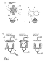
- FIG. 1 is a highly schematic example of an embodiment of the proposed heater for thermoforming shown.
- FIG. 1a shows the heating station or heating device and
- FIG. 1b the forming station, which connects to the heating station.
- the forming station is shown in three working cycles. In this case, the essential part of the invention is implemented in the heating station.
- the presentation of the forming station is to illustrate the forming process without the use of pre-stretching dies.
- a mold 3 with channels 4 in the bottom area which are connected to a vacuum pump 5b, and a mold top, which is connected to a compressed air supply 5a, is shown.
- the semifinished product 1 to be formed in this example a thin sheet of a thermoplastic, is positioned in the heating station, as in FIG FIG. 1a is shown.
- the heating plates or Kunststoffproof wornen 2 are brought simultaneously from both sides in contact with the semifinished product 1.
- the heating plates 2 are designed so that they bring a lower heating power in the areas of the semifinished product 1, which rest later at the lower corners of the mold 3. In these areas, therefore, a lower material flow achieved during the forming, so that there targeted a greater wall thickness is achieved.
- Each of the heating plates 2 in this case has only a single heating circuit of a ceramic heating layer, which is designed in the layout so that the desired local temperature distribution in the semifinished product 1 is achieved.
- the ceramic heating layer forming the heating circuit 6 can be seen on the thermally insulating carrier 7.
- the right part of the FIG. 1a shows a detail of a top view of the heating plate. 2
- the semifinished product 1 After heating of the semifinished product by thermal contact with the heating plates 2, the semifinished product 1 is positioned in the forming station. A vacuum is generated in the cavity of the mold 3 located below the semifinished product 1 via the vacuum pump 5b, through which the semifinished product 1 is sucked onto the inner wall of the mold 3 (cf. Fig. 1b ). At the same time, an overpressure is applied above the semifinished product 1 via the compressed air supply 5a, which assists the deformation. After this process, the semifinished product 1 is cooled in this form while maintaining the suction effect and the overpressure, so that the cooling takes place under forced form. After cooling, the finished molded part can be removed from the mold 3.
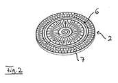
- the locally different heating of the semifinished product by means of thermal contact heating is achieved by a suitable uneven distribution of the respective heating circuit over the surface of the heating plate.
- Fig. 2 shows an example of a heating plate 2, on which a single ceramic heating circuit 6 is applied to the ceramic support 7.
- the heating circuit 6 generates due to the distribution on the surface of the carrier 7 in different areas different temperatures.
- the desired temperature distribution can be achieved at any time. If a different temperature distribution is desired, another heating plate 2 with a different geometric distribution of the heating lines of the heating circuit 6 is used.
Description
Die vorliegende Erfindung betrifft ein Verfahren zum Thermoformen von thermoplastischen Halbzeugen bei dem die Halbzeuge bis zur Umformtemperatur erwärmt, durch das Anlegen eines Differenzdrucks zwischen Halbzeugoberseite und Halbzeugunterseite zu einem dreidimensionalen Formteil geformt und anschließend unter Formzwang abgekühlt werden, wobei durch lokal unterschiedliche Erwärmung des Halbzeugs vor der Formung ein lokal unterschiedliches Umformverhalten erreicht wird. Die Erfindung betrifft auch eine Heizeinrichtung zur Durchführung des Verfahrens.The present invention relates to a method for thermoforming thermoplastic semi-finished products in which the semi-finished products heated to the forming temperature, formed by the application of a differential pressure between the semifinished product top and semifinished product bottom to a three-dimensional molded part and then cooled under forced deformation, wherein by locally different heating of the semifinished product before the Forming a locally different forming behavior is achieved. The invention also relates to a heating device for carrying out the method.
Beim Thermoformen wird ein thermoplastisches Halbzeug in eine definierte dreidimensionale Form gebracht. Für die Formung ist es erforderlich, das Halbzeug mindestens bis auf die Umformtemperatur zu erhitzen, bei der das Material ein für die Formung geeignetes Verhalten aufweist. Der Umformvorgang selbst wird durch eine Druckdifferenz zwischen Halbzeugoberseite und Halbzeugunterseite und je nach Umformgrad auch durch zusätzliches mechanisches Vorstrecken realisiert. Die Druckdifferenz wird durch den Einsatz von Druckluft und/oder Vakuum erzeugt. Nach der Formung erfolgt die Abkühlung des Halbzeugs. Als Halbzeuge kommen zumeist Kunststofffolien oder Kunststoffplatten zum Einsatz.In thermoforming, a thermoplastic semi-finished product is brought into a defined three-dimensional shape. For the molding, it is necessary to heat the semi-finished product at least up to the forming temperature, at which the material has a behavior suitable for shaping. The forming process itself is realized by a pressure difference between the top of the semifinished product and the bottom of the semifinished product and, depending on the degree of deformation, also by additional mechanical pre-stretching. The pressure difference is generated by the use of compressed air and / or vacuum. After shaping, the cooling of the semifinished product takes place. As semi-finished plastic films or plastic plates are mostly used.
Beim Prozess der Formung ist es bei einigen dreidimensionalen Formen erforderlich, ein lokal unterschiedliches Umformverhalten oder eine bestimmte Wanddickenverteilung im Formteil zu erreichen, um beispielsweise einer unerwünschten Verdünnung an Ecken oder Kanten des herzustellenden Formteils entgegenzuwirken. Ziel ist es, dadurch die gewünschte Stabilität und Integrität des Formteils sicherzustellen. Je nach Temperatur verändern sich die Materialeigenschaften des thermoplastischen Materials und damit auch das Umformverhalten. Durch ein ungleichmäßiges Temperaturfeld kann bei der Aufheizung gezielt ein ungleichmäßiges Umformverhalten aufgeprägt werden, über das die Materialverteilung am herzustellenden Formteil steuerbar ist.In the process of forming, it is necessary for some three-dimensional shapes, to achieve a locally different forming behavior or a certain wall thickness distribution in the molding, for example, to counteract undesirable dilution at corners or edges of the molded part. The aim is to ensure the desired stability and integrity of the molded part. Depending on the temperature, the material properties of the thermoplastic material and thus also the forming behavior change. Due to an uneven temperature field, an uneven deformation behavior can be impressed during heating in a targeted manner, via which the material distribution on the molded part to be produced can be controlled.
Die Erwärmung oder Aufheizung des Halbzeugs erfolgt für kleinere Formen in der Regel durch Kontaktheizung. Diese Art der Aufheizung des Halbzeugs mittels direkten Wärmekontakts ermöglicht bisher aufgrund der Problematik der Wärmeleitung innerhalb des Heizwerkzeugs insbesondere bei kleinen Umformgeometrien keine gezielte und steuerbare ungleichmäßige Beheizung, um dadurch ein lokal unterschiedliches Umformverhalten zu erreichen. Um die Wanddickenverteilung am herzustellenden Formteil zu beeinflussen, werden daher überwiegend Vorstreckstempel eingesetzt. Mit diesen Stempeln kann durch den direkten Kontakt des erwärmten Halbzeugs mit dem Stempel eine definierte lokale Abkühlung in den nicht zu stark zu verformenden Bereichen erreicht werden. Weiterhin wird durch die Stempelbewegung ein Vorstrecken des Halbzeugs bewirkt, welches die Wanddickenverteilung maßgeblich beeinflusst. Durch Anlegen eines Differenzdrucks, d.h. Überdruck, Unterdruck oder beides, erfolgt dann die endgültige Ausformung.The heating or heating of the semifinished product is for smaller forms usually by contact heating. This type of heating of the semifinished product by means of direct thermal contact previously made possible due to the problem of heat conduction within the heating tool, especially for small Umformgeometrien no targeted and controllable non-uniform heating, thereby achieving a locally different forming behavior. In order to influence the wall thickness distribution on the molded part to be produced, therefore, preforming dies are predominantly used. With these punches can be achieved by the direct contact of the heated semi-finished product with the stamp a defined local cooling in the not too strong parts to be deformed. Furthermore, a pre-stretching of the semifinished product is effected by the punch movement, which significantly influences the wall thickness distribution. By applying a differential pressure, ie overpressure, negative pressure or both, then takes the final shape.
Aus der
In
In
Die
Die
Die Aufgabe der vorliegenden Erfindung besteht darin, ein Verfahren und eine Heizeinrichtung zum Thermoformen anzugeben, mit denen ein lokal unterschiedliches Umformverhalten im Halbzeug ohne Vorstreckstempel auch für kleinere und mittelgroße Umformgeometrien mit einer fein einstellbaren Temperaturverteilung innerhalb des Halbzeugs erreicht werden kann und die keine Abstimmung auf Absorptionseigenschaften des Halbzeugs erfordern.The object of the present invention is to specify a method and a heating device for thermoforming, with which a locally different forming behavior in the semifinished product without pre-stretching punch also for smaller and medium-sized forming geometries with a finely adjustable temperature distribution within the semifinished product achieved can be and do not require a vote on absorption properties of the semifinished product.
Die Aufgabe wird mit dem Verfahren und der Heizeinrichtung gemäß den Patentansprüchen 1 und 4 gelöst. Vorteilhafte Ausgestaltungen des Verfahrens sowie der Heizeinrichtung sind Gegenstand der abhängigen Patentansprüche oder lassen sich der nachfolgenden Beschreibung und den Ausführungsbeispielen entnehmen.The object is achieved with the method and the heating device according to
Beim vorgeschlagenen Verfahren zum Thermoformen von thermoplastischen Halbzeugen werden die Halbzeuge bis auf die Umformtemperatur erwärmt, durch einen angelegten Differenzdruck zwischen Halbzeugober- und - unterseite zu einem dreidimensionalen Formteil geformt und anschließend unter Formzwang abgekühlt, wobei durch lokal unterschiedliche Erwärmung des Halbzeugs vor und/oder während der Formung ein lokal unterschiedliches Umformverhalten erreicht wird. Unter der Umformtemperatur wird hierbei der Temperaturbereich verstanden, in dem sich das Material umformen lässt. Beim Thermoformen liegt die Umformtemperatur unter der Fließtemperatur des Kunststoffs, wobei der Kunststoff noch relativ formstabil ist, jedoch schon durch kleine Krafteinwirkungen plastisch verformt werden kann. Die Umformung selbst kann dabei mit bekannten Techniken erfolgen, insbesondere durch Vakuum-Formen oder Druckluft-Formen oder durch eine Kombination beider Techniken. Die gleichen Techniken können auch zur Sicherstellung des Formzwangs während der Abkühlungsphase dienen. Das vorgeschlagene Verfahren zeichnet sich dadurch aus, dass die Erwärmung des Formteils durch Wärmekontaktheizung erfolgt, bei der zwei Kontaktheizeinrichtungen eingesetzt werden, die von gegenüberliegenden Seiten gleichzeitig mit dem Halbzeug in Kontakt gebracht werden. Jede Kontaktheizeinrichtung umfasst dabei einen einzigen flächigen Heizkreis aus einer keramischen Heizschicht auf einem thermisch isolierenden Träger. Die Heizkreise sind so auf der Fläche des Trägers ausgebildet, dass sie über diese Fläche lokal unterschiedliche Heizleistung abgeben. Dies wird durch die geometrische Ausgestaltung und/oder Verteilung des jeweiligen Heizkreises auf dieser Fläche erreicht. Als Träger kann beispielsweise eine keramische Platte eingesetzt werden.In the proposed method for thermoforming of thermoplastic semi-finished products, the semi-finished products are heated to the forming temperature, formed by an applied differential pressure between Halbzeugober- and - bottom to form a three-dimensional molded part and then cooled under forced deformation, wherein by locally different heating of the semifinished before and / or during the shaping a locally different forming behavior is achieved. In this case, the forming temperature is understood to be the temperature range in which the material can be formed. When thermoforming the forming temperature is below the flow temperature of the plastic, wherein the plastic is still relatively dimensionally stable, but can be plastically deformed even by small forces. The deformation itself can be done with known techniques, in particular by vacuum molding or compressed air molding or by a combination of both techniques. The same techniques can also be used to ensure mold compaction during the cooling phase serve. The proposed method is characterized in that the heating of the molded part takes place by thermal contact heating, in which two contact heating devices are used, which are brought into contact with the semifinished product from opposite sides simultaneously. Each contact heater comprises a single planar heating circuit of a ceramic heating layer on a thermally insulating support. The heating circuits are formed on the surface of the carrier so that they deliver locally different heating power over this area. This is achieved by the geometric design and / or distribution of the respective heating circuit on this surface. As a carrier, for example, a ceramic plate can be used.
Die zur Durchführung des Verfahrens ausgebildete Heizeinrichtung zur Erwärmung eines eingebrachten Halbzeugs bis zur Umformtemperatur, an die sich beim Thermoformen eine Formstation zur Umformung des erwärmten Halbzeugs zu einem dreidimensionalen Formteil anschließt, ist durch zwei Kontaktheizeinrichtungen gebildet, die von gegenüberliegenden Seiten gleichzeitig mit dem Halbzeug in Kontakt bringbar sind. Jede Kontaktheizeinrichtung umfasst einen einzigen Heizkreis aus einer keramischen Heizschicht auf einem thermisch isolierenden Träger. Die Heizkreise sind dabei so auf der Fläche des Trägers ausgebildet, dass sie über diese Fläche lokal unterschiedliche Heizleistung abgeben.The heating device designed for carrying out the method for heating an introduced semifinished product up to the forming temperature, which is followed by a forming station for forming the heated semifinished product into a three-dimensional molded part during thermoforming, is formed by two contact heating devices which simultaneously come into contact with the semifinished product from opposite sides can be brought. Each contact heater comprises a single heating circuit of a ceramic heating layer on a thermally insulating support. The heating circuits are designed on the surface of the carrier so that they deliver locally different heating power over this area.
Durch den Einsatz von Kontaktheizeinrichtungen mit jeweils einem einzelnen flächigen Heizkreis, der aus einer keramischen Heizschicht gebildet und auf einem thermisch isolierenden Träger aufgebracht ist, wird zum einen eine unerwünschte Wärmeleitung während der Aufheizphase über den Träger weitgehend vermieden. Dies ermöglicht zum anderen eine gezielte Steuerung der Temperaturverteilung bei der Aufheizung durch eine gezielte ungleichmäßige Verteilung bzw. geometrische Ausgestaltung des Heizkreises auf der dafür vorgesehenen Fläche des Trägers. Durch die nahezu freie Gestaltbarkeit der die Heizkreise bildenden keramischen Heizschichten und somit der Heizleistung auf dieser Fläche (Heizbild) kann der Wärmeeintrag in das jeweilige Halbzeug gezielt vorgegeben werden. Die Heizschichten werden dabei besonders vorteilhaft in der geometrischen Form der gewünschten Heizkreise als dünne Schicht aufgedruckt. Infolge des vergleichsweise geringen Querschnitts der Heizkeramik und der thermischen Entkopplung der Heizschichten vom Träger ist eine hochdynamische Temperaturregelung möglich. Über die Gestaltung des Heizkreis-Layouts wird die gewünschte ungleichmäßige Temperaturverteilung erreicht.Through the use of Kontaktheizeinrichtungen each having a single planar heating circuit, which consists of a ceramic heating layer and on a thermally insulating support is applied, on the one hand undesirable heat conduction during the heating phase over the carrier is largely avoided. On the other hand, this allows targeted control of the temperature distribution during heating by means of a targeted uneven distribution or geometric configuration of the heating circuit on the surface of the carrier provided for this purpose. Due to the almost free configurability of the heating circuits forming ceramic heating layers and thus the heat output on this surface (heating image), the heat input can be selectively specified in the respective semi-finished. The heating layers are printed particularly advantageous in the geometric shape of the desired heating circuits as a thin layer. Due to the comparatively small cross section of the ceramic heater and the thermal decoupling of the heating layers from the carrier, a highly dynamic temperature control is possible. The design of the heating circuit layout achieves the desired uneven temperature distribution.
Das vorgeschlagene Verfahren und die zugehörige Heizeinrichtung ermöglichen, durch partielle Aufheizung des thermoplastischen Materials des Halbzeugs die Wanddickenverteilung bei der Formung gezielt zu beeinflussen. Auf die Verwendung von Vorstreckstempeln kann hierbei vollständig verzichtet werden. Die Wanddickenverteilung wird hauptsächlich durch die Temperaturverteilung über die Heizbereiche gesteuert. Weiterhin kann die energetische Effizienz des Aufheizvorgangs durch die gezielte Energieleitung verbessert werden Dies wird dadurch erreicht, dass die Heizung nur beim direkten Kontakt mit dem Halbzeug betrieben wird. Die Heizkreise sind so konzipiert, dass sie nur den Bereich, der umgeformt werden soll erhitzen. Weiterhin wird durch den Kontakt der Heizkreise mit dem Halbzeug die Wärme direkt übertragen. Im Vergleich zu einem mit Strahlungsheizung durchgeführten Thermoformen spielt das Absorptionsvermögen des thermoplastischen Halbzeugs keine Rolle. Beim vorgeschlagenen Verfahren muss lediglich beim Design der Heizkreise die Lage und Dimension der Heizleitungen bzw. Heizkreise so gewählt werden, dass die jeweilige Heizleistung an den gewünschten Positionen erzielt werden kann. Dies kann vorab rechnerisch simuliert werden. Der Gestaltungsvielfalt sind hierbei lediglich physikalische Grenzen gesetzt. Durch den geringen Querschnitt der Heizleitungen und die thermische Entkopplung vom Träger besitzen die Heizleitungen eine geringe Wärmekapazität. Es ist somit eine hocheffiziente und hochdynamische Temperaturführung beim Aufheizen des Halbzeugs möglich.The proposed method and the associated heating device make it possible to influence the wall thickness distribution during shaping by partial heating of the thermoplastic material of the semifinished product. In this case, the use of pre-stretching dies can be completely dispensed with. The wall thickness distribution is mainly controlled by the temperature distribution over the heating areas. Furthermore, the energy efficiency of the heating process can be improved by the targeted power line This is achieved in that the heater is operated only in direct contact with the semifinished product. The Heating circuits are designed to heat only the area that needs to be reshaped. Furthermore, the heat is transferred directly by the contact of the heating circuits with the semi-finished product. In comparison with a thermoforming carried out with radiant heating, the absorption capacity of the thermoplastic semifinished product plays no role. In the proposed method, the position and dimension of the heating cables or heating circuits need only be selected in the design of the heating circuits so that the respective heating power can be achieved at the desired positions. This can be simulated in advance by calculation. The design variety here are only physical limits set. Due to the small cross-section of the heating cables and the thermal decoupling from the carrier, the heating cables have a low heat capacity. It is thus a highly efficient and highly dynamic temperature control when heating the semifinished product possible.
In einer vorteilhaften Ausgestaltung wird der temperaturabhängige Widerstand der Heizkreise zur Temperaturerfassung und -regelung eingesetzt. Durch diese Nutzung der Temperaturabhängigkeit des elektrischen Widerstands des Heizkreises als Messgröße für die Halbzeugtemperatur kann auf den Einsatz von Temperaturfühlern für die Steuerung verzichtet werden. Damit kann der Wärmeenergieeintrag über die Steuerung direkt erfasst und gesteuert oder zur Einhaltung einer lokalen Solltemperatur geregelt werden. Dies erfolgt über eine entsprechend ausgestaltete Steuereinrichtung, die den Widerstand des Heizkreises misst (Messung von Strom I und Spannung U) und den jeweiligen Heizkreis auf Basis dieser Messung zur Abgabe der für das Erreichen oder die Aufrechterhaltung einer bestimmten Temperatur des Halbzeugs erforderlichen Heizleistung ansteuert. Die Heizeinrichtung lässt sich bei dem Verfahren auch als Impulsheizung betreiben.In an advantageous embodiment of the temperature-dependent resistance of the heating circuits for temperature detection and control is used. Through this use of the temperature dependence of the electrical resistance of the heating circuit as a measure of the semifinished temperature can be dispensed with the use of temperature sensors for the control. Thus, the heat energy input can be detected and controlled directly via the controller or regulated to comply with a local setpoint temperature. This is done via a correspondingly designed control device that measures the resistance of the heating circuit (measurement of current I and voltage U) and the respective heating circuit on the basis of this measurement to deliver the for the Reaching or maintaining the maintenance of a certain temperature of the semifinished product required heating power. The heater can be operated in the process as a pulse heating.
Der thermisch isolierende Träger kann beim vorliegenden Verfahren bzw. der vorliegenden Heizeinrichtung beispielsweise aus Keramiken (z.B. Al2O3, AlN, Si3N4), Quarz oder Glaskeramiken bestehen. Für die keramischen Heizschichten können als Materialien bspw. Mo-Silizide oder RuO2 eingesetzt werden. Die Dicke dieser Heizschichten kann bspw. im Bereich zwischen 2 und 100 µm liegen. Die Heizschichten können hierbei direkt oder über eine bspw. keramische Zwischenschicht auf dem Träger aufgebracht sein.The thermally insulating support may in the present method or the present heater, for example, ceramics (eg Al 2 O 3 , AlN, Si 3 N 4 ), quartz or glass ceramics exist. For the ceramic heating layers can be used as materials, for example. Mo silicides or RuO 2 . The thickness of these heating layers can, for example, be in the range between 2 and 100 μm. The heating layers can be applied directly or via an example. Ceramic intermediate layer on the support.
Der Einsatz aufdruckbarer bzw. aufgedruckter keramischer Heizschichten bietet zwar besondere Vorteile bei der Herstellung, allerdings lassen sich unter Verzicht auf diese Vorteile selbstverständlich auch andere Techniken zum Aufbringen der Heizkreise einsetzen.Although the use of printable or printed ceramic heating layers offers particular advantages in the production, but of course can be dispensed with these advantages, other techniques for applying the heating circuits.
Das vorgeschlagene Verfahren und die zugehörige Heizeinrichtung werden nachfolgend anhand von Ausführungsbeispielen in Verbindung mit den Zeichnungen nochmals kurz erläutert. Hierbei zeigen:
- Fig. 1
- in schematischer Darstellung ein Beispiel für eine Heizeinrichtung und daran anschließende Formstationen zum Thermoformen; und
- Fig. 2
- ein Beispiel für eine Ausgestaltung der Kontaktheizeinrichtungen.
- Fig. 1
- a schematic representation of an example of a heater and it subsequent forming stations for thermoforming; and
- Fig. 2
- an example of an embodiment of Kontaktheizeinrichtungen.
In
Das umzuformende Halbzeug 1, in diesem Beispiel eine dünne Platte aus einem thermoplastischen Kunststoff, wird in der Heizstation positioniert, wie in der
Nach der Aufheizung des Halbzeugs durch Wärmekontakt mit den Heizplatten 2 wird das Halbzeug 1 in der Formstation positioniert. Über die Vakuumpumpe 5b wird ein Unterdruck in dem unterhalb des Halbzeugs 1 befindlichen Hohlraum der Form 3 erzeugt, durch den das Halbzeug 1 an die Innenwandung der Form 3 angesaugt wird (vgl.
Bei dem vorgeschlagenen Verfahren wird die lokal unterschiedliche Aufheizung des Halbzeugs mittels Wärmekontaktheizung durch eine geeignete ungleichmäßige Verteilung des jeweiligen Heizkreises über der Fläche der Heizplatte erreicht.In the proposed method, the locally different heating of the semifinished product by means of thermal contact heating is achieved by a suitable uneven distribution of the respective heating circuit over the surface of the heating plate.
- 11
- HalbzeugWorkpiece
- 22
- Heizplatteheating plate
- 33
- Formshape
- 44
- Kanalchannel
- 5a5a
- DruckluftversorgungAir Supply
- 5b5b
- Vakuumpumpevacuum pump
- 66
- Heizkreisheating circuit
- 77
- Trägercarrier
Claims (6)
- A method for thermoforming thermoplastic semifinished products, in which the semifinished products (1) are heated to the forming temperature, formed into a three-dimensional formed part by means of an applied differential pressure between an upper side of the semifinished product and a lower side of the semifinished product and subsequently cooled with mould constraint,
wherein a locally different forming behavior is achieved due to locally different heating of the semifinished product (1) prior to the forming process, and
wherein the semifinished product (1) is heated by means of two contact heating devices (2) that can be simultaneously brought in contact with the semifinished product from opposite sides,
characterized in that each contact heating device comprises an individual heating circuit (6) consisting of a ceramic heating layer on a thermally insulating substrate (7), and in that the locally different heating is achieved due to a locally different geometric design of the heating circuits (6) on the substrate (7). - The method according to Claim 1,
characterized in
that an electric resistance of the heating circuits (6) is measured during the heating process and used for determining and controlling a temperature on the semifinished product (1). - The method according to Claim 1 or 2,
characterized in
that the heating circuits (6) are operated in a pulsed fashion. - A heating apparatus for carrying out the method according to one of Claims 1 to 3, wherein said heating apparatus is formed by two contact heating devices (2) that can be simultaneously brought in contact with the semifinished product from opposite sides,
characterized in that each contact heating device comprises an individual heating circuit (6) consisting of a ceramic heating layer on a thermally insulating substrate (7), and in that the heating circuits (6) are realized on a surface of the substrate (7) in such a way that they have a locally different heating power over this surface. - The heating apparatus according to Claim 4,
characterized in
that the heating circuits (6) are printed on the substrate (7). - The heating apparatus according to Claim 4 or 5,
characterized in
that the heating apparatus comprises a control unit with an automatic control that is designed for determining a temperature on the semifinished product (1) based on an electric resistance of one or both heating circuits (6) during the heating process, as well as for adjusting said temperature to a nominal temperature by activating the heating circuits.
Applications Claiming Priority (3)
| Application Number | Priority Date | Filing Date | Title |
|---|---|---|---|
| DE102008025832 | 2008-05-29 | ||
| DE102008062199A DE102008062199A1 (en) | 2008-05-29 | 2008-12-13 | Method and heater for thermoforming |
| PCT/DE2009/000708 WO2009143810A1 (en) | 2008-05-29 | 2009-05-20 | Method and heating device for thermoforming |
Publications (2)
| Publication Number | Publication Date |
|---|---|
| EP2293909A1 EP2293909A1 (en) | 2011-03-16 |
| EP2293909B1 true EP2293909B1 (en) | 2015-04-15 |
Family
ID=41254108
Family Applications (1)
| Application Number | Title | Priority Date | Filing Date |
|---|---|---|---|
| EP09753526.4A Not-in-force EP2293909B1 (en) | 2008-05-29 | 2009-05-20 | Method and heating device for thermoforming |
Country Status (5)
| Country | Link |
|---|---|
| US (1) | US20110101556A1 (en) |
| EP (1) | EP2293909B1 (en) |
| JP (1) | JP2011520672A (en) |
| DE (1) | DE102008062199A1 (en) |
| WO (1) | WO2009143810A1 (en) |
Cited By (1)
| Publication number | Priority date | Publication date | Assignee | Title |
|---|---|---|---|---|
| EP3515693B1 (en) | 2016-09-21 | 2020-07-01 | watttron GmbH | Sealing body |
Families Citing this family (11)
| Publication number | Priority date | Publication date | Assignee | Title |
|---|---|---|---|---|
| JP5727608B2 (en) * | 2010-08-02 | 2015-06-03 | サロング ソシエタ ペル アツィオニ | Molding equipment |
| DE102014202302B4 (en) * | 2013-07-03 | 2015-02-19 | Technische Universität Dresden | Device for heating preforms |
| DE102013214592B4 (en) | 2013-07-25 | 2020-03-05 | Universität Stuttgart | Method and device for thermoforming plastic products |
| US11701298B2 (en) | 2016-10-26 | 2023-07-18 | Holographyx Inc. | Pharmaceutical packs comprising holographic lidding material, and method of making the same |
| US11052020B2 (en) | 2016-10-26 | 2021-07-06 | Holographyx Inc. | Pharmaceutical packs comprising holographic lidding material, and method of making the same |
| DE102017009700A1 (en) | 2017-10-18 | 2019-04-18 | Vereinigung zur Förderung des Instituts für Kunststoffverarbeitung in Industrie und Handwerk an der Rhein.-Westf. Technischen Hochschule Aachen e.V. | Method and system for producing thermoformed components by means of active, local cooling of the semifinished product |
| DE102018003359A1 (en) * | 2018-04-25 | 2019-10-31 | Bosch Sprang Bv | METHOD, DEVICE AND TOOL TOOL FOR THERMOFORMS OF A FLAT FILM AND AN EQUIPMENT FOR PRODUCING SEMI-FINISHED PRODUCTS AND PRODUCTS |
| DE102018127611A1 (en) * | 2018-11-06 | 2020-05-07 | Uwe Beier | Method and device for forming flat substrates |
| WO2020152652A1 (en) | 2019-01-25 | 2020-07-30 | National Research Council Of Canada | Articulated forming caul for composite blank vacuum forming |
| CN112721122B (en) * | 2020-12-31 | 2021-09-28 | 江苏亿豪塑业股份有限公司 | Polytetrafluoroethylene panel mould convenient to cooling |
| DE102021111198A1 (en) | 2021-04-30 | 2022-11-03 | Scheu-Dental Gmbh | heater and system |
Citations (1)
| Publication number | Priority date | Publication date | Assignee | Title |
|---|---|---|---|---|
| US6091054A (en) * | 1997-03-03 | 2000-07-18 | Abbott Laboratories | Heater plate and method for using same |
Family Cites Families (20)
| Publication number | Priority date | Publication date | Assignee | Title |
|---|---|---|---|---|
| US3386503A (en) * | 1966-02-24 | 1968-06-04 | Continental Can Co | Differential heating plate |
| LU66646A1 (en) * | 1972-12-13 | 1974-07-10 | ||
| DE2600582A1 (en) * | 1976-01-09 | 1977-07-14 | Kiefel Gmbh Paul | Two-step heating of thermoplastics film or sheet - by first contact heating to below shaping temp. and then by e.g. infrared radiation to shaping temp. |
| DE3481978D1 (en) * | 1983-10-06 | 1990-05-23 | Servichem Ag | DEVICE FOR PRODUCING OBJECTS FROM A MATERIAL COVER OF A THERMOPLASTIC FILM AND THE USE THEREOF FOR PRODUCING CONTAINER PARTS. |
| US4619806A (en) * | 1985-03-15 | 1986-10-28 | The Procter & Gamble Company | Method of forming highly oriented thermoplastic articles |
| FR2602174B1 (en) * | 1986-07-31 | 1988-11-18 | Erca Holding | METHOD AND DEVICE FOR ADJUSTING THE HEATING OF A THERMOPLASTIC BAND USED IN A THERMOFORMING STATION |
| US5571473A (en) * | 1989-12-28 | 1996-11-05 | Idemitsu Petrochemical Co., Ltd. | Process for thermoforming thermoplastic resin sheet |
| US5162124A (en) * | 1990-03-19 | 1992-11-10 | Illinois Tool Works Inc. | Die system for thermoforming thermoformable sheet material |
| US5290490A (en) * | 1990-06-29 | 1994-03-01 | General Electric Company | Method and apparatus for differentially heating and thermoforming a polymer sheet |
| DE4410204C2 (en) * | 1994-03-24 | 2002-10-24 | Tetra Laval Holdings & Finance | Hot plate for heating a section of thermoformable plastic |
| WO1998048995A1 (en) * | 1997-05-01 | 1998-11-05 | Jones William C | Pre-cut roll and thermoformer machine |
| WO1998051127A1 (en) * | 1997-05-06 | 1998-11-12 | Thermoceramix, L.L.C. | Deposited resistive coatings |
| IT1299648B1 (en) * | 1998-03-18 | 2000-03-24 | Isap Omv Group Spa | PROCESS AND PLANT FOR SELECTIVE HEATING BY ZONES OF A THERMOFORMABLE MATERIAL |
| US6835916B2 (en) * | 1999-08-09 | 2004-12-28 | Ibiden, Co., Ltd | Ceramic heater |
| US6519835B1 (en) * | 2000-08-18 | 2003-02-18 | Watlow Polymer Technologies | Method of formable thermoplastic laminate heated element assembly |
| US6878906B2 (en) * | 2000-08-30 | 2005-04-12 | Ibiden Co., Ltd. | Ceramic heater for semiconductor manufacturing and inspecting equipment |
| DE10349156B4 (en) | 2003-10-22 | 2009-05-20 | BLZ Bayerisches Laserzentrum Gemeinnützige Forschungsgesellschaft mbH | Method and apparatus for pneumatic thermoforming of plastic products |
| DE102005018652A1 (en) | 2005-04-21 | 2006-10-26 | Uhlmann Pac-Systeme Gmbh & Co. Kg | heater |
| KR101299495B1 (en) * | 2005-12-08 | 2013-08-29 | 신에쓰 가가꾸 고교 가부시끼가이샤 | Ceramics heater, heater power feeding component and method for manufacturing ceramics heater |
| DE102006045327A1 (en) | 2006-09-22 | 2008-04-03 | Cfs Germany Gmbh | Heating plate with a variety of heating cartridges |
-
2008
- 2008-12-13 DE DE102008062199A patent/DE102008062199A1/en not_active Withdrawn
-
2009
- 2009-05-20 EP EP09753526.4A patent/EP2293909B1/en not_active Not-in-force
- 2009-05-20 US US12/994,929 patent/US20110101556A1/en not_active Abandoned
- 2009-05-20 JP JP2011510822A patent/JP2011520672A/en active Pending
- 2009-05-20 WO PCT/DE2009/000708 patent/WO2009143810A1/en active Application Filing
Patent Citations (1)
| Publication number | Priority date | Publication date | Assignee | Title |
|---|---|---|---|---|
| US6091054A (en) * | 1997-03-03 | 2000-07-18 | Abbott Laboratories | Heater plate and method for using same |
Cited By (2)
| Publication number | Priority date | Publication date | Assignee | Title |
|---|---|---|---|---|
| EP3515693B1 (en) | 2016-09-21 | 2020-07-01 | watttron GmbH | Sealing body |
| US11667421B2 (en) | 2016-09-21 | 2023-06-06 | watttron GmbH | Sealing body |
Also Published As
| Publication number | Publication date |
|---|---|
| EP2293909A1 (en) | 2011-03-16 |
| DE102008062199A1 (en) | 2009-12-03 |
| US20110101556A1 (en) | 2011-05-05 |
| WO2009143810A1 (en) | 2009-12-03 |
| JP2011520672A (en) | 2011-07-21 |
Similar Documents
| Publication | Publication Date | Title |
|---|---|---|
| EP2293909B1 (en) | Method and heating device for thermoforming | |
| EP3725491B1 (en) | Device for heating preforms or preformed thermoplastic semi-finished products for use in blow moulding machines | |
| EP3369554B1 (en) | Method of forming blisters in a heated film web | |
| EP3804959B1 (en) | Deep-drawing device for deep-drawing packaging bodies, such as packaging trays madefrom deep-drawn film | |
| EP3717853B1 (en) | Tempering unit and tempering method for a furnace for the heat treatment of a plate | |
| DE102006045027B4 (en) | Apparatus and method for heating a thermoplastic film sheet or plastic sheet | |
| DE3135206C1 (en) | Process for regulating the temperature of the upper and lower part of tools for the production of containers from thermoplastic plastic film and tools for carrying out the process | |
| DE102012101704B4 (en) | Flexible mold | |
| EP1181143A1 (en) | Method for producing plastic parts having an impressed structure, and a device for carrying out said method | |
| WO2018069428A1 (en) | Molding tool | |
| DE102019110705B4 (en) | Pressing device and method for producing a pressed product | |
| EP1916090B1 (en) | Method for manufacturing plastic parts | |
| DE10203250C1 (en) | Micro-structuring of polymer films used as substrates in opto-electronics, preheats film to below glass point, then presses it using structured molding plate between hot rollers | |
| DE19521359A1 (en) | Punching tool for plastic films has a heated steel band knife | |
| DE202014105080U1 (en) | Press plate | |
| WO2019206448A1 (en) | Method, device and mould for thermoforming a flat film and installation for producing semifinished products and products | |
| DE102020127719B3 (en) | Pressing device and method for producing a pressed product | |
| EP4212339A1 (en) | Device for laminating a plurality of layers arranged in a stack to form a laminate composite | |
| EP3577081A1 (en) | Method and device for producing a thin-walled object with a three-dimensional form | |
| EP3778056B1 (en) | Method for thermoforming aluminium sheets by means of stretch forming | |
| DE1604596A1 (en) | Press forming of objects | |
| EP4353450A1 (en) | Additive manufacturing apparatus | |
| DE102015016961A1 (en) | Method and device for heating sheets and motor vehicle | |
| DE102015226532B4 (en) | Method and device for stretching and / or shaping semi-finished products made of thermoplastic material | |
| DE102018106509A1 (en) | Method and device for producing a conveyor belt with embedded flat coils |
Legal Events
| Date | Code | Title | Description |
|---|---|---|---|
| PUAI | Public reference made under article 153(3) epc to a published international application that has entered the european phase |
Free format text: ORIGINAL CODE: 0009012 |
|
| 17P | Request for examination filed |
Effective date: 20101215 |
|
| AK | Designated contracting states |
Kind code of ref document: A1 Designated state(s): AT BE BG CH CY CZ DE DK EE ES FI FR GB GR HR HU IE IS IT LI LT LU LV MC MK MT NL NO PL PT RO SE SI SK TR |
|
| AX | Request for extension of the european patent |
Extension state: AL BA RS |
|
| RIN1 | Information on inventor provided before grant (corrected) |
Inventor name: HANKE, TILO Inventor name: BACH, SASCHA |
|
| DAX | Request for extension of the european patent (deleted) | ||
| RIC1 | Information provided on ipc code assigned before grant |
Ipc: B29C 51/42 20060101ALN20141013BHEP Ipc: B29C 35/02 20060101ALI20141013BHEP Ipc: B29C 51/10 20060101ALI20141013BHEP Ipc: B29B 13/02 20060101AFI20141013BHEP Ipc: H05B 3/26 20060101ALI20141013BHEP Ipc: B29C 51/46 20060101ALI20141013BHEP |
|
| GRAP | Despatch of communication of intention to grant a patent |
Free format text: ORIGINAL CODE: EPIDOSNIGR1 |
|
| RIC1 | Information provided on ipc code assigned before grant |
Ipc: B29C 51/46 20060101ALN20141114BHEP Ipc: B29B 13/02 20060101AFI20141114BHEP Ipc: B29C 51/42 20060101ALN20141114BHEP Ipc: H05B 3/26 20060101ALI20141114BHEP Ipc: B29C 35/02 20060101ALI20141114BHEP Ipc: B29C 51/10 20060101ALN20141114BHEP |
|
| INTG | Intention to grant announced |
Effective date: 20141205 |
|
| RIC1 | Information provided on ipc code assigned before grant |
Ipc: B29C 51/42 20060101ALN20141127BHEP Ipc: B29B 13/02 20060101AFI20141127BHEP Ipc: H05B 3/26 20060101ALI20141127BHEP Ipc: B29C 51/10 20060101ALN20141127BHEP Ipc: B29C 51/46 20060101ALN20141127BHEP Ipc: B29C 35/02 20060101ALI20141127BHEP |
|
| GRAS | Grant fee paid |
Free format text: ORIGINAL CODE: EPIDOSNIGR3 |
|
| GRAA | (expected) grant |
Free format text: ORIGINAL CODE: 0009210 |
|
| AK | Designated contracting states |
Kind code of ref document: B1 Designated state(s): AT BE BG CH CY CZ DE DK EE ES FI FR GB GR HR HU IE IS IT LI LT LU LV MC MK MT NL NO PL PT RO SE SI SK TR |
|
| REG | Reference to a national code |
Ref country code: GB Ref legal event code: FG4D Free format text: NOT ENGLISH Ref country code: CH Ref legal event code: EP |
|
| REG | Reference to a national code |
Ref country code: IE Ref legal event code: FG4D Free format text: LANGUAGE OF EP DOCUMENT: GERMAN |
|
| REG | Reference to a national code |
Ref country code: AT Ref legal event code: REF Ref document number: 721686 Country of ref document: AT Kind code of ref document: T Effective date: 20150515 |
|
| REG | Reference to a national code |
Ref country code: DE Ref legal event code: R096 Ref document number: 502009010917 Country of ref document: DE Effective date: 20150521 |
|
| REG | Reference to a national code |
Ref country code: CH Ref legal event code: NV Representative=s name: WEINMANN ZIMMERLI, CH |
|
| REG | Reference to a national code |
Ref country code: FR Ref legal event code: PLFP Year of fee payment: 7 |
|
| REG | Reference to a national code |
Ref country code: NL Ref legal event code: VDEP Effective date: 20150415 |
|
| REG | Reference to a national code |
Ref country code: LT Ref legal event code: MG4D |
|
| PG25 | Lapsed in a contracting state [announced via postgrant information from national office to epo] |
Ref country code: NL Free format text: LAPSE BECAUSE OF FAILURE TO SUBMIT A TRANSLATION OF THE DESCRIPTION OR TO PAY THE FEE WITHIN THE PRESCRIBED TIME-LIMIT Effective date: 20150415 |
|
| PG25 | Lapsed in a contracting state [announced via postgrant information from national office to epo] |
Ref country code: ES Free format text: LAPSE BECAUSE OF FAILURE TO SUBMIT A TRANSLATION OF THE DESCRIPTION OR TO PAY THE FEE WITHIN THE PRESCRIBED TIME-LIMIT Effective date: 20150415 Ref country code: LT Free format text: LAPSE BECAUSE OF FAILURE TO SUBMIT A TRANSLATION OF THE DESCRIPTION OR TO PAY THE FEE WITHIN THE PRESCRIBED TIME-LIMIT Effective date: 20150415 Ref country code: FI Free format text: LAPSE BECAUSE OF FAILURE TO SUBMIT A TRANSLATION OF THE DESCRIPTION OR TO PAY THE FEE WITHIN THE PRESCRIBED TIME-LIMIT Effective date: 20150415 Ref country code: NO Free format text: LAPSE BECAUSE OF FAILURE TO SUBMIT A TRANSLATION OF THE DESCRIPTION OR TO PAY THE FEE WITHIN THE PRESCRIBED TIME-LIMIT Effective date: 20150715 Ref country code: HR Free format text: LAPSE BECAUSE OF FAILURE TO SUBMIT A TRANSLATION OF THE DESCRIPTION OR TO PAY THE FEE WITHIN THE PRESCRIBED TIME-LIMIT Effective date: 20150415 Ref country code: PT Free format text: LAPSE BECAUSE OF FAILURE TO SUBMIT A TRANSLATION OF THE DESCRIPTION OR TO PAY THE FEE WITHIN THE PRESCRIBED TIME-LIMIT Effective date: 20150817 |
|
| PG25 | Lapsed in a contracting state [announced via postgrant information from national office to epo] |
Ref country code: GR Free format text: LAPSE BECAUSE OF FAILURE TO SUBMIT A TRANSLATION OF THE DESCRIPTION OR TO PAY THE FEE WITHIN THE PRESCRIBED TIME-LIMIT Effective date: 20150716 Ref country code: LV Free format text: LAPSE BECAUSE OF FAILURE TO SUBMIT A TRANSLATION OF THE DESCRIPTION OR TO PAY THE FEE WITHIN THE PRESCRIBED TIME-LIMIT Effective date: 20150415 Ref country code: IS Free format text: LAPSE BECAUSE OF FAILURE TO SUBMIT A TRANSLATION OF THE DESCRIPTION OR TO PAY THE FEE WITHIN THE PRESCRIBED TIME-LIMIT Effective date: 20150815 |
|
| REG | Reference to a national code |
Ref country code: DE Ref legal event code: R097 Ref document number: 502009010917 Country of ref document: DE |
|
| PG25 | Lapsed in a contracting state [announced via postgrant information from national office to epo] |
Ref country code: EE Free format text: LAPSE BECAUSE OF FAILURE TO SUBMIT A TRANSLATION OF THE DESCRIPTION OR TO PAY THE FEE WITHIN THE PRESCRIBED TIME-LIMIT Effective date: 20150415 Ref country code: DK Free format text: LAPSE BECAUSE OF FAILURE TO SUBMIT A TRANSLATION OF THE DESCRIPTION OR TO PAY THE FEE WITHIN THE PRESCRIBED TIME-LIMIT Effective date: 20150415 Ref country code: MC Free format text: LAPSE BECAUSE OF FAILURE TO SUBMIT A TRANSLATION OF THE DESCRIPTION OR TO PAY THE FEE WITHIN THE PRESCRIBED TIME-LIMIT Effective date: 20150415 |
|
| PLBE | No opposition filed within time limit |
Free format text: ORIGINAL CODE: 0009261 |
|
| STAA | Information on the status of an ep patent application or granted ep patent |
Free format text: STATUS: NO OPPOSITION FILED WITHIN TIME LIMIT |
|
| REG | Reference to a national code |
Ref country code: IE Ref legal event code: MM4A |
|
| PG25 | Lapsed in a contracting state [announced via postgrant information from national office to epo] |
Ref country code: CZ Free format text: LAPSE BECAUSE OF FAILURE TO SUBMIT A TRANSLATION OF THE DESCRIPTION OR TO PAY THE FEE WITHIN THE PRESCRIBED TIME-LIMIT Effective date: 20150415 Ref country code: PL Free format text: LAPSE BECAUSE OF FAILURE TO SUBMIT A TRANSLATION OF THE DESCRIPTION OR TO PAY THE FEE WITHIN THE PRESCRIBED TIME-LIMIT Effective date: 20150415 Ref country code: SK Free format text: LAPSE BECAUSE OF FAILURE TO SUBMIT A TRANSLATION OF THE DESCRIPTION OR TO PAY THE FEE WITHIN THE PRESCRIBED TIME-LIMIT Effective date: 20150415 Ref country code: RO Free format text: LAPSE BECAUSE OF NON-PAYMENT OF DUE FEES Effective date: 20150415 |
|
| 26N | No opposition filed |
Effective date: 20160118 |
|
| PG25 | Lapsed in a contracting state [announced via postgrant information from national office to epo] |
Ref country code: IE Free format text: LAPSE BECAUSE OF NON-PAYMENT OF DUE FEES Effective date: 20150520 |
|
| REG | Reference to a national code |
Ref country code: FR Ref legal event code: PLFP Year of fee payment: 8 |
|
| PG25 | Lapsed in a contracting state [announced via postgrant information from national office to epo] |
Ref country code: SI Free format text: LAPSE BECAUSE OF FAILURE TO SUBMIT A TRANSLATION OF THE DESCRIPTION OR TO PAY THE FEE WITHIN THE PRESCRIBED TIME-LIMIT Effective date: 20150415 |
|
| PG25 | Lapsed in a contracting state [announced via postgrant information from national office to epo] |
Ref country code: MT Free format text: LAPSE BECAUSE OF FAILURE TO SUBMIT A TRANSLATION OF THE DESCRIPTION OR TO PAY THE FEE WITHIN THE PRESCRIBED TIME-LIMIT Effective date: 20150415 |
|
| REG | Reference to a national code |
Ref country code: FR Ref legal event code: PLFP Year of fee payment: 9 |
|
| PG25 | Lapsed in a contracting state [announced via postgrant information from national office to epo] |
Ref country code: BG Free format text: LAPSE BECAUSE OF FAILURE TO SUBMIT A TRANSLATION OF THE DESCRIPTION OR TO PAY THE FEE WITHIN THE PRESCRIBED TIME-LIMIT Effective date: 20150415 Ref country code: HU Free format text: LAPSE BECAUSE OF FAILURE TO SUBMIT A TRANSLATION OF THE DESCRIPTION OR TO PAY THE FEE WITHIN THE PRESCRIBED TIME-LIMIT; INVALID AB INITIO Effective date: 20090520 |
|
| PG25 | Lapsed in a contracting state [announced via postgrant information from national office to epo] |
Ref country code: CY Free format text: LAPSE BECAUSE OF FAILURE TO SUBMIT A TRANSLATION OF THE DESCRIPTION OR TO PAY THE FEE WITHIN THE PRESCRIBED TIME-LIMIT Effective date: 20150415 Ref country code: SE Free format text: LAPSE BECAUSE OF FAILURE TO SUBMIT A TRANSLATION OF THE DESCRIPTION OR TO PAY THE FEE WITHIN THE PRESCRIBED TIME-LIMIT Effective date: 20150415 |
|
| PG25 | Lapsed in a contracting state [announced via postgrant information from national office to epo] |
Ref country code: BE Free format text: LAPSE BECAUSE OF NON-PAYMENT OF DUE FEES Effective date: 20150531 |
|
| PG25 | Lapsed in a contracting state [announced via postgrant information from national office to epo] |
Ref country code: TR Free format text: LAPSE BECAUSE OF FAILURE TO SUBMIT A TRANSLATION OF THE DESCRIPTION OR TO PAY THE FEE WITHIN THE PRESCRIBED TIME-LIMIT Effective date: 20150415 |
|
| PG25 | Lapsed in a contracting state [announced via postgrant information from national office to epo] |
Ref country code: LU Free format text: LAPSE BECAUSE OF NON-PAYMENT OF DUE FEES Effective date: 20150520 |
|
| REG | Reference to a national code |
Ref country code: FR Ref legal event code: PLFP Year of fee payment: 10 |
|
| PG25 | Lapsed in a contracting state [announced via postgrant information from national office to epo] |
Ref country code: MK Free format text: LAPSE BECAUSE OF FAILURE TO SUBMIT A TRANSLATION OF THE DESCRIPTION OR TO PAY THE FEE WITHIN THE PRESCRIBED TIME-LIMIT Effective date: 20150415 |
|
| REG | Reference to a national code |
Ref country code: DE Ref legal event code: R082 Ref document number: 502009010917 Country of ref document: DE Representative=s name: GAGEL, ROLAND, DIPL.-PHYS.UNIV. DR.RER.NAT., DE Ref country code: DE Ref legal event code: R081 Ref document number: 502009010917 Country of ref document: DE Owner name: WATTTRON GMBH, DE Free format text: FORMER OWNER: FRAUNHOFER-GESELLSCHAFT ZUR FOERDERUNG DER ANGEWANDTEN FORSCHUNG E.V., 80686 MUENCHEN, DE |
|
| REG | Reference to a national code |
Ref country code: CH Ref legal event code: PK Free format text: BERICHTIGUNG INHABER Ref country code: CH Ref legal event code: PUE Owner name: WATTRON GMBH, DE Free format text: FORMER OWNER: FRAUNHOFER-GESELLSCHAFT ZUR FOERDERUNG DER ANGEWANDTEN FORSCHUNG, DE |
|
| REG | Reference to a national code |
Ref country code: GB Ref legal event code: 732E Free format text: REGISTERED BETWEEN 20181025 AND 20181102 |
|
| REG | Reference to a national code |
Ref country code: AT Ref legal event code: PC Ref document number: 721686 Country of ref document: AT Kind code of ref document: T Owner name: WATTTRON GMBH, DE Effective date: 20190110 |
|
| PGFP | Annual fee paid to national office [announced via postgrant information from national office to epo] |
Ref country code: DE Payment date: 20200525 Year of fee payment: 12 Ref country code: CH Payment date: 20200522 Year of fee payment: 12 Ref country code: FR Payment date: 20200519 Year of fee payment: 12 |
|
| PGFP | Annual fee paid to national office [announced via postgrant information from national office to epo] |
Ref country code: IT Payment date: 20200528 Year of fee payment: 12 Ref country code: GB Payment date: 20200522 Year of fee payment: 12 |
|
| PGFP | Annual fee paid to national office [announced via postgrant information from national office to epo] |
Ref country code: AT Payment date: 20200515 Year of fee payment: 12 |
|
| REG | Reference to a national code |
Ref country code: DE Ref legal event code: R119 Ref document number: 502009010917 Country of ref document: DE |
|
| REG | Reference to a national code |
Ref country code: CH Ref legal event code: PL |
|
| REG | Reference to a national code |
Ref country code: AT Ref legal event code: MM01 Ref document number: 721686 Country of ref document: AT Kind code of ref document: T Effective date: 20210520 |
|
| GBPC | Gb: european patent ceased through non-payment of renewal fee |
Effective date: 20210520 |
|
| PG25 | Lapsed in a contracting state [announced via postgrant information from national office to epo] |
Ref country code: CH Free format text: LAPSE BECAUSE OF NON-PAYMENT OF DUE FEES Effective date: 20210531 Ref country code: AT Free format text: LAPSE BECAUSE OF NON-PAYMENT OF DUE FEES Effective date: 20210520 Ref country code: LI Free format text: LAPSE BECAUSE OF NON-PAYMENT OF DUE FEES Effective date: 20210531 |
|
| PG25 | Lapsed in a contracting state [announced via postgrant information from national office to epo] |
Ref country code: GB Free format text: LAPSE BECAUSE OF NON-PAYMENT OF DUE FEES Effective date: 20210520 Ref country code: DE Free format text: LAPSE BECAUSE OF NON-PAYMENT OF DUE FEES Effective date: 20211201 |
|
| PG25 | Lapsed in a contracting state [announced via postgrant information from national office to epo] |
Ref country code: FR Free format text: LAPSE BECAUSE OF NON-PAYMENT OF DUE FEES Effective date: 20210531 |
|
| PG25 | Lapsed in a contracting state [announced via postgrant information from national office to epo] |
Ref country code: IT Free format text: LAPSE BECAUSE OF NON-PAYMENT OF DUE FEES Effective date: 20200520 |