EP4045255B1 - Moule, système de moule et procédé de fabrication des pièces en forme de particles mouseux - Google Patents
Moule, système de moule et procédé de fabrication des pièces en forme de particles mouseux Download PDFInfo
- Publication number
- EP4045255B1 EP4045255B1 EP20786292.1A EP20786292A EP4045255B1 EP 4045255 B1 EP4045255 B1 EP 4045255B1 EP 20786292 A EP20786292 A EP 20786292A EP 4045255 B1 EP4045255 B1 EP 4045255B1
- Authority
- EP
- European Patent Office
- Prior art keywords
- mold
- cavities
- trimming
- fluid
- cavity
- Prior art date
- Legal status (The legal status is an assumption and is not a legal conclusion. Google has not performed a legal analysis and makes no representation as to the accuracy of the status listed.)
- Active
Links
- 239000002245 particle Substances 0.000 title claims description 121
- 238000000034 method Methods 0.000 title claims description 36
- 230000008569 process Effects 0.000 title claims description 23
- 238000009966 trimming Methods 0.000 claims description 165
- 239000012530 fluid Substances 0.000 claims description 162
- 239000006260 foam Substances 0.000 claims description 119
- 239000003990 capacitor Substances 0.000 claims description 84
- 239000000463 material Substances 0.000 claims description 59
- 230000005672 electromagnetic field Effects 0.000 claims description 38
- 238000003466 welding Methods 0.000 claims description 24
- 238000005187 foaming Methods 0.000 claims description 14
- 239000007787 solid Substances 0.000 claims description 5
- 239000007788 liquid Substances 0.000 claims description 4
- 238000003825 pressing Methods 0.000 claims description 3
- 238000005496 tempering Methods 0.000 claims description 3
- 238000007599 discharging Methods 0.000 claims description 2
- 238000003780 insertion Methods 0.000 claims description 2
- 230000037431 insertion Effects 0.000 claims description 2
- 230000005684 electric field Effects 0.000 description 27
- 238000004088 simulation Methods 0.000 description 17
- 238000004519 manufacturing process Methods 0.000 description 16
- 238000012986 modification Methods 0.000 description 13
- 230000004048 modification Effects 0.000 description 13
- 230000000694 effects Effects 0.000 description 10
- 230000003313 weakening effect Effects 0.000 description 10
- 239000003989 dielectric material Substances 0.000 description 8
- 238000010438 heat treatment Methods 0.000 description 8
- 239000004033 plastic Substances 0.000 description 7
- 239000000654 additive Substances 0.000 description 6
- 230000000996 additive effect Effects 0.000 description 6
- 238000005553 drilling Methods 0.000 description 6
- 230000007935 neutral effect Effects 0.000 description 5
- 238000012360 testing method Methods 0.000 description 5
- XLYOFNOQVPJJNP-UHFFFAOYSA-N water Substances O XLYOFNOQVPJJNP-UHFFFAOYSA-N 0.000 description 5
- 230000008901 benefit Effects 0.000 description 4
- 230000006835 compression Effects 0.000 description 4
- 238000007906 compression Methods 0.000 description 4
- 238000011161 development Methods 0.000 description 4
- 238000009826 distribution Methods 0.000 description 4
- 230000001788 irregular Effects 0.000 description 4
- 229910052751 metal Inorganic materials 0.000 description 4
- 239000002184 metal Substances 0.000 description 4
- 230000002093 peripheral effect Effects 0.000 description 4
- 238000013022 venting Methods 0.000 description 4
- 230000003321 amplification Effects 0.000 description 3
- 230000008859 change Effects 0.000 description 3
- 230000001276 controlling effect Effects 0.000 description 3
- 238000001816 cooling Methods 0.000 description 3
- 230000001419 dependent effect Effects 0.000 description 3
- 238000003199 nucleic acid amplification method Methods 0.000 description 3
- 238000010146 3D printing Methods 0.000 description 2
- 238000012935 Averaging Methods 0.000 description 2
- 239000004696 Poly ether ether ketone Substances 0.000 description 2
- 239000004743 Polypropylene Substances 0.000 description 2
- 239000004809 Teflon Substances 0.000 description 2
- 229920006362 Teflon® Polymers 0.000 description 2
- 230000002745 absorbent Effects 0.000 description 2
- 239000002250 absorbent Substances 0.000 description 2
- 239000007864 aqueous solution Substances 0.000 description 2
- JUPQTSLXMOCDHR-UHFFFAOYSA-N benzene-1,4-diol;bis(4-fluorophenyl)methanone Chemical compound OC1=CC=C(O)C=C1.C1=CC(F)=CC=C1C(=O)C1=CC=C(F)C=C1 JUPQTSLXMOCDHR-UHFFFAOYSA-N 0.000 description 2
- 230000000903 blocking effect Effects 0.000 description 2
- 238000005266 casting Methods 0.000 description 2
- 239000000919 ceramic Substances 0.000 description 2
- 238000005336 cracking Methods 0.000 description 2
- 238000013461 design Methods 0.000 description 2
- 210000003027 ear inner Anatomy 0.000 description 2
- 238000005516 engineering process Methods 0.000 description 2
- 230000004927 fusion Effects 0.000 description 2
- 239000011521 glass Substances 0.000 description 2
- 239000011159 matrix material Substances 0.000 description 2
- 239000012188 paraffin wax Substances 0.000 description 2
- 230000010287 polarization Effects 0.000 description 2
- 229920002530 polyetherether ketone Polymers 0.000 description 2
- 229920001155 polypropylene Polymers 0.000 description 2
- 238000007493 shaping process Methods 0.000 description 2
- 238000012546 transfer Methods 0.000 description 2
- 238000009423 ventilation Methods 0.000 description 2
- 241000264877 Hippospongia communis Species 0.000 description 1
- 238000010521 absorption reaction Methods 0.000 description 1
- 230000009471 action Effects 0.000 description 1
- 230000004913 activation Effects 0.000 description 1
- 230000006978 adaptation Effects 0.000 description 1
- 239000000853 adhesive Substances 0.000 description 1
- 238000004026 adhesive bonding Methods 0.000 description 1
- 230000001070 adhesive effect Effects 0.000 description 1
- 238000013459 approach Methods 0.000 description 1
- JRPBQTZRNDNNOP-UHFFFAOYSA-N barium titanate Chemical compound [Ba+2].[Ba+2].[O-][Ti]([O-])([O-])[O-] JRPBQTZRNDNNOP-UHFFFAOYSA-N 0.000 description 1
- 229910002113 barium titanate Inorganic materials 0.000 description 1
- 230000004888 barrier function Effects 0.000 description 1
- 230000015572 biosynthetic process Effects 0.000 description 1
- 230000000052 comparative effect Effects 0.000 description 1
- 239000004020 conductor Substances 0.000 description 1
- 238000000280 densification Methods 0.000 description 1
- 229920006248 expandable polystyrene Polymers 0.000 description 1
- 239000006261 foam material Substances 0.000 description 1
- 230000005484 gravity Effects 0.000 description 1
- 210000003128 head Anatomy 0.000 description 1
- 238000003754 machining Methods 0.000 description 1
- 238000002844 melting Methods 0.000 description 1
- 230000008018 melting Effects 0.000 description 1
- 238000010327 methods by industry Methods 0.000 description 1
- 238000003801 milling Methods 0.000 description 1
- 239000000203 mixture Substances 0.000 description 1
- 238000005457 optimization Methods 0.000 description 1
- BPUBBGLMJRNUCC-UHFFFAOYSA-N oxygen(2-);tantalum(5+) Chemical compound [O-2].[O-2].[O-2].[O-2].[O-2].[Ta+5].[Ta+5] BPUBBGLMJRNUCC-UHFFFAOYSA-N 0.000 description 1
- 229920000642 polymer Polymers 0.000 description 1
- 229920000098 polyolefin Polymers 0.000 description 1
- -1 polypropylene Polymers 0.000 description 1
- 229910052573 porcelain Inorganic materials 0.000 description 1
- 238000012805 post-processing Methods 0.000 description 1
- 238000011112 process operation Methods 0.000 description 1
- 230000009467 reduction Effects 0.000 description 1
- 230000001105 regulatory effect Effects 0.000 description 1
- 238000007789 sealing Methods 0.000 description 1
- 238000005245 sintering Methods 0.000 description 1
- 238000003860 storage Methods 0.000 description 1
- 239000000126 substance Substances 0.000 description 1
- PBCFLUZVCVVTBY-UHFFFAOYSA-N tantalum pentoxide Inorganic materials O=[Ta](=O)O[Ta](=O)=O PBCFLUZVCVVTBY-UHFFFAOYSA-N 0.000 description 1
- 229920001169 thermoplastic Polymers 0.000 description 1
- 239000004416 thermosoftening plastic Substances 0.000 description 1
- 230000007704 transition Effects 0.000 description 1
- 238000007514 turning Methods 0.000 description 1
- 239000002023 wood Substances 0.000 description 1
Images


Classifications
-
- B—PERFORMING OPERATIONS; TRANSPORTING
- B29—WORKING OF PLASTICS; WORKING OF SUBSTANCES IN A PLASTIC STATE IN GENERAL
- B29C—SHAPING OR JOINING OF PLASTICS; SHAPING OF MATERIAL IN A PLASTIC STATE, NOT OTHERWISE PROVIDED FOR; AFTER-TREATMENT OF THE SHAPED PRODUCTS, e.g. REPAIRING
- B29C35/00—Heating, cooling or curing, e.g. crosslinking or vulcanising; Apparatus therefor
- B29C35/02—Heating or curing, e.g. crosslinking or vulcanizing during moulding, e.g. in a mould
- B29C35/08—Heating or curing, e.g. crosslinking or vulcanizing during moulding, e.g. in a mould by wave energy or particle radiation
- B29C35/0805—Heating or curing, e.g. crosslinking or vulcanizing during moulding, e.g. in a mould by wave energy or particle radiation using electromagnetic radiation
-
- B—PERFORMING OPERATIONS; TRANSPORTING
- B29—WORKING OF PLASTICS; WORKING OF SUBSTANCES IN A PLASTIC STATE IN GENERAL
- B29C—SHAPING OR JOINING OF PLASTICS; SHAPING OF MATERIAL IN A PLASTIC STATE, NOT OTHERWISE PROVIDED FOR; AFTER-TREATMENT OF THE SHAPED PRODUCTS, e.g. REPAIRING
- B29C44/00—Shaping by internal pressure generated in the material, e.g. swelling or foaming ; Producing porous or cellular expanded plastics articles
- B29C44/34—Auxiliary operations
- B29C44/36—Feeding the material to be shaped
- B29C44/38—Feeding the material to be shaped into a closed space, i.e. to make articles of definite length
- B29C44/44—Feeding the material to be shaped into a closed space, i.e. to make articles of definite length in solid form
- B29C44/445—Feeding the material to be shaped into a closed space, i.e. to make articles of definite length in solid form in the form of expandable granules, particles or beads
-
- B—PERFORMING OPERATIONS; TRANSPORTING
- B29—WORKING OF PLASTICS; WORKING OF SUBSTANCES IN A PLASTIC STATE IN GENERAL
- B29C—SHAPING OR JOINING OF PLASTICS; SHAPING OF MATERIAL IN A PLASTIC STATE, NOT OTHERWISE PROVIDED FOR; AFTER-TREATMENT OF THE SHAPED PRODUCTS, e.g. REPAIRING
- B29C67/00—Shaping techniques not covered by groups B29C39/00 - B29C65/00, B29C70/00 or B29C73/00
- B29C67/20—Shaping techniques not covered by groups B29C39/00 - B29C65/00, B29C70/00 or B29C73/00 for porous or cellular articles, e.g. of foam plastics, coarse-pored
- B29C67/205—Shaping techniques not covered by groups B29C39/00 - B29C65/00, B29C70/00 or B29C73/00 for porous or cellular articles, e.g. of foam plastics, coarse-pored comprising surface fusion, and bonding of particles to form voids, e.g. sintering
-
- B—PERFORMING OPERATIONS; TRANSPORTING
- B29—WORKING OF PLASTICS; WORKING OF SUBSTANCES IN A PLASTIC STATE IN GENERAL
- B29C—SHAPING OR JOINING OF PLASTICS; SHAPING OF MATERIAL IN A PLASTIC STATE, NOT OTHERWISE PROVIDED FOR; AFTER-TREATMENT OF THE SHAPED PRODUCTS, e.g. REPAIRING
- B29C35/00—Heating, cooling or curing, e.g. crosslinking or vulcanising; Apparatus therefor
- B29C35/02—Heating or curing, e.g. crosslinking or vulcanizing during moulding, e.g. in a mould
- B29C35/08—Heating or curing, e.g. crosslinking or vulcanizing during moulding, e.g. in a mould by wave energy or particle radiation
- B29C35/0805—Heating or curing, e.g. crosslinking or vulcanizing during moulding, e.g. in a mould by wave energy or particle radiation using electromagnetic radiation
- B29C2035/0855—Heating or curing, e.g. crosslinking or vulcanizing during moulding, e.g. in a mould by wave energy or particle radiation using electromagnetic radiation using microwave
-
- B—PERFORMING OPERATIONS; TRANSPORTING
- B29—WORKING OF PLASTICS; WORKING OF SUBSTANCES IN A PLASTIC STATE IN GENERAL
- B29C—SHAPING OR JOINING OF PLASTICS; SHAPING OF MATERIAL IN A PLASTIC STATE, NOT OTHERWISE PROVIDED FOR; AFTER-TREATMENT OF THE SHAPED PRODUCTS, e.g. REPAIRING
- B29C35/00—Heating, cooling or curing, e.g. crosslinking or vulcanising; Apparatus therefor
- B29C35/02—Heating or curing, e.g. crosslinking or vulcanizing during moulding, e.g. in a mould
- B29C35/08—Heating or curing, e.g. crosslinking or vulcanizing during moulding, e.g. in a mould by wave energy or particle radiation
- B29C35/0805—Heating or curing, e.g. crosslinking or vulcanizing during moulding, e.g. in a mould by wave energy or particle radiation using electromagnetic radiation
- B29C2035/0861—Heating or curing, e.g. crosslinking or vulcanizing during moulding, e.g. in a mould by wave energy or particle radiation using electromagnetic radiation using radio frequency
-
- C—CHEMISTRY; METALLURGY
- C08—ORGANIC MACROMOLECULAR COMPOUNDS; THEIR PREPARATION OR CHEMICAL WORKING-UP; COMPOSITIONS BASED THEREON
- C08J—WORKING-UP; GENERAL PROCESSES OF COMPOUNDING; AFTER-TREATMENT NOT COVERED BY SUBCLASSES C08B, C08C, C08F, C08G or C08H
- C08J9/00—Working-up of macromolecular substances to porous or cellular articles or materials; After-treatment thereof
- C08J9/22—After-treatment of expandable particles; Forming foamed products
- C08J9/228—Forming foamed products
- C08J9/232—Forming foamed products by sintering expandable particles
Definitions
- the present invention relates to a tool, a tool system and a method for producing particle foam parts.
- the tool and the tool system for producing particle foam parts are provided for producing the particle foam parts using electromagnetic waves, with foam particles being welded to form a particle foam part by means of the electromagnetic waves.
- the energy required for welding is applied to the foam particles by means of electromagnetic waves.
- GB1,403,326 describes a method for welding expandable polystyrene foam particles, in which the particles are moistened with an aqueous solution and exposed to an electromagnetic field of 5 to 2000 MHz.
- WO 01/064414 A1 shows a method in which polymer particles made of polyolefins, which are wetted with a liquid medium, with electromagnetic waves, in particular Microwaves, to be heated.
- the temperature in the mold is regulated by controlling the pressure therein.
- WO 2013/050181 A1 describes a method for producing particle foam parts, in which a mixture of foam particles and dielectric transfer liquid is heated by means of electromagnetic waves in order to fuse the foam particles into a particle foam part. Radio waves or microwaves are used as electromagnetic waves.
- the material of the foam particles is made of polypropylene (PP).
- PP polypropylene
- the applicant of the present patent application has further developed the devices for welding foam particles using electromagnetic waves and the corresponding processes in such a way that it is able to produce larger numbers of foam particles using near-series prototypes by welding the foam particles using electromagnetic waves.
- These devices and methods are based on the WO 2017/127310 A1 , WO 2017/127312 A1 and WO 2018/100173 A2
- the technology described, which insofar as it is disclosed in connection with the invention described below in its entirety, and in particular relating to the devices and methods as well as materials, is additionally, but not exclusively, referred to.
- the electromagnetic waves are influenced by the material of the tool that delimits the mold cavity. There are different effects here. On the one hand, part of the energy of the electromagnetic waves can be absorbed by the material of the mold. On the other hand, this material acts as a dielectric, which is polarized in such a way that it creates an electromagnetic field opposite to the electromagnetic waves. As a result, the energy density of the electromagnetic waves is shifted and can be concentrated locally in the mold cavity. The inventors of the present invention took this into account for the first time when developing the present invention.
- the material from which the foam particles are formed can also have an influence on the electromagnetic field, so that when different materials are used, the same tool acts differently.
- Another problem is that it is practically impossible to post-optimize RF foaming tools, for example to increase the electric field in some areas.
- heating with an RF field is from the inside out, welding of outer layers of particles becomes poorer than at the core, and the surface can remain rough. In order to improve this, heating and cooling channels were previously provided in the tool.
- the foam particles are introduced into the mold cavity mixed with water as a heat transfer medium. During welding, the water can then be pressed out of the mold cavity. This can the average relative permittivity in the mold cavity changes and with it the local electric field strength. Controlling such a process is difficult.
- a device for producing particle foam parts In a device for producing particle foam parts, one wants to produce different particle foam parts. To do this, the corresponding tools, which define a mold cavity in which the particle foam parts are formed, have to be exchanged. This is already well known from conventional devices for producing particle foam parts, which weld the foam particles by means of steam.
- the inventors of the present invention have recognized that, unlike when welding foam particles by means of steam, when welding by means of electromagnetic waves, the function of a tool depends on the shape, which is predetermined by the shape of the particle foam part to be produced. This is also one of the main reasons why, despite the most intensive tests and development efforts for decades, it has never been possible to develop devices for welding particle foam parts, in particular those with an irregular shape or thickness or strong contours, using electromagnetic waves that are suitable for series production .
- the invention is therefore based on the object of creating a tool for producing particle foam parts and a corresponding tool system with which foam particles can be welded reliably and with high quality in a simple manner by means of electromagnetic waves.
- One object of the present invention is in particular to specify a tool, a tool system and a method which avoids or at least improves the disadvantages and problems mentioned above.
- a further object of the present invention is to create a possibility for subsequent optimization of such a tool.
- a further object of the present invention is to improve a tool, a tool system and a method with regard to a uniform quality of the welding in the cross section of the particle foam part.
- a further object of the present invention is to create a possibility of compensating for a change in the relative permittivity in the mold cavity during the foaming process and/or influencing the electromagnetic field prevailing in the mold cavity, in particular with regard to the electric field strength, during the foaming process.
- the tool according to the invention for producing particle foam parts by welding foam particles by means of electromagnetic waves comprises two mold halves which delimit a mold cavity. At least one of the two mold halves is made of a material that is transparent to electromagnetic waves and has a boundary wall delimiting the mold cavity and one or more supports which serve to support the boundary wall on a capacitor plate on the side facing away from the mold cavity and one or more cavities in the Form mold half.
- the mold halves are therefore preferably designed in such a way that they have an average permittivity which approximately corresponds to the permittivity of the foam particles to be welded. This gives a very homogeneous electric field even when the mold cavity is complex contoured.
- mold halves with similar dielectric properties as the object to be manufactured can be realized in a simple manner.
- the dielectric properties of the mold half can be matched to the particle foam part in a surprisingly simple manner. If the dielectric properties of the mold half roughly correspond to those of the particle foam part, this also has the advantage that the electromagnetic field is approximately homogeneous in the entire area between the capacitor plates, regardless of the shape of the mold half or particle foam part.
- the capacitor plate can be supported by the supports directly or indirectly (i.e. with an intermediate layer).
- the supports can be realized by side walls and/or intermediate walls.
- the boundary wall and the supports can be designed in one piece, in particular monolithically. In some forms forms a capacitor plate already a limitation of the mold cavity.
- each of the two mold halves to be made of the material that is transparent to electromagnetic waves and to have the boundary wall and the support(s).
- the boundary wall of the at least one mold half is preferably formed with a substantially constant thickness.
- the supports of the at least one mold half preferably run parallel to a pressing direction with which the mold halves are pressed together during operation with a press.
- the mold halves can have connections for a temperature control medium that can flow through the one or more cavities.
- the at least one of the two mold halves can be configured to trim the mold half by means of the one or more supports and/or the one or more cavities in order to influence an electromagnetic field in the mold cavity. It is thus possible to trim or adjust such a tool subsequently, ie after it has been manufactured. This allows the tool to be adjusted individually.
- the tool can thus be adapted on the one hand to the electrical field provided by a device for producing particle foam parts.
- the distribution of the electric field within the mold cavity can be individually adjusted, i.e. that in certain areas the electric field is increased compared to other areas when a trimming body is inserted into the cavity of the mold half adjacent to these areas. This allows the electrical field in the tool to be adapted to the geometry of the mold cavity.
- the electrical field can be adapted to the material from which the foam particles are formed, which are to be welded to form a particle foam part.
- Different materials from which the foam particles are formed act differently on an applied electrical field.
- the tool may work very well with a first material in a particular setting, but not with a second material. By exchanging or changing the arrangement of trimming bodies in the tool, this can be adapted to the second material.
- the tool according to the invention can be subsequently trimmed or adjusted, and can thus also be subsequently adapted to correspondingly changed circumstances (e.g. another device for producing a particle foam part or other material to be welded).
- a dielectric material for trimming it is possible, for example, to introduce a dielectric material into the mold half.
- This dielectric material is polarized when an electric field is applied, so that an electric field that counteracts the electric field is generated in the dielectric material.
- the electrical field is concentrated and increased in the area of the mold cavity, as a result of which the welding effect for welding foam particles to form a particle foam part is increased.
- At least the at least one mold half has at least one opening opening into the cavity, so that a trimming body can be inserted into the cavity.
- the wall delimiting the mold cavity is of course designed without an opening.
- the opening can preferably point to the side facing away from the mold cavity, but can also preferably point to the side.
- the cavity or at least one of the plurality of cavities can have a shaped or latching element for positioning and/or fixing a trimming body in the cavity.
- the mold half can have at least one connection for a trimming fluid, which is connected to at least one of the one or more cavities.
- a trimming fluid can thus be conducted through the at least one cavity or into the cavity or out of the cavity.
- the cavities are preferably connected to one another in a fluid-communicating manner, so that the cavities can be supplied jointly via a single connection or a few, in particular two, connections for trimming fluid.
- at least partial volumes of a plurality of cavities can be separated from one another in a fluid-tight manner, so that the cavities or partial volumes thereof can be charged individually with trimming fluid.
- a partial volume can be delimited, for example, by a cover arranged in the cavity. The cover can be mounted within the cavity so that it can be adjusted in height and can be prestressed in one direction and/or adjustable in height.
- connection for compressed air and/or vacuum can be provided, which is connected to at least one of the one or more cavities.
- the at least one cavity can be pressurized with compressed air or vacuum in order, for example, to force the trimming fluid out of the at least one cavity or to suck it into the at least one cavity.
- the at least one connection for compressed air and/or vacuum is preferably arranged at a higher level than the at least one connection for a trimming fluid, so that the trimming fluid can collect in the lower area of the cavities and the compressed air or vacuum connection remains free.
- the cavities are preferably connected by connection openings in the supports, the connection openings or a group of connection openings being aligned/aligned with at least one of connections for temperature control medium, trimming fluid, compressed air or vacuum.
- connection(s) for the temperature control medium, trimming fluid, compressed air or vacuum can be formed in a side wall which laterally closes off the mold half and acts as a support.
- the connection openings can be formed in webs which run between side walls and act as a support.
- Another aspect of the present invention relates to a tool system for producing particle foam parts, which comprises a tool as explained above and at least one trimming body, which is designed for introduction into the or at least one of the cavities, and/or a trimming fluid supply device, which is designed to supply the at least one mold half formed with a trimming fluid.
- the trim body is preferably made of a material with a relative permittivity ( ⁇ r) of at least 2.
- ⁇ r relative permittivity
- the trimming body can be designed as a plug-in body which can be fixed in the mold half, for example by means of a latching element or by means of a friction fit.
- the trimming body can thus be easily exchanged on the mold half, so that the mold half can be adapted to different production conditions.
- the trimming body can be designed in such a way that it only fills part of the cavity or cavities.
- the trimming body is arranged in the respective cavity in such a way that it is preferably located at a distance from the mold cavity. As a result, the cavity adjacent to the mold cavity is still free and can be used to conduct a temperature control medium.
- the trimming body can be formed from a solid body.
- the trimming body can be formed from a plastic body.
- the trim body can also be produced by filling one or more of the cavities with a curing material.
- the tool system can also have a plurality of trimming bodies which are of different sizes and/or are made of different materials and have a different relative permittivity.
- the tool system can also have a connection plate, which is to be arranged between a capacitor plate and a mold half of the tool or on a side of a capacitor plate facing away from a mold half of the tool, and the media connections and/or media channels and/or media openings for supplying and/or discharging media to the cavities of the mold half from or to the outside.
- the connection plate can have pieces of pipe which protrude into the cavities of the mold half when the connection plate is installed as intended.
- Media, in particular trimming fluid can be introduced into the cavities with the connection plate.
- the media can be introduced jointly into all cavities or individually into individual cavities or groups of cavities.
- a method for producing one or more particle foam parts by welding foam particles by means of electromagnetic waves wherein a tool with mold halves forming a mold cavity is arranged between two capacitor plates, the mold cavity is filled with foam particles, the tool by approaching of the two mold halves is closed and the tool with the foam particles in the mold cavity is exposed to electromagnetic waves, in particular radio or microwaves, introduced via the capacitor plates, the foam particles being heated by the electromagnetic waves and at least partially merging or baking with one another, the method is performed using the tool or tool system described above.
- One or more trimming bodies or a trimming fluid can be arranged in the or at least one of the cavities in order to influence an electromagnetic field in the mold cavity.
- the arrangement of one or more trimming bodies or the trimming fluid in the tool is changed during a foaming process in order to create an electromagnetic one to dynamically influence the field in the mold cavity.
- a trim body can be placed adjacent to that area, thereby increasing the electric field in the mold cavity in which that area is being produced. If, on the other hand, the particle foam part has melted too much at one point, trimming bodies can be used on the trimming wall mold half in the other areas that are not adjacent to this point, and the heating output can be reduced overall by either applying the electric field for a shorter period of time and/or the electrical field strength (or the electrical voltage in the case of an RF field applied by means of capacitor plates) is reduced.
- this method can be used to correct both areas with excessive heating and areas with insufficient heating.
- the trimming bodies can also be machined to change their shape to adjust the electric field.
- the present invention makes it possible to carry out a local adjustment of the electromagnetic field in a mold cavity of a tool for the production of a particle foam part, even for planar capacitor plates, which is considerably simpler in production and handling.
- the shaping tool half is designed such that the resulting relative permittivity of the tool agrees well with the relative permittivity of the particle foam.
- the tool half has free areas or volumes (one or more cavities) beyond the boundary wall and supports such as walls or webs, possibly also ribs, posts, honeycombs, zigzag labyrinths, etc.
- the relation of a volume of supporting material and air determines the desired relative permittivity and can be, for example, at least 0.05 or 0.1 and/or up to 0.3 or 0.5 or 0.7 or 0.9. If the electromagnetic field is to be strengthened locally in order to subsequently optimize the tool, trimming bodies can be introduced into the cavities.
- the supports are designed as a labyrinth, they can already be used as a cooling or heating channel for this reason and without further effort. As a result, Vario temperature control with air or CO2 or another temperature control medium is also possible.
- the tool according to the invention enables design without simulation and design rules are simply defined.
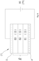
- a first exemplary embodiment of a tool 1 according to the invention for producing a particle foam part has two mold halves 2, 3 ( 1 ).
- a first (lower in the figure) mold half 2 is formed from a bottom wall 7 and a peripheral side wall 8 .
- a first capacitor plate 4 is arranged on the outside of the bottom wall 7 .
- the other, namely a second mold half 3 (upper in the figure) has a boundary wall 10 and a peripheral side wall 11 and is designed as a kind of punch which can be inserted with little play into the area bounded by the peripheral side wall 8, so that a mold cavity 13 is delimited between the two mold halves 2, 3, the side wall 11 of the second mold half 3 pointing away from the mold cavity 13.
- the second mold half 3 is thus referred to as the stamp mold half 3 and the first mold half 2 as the female mold half 2 .
- a plurality of webs 12 protrude from the boundary wall 10 on the same side as the side wall 11 .
- the webs 12 are connected to the side wall 11 and end at a level on which a second capacitor plate 5 rests.
- the webs 12 and the side wall 11 of the stamp mold half 3 are thus supports within the meaning of the invention, which are used to support the boundary wall 10 on the second capacitor plate 5.
- the second capacitor plate 5 has a waveguide connection 6 for connecting a waveguide.
- the side walls 11 and webs 12 of the stamp mold half 3 each form cavities 15 with one another and with the boundary wall 10, which cavities each have an opening 14 at the top.
- the second capacitor plate 5 is connected or connectable to a piston rod of a press in order to move the male mold half 3 with respect to the female mold half 2 and in particular to insert the male mold half 3 into the female mold half 2 (direction of an outlined arrow in FIG 1 ).
- a filling opening 9 for feeding foam particles into the mold cavity 13 is formed on the side wall 8 of the female mold half 2 ( 1 ). Furthermore, a ventilation opening (not shown) can also be provided on the side wall 8, from which the air can escape when the mold cavity 13 is filled.
- the tool 1 is provided in order to produce particle foam parts by welding foam particles introduced into the mold cavity 13 by means of electromagnetic waves.
- the first capacitor plate 4 can be connected to ground or earth and the second capacitor plate 5 can be connected to a wave generator via the waveguide connection 6 .
- a wave generator such as an RF or microwave generator is connected, a high-frequency electromagnetic field is generated in the mold cavity 13 .
- the foam particles are melted or melted and welded together by the energy of the electromagnetic field.
- the strength of the electromagnetic field prevailing in the mold cavity 13 depends on the properties of the substances present between the capacitor plates 4, 5, in particular on their relative permittivity ⁇ r.
- the relative permittivity ⁇ r is defined as the ratio of the permittivity of a material or medium to the permittivity of the vacuum, the electric field constant ⁇ 0.
- the relative permittivity ⁇ r depends on the material and can be understood as a measure for the field-weakening effects of a dielectric polarization of the material. The greater the relative permittivity ⁇ r of a material, the greater the field weakening.
- the mold halves 2, 3 are transparent (i.e. fundamentally transmissive) to electromagnetic waves, in particular those having a wavelength of the waves generated by the wave generator. That is, at least the bottom wall 7 of the female mold half 2 and the boundary wall 10 of the stamp mold half 3 are made of a dielectric material, which includes, for example, plastic, wood, ceramics, glass or the like.
- the foam particles introduced into the mold cavity 13 also have dielectric properties. Not only with an irregular geometry of the mold cavity 13, but also with locally different materials of the foam particles and influences from the mold halves 2, 3 themselves, locally different field strengths of the electromagnetic field can prevail in the mold cavity 13 or in the particle foam part to be formed and/or or the energy of the electromagnetic field is locally absorbed to different extents by the foam particles in the mold cavity 13 .
- Such irregular field strengths and/or degrees of absorption can be desirable, for example because the melting capacity of different foam materials can also differ, but they can also be undesirable. This can lead to insufficient or excessive heating and thus to undesirable fusion results of the foam particles.
- the cavities 15 of the male mold half 3 are provided, which reduce the mass of material in the male mold half 3 considerably. This in turn leads to an advantageous reduction in the influence on the electromagnetic field strength in the mold cavity 13, which considerably improves the flexibility in use and in the shaping of the mold cavity 13 and the stamp mold half 3.
- the cavities 15 can be used to trim the stamp mold half 3 in order to influence the electromagnetic field in the mold cavity 13 .
- the electromagnetic field in the mold cavity 13 can be influenced by suitable trimming in such a way that a uniform or otherwise desirable distribution of the field strength prevails in the mold cavity 13 .
- the foam particles are melted too much or even burned or charred at the points of higher compression and/or the welding of the foam particles is not sufficient at the adjacent points. Therefore, it may be desirable to have the field strength lower at the locations of higher densification of the foam particles than at the adjacent locations.
- material mixes with sections of more strongly absorbent foam particles and sections of less strongly absorbent foam particles.
- the tool 1 and the foam selection have been coordinated in advance using models or tests, but later in series production deviations in the fusion behavior occur, for example due to the use of a changed recipe or just a different batch of foam particles. In all of these cases it may be desirable to influence the electromagnetic field in the mold cavity 13.
- trimming bodies 30 can be inserted into the cavities 15 through the openings 14 ( 3 ).
- the shims 30 are made of a dielectric material. Due to the polarizing properties of a dielectric, the alternating electromagnetic field is weakened by the dielectric lying in the path of the field lines. On the other hand, in areas on the path of the same field lines that are kept free by the dielectric, the field is not weakened or even strengthened. The electrical field can thus be influenced in different ways by trimming bodies 30 of different size, shape and permittivity.
- the side walls 3 and webs 12 of the stamp mold half 3 can have shoulders 41 in the area of the openings 14 and the trimming bodies 30 can have rims 42 or similar shape features on the upper side when inserting the trimming body 30, support it on the shoulders 41 ( Figure 4A ).
- the side walls 3 and webs 12 of the stamp mold half 3 can have locking elements 43 in the area of the openings 14 or continuously or in other areas, and the trimming bodies 30 can have corresponding shape features on the side, which snap into the locking elements 43 when the trimming bodies 30 are inserted ( Figure 4B ).
- trimming bodies 30 may be designed to hold in cavities 15 by sheer friction.
- trimming bodies 50 can also be formed by inserting a moldable dielectric material into the cavities 15 to be trained ( figure 5 ).
- the trimming bodies 50 can be attached particularly easily to the inside of the boundary wall 10 .
- the dielectric material of the trimming bodies 50 can be curable after insertion or can be highly tough and preferably adhesive to the material of the second mold half 3 .
- the trimming bodies 30, 50 are preferably made of a material with a relative permittivity ( ⁇ r) of at least 2.
- ⁇ r relative permittivity
- the smaller the relative permittivity ⁇ r of the material of the trim body the more precisely and finely the electric fields in the mold cavity can be adjusted. Therefore, materials with a small relative permittivity ⁇ r, for example less than 2, can also be useful.
- the second mold half 3 is prepared as a function of preliminary tests or simulations with primary trimming bodies 30, 50 and later on the basis of actual, possibly changing conditions in series production, which are reflected in the foaming result, with secondary trimming bodies 30, 50 is fine-trimmed.
- the primary trimming bodies can be used as trimming bodies 50 made of a malleable mass ( figure 5 ) be designed, while the secondary shims as shims 30 fixed geometry ( 3 ) are configured, or vice versa, or one of the two.
- a primary trimming body 30 of fixed geometry has a further cavity into which a secondary trimming body 30, 50 of fixed geometry or of a moldable mass can be introduced.
- the cavities 15 are only partially filled with a trimming body 30,50. This makes it possible for the remaining space to be used for temperature control with a temperature control medium.
- the side wall 11 of the stamp mold half 3 can have a fluid inflow opening 61 and a fluid outflow opening 62 and the webs 12 can have fluid throughflow openings 63 ( 6 ).
- a fluid flow connection 64 is provided at the fluid inflow opening 61 and is connected to a fluid source 67 via a valve 66 .
- a fluid return connection 65 is provided at the fluid outflow opening 62 which—depending on the fluid used and depending on the process management—leads to the outside, the environment or, possibly via a treatment device, back to the fluid source 67 .
- a tempering fluid can be passed through the cavities 15 of the stamp mold half 3, for example to preheat the tool 1, to cool the mold cavity 13 or a particle foam body located therein, or in general to achieve a desired temperature control.
- trimming bodies 30, 50 Depending on the type and arrangement of the trimming bodies 30, 50 used (cf. Figs. 3 , 5 ) be arranged in the upper area of the cavities 15 or in the lower area of the cavities 15, so that a flow through the tempering fluid is not impeded by the trimming bodies 30, 50. If the fluid flow openings 63 are arranged both in the upper area and in the lower area of the cavities 15, as in the exemplary embodiment shown, different types of trimming bodies 30, 50 can be used as an alternative.
- the fluid inflow and outflow openings 61, 62 are preferably at the level of the fluid through-flow openings 63 or, if the fluid through-flow openings 63 are arranged both in the upper region and in the lower region of the cavities 15, at a level which lies between the heights of the fluid through-flow openings 63 . If a trimming body 30 of fixed geometry is so large that it protrudes into the area of the fluid flow openings 63 , transverse bores can be provided in such a trimming body 30 at the height of the fluid flow openings 63 .
- the fluid inflow and outflow openings 61, 62 and the fluid flow openings 63 are connected by small tubes or the like are. Even if the fluid inflow and outflow openings 61, 62 are provided on opposite sides of the stamp mold half 3 in the exemplary embodiment shown, they can also be arranged on the same side or on adjacent sides depending on the fluid routing inside the stamp mold half 3.
- a seal can be provided on the contact surface of the second capacitor plate 5, the seal being an edge seal on the side of the second mold half 3 or a surface seal on the side of the second capacitor plate 5 can be designed. If necessary, the pairing of materials between the second mold half 3 and the second capacitor plate 5 can also have a sufficient sealing effect during operation (ie under pressure).
- the mold halves 2, 3 are each made from a single molded part.
- the side wall 8 of the first mold half 2 can be attached to the bottom wall 7 .
- the bottom wall 7 of the first mold half 2 can be omitted if a sufficient seal is ensured between the side wall 8 and the first capacitor plate 4 in use (i.e. under pressure). This can be accomplished by a specially provided seal or by the pairing of materials between the first mold half 2 and the first capacitor plate 4 .
- the capacitor plates 4 , 5 are not part of the tool 1 .
- one or both of the capacitor plates 4 , 5 can be part of the tool 1 .
- the bottom wall 7 of the female mold half 2 can have the first capacitor plate 4 or can first capacitor plate 4 form the bottom wall 7 of the female mold half 2 .
- the first capacitor plate 4 can be attached to the side wall 8 of the female mold half 2 (e.g. screwed, glued, cast on, etc.) or integrated into the bottom wall 7 of the female mold half 2 (e.g. cast in, inserted in a pocket, etc. ) be.
- the openings 14 opening into the cavities 15 are provided at the upper edge of the stamp mold half 3 in the exemplary embodiments shown, the invention is not restricted to this. Rather, in variant embodiments, the openings 14 can also be provided in a side wall 11 of the stamp mold half 3, while the upper side of the stamp mold half 3 is closed. Openings 14 can also be provided in the webs 12 in order to get from one side into regions of the stamp mold half 3 lying further inwards.
- the second capacitor plate 5 can be connected to the stamp mold half 3 or can form a component with it.
- the second capacitor plate 5 can be attached to the side wall 11 of the stamp mold half 3 (e.g. screwed, glued, cast on, etc.) or integrated into a cover wall (if present) of the stamp mold half 3 (e.g. cast, inserted in a pocket , etc.).
- the side walls 8, 11 of the mold halves 2, 3 are formed from an electrically conductive material and that they are conductively connected to the capacitor plates 4, 5 or are formed in one piece. If the side walls 8, 11 of both mold halves 2, 3 are designed to be electrically conductive, they are coated with an electrically insulating layer, in particular a plastic layer, at least in the areas in which they touch.
- the peripheral side wall 8 is preferably not electrically conductive, e.g. made of plastic, so that there are no very small distances between the capacitor plates at the edge area, which would lead to locally very strong electric fields.
- the representation of the geometry of the mold halves 2, 3, the mold cavity 13 and the cavities 15 is purely exemplary and is entirely dependent on the type and shape of a particle foam body to be produced.
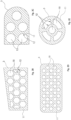
- the cavities 15 can also be rectangular or square and arranged in the manner of a matrix of, for example, two rows of four cavities 15 each ( Figure 2A ).
- the cavities 15 can be more or less dense and the cavities 15 can also have different cross-sectional shapes and sizes.
- the cavities can also be hexagonal in cross section ( Figure 2B ) or circular ( Figure 2C or more densely packed 2D ) or be shaped differently.
- the cavities 15 can, for example, be like a piece of cake ( Figure 2E ), or surrounding a circular cavity 15 in the manner of a ring segment (Fig. 2F).
- the cross-sectional shapes of the mold half 3 shown in the figures are entirely exemplary.
- the mold half 3 can be made in one piece with the cavities 15 and in one operation, for example by a casting process.
- the cavities 15 can also be subsequently incorporated into the mold half 3, for example by drilling from a solid block.
- the female mold half (first mold half) 2 can also be designed with cavities in a corresponding manner, in addition to or as an alternative to the stamp mold half 3.
- the upper capacitor plate 5 is provided with a circumferential edge web which surrounds the side wall 11 of the stamp mold half 3 .
- This edge web can serve to center and stabilize the side wall 11, but is entirely optional and can also be omitted.
- side walls 8, 11 are each described as a single, circumferential side wall, individual sections of the side walls 8, 11 adjoining one another in the circumferential direction can also be referred to as side walls.
- the tool 1 can be designed as a cracking tool and as such used in operation in basically three different positions, an open position (not shown) in which the two mold halves 2, 3 are completely separated from one another, so that a mold made with the mold Particle foam part can be removed from the mold, an intermediate position (not shown), in which the stamp mold half 3 is inserted so far into the female mold half 2 that the mold cavity 13 is closed, but the mold cavity 13 is not yet closed to its final volume Position ( Figs. 1 , 3 , 5 , 6 ) is reduced.
- the filling opening 9 and any ventilation opening are not covered by the stamp mold half 3, so that these through-openings communicate with the mold cavity 13 and foam particles can be filled in or air can be discharged.
- the mold cavity 13 is filled with foam particles. Thereafter, the stamp mold half 3 is pressed a little further into the female mold half 2, with the foam particles located therein being compressed.
- the tool 1 can be used in a device 70 for producing particle foam parts ( 7 ).
- a device 70 for producing particle foam parts has a reservoir 71 which is connected to the tool 1 with the filling hose 72 .
- the tool 1 is arranged in a press 73, which has a press table 74, a press ram 75, a cylinder-piston unit 76 for moving the press ram 75 and a stable frame 77 on which the cylinder-piston unit 76 and the press table 74 are attached.
- the press punch 75 is formed of an electrically conductive metal plate.
- the press ram 75 is connected to a wave generator 79 via a wave line 78, for example in the form of a coaxial cable.
- the press table 74 has an electrically conductive metal table top which is connected to ground via an electrically conductive base plate.
- the tool 1 is initially in an intermediate position.
- the stamp mold half 3 is inserted so far into the female mold half 2 that the mold cavity 13 is essentially closed.
- the tool 1 is inserted into the press 73 in this intermediate position.
- the filling hose 72 is connected to the filling opening 9 of the tool 1.
- Foam particles are supplied to the mold cavity 13 from the storage container 71 . If the mold cavity 13 is completely filled with foam particles, then the cylinder/piston unit 76 is actuated in order to press the two platens 13, 16 and thus the two mold halves 2, 3 together. The tool 1 is thus brought into the closed position. As a result, the foam particles located in the mold cavity 13 are compressed.
- the filling opening 9 of the matrix mold half 2 is covered by the stamp mold half 3 and thus closed.
- the filling hose 72 can then be pulled off the tool 1.
- a plug which has a similar dielectric constant as the side wall 8 can then be inserted into the filling opening 9 .
- the wave generator 79 In the compressed or closed state of the tool 1, the wave generator 79 generates an electromagnetic high-frequency signal (RF or microwave signal) which is applied via the waveguide 78, the press stamp 75 to the upper capacitor plate 5 of the stamp mold half 3.
- the waveguide 78 can be hollow and can have a core.
- the lower capacitor plate 4 of the female mold half 2 is connected to ground via the press bed 74 .
- the capacitor plates 4, 5 are electrically insulated from one another by the electrically non-conductive base bodies of the mold halves 2, 3, so that they form a plate capacitor which surrounds the mold cavity 13. Through the electromagnetic generated in this way Field, the foam particles are heated and welded together to form a particle foam part.
- the press 73 can be opened so that the tool 1 can be removed. If the tool has locking devices, it can be removed in the closed state. It can then be cooled by suitable cooling means such as a fan. While the tool 1, in which a particle foam part has already been formed, is being cooled, another tool 1 can be inserted into the press 73.
- the two mold halves 2, 3 are loosened, if necessary, the stamp mold half 3 is lifted off, and the particle foam part can be removed from the mold accordingly.
- the capacitor plates 4 , 5 are part of the device 70 and can be used for a large number of tools 1 . In particular, they also serve as pressing plates in the device 70. In this context, it is also irrelevant whether the tool 1 is in 1 Etc. shown orientation from above and below or vice versa between the capacitor plates 4, 5 is inserted.
- both mold halves 2, 3 are formed with cavities 15 for trimming the respective mold halves in order to influence an electromagnetic field within the mold cavity 13 ( 12 ).
- the first mold half 2 is basically constructed analogously to the second mold half 3 in this respect, so that the webs 12 and the side wall 8 of the first mold half 2 form supports for the first capacitor plate 4 .
- the webs 12 are also not formed in one piece with the mold halves 2, 3 as in previous exemplary embodiments, but are used as independent components in corresponding grooves on the side of the boundary walls 10 facing away from the mold cavity 13. If necessary, corresponding, vertically running grooves can also be provided in the inner surfaces of the side walls 8, 11 of the mold halves 2, 3 in order to give the webs 12 support. Alternatively or additionally, the webs 12 can also be glued, welded, or clamped between the side walls 8, 11.
- the invention is also not limited to the crack cracking process.
- the mold halves 2, 3 are not designed as punches and dies, but abut one another at the front with their side walls 8, 11.
- the side walls 8, 11 have gradations 120 that match one another, in order to seal off the mold cavity 13 when the process pressure builds up.
- the tool 1 of this exemplary embodiment a filling opening 121, which remains free when the mold 1 is closed and to which a filling injector 122 can be connected, with which the foam particles are introduced into the mold cavity 13.
- the inventors of the present application made simulations on the effect of the present invention.
- a simplified model was considered using a substitute image ( 8 ).
- the capacitor plates 4, 5 are connected to a voltage source 80, which corresponds to a polarization state of the wave generator 79. Accordingly, the capacitor plates 4, 5 are oppositely charged.
- an electromagnetic field E forms between the capacitor plates 4, 5, the strength of which depends on the respective permittivities of the regions 81, 82, 83.
- Field strength profiles of the electromagnetic field E between the capacitor plates 4, 5 can be calculated with this model. If required or for further approximation of specific forms of the tool 1 or a tool system with trimming bodies, further areas can be defined.
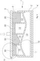
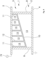
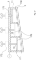
- a model provides in section two side walls 8 of the first mold half 2 extending between the capacitor plates 4, 5 ( 9 ).
- a bottom wall (Bz. 7 in Figs. 1 , 3 , 5 , 6 ) is not provided in this model.
- the capacitor plates 4, 5 project laterally beyond the side wall 8 of the first mold half 2.
- the first capacitor plate 4 is grounded, the second capacitor plate 5 is connected to a wave generator 79.
- a boundary wall 10 of the second mold half 3 extends between the side walls 8 in an oblique straight line.
- Side walls 11 and webs 12 ie, supports 11, 12 in the sense of the invention) lead from the boundary wall 10 to the second capacitor plate 5 in order to leave cavities 15 between them (on average six cavities 15, without loss of generality).
- a mold cavity 13 which is wedge-shaped in this model, is defined between the first capacitor plate 4, the side walls 8 of the first mold half 2 and the boundary wall 10.
- the practically vanishing field weakening in the supports 11, 12 is surprising at first, since a field weakening in the magnitude of the boundary wall 10 would initially be expected due to the dielectric properties. Such a field weakening in the supports 11, 12 would also lead to a significant inhomogeneity of the field in the mold cavity 13 compared to the supports 11, 12 and would be difficult to handle.
- the inventors of the present application have determined through theoretical considerations, simulations and tests that such an effect does not exist, which makes the implementation of the invention practicable. A theoretical explanation for this behavior becomes possible if the arrangement between the capacitor plates 4, 5 is divided into narrow elements in the width direction and the elements are first considered individually and then superimposed.
- a development of the invention provides, as a further exemplary embodiment, that the trimming of the mold half can be changed during a foaming process.
- the foaming process here includes a period of time from the introduction of the foam particles to the removal of the particle foam body. Of course, this does not rule out that the trimming is also changed before and/or after the foaming process.
- a trimming body in the form of a fluid is used and this fluid is supplied to the cavity or cavities and/or removed from the cavity or cavities via trimming fluid lines.
- the mold half and/or the associated capacitor plate is/are designed in such a way that this can also take place during a foaming process, ie in particular when the mold is mounted between the capacitor plates and/or when the mold cavity is closed.
- the trimming fluid can also be supplied/removed via a trimming fluid supply unit, which is arranged between the mold half and the capacitor plate.
- a trimming fluid supply unit for example, water, an oil or a viscous liquid (e.g. gel) can be used as the trimming fluid.
- a fluid with a low relative permittivity is preferably selected as the trimming fluid.
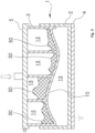
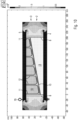
- bores 130 are provided in the side walls 11 and the webs 12, which communicate with the cavities 15 in the second mold half 3 ( 13 ).
- the bores 130 are each formed from one side through a side wall 11 continuously over the entire length or width of the mold half 3 through all webs 12 lying in a line to the last cavity 15 lying on the line and each form at least an opening 131 in a side wall 11 from.
- a trimming fluid supply port 132 is attached with a valve, which has a feed pump 133 with a Trimming fluid reservoir 134 is connected.
- a valved trim fluid drain port 135 which is connected to the trim fluid reservoir 133 via a trim fluid drain pump 136 .
- a valved supply air connection 137 is attached to another of the openings 131 and a valved venting connection 138 is attached to a last of the openings 131 .
- the supply air connection 137 and the venting connection can each be equipped with a fluid barrier.
- the air supply port 137 may be connected to a compressed air tank or air supply pump, and the vent port 138 may be connected to a vacuum tank or vacuum pump.
- the trimming fluid supply connection 132 and the venting connection 138 are opened and the feed pump 133 is put into operation in order to supply trimming fluid from the trimming fluid reservoir 134 to the cavities 15 .
- All cavities 15 are reached by the communicating connection via the bores 130 . Excess air can escape via the vent port 138 .
- the trimming fluid supply port 132 and the venting port 138 are closed and the charge pump 133 is turned off.
- the amount of trimming fluid can be set in advance. Reaching the predetermined quantity can be determined, for example, by measuring the flow at the feed pump 133 or by designing it as a metering pump. Alternatively, complete filling of the cavities 15 can be detected by triggering a fluid blockage of the vent port 138 .
- the trimming fluid discharge connection 135 and the air supply connection 137 are opened and the trimming fluid discharge pump 136 is put into operation in order to withdraw trimming fluid from the mold half 3 and feed it back to the trimming fluid reservoir 134.
- the trimming fluid can also be circulated. All cavities 15 are reached by the communicating connection via the bores 130 .
- the cavities 15 can be kept pressureless via the air supply connection 137 or the removal of trimming fluid can be supported via compressed air.
- the trim fluid discharge port 135 and the supply air port 137 are closed and the trim fluid drain pump 136 is switched off.
- the trimming fluid supply connection 132 and/or the trimming fluid discharge connection 135 can each optionally be configured without a valve if the respective pump 133, 136 has corresponding blocking devices.
- the pumps 133, 136 may be integrated into or attached to the respective trimming fluid ports 132, 135, or the valves of the trimming fluid ports 132, 135 may be integrated into or attached to the respective pumps 133, 136.
- the bores 130 each end in the last cavity 15 on the bore line.
- the bores 130 can also go beyond the last cavity 15 and through the side wall 11 adjoining there. This increases the connection options and also enables adaptation to the conditions on the system side. Unneeded openings in the side walls 11 can be closed with blind plugs.
- the bores 130 can be formed on a first level in relation to a height of the mold half 3 and further bores (not explicitly shown) can be formed on a second, higher level, with the trimming fluid connections 132, 135 at the openings 131 are connected on the first level and the supply air port 137 and the exhaust port 138 are connected on the second level. Unused openings in the side walls 11 are then closed by blind plugs.
- passages in the side walls 11 and the webs 12 can also be substituted when the mold half 3 is formed by an additive manufacturing process. In this case, additional connections can also be created in the webs 12 without requiring a bore from the outside. The formation of unnecessary openings in the side walls 11 can also be avoided.
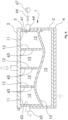
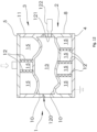
- respective covers 140 are arranged in the cavities 15 of the upper mold half 3, which divide the respective cavity into a trimming space 142 below the cover 140 and a pressure space 141 above the cover 140 ( 14 ).
- the lids 140 are urged upward by respective compression springs 148 located in the trimming space 142 .
- Trimming fluid lines 143 protrude through respective bores in the covers 140 and in the capacitor plate 5 adjoining the upper mold half 3 into the trimming space 142 of each cavity 15.
- the trimming fluid lines 143 converge outside the tool and are connected to a trimming fluid valve 144, which is designed here as a directional control valve is.
- trimming fluid can be fed from a trimming fluid reservoir 134 into the trimming fluid line 143 via the trimming fluid valve 144 via a trimming fluid feed pump 133 .
- the trimming fluid line 143 is connected to a return line into the trimming fluid reservoir 134 .
- all connections of the trimming fluid valve 144 are blocked.
- Compressed air lines 145 protrude through further bores in the capacitor plate 5 into the pressure chamber 141 of each cavity 15.
- the compressed air lines 145 converge outside of the tool and are connected to a compressed air valve 146, which is designed here as a directional control valve.
- the compressed air line 145 In a first switching position (neutral position), the compressed air line 145 is connected to the atmosphere.
- the compressed air line 145 is connected to a compressed air tank 147 .
- the trimming fluid valve 144 is switched from the neutral position to the first switching position, with the compressed air valve 146 being connected to the atmosphere in the first switching position, and the feed pump 133 is activated to pump trimming fluid from the trimming fluid reservoir 134 to the trimming spaces in the cavities 15 via the trimming fluid lines 143 . Due to the individual connection via the trimming fluid lines 143 to the trimming fluid feed pump 133, all of the cavities 15 are filled with trimming fluid simultaneously and rapidly. Excess air can escape via the compressed air valve 146 when the covers 140 in the cavities 15 are pushed up. When the cavities 15 are filled with a predetermined amount of trim fluid, the trim fluid valve 144 is switched to the neutral position, thus blocking a flow of trim fluid and the feed pump 133 is switched off.
- the amount of trimming fluid between the individual cavities 15 can adjust to one another. Reaching the predetermined quantity can be determined, for example, by measuring the flow at the feed pump 133 or by designing it as a metering pump.
- the trimming fluid valve 144 is switched to the second switching position and the compressed air valve is switched to the second switching position in order to apply compressed air to the pressure spaces 141 of the cavities 15.
- the compressed air in the pressure chambers 141 presses the lids 140 downwards, as a result of which the trimming fluid located in the trimming chambers 142 is pressed into the trimming fluid lines 143 and out of the mold half 3 and is fed back to the trimming fluid reservoir 134 .
- the trimming fluid can also be circulated. Due to the individual connection via the compressed air lines 145 to the compressed air tank 147, all cavities 15 are emptied simultaneously and quickly. When this process is complete, the trim fluid valve 144 is switched to the neutral position and the air pressure valve 146 is returned to atmosphere.
- trim fluid lines 143 may be individually connected to respective trim fluid valves for each cavity 15 .
- the trim fluid valves can be attached to the condenser plate 5 or housed or combined in a separate control unit.
- the trimming fluid valves can be constructed like the trimming fluid valve 144 and can be connected to the other paths via a common trimming fluid feed line to the trimming fluid feed pump 133 or via a common trimming fluid return line to the trimming fluid reservoir 134.
- the compressed air lines 145 can be individually connected to respective compressed air valves for each cavity 15 .
- the compressed air valves can be attached to the condenser plate 5 or housed or combined in a separate control unit.
- the compressed air valves can be constructed like the compressed air valve 146 and with the respective other paths via a common compressed air collection line with compressed air tank 147 or, if necessary, connected to the atmosphere via a common vent line.
- sections of the trimming fluid lines 143 and/or the compressed air lines 145 can be attached separately to an inside and/or to an outside of the capacitor plate 5 .
- the bores in the capacitor plate 5 can be provided with threads, for example, so that an inner part of the trimming fluid lines 143 and/or the compressed air lines 145 can be screwed to the inside of the capacitor plate 5 and an outer part of the trimming fluid lines 143 and/or the compressed air lines 145 to the Outside of the capacitor plate 5 can be screwed.
- an inner portion of the trim fluid lines 143 may be a piece of tubing with a threaded end.
- an inner part of the trimming fluid lines 143 can be of different lengths depending on the depth of the cavity 15 to be supplied.
- a connection plate (not shown in detail) can be provided, which carries sections of the trimming fluid lines 143 and/or the compressed air lines 145 pointing into the cavities 15 .
- the sections of the trimming fluid lines 143 can be designed, for example, as pipe pieces that can be firmly connected to the connection plate or can be attached to it, for example by screwing, plugging and/or gluing in corresponding bores.
- the sections of the compressed air lines 145 can be designed and attached in the same way or they can just be openings of corresponding bores, since the compressed air lines 145 do not have to protrude into the cavities 15 .
- connection plate 5 Holes in the capacitor plate 5 can be aligned with holes in the intermediate plate, so that the sections of the trimming fluid lines 143 and/or the compressed air lines 145 that are attached to the connection plate can be plugged through the holes in the capacitor plate 5 from the outside, so that a reliable Alignment of the connection plate and the capacitor plate is given.
- the external parts of the trimming fluid lines 143 and the compressed air lines 145 are then to be attached to the outside of the connection plate.
- the connection plate can be made of metal or plastic, for example.
- the connection plate can be produced conventionally by providing a plate and pieces of pipe, if necessary corresponding machining and assembly. Alternatively, the connection plate together with any pipe sections of the lines 143, 145 can be formed in one piece by an additive manufacturing process.
- connection plate can be arranged/can be arranged between the mold half 3 and the capacitor plate 5 .
- holes in the capacitor plate 5 can align with holes in the intermediate plate, although the external parts of the trimming fluid lines 143 and the compressed air lines 145 must then be attached to the outside of the capacitor plate 5 .
- short pieces of pipe can be used as sections of the compressed air lines 145 on the outside of the connecting plate be arranged and be plugged into the corresponding holes in the capacitor plate, so that a reliable alignment of the connection plate and the capacitor plate is also given in this case.
- connection plate is made of metal in this variant, it can act as a functional part of the capacitor plate 5 with regard to the generation of the electromagnetic field.
- connection plate is made of plastic in this variant, it can contribute to the dielectric effect of the mold half 3.
- a connection plate 150 can be provided ( 15 ) which receives or includes portions of the trimming fluid lines 143 and the compressed air lines 145, with the mold half facing portions of the lines 143, 145 opening in the face of the port plate 150 and the outward facing portions of the lines 143, 145 at one or more side edges Open the side edges of the connection plate 150.
- a switching unit with valves can also be arranged there.
- connection plate 150 can have the shape of a cuboid with an inner surface 151, an outer surface 152 opposite this, a first side surface 153, which connects the inner surface 151 and the outer surface 152, a second side surface 154, which adjoins the first side surface 153, and further side surfaces, which are opposite to the first side surface 153 and the second side surface 154, respectively.
- the inner surface 151 has a first set of bores 155 each carrying a piece of tubing 156 and a second set of bores 157 .
- the first side surface 153 carries, in a plane close to the outer surface 152, a group of third bores 158 which each meet a row of the first group of bores 155.
- the second side surface 154 carries in a plane close to the inner surface 151 a group of fourth bores 159 which each meet a row of the second group of bores 157 .
- the first group of holes 155 is arranged diagonally offset from the second group of holes 157 and the third group of holes 158 is arranged offset in height from the fourth group of holes 159, so that the holes 155 of the first group are only connected to holes 158 of the third group communicate and vice versa and the holes 157 of the second group communicate only with holes 159 of the fourth group and vice versa.
- the bores 155 of the first group with pipe sections 156 and the bores 158 of the third group each form sections of the trimming fluid line 143 and the bores 157 of the second group and the bores 159 of the fourth group each form sections of the compressed air line 145 (cf. 14 ), and the trimming fluid line 143 does not overlap with the compressed air line 145.
- All holes 155, 157, 158, 159 are preferably blind holes. If they are designed as through holes, one side should be sealed with blind plugs.
- the bores 158 of the third group can be connected to one another by a first collecting bore in the second side surface 154 or the side surface opposite thereto, and the bores 159 of the fourth group can be connected to one another by a second collecting bore in the first side surface 153 or the side surface opposite thereto Side surface are connected to each other. Then the bores 158, 159 of the third and fourth group can be closed by blind plugs, and only the first collecting bore needs to be connected to the trimming fluid valve 144 and the second collecting bore to the compressed air valve 146.
- the specific arrangement of the bores 155, 157, 158, 159 in 15 is to be understood entirely as an example.
- the bores 158, 159 of the third and fourth group can also be formed on a single side surface 153 or 154, in which case even on a single plane, without the trimming fluid line 143 and the compressed air line 145 overlapping.
- the arrangement shown has the advantage that the media trimming fluid and compressed air are separated from one another in terms of connection technology.
- connection plate 150 described here.
- a cover plate 160 can also be provided, which is arranged between the mold half 3 and the capacitor plate 5 and which has a number of projections which protrude into the cavities 15 and limit their volume ( 16 ).
- one or more bores 130 can be provided in the upper mold half 3, which forms a connection opening for trimming fluid in at least one side wall 11 and cuts through at least one of the webs 12 in order to fluidly connect several cavities 15 of the mold half 3.
- the arrangement of the bores is fundamentally arbitrary, as long as trimming fluid can be supplied and removed or passed through all cavities.
- the protrusions 161 are preferably sized so that the volumes remaining in the cavities 15 are of substantially equal height, but again this is optional and can be tailored to suit requirements.
- the protrusions 161 can be interchangeable elements of different heights attachable to the top plate.
- the bore(s) 130 is/are formed in such a way that they lie in the area of the volumes left by the projections 161, and also in such a way that all the volumes remaining in the cavities 15 can be filled with trimming fluid and emptied again as completely as possible.
- an opening formed through the bore 130 in the right side wall 11 at the top can serve as a supply connection for trim fluid and an opening formed through the bore 130 in the left side wall 11 at the bottom can serve as a drain connection for trim fluid, so that when trim fluid is both introduced and withdrawn, the Gravity exploited can be.
- the cover plate 160 can be produced by a casting method, by deep-drawing a plate, by milling and/or drilling from the solid, or by an additive method.
- additive manufacturing 3D printing
- no bores are required; instead, all connection and connection openings can be formed in one go with the additive structure of the cover plate 160.
- covers 170 can be provided, each of which is arranged in a height-adjustable manner in one of the cavities 15 and can be individually adjusted in height via a plunger 171 and a lifting drive 172 attached to the upper capacitor plate 5 ( 17 ).
- the plungers 171 are mounted in bores 173 in the upper capacitor plate.
- the tappets 171 can be designed as threaded rods, which are screwed into bores 173 designed with an internal thread, and can be rotated via a driving groove (not shown in detail) by the lifting drive 172 designed as a rotary drive, so that by turning in the (threaded) bores 173 a height adjustment can be effected.
- Other height adjustment devices are well known in the art and may alternatively be used as required.
- At least one bore 130 is provided for supplying the cavities 15 with trimming fluid; the above explanations apply in this regard.
- the lids can individually limit the volume of the cavities 15 ( 16 ). In this way, the relative permittivity of the mold half can not only be adjusted locally, but can also be changed during the foaming process.
- an expulsion of the trimming fluid via the bore 130 can also be assisted by closing the cover.
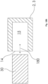
- one of the mold halves 2, 3 can also have a side opening or a plurality of side openings 14, into which a mold body 30 can be inserted and removed from the side ( 18A , direction of movement 180).
- the shaped body 30 can be comb-shaped with a base 181 and a plurality of cuboid prongs 182 ( Figure 18B ).
- several individual cuboid shaped bodies 30 can also be used, which can be moved into and out of the cavities 15 in an individually controlled manner.
- a tool system with such mold halves 2, 3 and mold body 30 is particularly, but not only, suitable for the production of particle foam boards with the help of electromagnetic waves.
- several shaped bodies 30 can be provided in the form of plates of the same shape as described above but of a lower height, which together fill the cavities 15 and can be moved in and out of the cavities 15 in an individually controlled manner ( Figure 18C ).
- Pumps 133, 136, connections 132, 135, 137, 138, valves 144, 146, tanks 134, 147, lines 143, 145 and other piping can be individual and in any arrangement and/or be a sub-combination part of a trimming fluid supply device.
- a controller for controlling all process operations described, including the activation of motors, pumps, valves and the provision of suitable sensors for providing process and status data for the controller as required, is self-evident and requires no further explanation.
Landscapes
- Physics & Mathematics (AREA)
- Health & Medical Sciences (AREA)
- Electromagnetism (AREA)
- Toxicology (AREA)
- Oral & Maxillofacial Surgery (AREA)
- Thermal Sciences (AREA)
- Engineering & Computer Science (AREA)
- Mechanical Engineering (AREA)
- Moulds For Moulding Plastics Or The Like (AREA)
- Molding Of Porous Articles (AREA)
Claims (15)
- Outil (1) pour la fabrication de pièces en mousse particulaire par soudage de particules de mousse moyennant des ondes électromagnétiques, comprenant deux moitiés de moule (2, 3), lesquelles délimitent une cavité de moule (13), sachant qu'au moins une, de préférence chacune, des deux moitiés de moule (2, 3) est constituée par un matériau transparent pour des ondes électromagnétiques et présente une paroi de délimitation (10) délimitant la cavité de moule (13) et un ou plusieurs supports (11, 12), lesquels servent à soutenir la paroi de délimitation (10) au niveau d'une plaque de condensateur (4, 5) du côté opposé à la cavité de moule (13) et constituent un ou plusieurs espaces creux (15).
- Outil (1) selon la revendication 1,
caractérisé en ce que
la paroi de délimitation (10) est constituée avec une épaisseur sensiblement constante. - Outil (1) selon la revendication 1 ou 2,
caractérisé en ce que
les supports (11, 12) s'étendent de manière approximativement parallèle à une direction de presse, dans laquelle les moitiés de moule (2, 3) sont comprimées avec une presse (73) lors du fonctionnement. - Outil (1) selon l'une des revendications précédentes,
caractérisé en ce que
il présente des raccords (64, 65) pour un fluide de mise à température qui peut traverser l'un ou les plusieurs espaces creux. - Outil (1) selon l'une des revendications précédentes,
caractérisé en ce que
l'au moins une des deux moitiés de moule (2, 3) est constituée pour l'ajustement de la moitié de moule (2, 3) moyennant l'un ou les plusieurs des supports (11, 12) et/ou du ou des plusieurs espaces creux (15) pour influencer un champ électromagnétique dans la cavité de moule (13). - Outil (1) selon l'une des revendications précédentes,
caractérisé en ce quele ou au moins un des plusieurs espaces creux (15) présente une ouverture (14), laquelle est de préférence tournée du côté opposé à la cavité de moule (13), et par laquelle un corps d'ajustement (30, 50) peut être inséré dans l'espace creux (15),sachant que le ou au moins un des plusieurs espaces creux (15) présente de préférence un élément de forme ou d'encliquetage (41, 43) pour le positionnement et/ou la fixation d'un corps d'ajustement (30, 50) dans le corps creux (15). - Outil (1) selon l'une des revendications précédentes,
caractérisé en ce quel'au moins une moitié de moule (2, 3) présente au moins un raccord (132, 135) pour un fluide d'ajustement en particulier liquide ou huileux ou visqueux, qui est relié à au moins un de l'un ou des plusieurs espaces creux (15), sachant que de préférence plusieurs espaces creux (15) sont reliés entre eux de manière fluidiquement communicante ou au moins des volumes partiels de plusieurs espaces creux (15) sont isolés les uns des autres de manière fluidiquement étanche,sachant que de préférence l'au moins une moitié de moule (2, 3) présente au moins un raccord pour air comprimé et/ou vide, qui est relié à au moins un de l'un ou des plusieurs espaces creux (15), sachant que de préférence l'au moins un raccord pour air comprimé et/ou vide est disposé sur un plan plus élevé que l'au moins un raccord (132, 135) pour un fluide d'ajustement. - Outil (1) selon la revendication 4 ou 7,
caractérisé en ce que
les espaces creux (15) sont reliés par des ouvertures de liaison (63) dans les supports (11, 12), sachant que les ouvertures de liaison (63) un ou groupe d'ouvertures de liaison (63) sont/est de préférence en alignement avec au moins un de raccords (64, 65, 132, 135) pour fluide de mise à température, fluide d'ajustement, air comprimé et/ou vide constitués dans une paroi latérale (11). - Système d'outil pour la fabrication de pièces en mousse particulaire,
caractérisé en ce quele système d'outil comprend un outil (1) selon l'une des revendications 1 à 8 et présente au moins un corps d'ajustement (30, 50) qui est constitué pour être placé dans le ou au moins un des espaces creux (15), et /ou un dispositif de mise à disposition de fluide d'ajustement qui est constitué pour alimenter l'au moins une moitié de moule (2, 3) en un fluide d'ajustement,sachant que le corps d'ajustement (30, 50) est constitué de préférence par un matériau ayant une permissivité relative (εr) d'au moins 2. - Système d'outil selon la revendication 9,
caractérisé en ce quele corps d'ajustement (30, 50) est constitué par un corps solide, en particulier comme corps enfichable destiné à être enfiché dans le ou au moins un des espaces creux (15), ou est fabriqué par garnissage d'un ou de plusieurs des espaces creux (15) moyennant un matériau durcissant,sachant que le corps d'ajustement (30, 50) présente de préférence un élément de forme (42) ou un élément d'encliquetage pour le positionnement et/ou la fixation dans le ou au moins un des espaces creux (15) ou peut être fixé par adhérence dans le ou au moins un des espaces creux (15). - Système d'outil selon la revendication 9 ou 10,
caractérisé en ce quele corps d'ajustement (30, 50) est constitué de telle manière qu'il ne remplisse qu'une zone partielle du ou d'un des espaces creux (15),sachant que la zone partielle est de préférence une zone partielle disposée de manière éloignée de la cavité de moule (13). - Système d'outil selon l'une des revendications 9 à 11,
caractérisé en ce que
il comprend plusieurs corps d'ajustement (30, 50) de différente taille et/ou en différents matériaux, lesquels présentent une permissivité relative (εr) différente. - Système d'outil selon l'une des revendications 9 à 12,
caractérisé en ce queil présente une plaque de raccordement qui doit être disposée entre une plaque de condensateur (4, 5) et une moitié de moule (2, 3) de l'outil (1) ou d'un côté d'une plaque de condensateur (4, 5) qui est opposé à une moitié de moule (2, 3) de l'outil (1) et qui présente des raccords de fluides et/ou canaux de fluides et/ou ouvertures de fluides pour l'amenée et/ou l'évacuation de fluides aux espaces creux (15) de la moitié de moule (2, 3) de ou vers l'extérieur,sachant que la plaque de raccordement présente de préférence des éléments de tube (143, 145) qui, en cas de montage conforme à la destination de la plaque de raccordement, s'avancent dans les espaces creux (15) de la moitié de forme (2, 3). - Procédé pour la fabrication d'une ou de plusieurs pièces en mousse particulaire par soudage de particules de mousse moyennant des ondes électromagnétiques, sachant qu'un outil (1) comprenant des moitiés de moule (2, 3) qui forment une cavité de moule (13) est disposé entre deux plaques de condensateur (4, 5), la cavité de moule (13) est remplie de particules de mousse, l'outil (1) est fermé par rapprochement des deux moitiés de moule (2, 3) et l'outil (1) avec les particules de mousse dans la cavité de moule (13) est exposé à des ondes électromagnétiques, en particulier des ondes radio ou des microondes, introduites via les plaques de condensateur (4, 5), sachant que les particules de mousse se réchauffent sous l'effet des ondes électromagnétiques et fusionnent ou cuisent au moins partiellement les unes avec les autres, sachant que le procédé est exécuté en utilisant un outil (1) selon l'une des revendications 1 à 8 ou un système d'outil selon l'une des revendications 9 à 13.
- Procédé selon la revendication 14,
caractérisé en ce queun ou plusieurs corps d'ajustement (30, 50) ou un fluide d'ajustement est/sont disposé/s dans le ou au moins un des espaces creux (15) pour influencer un champ électromagnétique dans la cavité de moule (13),sachant que, de préférence en fonction de la qualité du soudage des particules de mousse, la disposition d'un ou de plusieurs corps d'ajustement (30, 50) ou d'un fluide d'ajustement dans l'outil (1) est modifiée pour régler l'influence du champ électromagnétique dans la cavité de moule (13),et/ou la disposition d'un ou de plusieurs corps d'ajustement (30, 50) ou d'un fluide d'ajustement dans l'outil (1) est modifiée pendant une opération de moussage pour influencer dynamiquement un champ électromagnétique dans la cavité de moule (13).
Applications Claiming Priority (2)
| Application Number | Priority Date | Filing Date | Title |
|---|---|---|---|
| DE102019127680.2A DE102019127680A1 (de) | 2019-10-15 | 2019-10-15 | Werkzeug, Werkzeugsystem und Verfahren zum Herstellen von Partikelschaumstoffteilen |
| PCT/EP2020/077858 WO2021073924A1 (fr) | 2019-10-15 | 2020-10-05 | Outil, système d'outil et procédé de fabrication d'éléments en mousse particulaire |
Publications (2)
| Publication Number | Publication Date |
|---|---|
| EP4045255A1 EP4045255A1 (fr) | 2022-08-24 |
| EP4045255B1 true EP4045255B1 (fr) | 2023-09-06 |
Family
ID=72752445
Family Applications (1)
| Application Number | Title | Priority Date | Filing Date |
|---|---|---|---|
| EP20786292.1A Active EP4045255B1 (fr) | 2019-10-15 | 2020-10-05 | Moule, système de moule et procédé de fabrication des pièces en forme de particles mouseux |
Country Status (5)
| Country | Link |
|---|---|
| US (2) | US11865741B2 (fr) |
| EP (1) | EP4045255B1 (fr) |
| DE (1) | DE102019127680A1 (fr) |
| ES (1) | ES2958991T3 (fr) |
| WO (1) | WO2021073924A1 (fr) |
Families Citing this family (2)
| Publication number | Priority date | Publication date | Assignee | Title |
|---|---|---|---|---|
| DE102021204230A1 (de) | 2021-04-28 | 2022-11-03 | Adidas Ag | Vorrichtung, Verfahren und Kondensatorplattensatz zur Herstellung eines Partikelschaumstoffteils, insbesondere zur Herstellung einer Schuhsohle oder eines Teils einer Schuhsohle |
| DE102021110841A1 (de) | 2021-04-28 | 2022-11-03 | Kurtz Gmbh & Co. Kg | Vorrichtung, Verfahren und Kondensatorplatten-Set zur Herstellung eines Partikelschaumstoffteils |
Family Cites Families (18)
| Publication number | Priority date | Publication date | Assignee | Title |
|---|---|---|---|---|
| US3242238A (en) * | 1961-04-12 | 1966-03-22 | Edwin A Edberg | Method for making foamed polymeric structural materials |
| US3079723A (en) | 1961-10-27 | 1963-03-05 | Carl W Roes | Fishing lure |
| CA1011070A (en) * | 1972-05-30 | 1977-05-31 | Richard H. Immel | Method for bonding expanded polymeric parts |
| DE10009665C1 (de) * | 2000-02-29 | 2002-01-24 | Fraunhofer Ges Forschung | Verfahren und Vorrichtung zum thermischen Verbinden von Polymerschaumpartikeln |
| DE10156590A1 (de) | 2001-11-20 | 2003-05-28 | Fagerdala Deutschland Gmbh | Werkzeug und Verfahren zu seiner Herstellung |
| US20140243442A1 (en) | 2011-10-06 | 2014-08-28 | Jsp International Sarl | Moulding of plastic particulate matter |
| DE102012008536B4 (de) | 2011-10-06 | 2023-06-15 | Gb Boucherie Nv | Verfahren zum Herstellen von Bürsten sowie Bürste |
| DE102016100690A1 (de) * | 2016-01-18 | 2017-07-20 | Kurtz Gmbh | Verfahren und Vorrichtung zur Herstellung eines Partikelschaumstoffteils |
| US9965538B2 (en) | 2016-01-19 | 2018-05-08 | Microsoft Technology Licensing, Llc | Early thread return with secondary event writes |
| US10296418B2 (en) | 2016-01-19 | 2019-05-21 | Microsoft Technology Licensing, Llc | Versioned records management using restart era |
| DE102016014063A1 (de) * | 2016-11-25 | 2018-05-30 | Krallmann Kunststoffverarbeitung Gmbh | Verfahren und Vorrichtung zur Herstellung eines aus einem Partikelschaum bestehenden Formteils |
| TW201835800A (zh) | 2016-12-01 | 2018-10-01 | 國立健康與醫學研究所 | 用於確定/校正缺陷的方法和相關的裝置 |
| DE202017107149U1 (de) | 2016-12-01 | 2018-03-05 | Kurtz Gmbh | Crackspalt-Formwerkzeug zum Herstellen eines Partikelschaumstoffteils sowie Vorrichtung zum Herstellen eines Partikelschaumstoffteils |
| DE102016123214A1 (de) * | 2016-12-01 | 2018-06-07 | Kurtz Gmbh | Vorrichtung zur Herstellung eines Partikelschaumstoffteils |
| US10765274B2 (en) | 2016-12-01 | 2020-09-08 | Mami NAKAJIMA | Packaging container and method for using same |
| DE102016223980B4 (de) * | 2016-12-01 | 2022-09-22 | Adidas Ag | Verfahren zur Herstellung eines Kunststoffformteils |
| DE102017128895B4 (de) * | 2017-12-05 | 2024-01-11 | Kurtz Gmbh | Vorrichtung und Verfahren zur Herstellung eines Partikelschaumstoffteils |
| DE202018102138U1 (de) * | 2018-04-18 | 2019-07-19 | Kurtz Gmbh | Werkzeug und Vorrichtung zur Herstellung von geschäumten Dämmplatten |
-
2019
- 2019-10-15 DE DE102019127680.2A patent/DE102019127680A1/de active Pending
-
2020
- 2020-10-05 ES ES20786292T patent/ES2958991T3/es active Active
- 2020-10-05 WO PCT/EP2020/077858 patent/WO2021073924A1/fr unknown
- 2020-10-05 US US17/768,506 patent/US11865741B2/en active Active
- 2020-10-05 EP EP20786292.1A patent/EP4045255B1/fr active Active
-
2023
- 2023-11-28 US US18/521,157 patent/US20240091990A1/en active Pending
Also Published As
| Publication number | Publication date |
|---|---|
| EP4045255A1 (fr) | 2022-08-24 |
| US20230182350A1 (en) | 2023-06-15 |
| US20240091990A1 (en) | 2024-03-21 |
| DE102019127680A1 (de) | 2021-04-15 |
| WO2021073924A1 (fr) | 2021-04-22 |
| CN114981055A (zh) | 2022-08-30 |
| ES2958991T3 (es) | 2024-02-19 |
| US11865741B2 (en) | 2024-01-09 |
Similar Documents
| Publication | Publication Date | Title |
|---|---|---|
| EP4045255B1 (fr) | Moule, système de moule et procédé de fabrication des pièces en forme de particles mouseux | |
| DE102019215845B4 (de) | Verfahren zur Herstellung von geschäumten Partikelteilen, insbesondere für die Herstellung von Schuhsohlen | |
| EP2900390B1 (fr) | Système de dosage, procédé de dosage et procédé de fabrication | |
| WO2018100154A2 (fr) | Dispositif de fabrication d'un élément en mousse de particules expansées | |
| DE102007047314B4 (de) | Presswerkzeug zum Warmumformen oder/und Presshärten von Werkstücken aus Blech | |
| EP3405323A1 (fr) | Dispositif et procédé de fabrication d'une pièce en mousse particulaire | |
| EP2293909B1 (fr) | Procédé et dispositif de chauffage pour le thermoformage | |
| WO2003043795A1 (fr) | Moule destine a la production de pieces moulees en mousse a base de particules | |
| EP2576191A2 (fr) | Dispositif de modification d'espace de fabrication et dispositif pour fabriquer un objet tridimensionnel à l'aide dudit dispositif de modification d'espace de fabrication | |
| WO2018100169A2 (fr) | Moule pour injection-compression, pour la fabrication d'une pièce en mousse de particules expansées ainsi que dispositif pour produire une pièce en mousse de particules expansées | |
| DE3343210C1 (de) | Verfahren und Vorrichtung zur Herstellung verdichteter Formkoerper | |
| DE112019001894T5 (de) | Verfahren zur Herstellung von Komponenten für eine elektro-chemische Zelle und eine elektrochemische Zelle und Zellstapel | |
| DE2505618B2 (de) | Formwerkzeug | |
| CH703727A1 (de) | Verfahren zum Herstellen von Blechstapelkörpern. | |
| DE102015211170A1 (de) | Vorrichtung und Verfahren zum Herstellen eines dreidimensionalen Objekts | |
| DE102012100419A1 (de) | Spritzgusswerkzeug und Verfahren zur Herstellung eines Spritzgussbauteils, insbesondere eines Schallisolationsbauteils eines Kraftfahrzeugs | |
| EP0082913A2 (fr) | Procédé et dispositif pour la fabrication de pièces moulées essentiellement sèches en matière thermoplastique moussante, p.e. polystyrène | |
| DE102014113069A1 (de) | Anordnung und Verfahren zum Herstellen eines Faserverbundwerkstücks | |
| EP2857166B1 (fr) | Moule | |
| EP3088153B1 (fr) | Outil de formage | |
| DE112011105509T5 (de) | Flaches Wärmerohr und Verfahren zum Herstellen desselben | |
| CN114981055B (zh) | 用于生产颗粒泡沫部件的工具、工具系统和方法 | |
| AT520316B1 (de) | Verfahren und Vorrichtung zum Aufschäumen eines expansionsfähigen Partikelschaummaterials | |
| AT522063B1 (de) | Druckpresse zum Herstellen eines Laminatbauteiles sowie Verfahren zum Pressen eines Laminatbauteiles | |
| DE102021204230A1 (de) | Vorrichtung, Verfahren und Kondensatorplattensatz zur Herstellung eines Partikelschaumstoffteils, insbesondere zur Herstellung einer Schuhsohle oder eines Teils einer Schuhsohle |
Legal Events
| Date | Code | Title | Description |
|---|---|---|---|
| STAA | Information on the status of an ep patent application or granted ep patent |
Free format text: STATUS: UNKNOWN |
|
| STAA | Information on the status of an ep patent application or granted ep patent |
Free format text: STATUS: THE INTERNATIONAL PUBLICATION HAS BEEN MADE |
|
| PUAI | Public reference made under article 153(3) epc to a published international application that has entered the european phase |
Free format text: ORIGINAL CODE: 0009012 |
|
| STAA | Information on the status of an ep patent application or granted ep patent |
Free format text: STATUS: REQUEST FOR EXAMINATION WAS MADE |
|
| 17P | Request for examination filed |
Effective date: 20220507 |
|
| AK | Designated contracting states |
Kind code of ref document: A1 Designated state(s): AL AT BE BG CH CY CZ DE DK EE ES FI FR GB GR HR HU IE IS IT LI LT LU LV MC MK MT NL NO PL PT RO RS SE SI SK SM TR |
|
| DAV | Request for validation of the european patent (deleted) | ||
| DAX | Request for extension of the european patent (deleted) | ||
| GRAP | Despatch of communication of intention to grant a patent |
Free format text: ORIGINAL CODE: EPIDOSNIGR1 |
|
| STAA | Information on the status of an ep patent application or granted ep patent |
Free format text: STATUS: GRANT OF PATENT IS INTENDED |
|
| INTG | Intention to grant announced |
Effective date: 20230411 |
|
| GRAS | Grant fee paid |
Free format text: ORIGINAL CODE: EPIDOSNIGR3 |
|
| GRAA | (expected) grant |
Free format text: ORIGINAL CODE: 0009210 |
|
| STAA | Information on the status of an ep patent application or granted ep patent |
Free format text: STATUS: THE PATENT HAS BEEN GRANTED |
|
| AK | Designated contracting states |
Kind code of ref document: B1 Designated state(s): AL AT BE BG CH CY CZ DE DK EE ES FI FR GB GR HR HU IE IS IT LI LT LU LV MC MK MT NL NO PL PT RO RS SE SI SK SM TR |
|
| REG | Reference to a national code |
Ref country code: GB Ref legal event code: FG4D Free format text: NOT ENGLISH |
|
| REG | Reference to a national code |
Ref country code: CH Ref legal event code: EP |
|
| REG | Reference to a national code |
Ref country code: IE Ref legal event code: FG4D Free format text: LANGUAGE OF EP DOCUMENT: GERMAN |
|
| REG | Reference to a national code |
Ref country code: DE Ref legal event code: R096 Ref document number: 502020005175 Country of ref document: DE |
|
| REG | Reference to a national code |
Ref country code: LT Ref legal event code: MG9D |
|
| REG | Reference to a national code |
Ref country code: NL Ref legal event code: MP Effective date: 20230906 |
|
| PG25 | Lapsed in a contracting state [announced via postgrant information from national office to epo] |
Ref country code: GR Free format text: LAPSE BECAUSE OF FAILURE TO SUBMIT A TRANSLATION OF THE DESCRIPTION OR TO PAY THE FEE WITHIN THE PRESCRIBED TIME-LIMIT Effective date: 20231207 |
|
| PGFP | Annual fee paid to national office [announced via postgrant information from national office to epo] |
Ref country code: ES Payment date: 20231117 Year of fee payment: 4 |
|
| PG25 | Lapsed in a contracting state [announced via postgrant information from national office to epo] |
Ref country code: SE Free format text: LAPSE BECAUSE OF FAILURE TO SUBMIT A TRANSLATION OF THE DESCRIPTION OR TO PAY THE FEE WITHIN THE PRESCRIBED TIME-LIMIT Effective date: 20230906 Ref country code: RS Free format text: LAPSE BECAUSE OF FAILURE TO SUBMIT A TRANSLATION OF THE DESCRIPTION OR TO PAY THE FEE WITHIN THE PRESCRIBED TIME-LIMIT Effective date: 20230906 Ref country code: NO Free format text: LAPSE BECAUSE OF FAILURE TO SUBMIT A TRANSLATION OF THE DESCRIPTION OR TO PAY THE FEE WITHIN THE PRESCRIBED TIME-LIMIT Effective date: 20231206 Ref country code: LV Free format text: LAPSE BECAUSE OF FAILURE TO SUBMIT A TRANSLATION OF THE DESCRIPTION OR TO PAY THE FEE WITHIN THE PRESCRIBED TIME-LIMIT Effective date: 20230906 Ref country code: LT Free format text: LAPSE BECAUSE OF FAILURE TO SUBMIT A TRANSLATION OF THE DESCRIPTION OR TO PAY THE FEE WITHIN THE PRESCRIBED TIME-LIMIT Effective date: 20230906 Ref country code: HR Free format text: LAPSE BECAUSE OF FAILURE TO SUBMIT A TRANSLATION OF THE DESCRIPTION OR TO PAY THE FEE WITHIN THE PRESCRIBED TIME-LIMIT Effective date: 20230906 Ref country code: GR Free format text: LAPSE BECAUSE OF FAILURE TO SUBMIT A TRANSLATION OF THE DESCRIPTION OR TO PAY THE FEE WITHIN THE PRESCRIBED TIME-LIMIT Effective date: 20231207 Ref country code: FI Free format text: LAPSE BECAUSE OF FAILURE TO SUBMIT A TRANSLATION OF THE DESCRIPTION OR TO PAY THE FEE WITHIN THE PRESCRIBED TIME-LIMIT Effective date: 20230906 |
|
| PGFP | Annual fee paid to national office [announced via postgrant information from national office to epo] |
Ref country code: IT Payment date: 20231031 Year of fee payment: 4 Ref country code: FR Payment date: 20231010 Year of fee payment: 4 Ref country code: DE Payment date: 20231019 Year of fee payment: 4 |
|
| REG | Reference to a national code |
Ref country code: ES Ref legal event code: FG2A Ref document number: 2958991 Country of ref document: ES Kind code of ref document: T3 Effective date: 20240219 |
|
| PG25 | Lapsed in a contracting state [announced via postgrant information from national office to epo] |
Ref country code: NL Free format text: LAPSE BECAUSE OF FAILURE TO SUBMIT A TRANSLATION OF THE DESCRIPTION OR TO PAY THE FEE WITHIN THE PRESCRIBED TIME-LIMIT Effective date: 20230906 |
|
| PG25 | Lapsed in a contracting state [announced via postgrant information from national office to epo] |
Ref country code: IS Free format text: LAPSE BECAUSE OF FAILURE TO SUBMIT A TRANSLATION OF THE DESCRIPTION OR TO PAY THE FEE WITHIN THE PRESCRIBED TIME-LIMIT Effective date: 20240106 |
|
| PG25 | Lapsed in a contracting state [announced via postgrant information from national office to epo] |
Ref country code: SM Free format text: LAPSE BECAUSE OF FAILURE TO SUBMIT A TRANSLATION OF THE DESCRIPTION OR TO PAY THE FEE WITHIN THE PRESCRIBED TIME-LIMIT Effective date: 20230906 Ref country code: RO Free format text: LAPSE BECAUSE OF FAILURE TO SUBMIT A TRANSLATION OF THE DESCRIPTION OR TO PAY THE FEE WITHIN THE PRESCRIBED TIME-LIMIT Effective date: 20230906 Ref country code: IS Free format text: LAPSE BECAUSE OF FAILURE TO SUBMIT A TRANSLATION OF THE DESCRIPTION OR TO PAY THE FEE WITHIN THE PRESCRIBED TIME-LIMIT Effective date: 20240106 Ref country code: EE Free format text: LAPSE BECAUSE OF FAILURE TO SUBMIT A TRANSLATION OF THE DESCRIPTION OR TO PAY THE FEE WITHIN THE PRESCRIBED TIME-LIMIT Effective date: 20230906 Ref country code: CZ Free format text: LAPSE BECAUSE OF FAILURE TO SUBMIT A TRANSLATION OF THE DESCRIPTION OR TO PAY THE FEE WITHIN THE PRESCRIBED TIME-LIMIT Effective date: 20230906 Ref country code: PT Free format text: LAPSE BECAUSE OF FAILURE TO SUBMIT A TRANSLATION OF THE DESCRIPTION OR TO PAY THE FEE WITHIN THE PRESCRIBED TIME-LIMIT Effective date: 20240108 Ref country code: SK Free format text: LAPSE BECAUSE OF FAILURE TO SUBMIT A TRANSLATION OF THE DESCRIPTION OR TO PAY THE FEE WITHIN THE PRESCRIBED TIME-LIMIT Effective date: 20230906 |