EP4044737B1 - Kommunikationsverfahren und kommunikationsvorrichtung - Google Patents
Kommunikationsverfahren und kommunikationsvorrichtung Download PDFInfo
- Publication number
- EP4044737B1 EP4044737B1 EP19951921.6A EP19951921A EP4044737B1 EP 4044737 B1 EP4044737 B1 EP 4044737B1 EP 19951921 A EP19951921 A EP 19951921A EP 4044737 B1 EP4044737 B1 EP 4044737B1
- Authority
- EP
- European Patent Office
- Prior art keywords
- dci
- coreset
- coresets
- group index
- pdsch
- Prior art date
- Legal status (The legal status is an assumption and is not a legal conclusion. Google has not performed a legal analysis and makes no representation as to the accuracy of the status listed.)
- Active
Links
Images


Classifications
-
- H—ELECTRICITY
- H04—ELECTRIC COMMUNICATION TECHNIQUE
- H04W—WIRELESS COMMUNICATION NETWORKS
- H04W72/00—Local resource management
- H04W72/12—Wireless traffic scheduling
- H04W72/1263—Mapping of traffic onto schedule, e.g. scheduled allocation or multiplexing of flows
- H04W72/1273—Mapping of traffic onto schedule, e.g. scheduled allocation or multiplexing of flows of downlink data flows
-
- H—ELECTRICITY
- H04—ELECTRIC COMMUNICATION TECHNIQUE
- H04L—TRANSMISSION OF DIGITAL INFORMATION, e.g. TELEGRAPHIC COMMUNICATION
- H04L1/00—Arrangements for detecting or preventing errors in the information received
- H04L1/12—Arrangements for detecting or preventing errors in the information received by using return channel
- H04L1/16—Arrangements for detecting or preventing errors in the information received by using return channel in which the return channel carries supervisory signals, e.g. repetition request signals
- H04L1/1607—Details of the supervisory signal
- H04L1/1614—Details of the supervisory signal using bitmaps
-
- H—ELECTRICITY
- H04—ELECTRIC COMMUNICATION TECHNIQUE
- H04L—TRANSMISSION OF DIGITAL INFORMATION, e.g. TELEGRAPHIC COMMUNICATION
- H04L1/00—Arrangements for detecting or preventing errors in the information received
- H04L1/12—Arrangements for detecting or preventing errors in the information received by using return channel
- H04L1/16—Arrangements for detecting or preventing errors in the information received by using return channel in which the return channel carries supervisory signals, e.g. repetition request signals
- H04L1/18—Automatic repetition systems, e.g. Van Duuren systems
- H04L1/1812—Hybrid protocols; Hybrid automatic repeat request [HARQ]
-
- H—ELECTRICITY
- H04—ELECTRIC COMMUNICATION TECHNIQUE
- H04L—TRANSMISSION OF DIGITAL INFORMATION, e.g. TELEGRAPHIC COMMUNICATION
- H04L1/00—Arrangements for detecting or preventing errors in the information received
- H04L1/12—Arrangements for detecting or preventing errors in the information received by using return channel
- H04L1/16—Arrangements for detecting or preventing errors in the information received by using return channel in which the return channel carries supervisory signals, e.g. repetition request signals
- H04L1/18—Automatic repetition systems, e.g. Van Duuren systems
- H04L1/1829—Arrangements specially adapted for the receiver end
- H04L1/1861—Physical mapping arrangements
-
- H—ELECTRICITY
- H04—ELECTRIC COMMUNICATION TECHNIQUE
- H04L—TRANSMISSION OF DIGITAL INFORMATION, e.g. TELEGRAPHIC COMMUNICATION
- H04L5/00—Arrangements affording multiple use of the transmission path
- H04L5/003—Arrangements for allocating sub-channels of the transmission path
- H04L5/0053—Allocation of signalling, i.e. of overhead other than pilot signals
-
- H—ELECTRICITY
- H04—ELECTRIC COMMUNICATION TECHNIQUE
- H04W—WIRELESS COMMUNICATION NETWORKS
- H04W72/00—Local resource management
- H04W72/04—Wireless resource allocation
- H04W72/044—Wireless resource allocation based on the type of the allocated resource
-
- H—ELECTRICITY
- H04—ELECTRIC COMMUNICATION TECHNIQUE
- H04W—WIRELESS COMMUNICATION NETWORKS
- H04W72/00—Local resource management
- H04W72/20—Control channels or signalling for resource management
- H04W72/23—Control channels or signalling for resource management in the downlink direction of a wireless link, i.e. towards a terminal
-
- H—ELECTRICITY
- H04—ELECTRIC COMMUNICATION TECHNIQUE
- H04W—WIRELESS COMMUNICATION NETWORKS
- H04W72/00—Local resource management
- H04W72/50—Allocation or scheduling criteria for wireless resources
- H04W72/54—Allocation or scheduling criteria for wireless resources based on quality criteria
- H04W72/542—Allocation or scheduling criteria for wireless resources based on quality criteria using measured or perceived quality
-
- H—ELECTRICITY
- H04—ELECTRIC COMMUNICATION TECHNIQUE
- H04L—TRANSMISSION OF DIGITAL INFORMATION, e.g. TELEGRAPHIC COMMUNICATION
- H04L5/00—Arrangements affording multiple use of the transmission path
- H04L5/0001—Arrangements for dividing the transmission path
- H04L5/0014—Three-dimensional division
- H04L5/0023—Time-frequency-space
-
- H—ELECTRICITY
- H04—ELECTRIC COMMUNICATION TECHNIQUE
- H04L—TRANSMISSION OF DIGITAL INFORMATION, e.g. TELEGRAPHIC COMMUNICATION
- H04L5/00—Arrangements affording multiple use of the transmission path
- H04L5/003—Arrangements for allocating sub-channels of the transmission path
- H04L5/0053—Allocation of signalling, i.e. of overhead other than pilot signals
- H04L5/0055—Physical resource allocation for ACK/NACK
Definitions
- the present disclosure relates to the field of communications, and in particular to a communication method and a communication apparatus.
- 5G mobile communication systems support high-band communications.
- path loss during transmission may increase, resulting in a decrease in signal coverage.
- a solution to the above-mentioned problem is to adopt multiple-beam transmission on the basis of a large-scale antenna array, so as to increase the signal coverage.
- One of multiple-beam transmission schemes is multiple-physical downlink control channel (PDCCH) based scheme (multiple-PDCCH based scheme).
- PDCCH multiple-physical downlink control channel
- TRPs multiple transmission/reception points
- multiple antenna panels or multiple beams simultaneously transmit downlink data to a terminal device.
- CORESET control resource set
- Such index may be called a group index, or may be called another name.
- Group indexes of different CORESETs may be the same or different. For example, multiple CORESETs with the same group index may be referred to as one CORESET group.
- CORESET#0 is a special CORESET. At present, it is impossible to simultaneously configure a group index for CORESET#0 and group indexes for other CORESETs through a single radio resource control (RRC) signaling.
- RRC radio resource control
- the multiple-PDCCH based transmission scheme has many transmission processes related to the group index. How to use CORESET#0 in the multiple-PDCCH based transmission scheme is a problem that needs to be solved at present.
- the present disclosure provides a communication method, which may solve a problem of how to use CORESET#0 in a multiple-PDCCH based transmission scheme.
- a communication method including: receiving first configuration information, wherein the first configuration information is used to configure one or more CORESETs, at least one of the one or more CORESETs is configured with a respective group index, and the one or more CORESETs do not include CORESET#0; receiving, according to scheduling information transmitted on the one or more CORESETs and/or CORESET#0, a physical downlink shared channel (PDSCH) scheduled by the scheduling information; receiving first DCI on CORESET#0, wherein the first DCI is configured to schedule a first PDSCH; and in response that the first DCI meets a first preset condition, and that the first DCI and the first PDSCH correspond to the same component carrier, CC, receiving the first PDSCH according to a quasi co-location, QCL, assumption of a first CORESET.
- PDSCH physical downlink shared channel
- the first preset condition indicates that a time interval between the first DCI and the first PDSCH is less than a first threshold.
- the communication method further includes: receiving second DCI on CORESET#0, where the second DCI is configured to schedule a first channel state information-reference signal, CSI-RS; and in response that the second DCI meets a second preset condition, and that the second DCI and the first CSI-RS correspond to the same CC, receiving the first CSI-RS according to a TCI state or a QCL assumption of a second CORESET; or in response that the second DCI meets the second preset condition, and that the second DCI and the first CSI-RS correspond to different CCs, receiving the first CSI-RS according to a second TCI state or a second QCL assumption.
- the second preset condition indicates that a time interval between the second DCI and the first CSI-RS is less than a first threshold or less than or equal to the first threshold.
- a communication apparatus may implement the functions corresponding to the method in the first aspect.
- the functions may be implemented by hardware or respective software executed by hardware.
- the hardware or software includes one or more units or modules corresponding to the above functions.
- the apparatus is a terminal device or a chip.
- the apparatus may include a processing unit and a transceiving unit.
- the processing unit may be a processor and the transceiving unit may be a transceiver.
- the terminal device may further include a storage unit, which may be a memory.
- the storage unit is configured to store instructions, and the processing unit executes the instructions stored in the storage unit, enabling the terminal device to perform the method described in the first aspect or the second aspect.
- the processing unit may be a processor, and the transceiving unit may be an input/output interface, pin or circuit, etc.
- the processing unit executes instructions stored in the storage unit, enabling the terminal device containing the chip to perform the method described in the first aspect or the second aspect.
- the storage unit may be a storage unit in the chip (such as a register, a cache, etc.) or a storage unit outside the chip in the terminal device (such as a read-only memory, a random access memory, etc.).
- FIG. 1 is a schematic diagram of a communication system to which the present disclosure is applied.
- a communication system 100 includes a network device 110 and a terminal device 120.
- the terminal device 120 may communicate with the network device 110 through electromagnetic waves.
- the terminal device 120 may include various devices having wireless communication functions, such as handheld devices, vehicle-mounted devices, wearable devices, computing devices, or other processing devices connected to a wireless modem.
- the terminal device 120 may be a user equipment (UE), mobile station (MS), soft terminal, home gateway, set-top boxe, etc., defined by the third generation partnership project (3GPP).
- UE user equipment
- MS mobile station
- 3GPP third generation partnership project
- the network device 110 may be a base station defined by 3GPP, for example, a base station (gNB) and/or a core network device in a 5G communication system.
- the network device 110 may also be a non-3GPP access network device, such as an access gateway (AGF).
- AMF access gateway
- the network device 110 may also be a relay station, an access point, a vehicle-mounted device, a wearable device, and other types of devices.
- the communication system 100 is only representative of an example, and the communication systems applicable to the present disclosure are not limited only to it.
- the number of network devices and terminal devices included in the communication system 100 may also be other numbers.
- the terminal device may utilize transmission environment characteristics of data transmission to improve a reception algorithm, in order to improve reception performances. For example, the terminal device may use statistical characteristics of a channel to optimize scheme and parameters of a channel estimator.
- the transmission environment characteristics are implicitly expressed through a quasi co-location (QCL) state (also referred to as QCL-Info).
- QCL quasi co-location
- TCI transmission configuration indicator
- the TCI state may include the following contents: TCI state identifier (ID) for identifying a TCI state; QCL information 1; and QCL information 2 (which is optional).
- ID TCI state identifier
- QCL information may include the following contents: QCL type configuration, which may be one of QCL type A, QCL type B, QCL type C, and QCL type D; and QCL reference signal configuration, including a cell ID of a cell where a reference signal is located, a bandwidth part (BWP) ID of a BWP where the reference signal is located, and a reference signal ID, which reference signal ID may be a channel state information-reference signal (CSI-RS) resource ID or a synchronization signal block (SSB) (also referred to as physical broadcast channel block) index.
- QCL type configuration which may be one of QCL type A, QCL type B, QCL type C, and QCL type D
- QCL reference signal configuration including a cell ID of a cell where a reference signal is located, a bandwidth part (BWP) ID of a BWP where the reference signal is located, and a reference signal ID, which reference signal ID may be a channel state information-reference signal (CSI-RS) resource ID or a synchronization
- QCL information 1 and the QCL information 2 are both configured, at least one of the QCL information 1 and the QCL information 2 should be configured in one of QCL type A, QCL type B, and QCL type C, and the other QCL information should be configured in QCL type D.
- QCL-TypeA Doppler shift, Doppler spread, average delay, and delay spread.
- QCL-TypeB Doppler shift and Doppler spread.
- QCL-TypeC Doppler shift and average delay.
- QCL-TypeD Spatial reception parameter (i.e., Spatial Rx parameter).
- the terminal may assume that the downlink signal has the same large-scale parameter as the SSB or CSI-RS resource, and the large-scale parameter is determined according to the QCL type.
- the terminal may use the same reception beam (in other words, the same spatial Rx parameter) as the reception beam that receives the SSB or CSI-RS resource to receive the downlink signal.
- the downlink channel (or the downlink signal) and the SSB or CSI-RS resource thereof are transmitted by the same TRP or the same antenna panel, but different beams at the network device side, and the network device is usually configured with different TCI states.
- the TCI state of the CORESET corresponding to the downlink control channel may be indicated through the RRC signaling or through the RRC signaling and media access control (MAC) signaling.
- a set of available TCI states is indicated through the RRC signaling, and some TCI states in the set are activated through the MAC signaling. Finally, one or two TCI states are indicated from the activated TCI states through a TCI state indication field in downlink control information (DCI), and used for a physical downlink shared channel (PDSCH) scheduled by the DCI.
- DCI downlink control information
- PDSCH physical downlink shared channel
- a multiple-PDCCH transmission scheme may also be referred to as a multiple-DCI transmission scheme.
- the two ways of description are common to each other.
- the method includes the following steps S310, S320, and S330.
- a terminal device receives first configuration information.
- the first configuration information is used to configure one or more CORESETs, at least one of the one or more CORESETs is configured with a respective group index, and the one or more CORESETs do not include CORESET#0.
- the first configuration information is, for example, information carried in PDCCH-config signaling.
- a network device may configure at most 5 CORESETs for the terminal device.
- the network device may also configure group indexes of the one or more CORESETs that do not include CORESET#0 for the terminal device through RRC signaling or a MAC control element (CE).
- CE MAC control element
- the one or more CORESETs that do not include CORESET#0 are referred to as other CORESETs below
- the network device configures three CORESETs for the terminal device, namely CORESET#1, CORESET#2, and CORESET#3.
- the network device may use the parameter of ControlResourceSet in the RRC signaling to configure group indexes for these three CORESETs.
- the network device may use the parameter of ControlResourceSet in the RRC signaling to configure group indexes for one or two of the three CORESETs.
- Group indexes of different CORESETs may be the same or different.
- the group index may be an identifier of a CORESET group to simplify signaling configuration.
- the CORESETs in the same CORESET group correspond to the same group index.
- the group index may be 0 or 1. If some CORESETs are configured with the group index, and other CORESETs are not configured with the group index, the network device and terminal device may consider the group index of the other CORESETs as a default value by default. Optionally, the default value may be the largest group index or the smallest group index.
- the terminal device may consider the group indexes of CORESET#2 and CORESET#3 as 0 by default.
- the CORESETs configured with the same group index may be called a CORESET group.
- the CORESETs corresponding to the group index 0 form a CORESET group
- the CORESETs corresponding to the group index 1 form another CORESET group.
- the terminal device determines a group index of CORESET#0.
- the group index of CORESET#0 may be a fixed index, for example, an index specified by a protocol, or a preset index. In this way, the terminal device may determine the group index of CORESET#0 without receiving configuration information from the network device, thereby reducing complexity of the communication system.
- the group index of CORESET#0 may be the smallest group index, such as 0.
- the group index of CORESET#0 may also be the largest group index, such as 1.
- the terminal device may also determine the group index of CORESET#0 according to second configuration information sent by the network device, thereby improving flexibility of the communication system and facilitating the network device to optimize the communication performance.
- the second configuration information may be carried in first RRC signaling, and the first RRC signaling is, for example, search space configuration signaling corresponding to CORESET#0.
- the second configuration information may also be carried in MAC CE or first DCI.
- the second configuration information may be carried in scrambling information of second DCI.
- the terminal device may determine that the group index of CORESET#0 is the above-mentioned fixed group index.
- the terminal may perform the following step S330.
- a PDSCH scheduled by the scheduling information is received.
- the group indexes may be used to distinguish between scheduling information transmitted on different CORESETs, thereby enabling to receive PDSCHs scheduled by the scheduling information transmitted on different CORESETs, and achieving the multiple-PDCCH based transmission scheme.
- the terminal device may receive second DCI on CORESET#0.
- the second DCI is used to schedule a first PDSCH, and the second DCI is the scheduling information transmitted on CORESET#0.
- the terminal device receives the first PDSCH according to a TCI state or a QCL assumption of a first CORESET.
- the terminal device receives the first PDSCH according to a first TCI state or a first QCL assumption.
- the first preset condition indicates that the second DCI does not include a TCI state indication field, or that a time interval between the second DCI and the first PDSCH is less than a first threshold or less than or equal to the first threshold.
- the first CORESET comprises: a CORESET with the smallest ID among at least one CORESET within the most recently detected downlink slot on a BWP corresponding to the second DCI; or a CORESET with the smallest ID among the at least one CORESET, corresponding to the group index of CORESET#0, within the most recently detected downlink slot on the BWP corresponding to the second DCI.
- the TCI state of the first CORESET may be an activated TCI state of the first CORESET.
- the first TCI state comprises: a TCI state with the smallest ID among activated TCI states corresponding to PDSCHs on a BWP where the first PDSCH is located; or a TCI state with the smallest ID among activated TCI states, corresponding to the group index of CORESET#0, on the BWP where the first PDSCH is located; or an activated TCI state corresponding to a CORESET with the smallest ID among at least one CORESET on the BWP where the first PDSCH is located.
- the first QCL assumption is a QCL assumption corresponding to the CORESET with the smallest ID among the at least one CORESET on the BWP where the first PDSCH is located.
- the above solution adopts different schemes for cross-carrier scheduling and non-cross-carrier scheduling, which improves the system flexibility.
- the terminal device may receive third DCI on CORESET#0.
- the third DCI is used to schedule a first CSI-RS and the third DCI is the scheduling information transmitted on CORESET#0.
- the first CSI-RS is received according to a TCI state or a QCL assumption of a second CORESET.
- the first CSI-RS is received according to a second TCI state or a second QCL assumption.
- the second preset condition indicates that a time interval between the third DCI and the first CSI-RS is less than a first threshold or less than or equal to the first threshold.
- the second CORESET comprises: a CORESET with the smallest ID among CORESETs within the most recently detected downlink slot on a BWP corresponding to the third DCI; or a CORESET with the smallest ID among CORESETs, corresponding to the group index of CORESET#0, within the most recently detected downlink slot on a BWP corresponding to the third DCI.
- the TCI state of the second CORESET may be an activated TCI state of the second CORESET.
- the second TCI state comprises: a TCI state with the smallest ID among activated TCI states corresponding to PDSCHs on a BWP where the first CSI-RS is located; or a TCI state with the smallest ID among activated TCI states, corresponding to the group index of CORESET#0, on the BWP where the first CSI-RS is located; or an activated TCI state corresponding to a CORESET with the smallest ID among CORESETs on the BWP where the first CSI-RS is located.
- the second QCL assumption may be a QCL assumption corresponding to the CORESET with the smallest ID among the CORESETs on the BWP where the first CSI-RS is located.
- the above solution adopts different schemes for cross-carrier scheduling and non-cross-carrier scheduling, which improves the system flexibility.
- the first threshold may be configured by the network device, or specified by the protocol, or reported by the terminal device.
- the terminal device may report the first threshold through parameters of timeDurationForQCL (corresponding to PDSCH) and/or beamSwitchTiming (corresponding to CSI-RS).
- the parameters of timeDurationForQCL and/or beamSwitchTiming include first thresholds corresponding to one or more bands.
- the parameters of timeDurationForQCL and/or beamSwitchTiming include first thresholds corresponding to one or more band combinations.
- the terminal device reports its own capability, such that the network device determines the first threshold suitable for the terminal device based on the capability of the terminal device.
- the multiple-PDCCH based transmission scheme can support terminal devices with different capabilities.
- the terminal device may receive fourth DCI on CORESET#0.
- the fourth DCI is used to schedule a second PDSCH, and a scrambling ID of the second PDSCH is a PDSCH scrambling ID corresponding to the group index of CORESET#0.
- the fourth DCI is the scheduling information transmitted on CORESET#0.
- the fourth DCI and the second DCI described above may be the same DCI or different DCIs.
- the second PDSCH and the first PDSCH may be the same PDSCH or different PDSCHs.
- the PDSCH scrambling ID is one of at least one scrambling ID configured by second RRC signaling.
- the second RRC signaling may be dataScramblingldentityPDSCH and/or AdditionalDataScramblingIdentityPDSCH.
- the fourth DCI may be in DCI format 1-1, or in DCI format 1-0 transmitted in a user equipment (UE) specific search space.
- the above solution helps to randomize the interference between PDSCHs sent by different TRPs, and improve the communication performance.
- the terminal device may receive fifth DCI on CORESET#0.
- the fifth DCI is used to schedule a first physical uplink shared channel (PUSCH), and a scrambling ID of the first PUSCH is a PUSCH scrambling ID corresponding to the group index of CORESET#0.
- the fifth DCI is the scheduling information transmitted on CORESET#0.
- the PUSCH scrambling ID corresponding to the group index of CORESET#0 may be one of at least one scrambling ID configured by third RRC signaling.
- the third RRC signaling may be dataScramblingldentityPUSCH and/or AdditionalDataScramblingldentityPUSCH.
- the fifth DCI may be in a DCI format 0-1, or in a DCI format 0-0 transmitted in the UE specific search space.
- the above solution helps to randomize the interference between uplink data and improve the communication performance.
- the terminal device may receive sixth DCI on CORESET#0.
- the PDCCH scrambling ID corresponding to the sixth DCI is a PDCCH scrambling ID corresponding to the group index of CORESET#0.
- the sixth DCI is the scheduling information transmitted on CORESET#0.
- the PDCCH scrambling ID corresponding to the group index of CORESET#0 may be one of at least one scrambling ID configured by fourth RRC signaling.
- the fourth RRC signaling may be pdcch-DMRS-ScramblingID and/or Addtionalpdcch-DMRS-ScramblingID.
- the sixth DCI is, for example, DCI transmitted in the UE specific search space.
- the above solution helps to randomize the interference between PDCCHs sent by different TRPs, and improve the communication performance.
- the terminal device may receive seventh DCI on CORESET#0.
- the seventh DCI is used to schedule a third PDSCH.
- the seventh DCI is the scheduling information transmitted on CORESET#0.
- the terminal device may perform rate matching according to a cell reference signal (CRS) pattern set corresponding to the group index of CORESET#0.
- CRS cell reference signal
- the network device configures the terminal device to use an independent HARQ-ACK feedback
- data scheduled by CORESETs corresponding to different group indexes correspond to different HARQ-ACK codebooks.
- feedback information for example, ACK/NACK
- ACK/NACK ACK/NACK
- HARQ-ACK information bits are accordingly concatenated in the following order by operations of: firstly, indexing in an ascending order across PDSCH reception occasion indexes of the same serving cell corresponding to the same group index; secondly, indexing in an ascending order across serving cell indexes corresponding to the same group index; and finally, indexing in an ascending order across group indexes.
- TRPs or the serving cells are indexed from 0.
- An example of the indexing is as follows.
- indexing is performed across HARQ-ACK information bits corresponding to PDSCH reception occasions on the serving cell 0, wherein the serving cell 0 corresponds to TRP 0. That is, indexing is performed in an ascending order across the PDSCH reception occasion indexes of the same serving cell corresponding to the same group index.
- indexing is performed across HARQ-ACK information bits corresponding to PDSCH reception occasions on the serving cell 1, wherein the serving cell 1 corresponds to TRP 0, until indexing is completed across HARQ-ACK information bits corresponding to PDSCH reception occasions on N serving cells (which are corresponding to TRP 0). That is, indexing is performed in an ascending order across the serving cell indexes corresponding to the same group index.
- N is a positive integer.
- indexing is performed across HARQ-ACK information bits corresponding to PDSCH reception occasions on the serving cell 0, wherein the serving cell 0 corresponds to TRP 1.
- indexing is performed across HARQ-ACK information bits corresponding to PDSCH reception occasions on the serving cell 1, wherein the serving cell 1 corresponds to TRP 1, until indexing is completed across HARQ-ACK information bits corresponding to PDSCH reception occasions on N serving cells (which are corresponding to the TRP 1). That is, indexing is performed in an ascending order across the group indexes.
- TRP0 and TRP1 correspond to different group indexes.
- indexing across the HARQ-ACK information bits there may be other examples for indexing across the HARQ-ACK information bits. For example, there may be only the serving cell 2 and the serving cell 3 at a certain time in actual. In this case, indexing should start from the serving cell 2. That is, indexing should be performed firstly across HARQ-ACK information bits corresponding to PDSCH reception occasions on the serving cell 2, wherein the serving cell 2 corresponds to TRP 0. Indexing across the remaining HARQ-ACK information bits may be based on the same principle as the foregoing example.
- the terminal device may determine a physical uplink control channel (PUCCH) resource according to eighth DCI.
- the eighth DCI is the scheduling information transmitted on CORESET#0.
- the eighth DCI may be the last DCI among DCIs arranged in the following order by operations of: firstly, indexing in the ascending order across the group indexes corresponding to the DCIs in the same PDCCH monitoring occasion of the same serving cell; secondly, indexing in the ascending order across serving cell indexes in the same PDCCH monitoring occasion; and finally, indexing in the ascending order across the PDCCH monitoring occasions.
- indexing is performed across DCIs corresponding to the serving cell 0 in the PDCCH monitoring occasion 0.
- Different DCIs corresponding to the serving cell 0 may correspond to different group indexes. That is, indexing is performed in the ascending order across the group indexes corresponding to the DCIs in the same PDCCH monitoring occasion of the same serving cell.
- indexing is performed across DCIs corresponding to the serving cell 1 in the PDCCH monitoring occasion 0, until indexing is completed across the DCIs corresponding to N serving cells in the PDCCH monitoring occasion 0. That is, indexing is performed in the ascending order across serving cell indexes in the same PDCCH monitoring occasion.
- N is the positive integer.
- indexing is performed across DCIs corresponding to the serving cell 0 in the PDCCH monitoring occasion 1.
- indexing is performed across DCIs corresponding to the serving cell 1 in the PDCCH monitoring occasion 1, until indexing is completed across DCIs corresponding to N serving cells in the PDCCH monitoring occasion 1. That is, indexing is performed in the ascending order across the PDCCH monitoring occasions.
- the terminal device may not monitor the respective UE specific search space according to indexes of the UE specific search spaces corresponding to the group index of CORESET#0 from the largest index, until the number of blind detections or the number of CCEs meets the second threshold.
- CCEs control channel elements
- the terminal device may determine the second threshold based on a reported capability of the terminal device, or may determine the second threshold according to the protocol, or may determine the second threshold according to information configured by the network device.
- the terminal device performs the multiple-PDCCH based transmission scheme after the group index of CORESET#0 is determined.
- the terminal device may also perform the multiple-PDCCH based transmission scheme according to the method shown in FIG. 4 .
- the method includes the following steps S410 and S420.
- first configuration information is received.
- the first configuration information is used to configure one or more CORESETs, at least one of the one or more CORESETs is configured with a respective group index, and the one or more CORESETs do not include CORESET#0.
- the step S410 is the same as the step S310, and will not be repeated here.
- a physical downlink shared channel (PDSCH) scheduled by the scheduling information is received.
- PDSCH physical downlink shared channel
- the terminal device may receive first DCI on CORESET#0.
- the first DCI is used to schedule a first PDSCH.
- the first DCI is the scheduling information transmitted on CORESET#0.
- the terminal device receives the first PDSCH according to a TCI state or a QCL assumption of a first CORESET.
- the first PDSCH is received according to a first TCI state or a first QCL assumption.
- the first preset condition indicates that the first DCI does not include a TCI state indication field, or that a time interval between the first DCI and the first PDSCH is less than a first threshold or less than or equal to the first threshold.
- the first CORESET is a CORESET with the smallest identifier (ID) among target CORESETs within the most recently detected downlink slot on a BWP corresponding to the first DCI.
- the target CORESETs comprise CORESETs corresponding to a first group index.
- the target CORESETs comprise the CORESETs corresponding to the first group index and/or CORESET#0.
- the terminal device may associate CORESET#0 with a known group index without determining the group index of CORESET#0.
- the known group index may be used to determine which TRP CORESET#0 is associated with, and the multiple-PDCCH based transmission scheme can be realized.
- the scheme can be simplified and the communication complexity can be reduced.
- the first group index may be the smallest group index or the largest group index among at least one preset group index.
- the first CORESET is a CORESET with the smallest ID among CORESETs within the most recently detected downlink slot on a respective BWP.
- the TCI state of the first CORESET may be an activated TCI state of the first CORESET.
- the first TCI state comprises: a TCI state with the smallest ID among activated TCI states corresponding to PDSCHs on a BWP where the first PDSCH is located; or a TCI state with the smallest ID among activated TCI states, corresponding to the smallest group index, on the BWP where the first PDSCH is located; or a TCI state with the smallest ID among activated TCI states, corresponding to the largest group index, on the BWP where the first PDSCH is located.
- the first QCL assumption may be a QCL assumption corresponding to a CORESET with the smallest ID among at least one CORESET on the BWP where the first PDSCH is located.
- the above solution adopts different schemes for cross-carrier scheduling and non-cross-carrier scheduling, which improves the system flexibility.
- the terminal device may receive second DCI on CORESET#0.
- the second DCI is used to schedule a first CSI-RS.
- the second DCI is the scheduling information transmitted on CORESET#0.
- the first CSI-RS is received according to a TCI state or a QCL assumption of a second CORESET.
- the first CSI-RS is received according to a second TCI state or a second QCL assumption.
- the second preset condition indicates that a time interval between the second DCI and the first CSI-RS is less than a first threshold or less than or equal to the first threshold.
- the second CORESET may be a CORESET with the smallest ID among target CORESETs within the most recently detected downlink slot on a BWP corresponding to the second DCI.
- the target CORESETs comprise CORESETs corresponding to a second group index.
- the target CORESETs comprise the CORESETs corresponding to the second group index and CORESET#0.
- the terminal device may associate CORESET#0 with a known group index without determining the group index of CORESET#0.
- the known group index may be used to determine which TRP CORESET#0 is associated with, and the multiple-PDCCH based transmission scheme can be realized.
- the scheme can be simplified and the communication complexity can be reduced.
- the second group index may be the smallest group index or the largest group index among at least one preset group index.
- the second CORESET may be a CORESET with the smallest ID among CORESETs within the most recently detected downlink slot on a respective BWP.
- the TCI state of the second CORESET may be an activated TCI state of the second CORESET.
- the second TCI state comprises: a TCI state with the smallest ID among activated TCI states corresponding to PDSCHs on a BWP where the first CSI-RS is located; or a TCI state with the smallest ID among activated TCI states, corresponding to the smallest group index, on the BWP where the first CSI-RS is located; or a TCI state with the smallest ID among activated TCI states, corresponding to the largest group index, on the BWP where the first CSI-RS is located.
- the second QCL assumption is a QCL assumption corresponding to a CORESET with the smallest ID among CORESETs on the BWP where the first CSI-RS is located.
- the above solution adopts different schemes for cross-carrier scheduling and non-cross-carrier scheduling, which improves the system flexibility.
- the first threshold may be configured by the network device, or specified by the protocol, or reported by the terminal device.
- the terminal device may report the first threshold through parameters of timeDurationForQCL (corresponding to PDSCH) and/or beamSwitchTiming (corresponding to CSI-RS).
- the parameters of timeDurationForQCL and/or beamSwitchTiming include first thresholds corresponding to one or more bands.
- the parameters of timeDurationForQCL and/or beamSwitchTiming include first thresholds corresponding to one or more band combinations.
- the terminal device reports its own capability, such that the network device determines the first threshold suitable for the terminal device based on the capability of the terminal device.
- the multiple-PDCCH based transmission scheme can support terminal devices with different capabilities.
- the terminal device may receive third DCI on CORESET#0.
- the third DCI is the scheduling information transmitted on CORESET#0.
- the third DCI is used to schedule a second PDSCH, and a scrambling ID of the second PDSCH is one of at least one PDSCH scrambling ID configured by first RRC signaling
- the first RRC signaling may be dataScramblingldentityPDSCH and/or AdditionalDataScramblingldentityPDSCH.
- the third DCI may be in a DCI format 1-1, or in a DCI format 1-0 transmitted in a UE specific search space.
- the above solution helps to randomize the interference between PDSCHs sent by different TRPs, and improve the communication performance.
- the terminal device may receive fourth DCI on CORESET#0.
- the fourth DCI is the scheduling information transmitted on CORESET#0.
- the fourth DCI is used to schedule a first PUSCH, and a scrambling ID of the first PUSCH is one of at least one PUSCH scrambling ID configured by second RRC signaling
- the second RRC signaling may be dataScramblingldentityPUSCH and/or AdditionalDataScramblingIdentityPUSCH.
- the fourth DCI is in a DCI format 0-1.
- the fourth DCI is in a DCI format 0-0 transmitted in the UE specific search space.
- the above solution helps to randomize the interference between uplink data, and improve the communication performance.
- the terminal device may receive fifth DCI on CORESET#0.
- the fifth DCI is the scheduling information transmitted on CORESET#0.
- a PDCCH scrambling ID corresponding to the fifth DCI is one of at least one PDCCH scrambling ID configured by third RRC signaling
- the third RRC signaling may be pdcch-DMRS-ScramblingID and/or Addtionalpdcch-DMRS-ScramblingID.
- the fifth DCI may be DCI transmitted in the UE specific search space.
- the above solution helps to randomize the interference between the PDCCHs sent on different TRPs and CORESET#0, and improve the communication performance.
- the terminal device may receive sixth DCI on CORESET#0.
- the sixth DCI is the scheduling information transmitted on CORESET#0.
- the sixth DCI is used to schedule a third PDSCH.
- the terminal device may perform rate matching according to a first CRS pattern set.
- the first CRS pattern set may comprise at least one CRS pattern corresponding to the smallest group index, or at least one CRS pattern corresponding to the largest group index, or all the CRS patterns corresponding to a current BWP.
- the above solution helps to render the data scheduled by CORESET#0 to be better suitable for a shared situation between a new radio (NR) spectrum and a long term evolution (LTE) spectrum on different TRPs.
- NR new radio
- LTE long term evolution
- HARQ-ACK feedback information corresponding to data scheduled by DCI received on CORESET#0 corresponds to a first HARQ-ACK codebook.
- the first HARQ-ACK codebook is a HARQ-ACK codebook corresponding to the smallest group index.
- the first HARQ-ACK codebook is a HARQ-ACK codebook corresponding to the largest group index.
- the above solution enables feedback information (for example, ACK/NACK) corresponding to the data scheduled by different CORESET groups to be independently transmitted, so that a non-ideal backhaul scenario is better supported.
- feedback information for example, ACK/NACK
- HARQ-ACK information bits are accordingly concatenated in the following order by operations of: firstly, indexing in an ascending order across PDSCH reception occasion indexes of the same serving cell corresponding to the same group index; secondly, indexing in an ascending order across serving cell indexes corresponding to the same group index; and finally, indexing in an ascending order across the group indexes.
- TRPs or the serving cells are indexed from 0.
- An example of the indexing is as follows.
- indexing is performed across HARQ-ACK information bits corresponding to PDSCH reception occasions on the serving cell 0, wherein the serving cell 0 corresponds to TRP 0. That is, indexing is performed in an ascending order across the PDSCH reception occasion indexes of the same serving cell corresponding to the same group index.
- indexing is performed across HARQ-ACK information bits corresponding to PDSCH reception occasions on the serving cell 1, wherein the serving cell 1 corresponds to TRP 0, until indexing is completed across HARQ-ACK information bits corresponding to PDSCH reception occasions on N serving cells, which are corresponding to TRP 0. That is, indexing is performed in an ascending order across the serving cell indexes corresponding to the same group index.
- N is a positive integer.
- indexing is performed across HARQ-ACK information bits corresponding to PDSCH reception occasions on the serving cell 0, wherein the serving cell 0 corresponds to TRP 1.
- indexing is performed across HARQ-ACK information bits corresponding to PDSCH reception occasions on the serving cell 1, wherein the serving cell 1 corresponds to TRP 1, until indexing is completed across HARQ-ACK information bits corresponding to PDSCH reception occasions on N serving cells, which are corresponding to the TRP 1. That is, indexing is performed in the ascending order across the group indexes.
- TRP0 and TRP1 correspond to different group indexes.
- the smallest group index or the largest group index may be used for indexing of the PDSCH scheduled by the DCI on CORESET#0. That is, the PDSCH scheduled by the DCI on CORESET#0 may be indexed together with the PDSCH corresponding to TRP 0. Alternatively, or the PDSCH scheduled by the DCI on CORESET#0 may be indexed together with the PDSCH corresponding to TRP N (wherein TRP N is a TRP with the largest group index).
- the above solution helps to render the terminal device and the network device to have consistent understanding about indexing of the PDSCHs scheduled by the DCI on CORESET#0, and improve the performance of the communication system.
- indexing across the HARQ-ACK information bits there may be other examples for indexing across the HARQ-ACK information bits. For example, there may be only the serving cell 2 and the serving cell 3 at a certain time in actual. In this case, indexing should start from the serving cell 2. That is, indexing is firstly performed across HARQ-ACK information bits corresponding to PDSCH reception occasions on the serving cell 2, wherein the serving cell 2 corresponds to TRP 0. Indexing across the remaining HARQ-ACK information bits may be based on the same principle as the foregoing example.
- the terminal device may determine a PUCCH resource according to seventh DCI.
- the seventh DCI is the last DCI in the DCIs arranged in the following order by operations of: firstly, indexing in the ascending order across group indexes corresponding to the DCIs in the same PDCCH monitoring occasion of the same serving cell; secondly, indexing in the ascending order across serving cell indexes in the same PDCCH monitoring occasion; and finally, indexing in the ascending order across the PDCCH monitoring occasions.
- the serving cells and PDCCH monitoring occasions are both indexed from 0.
- An example of the indexing is as follows.
- indexing is performed across DCIs corresponding to the serving cell 0 in the PDCCH monitoring occasion 0.
- Different DCIs corresponding to the serving cell 0 may correspond to different group indexes. That is, indexing is performed in the ascending order across the group indexes corresponding to the DCIs in the same PDCCH monitoring occasion of the same serving cell.
- indexing is performed across DCIs corresponding to the serving cell 1 in the PDCCH monitoring occasion 0, until indexing is completed across DCIs corresponding to N serving cells in the PDCCH monitoring occasion 0. That is, indexing is performed in the ascending order across serving cell indexes in the same PDCCH monitoring occasion.
- N is the positive integer.
- indexing is performed across DCIs corresponding to the serving cell 0 in the PDCCH monitoring occasion 1.
- indexing is performed across DCIs corresponding to the serving cell 1 in the PDCCH monitoring occasion 1, until indexing is completed across DCIs corresponding to N serving cells in the PDCCH monitoring occasion 1. That is, indexing is performed in the ascending order across the PDCCH monitoring occasions.
- the smallest group index or the largest group index may be used for indexing of the PDSCH scheduled by the DCI on CORESET#0.
- the above solution helps to render the terminal device and the network device to have consistent understanding about indexing of the PDSCHs scheduled by the DCI on CORESET#0, and improve the performance of the communication system.
- the terminal device may not monitor the respective UE specific search space according to indexes of the target UE specific search spaces from the largest index (which may be simply referred to as dropping), until the second threshold is met.
- the target UE specific search spaces include a UE specific search space corresponding to CORESET#0 and all the UE specific search spaces corresponding to a first group index.
- the terminal device and the network device may have the consistent understanding about the correspondence between CORESET#0 and TRP, and the performance of the communication system is improved.
- the first group index may be the smallest group index or the largest group index.
- the second threshold may be determined based on a reported capability of the terminal device, may also be determined according to the protocol, or may be configured by the network device.
- the above solution helps to render the terminal device and the network device to have the consistent understanding about the correspondence between CORESET#0 and TRP when indexing, and improve the performance of the communication system.
- a communication apparatus includes hardware structures and/or software modules corresponding to each function.
- the present disclosure may be implemented in the form of hardware or a combination of hardware and computer software, in combination with the units and algorithm steps of each example described in embodiments disclosed herein. Whether a certain function is executed by hardware or executed in a way that computer software drives hardware depends on the specific application and scheme constraint conditions of the technical solution. For each specific application, professionals and technicians may use different methods to implement the described functions, but such implementation should not be considered beyond the scope of the present disclosure.
- the present disclosure may divide the functional units of the communication apparatus according to the method examples above.
- each functional unit may be divided corresponding to each function, or two or more functions may be integrated into one processing unit.
- the integrated unit may be implemented in the form of hardware or in the form of software functional unit. It should be noted that the division of units in an embodiment of the present disclosure is illustrative, and is only a logical function division. There may be other division methods in actual implementations.
- FIG. 5 is a schematic structural diagram of an apparatus for sending a random access message according to an embodiment of the present disclosure.
- the apparatus 500 includes a processing unit 510 and a receiving unit 520.
- the receiving unit 520 may perform receiving steps under the control of the processing unit 510.
- the receiving unit 520 may perform an operation of receiving first configuration information.
- the first configuration information is used to configure one or more CORESETs. At least one of the one or more CORESETs is configured with a respective group index. The one or more CORESETs do not include CORESET#0.
- the processing unit 510 may perform an operation of determining a group index of CORESET#0.
- the receiving unit 520 may also perform an operation of receiving, according to scheduling information transmitted on the one or more CORESETs and/or CORESET#0, a PDSCH scheduled by the scheduling information.
- the processing unit 510 is specifically configured to: in response to receipt of second configuration information configuring the group index of CORESET#0, determine the group index of CORESET#0 according to the second configuration information; or in response to no receipt of the second configuration information configuring the group index of CORESET#0, determine the group index of CORESET#0 according to preset information.
- the group index of CORESET#0 is the smallest group index among at least one preset group index.
- the group index of CORESET#0 is the largest group index among the at least one preset group index.
- the second configuration information is carried in first RRC signaling.
- the second configuration information is carried in a MAC CE.
- the second configuration information is carried in first DCI.
- the first RRC signaling is search space configuration signaling corresponding to CORESET#0.
- the second configuration information being carried in the first DCI means that the second configuration information is carried in scrambling information of the first DCI.
- the receiving unit 520 is specifically configured to receive second DCI on CORESET#0, wherein the second DCI is used to schedule first PDSCH.
- the receiving unit 520 is further configured to: receive the first PDSCH according to a transmission configuration indicator (TCI) state or a QCL assumption of a first CORESET, when the second DCI meets a first preset condition, and the second DCI and the first PDSCH correspond to the same component carrier (CC); or receive the first PDSCH according to a first TCI state or a first QCL assumption, when the second DCI meets the first preset condition, and the second DCI and the first PDSCH correspond to different CCs.
- TCI transmission configuration indicator
- the first preset condition indicates that the second DCI does not include a TCI state indication field, or that a time interval between the second DCI and the first PDSCH is less than a first threshold or less than or equal to the first threshold.
- the first CORESET is a CORESET with the smallest identifier (ID) among at least one CORESET within the most recently detected downlink slot on a BWP corresponding to the second DCI.
- ID the smallest identifier
- the first CORESET is a CORESET with the smallest ID among at least one CORESET, corresponding to the group index of CORESET#0, within the most recently detected downlink slot on a BWP corresponding to the second DCI.
- the transmission configuration indicator (TCI) state of the first CORESET includes an activated TCI state of the first CORESET.
- the first TCI state is a TCI state with the smallest ID among activated TCI states corresponding to PDSCHs on a BWP where the first PDSCH is located.
- the first TCI state is a TCI state with the smallest ID among activated TCI states, corresponding to the group index of CORESET#0, on the BWP where the first PDSCH is located.
- the first TCI state is an activated TCI state corresponding to a CORESET with the smallest ID among at least one CORESET on the BWP where the first PDSCH is located.
- the first QCL assumption is a QCL assumption corresponding to the CORESET with the smallest ID among the at least one CORESET on the BWP where the first PDSCH is located.
- the receiving unit 520 is specifically configured to receive third DCI on CORESET#0.
- the third DCI is used to schedule a first CSI-RS.
- the receiving unit 520 is further configured to: receive the first CSI-RS according to a TCI state or a QCL assumption of a second CORESET, when the third DCI meets a second preset condition, and the third DCI and the first CSI-RS correspond to the same CC; or receive the first CSI-RS according to a second TCI state or a second QCL assumption, when the third DCI meets the second preset condition, and the third DCI and the first CSI-RS correspond to different CCs.
- the second preset condition indicates that a time interval between the third DCI and the first CSI-RS is less than a first threshold or less than or equal to the first threshold.
- the second CORESET is a CORESET with the smallest ID among CORESETs within the most recently detected downlink slot on a BWP corresponding to the third DCI.
- the second CORESET is a CORESET with the smallest ID among CORESETs, corresponding to the group index of CORESET#0, within the most recently detected downlink slot on a BWP corresponding to the third DCI.
- the TCI state of the second CORESET includes an activated TCI state of the second CORESET.
- the second TCI state is a TCI state with the smallest ID among activated TCI states corresponding to PDSCHs on a BWP where the first CSI-RS is located.
- the second TCI state is a TCI state with the smallest ID among activated TCI states, corresponding to the group index of CORESET#0, on the BWP where the first CSI-RS is located.
- the second TCI state is an activated TCI state corresponding to a CORESET with the smallest ID among CORESETs on the BWP where the first CSI-RS is located.
- the second QCL assumption is a QCL assumption corresponding to the CORESET with the smallest ID among the CORESETs on the BWP where the first CSI-RS is located.
- the first threshold is configured by a network device.
- the first threshold is specified by a protocol.
- the first threshold is reported by a terminal device.
- the first threshold being reported by the terminal device means that the first threshold is reported by the terminal device through parameters of timeDurationForQCL (corresponding to PDSCH) and/or beamSwitchTiming (corresponding to CSI-RS).
- the parameters of timeDurationForQCL and/or beamSwitchTiming include first thresholds corresponding to one or more bands.
- the parameters of timeDurationForQCL and/or beamSwitchTiming include first thresholds corresponding to one or more band combinations.
- the receiving unit 520 is specifically configured to receive fourth DCI on CORESET#0.
- the fourth DCI is used to schedule a second PDSCH, and a scrambling ID of the second PDSCH is a PDSCH scrambling ID corresponding to the group index of CORESET#0.
- the PDSCH scrambling ID is one of at least one scrambling ID configured by second RRC signaling.
- the second RRC signaling is dataScramblingIdentityPDSCH and/or AdditionalDataScramb lingIdentityP DSCH.
- the fourth DCI is in a DCI format 1-1.
- the fourth DCI is in a DCI format 1-0 transmitted in a UE specific search space.
- the PUSCH scrambling ID is one of at least one scrambling ID configured by third RRC signaling.
- the third RRC signaling is dataScramblingldentityPUSCH and/or AdditionalDataScramblingldentityPUSCH.
- the fifth DCI is in a DCI format 0-1.
- the fifth DCI is in a DCI format 0-0 transmitted in the UE specific search space.
- the receiving unit 520 is specifically configured to receive sixth DCI on CORESET#0.
- a PDCCH scrambling ID corresponding to the sixth DCI is a PDCCH scrambling ID corresponding to the group index of CORESET#0.
- the PDCCH scrambling ID is one of at least one scrambling ID configured by fourth RRC signaling.
- the fourth RRC signaling is pdcch-DMRS-ScramblingID and/or Addtionalpdcch-DMRS-ScramblingID.
- the sixth DCI is DCI transmitted in the UE specific search space.
- the receiving unit 520 is specifically configured to: receive seventh DCI on CORESET#0, wherein the seventh DCI is used to schedule a third PDSCH; and perform rate matching according to a CRS pattern corresponding to the group index of CORESET#0, upon receipt of the third PDSCH.
- data scheduled by CORESETs corresponding to different group indexes correspond to different HARQ-ACK codebooks.
- HARQ-ACK information bits are accordingly concatenated in the following order by operations of firstly, indexing in an ascending order across PDSCH reception occasion indexes of the same serving cell corresponding to the same group index; secondly, indexing in an ascending order across serving cell indexes corresponding to the same group index; and finally, indexing in an ascending order across the group indexes.
- the receiving unit is specifically configured to determine a physical uplink control channel (PUCCH) resource according to eighth DCI.
- PUCCH physical uplink control channel
- the eighth DCI is the last DCI among DCIs arranged in the following order by operations of: firstly, indexing in the ascending order across group indexes corresponding to the DCIs in the same PDCCH monitoring occasion of the same serving cell; secondly, indexing in the ascending order across serving cell indexes in the same PDCCH monitoring occasion; and finally, indexing in the ascending order across the PDCCH monitoring occasions.
- the processing unit 510 is further configured such that when a UE specific search space is configured on CORESET#0, and the number of blind detections or the number of control channel elements (CCEs) on all the UE specific search spaces corresponding to the group index of CORESET#0 exceeds a second threshold, dropping is started according to indexes of the UE specific search spaces corresponding to the group index of CORESET#0 from the largest index, until the second threshold is met.
- CCEs control channel elements
- the second threshold is determined based on a reported capability of the terminal device.
- the second threshold is determined according to the protocol.
- the second threshold is configured by the network device.
- FIG. 6 is a schematic structural diagram of an apparatus for receiving a random access message according to an embodiment of the present disclosure.
- the apparatus 600 includes a processing unit 610 and a receiving unit 620.
- the receiving unit 620 may perform receiving steps under the control of the processing unit 610.
- the receiving unit 620 is configured to receive first configuration information.
- the first configuration information is used to configure one or more CORESETs, at least one of the one or more CORESETs is configured with a respective group index, and the one or more CORESETs do not include CORESET#0.
- the receiving unit 620 is further configured to receive, according to scheduling information transmitted on the one or more CORESETs and/or CORESET#0, a PDSCH scheduled by the scheduling information.
- the receiving unit 620 is specifically configured to receive first DCI on CORESET#0.
- the first DCI is used to schedule a first PDSCH.
- the receiving unit 620 is further configured to: receive the first PDSCH according to a transmission configuration indicator (TCI) state or a QCL assumption of a first CORESET, when the first DCI meets a first preset condition, and the first DCI and the first PDSCH correspond to the same CC; or receive the first PDSCH according to a first TCI state or a first QCL assumption, when the first DCI meets the first preset condition, and the first DCI and the first PDSCH correspond to different CCs.
- TCI transmission configuration indicator
- the first preset condition indicates that the first DCI does not include a TCI state indication field, or that a time interval between the first DCI and the first PDSCH is less than a first threshold or less than or equal to the first threshold.
- the first CORESET is a CORESET with the smallest identifier (ID) among target CORESETs within the most recently detected downlink slot on a bandwidth part (BWP) corresponding to the first DCI.
- the target CORESETs may comprise CORESETs corresponding to a first group index.
- the target CORESETs may comprise the CORESETs corresponding to the first group index and/or CORESET#0.
- the first group index is the smallest group index or the largest group index.
- the first CORESET is a CORESET with the smallest ID among CORESETs within the most recently detected downlink slot on a respective BWP.
- the transmission configuration indicator (TCI) state of the first CORESET includes an activated TCI state of the first CORESET.
- the first TCI state is a TCI state with the smallest ID among activated TCI states corresponding to PDSCHs on a BWP where the first PDSCH is located.
- the first TCI state is a TCI state with the smallest ID among activated TCI states, corresponding to the smallest group index, on the BWP where the first PDSCH is located.
- the first TCI state is a TCI state with the smallest ID among activated TCI states, corresponding to the largest group index, on the BWP where the first PDSCH is located.
- the first QCL assumption is a QCL assumption corresponding to a CORESET with the smallest ID among at least one CORESET on the BWP where the first PDSCH is located.
- the receiving unit 620 is specifically configured to: receive second DCI on CORESET#0.
- the second DCI is used to schedule a first CSI-RS.
- the receiving unit 620 is further configured to: receive the first CSI-RS according to a TCI state or a QCL assumption of a second CORESET, when the second DCI meets a second preset condition, and the second DCI and the first CSI-RS correspond to the same CC; or receive the first CSI-RS according to a second TCI state or a second QCL assumption, when the second DCI meets the second preset condition, and the second DCI and the first CSI-RS correspond to different CCs.
- the second preset condition indicates that a time interval between the second DCI and the first CSI-RS is less than a first threshold or less than or equal to the first threshold.
- the second CORESET is a CORESET with the smallest ID among target CORESETs within the most recently detected downlink slot on a BWP corresponding to the second DCI.
- the target CORESETs may comprise CORESETs corresponding to a second group index.
- the target CORESETs may comprise the CORESETs corresponding to the second group index and CORESET#0.
- the second group index is the smallest group index or the largest group index.
- the second CORESET is a CORESET with the smallest ID among CORESETs within the most recently detected downlink slot on a respective BWP.
- the TCI state of the second CORESET includes an activated TCI state of the second CORESET.
- the second TCI state is a TCI state with the smallest ID among activated TCI states corresponding to PDSCHs on a BWP where the first CSI-RS is located.
- the second TCI state is a TCI state with the smallest ID among activated TCI states, corresponding to the smallest group index, on the BWP where the first CSI-RS is located.
- the second TCI state is a TCI state with the smallest ID among activated TCI states, corresponding to the largest group index, on the BWP where the first CSI-RS is located.
- the second QCL assumption is a QCL assumption corresponding to a CORESET with the smallest ID among CORESETs on the BWP where the first CSI-RS is located.
- the first threshold is configured by a network device.
- the first threshold is specified by a communication protocol.
- the first threshold is reported by a terminal device.
- the first threshold being reported by the terminal device indicates that the first threshold is reported by the terminal device through parameters of timeDurationForQCL and/or beamSwitchTiming.
- the parameters of timeDurationForQCL (corresponding to PDSCH) and/or beamSwitchTiming (corresponding to CSI-RS) include first thresholds corresponding to different bands.
- the parameters of timeDurationForQCL and/or beamSwitchTiming include first thresholds corresponding to different band combinations.
- the receiving unit 620 is specifically configured to receive third DCI on CORESET#0.
- the third DCI is used to schedule a second PDSCH, and a scrambling ID of the second PDSCH is one of at least one PDSCH scrambling ID configured by first RRC signaling.
- the first RRC signaling is dataScramblingldentityPDSCH and/or AdditionalDataScramblingldentityPDSCH.
- the third DCI is in a DCI format 1-1.
- the third DCI is in a DCI format 1-0 transmitted in a UE specific search space.
- the receiving unit 620 is specifically configured to receive fourth DCI on CORESET#0.
- the fourth DCI is used to schedule a first PUSCH, and a scrambling ID of the first PUSCH is one of at least one PUSCH scrambling ID configured by second RRC signaling.
- the second RRC signaling is dataScramblingldentityPUSCH and/or AdditionalDataScramb lingIdentityP USCH.
- the fourth DCI is in a DCI format 0-1.
- the fourth DCI is in a DCI format 0-0 transmitted in the UE specific search space.
- the receiving unit 620 is specifically configured to receive fifth DCI on CORESET#0.
- the PDCCH scrambling ID corresponding to the fifth DCI is one of at least one PDCCH scrambling ID configured by third RRC signaling.
- the third RRC signaling is pdcch-DMRS-ScramblingID or Addtionalpdcch-DMRS-ScramblingID.
- the fifth DCI is DCI transmitted in the UE specific search space.
- the receiving unit 620 is specifically configured to: receive sixth DCI on CORESET#0, wherein the sixth DCI is used to schedule a third PDSCH; and perform rate matching according to a first CRS pattern set, upon receipt of the third PDSCH.
- the first CRS pattern set comprises at least one CRS pattern corresponding to the smallest group index.
- the first CRS pattern set comprises at least one CRS pattern corresponding to the largest group index.
- the first CRS pattern set comprises all the CRS patterns corresponding to the current BWP.
- HARQ-ACK feedback information corresponding to data scheduled by DCI received on CORESET#0 corresponds to a first HARQ-ACK codebook.
- the first HARQ-ACK codebook is a HARQ-ACK codebook corresponding to the smallest group index.
- the first HARQ-ACK codebook is a HARQ-ACK codebook corresponding to the largest group index.
- HARQ-ACK information bits are accordingly concatenated in the following order by operations of firstly, indexing in an ascending order across PDSCH reception occasion indexes of the same serving cell corresponding to the same group index; secondly, indexing in an ascending order across serving cell indexes corresponding to the same group index; and finally, indexing in an ascending order across the group indexes.
- a physical uplink control channel (PUCCH) resource is determined according to seventh DCI.
- the seventh DCI is the last DCI among DCIs arranged in the following order by operations of: firstly, indexing in the ascending order across group indexes corresponding to the DCIs in the same PDCCH monitoring occasion of the same serving cell; secondly, indexing in the ascending order across serving cell indexes in the same PDCCH monitoring occasion; and finally, indexing in the ascending order across the PDCCH monitoring occasions.
- the smallest group index is used for indexing of PDSCH scheduled by DCI on CORESET#0.
- the largest group index is used for indexing of PDSCH scheduled by DCI on CORESET#0.
- the processing unit 610 is configured such that when the UE specific search space is configured on CORESET#0, and the number of blind detections or the number of CCEs on target UE specific search spaces exceeds a second threshold, dropping is started according to indexes of the target UE specific search spaces from the largest index, until the second threshold is met.
- the target UE specific search spaces include the UE specific search space corresponding to CORESET#0 and all the UE specific search spaces corresponding to a first group index.
- the first group index is the smallest group index.
- the first group index is the largest group index.
- the second threshold is determined based on a reported capability of the terminal device.
- the second threshold is determined according to the protocol.
- the second threshold is configured by the network device.
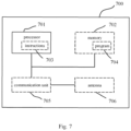
- FIG. 7 shows a schematic structural diagram of a communication device according to an embodiment of the present disclosure.
- a unit or a module represented by a dotted line indicates that the unit or the module is optional.
- the device 700 may be configured to perform the method described in any of the above method embodiments.
- the device 700 may be a terminal device, a network device, or a chip.
- the device 700 includes one or more processors 701.
- the one or more processors 701 may support the device 700 to perform the method according to any of the method embodiments.
- the processor 701 may be a general-purpose processor or a dedicated processor.
- the processor 701 may be a Central Processing Unit (CPU).
- CPU may be configured to control the device 700, execute a software program, and process data of the software program.
- the device 700 may further include a communication unit 705 for implementing signal input (receiving) and output (transmitting).
- the device 700 may be a chip.
- the communication unit 705 may be an input and/or output circuit of the chip.
- the communication unit 705 may be a communication interface of the chip.
- the chip may be embodied as a component of the terminal device or the network device or other wireless communication devices.
- the device 700 may be a terminal device or a network device.
- the communication unit 705 may be a transceiver of the terminal device or the network device.
- the communication unit 705 may be a transceiver circuit of the terminal device or the network device.
- the device 700 may include one or more memories 702 having a program 704 stored thereon.
- the program 704 may be executed by the processor 701 to generate instructions 703, such that the processor 701 performs the method described in any of the above method embodiments in accordance with the instructions 703.
- data may also be stored in the memory 702.
- the processor 701 may also read data stored in the memory 702. The data may be stored either at the same storage address as the program 704, or at a storage address different from that of the program 704.
- the processor 701 and the memory 702 may be arranged separately or integrated together.
- the processor 701 and the memory 702 may be integrated on a System On Chip (SOC) of the terminal device.
- SOC System On Chip
- the device 700 may further include an antenna 706.
- the communication unit 705 may implement a transceiving function of the device 700 through the antenna 706.
- Some or all of the aforementioned different DCIs may be the same DCI.
- some or all of the different PDSCHs as described above e.g. the first PDSCH, the second PDSCH, etc.
- the processor 701 may be a CPU, a Digital Signal Processor (DSP), an Application Specific Integrated Circuit (ASIC), a Field Programmable Gate Array (FPGA), or other programmable logic device, such as a discrete gate, a transistor logic device, or a discrete hardware component.
- DSP Digital Signal Processor
- ASIC Application Specific Integrated Circuit
- FPGA Field Programmable Gate Array
- the present disclosure further provides a computer program product.
- the computer program product when being executed by the processor 701, performs the method according to any method embodiment of the present disclosure.
- the computer program product such as the program 704, may be stored in the memory 702.
- the program 704 is converted into an executable object file that may be executed by the processor 701 after processing processes such as pre-processing, compilation, assembly, and linking.
- the present disclosure further provides a computer-readable storage medium having a computer program stored thereon.
- the computer program when being executed by a computer, performs the method according to any method embodiment of the present disclosure.
- the computer program may be a high-level language program or an executable target program.
- the computer-readable storage medium may be, for example, the memory 702.
- the memory 702 may be a volatile memory or a non-volatile memory. Alternatively, the memory 702 may include both a volatile memory and a non-volatile memory.
- the non-volatile memory may be a Read-Only Memory (ROM), a Programmable ROM (PROM), an Erasable PROM (EPROM), an Electrically EPROM (EEPROM), or a flash memory.
- the volatile memory may be a Random Access Memory (RAM), which may be used as an external cache.
- RAM Direct Rambus RAM
- SRAM Static RAM
- DRAM Dynamic RAM
- SDRAM Synchronous DRAM
- DDR SDRAM Double Data Rate SDRAM
- ESDRAM Enhanced SDRAM
- SLDRAM Synchlink DRAM
- DR RAM Direct Rambus RAM
- the system, apparatus and method disclosed may be implemented in any other ways. For example, some features of the method embodiments described above may be omitted or not executed.
- the apparatus embodiments described above is merely exemplary.
- the divisions of units are only divisions based on logical functions, and there may be other divisions in actual implementations.
- more than one unit or component may be combined or integrated into another system.
- coupling between units or coupling between components may be direct coupling or indirect coupling.
- the above coupling includes electrical, mechanical, or other forms of connection.
- system and “network” are often used interchangeably in embodiments of the present disclosure.
- a and/or B may mean A only, B only, or both A and B.
- symbol “/” as used herein represents an “or” relationship between the relevant objects preceding and succeeding the symbol.
Landscapes
- Engineering & Computer Science (AREA)
- Signal Processing (AREA)
- Computer Networks & Wireless Communication (AREA)
- Quality & Reliability (AREA)
- Mobile Radio Communication Systems (AREA)
Claims (18)
- Kommunikationsverfahren, umfassend:Empfangen (S410) von ersten Konfigurationsinformationen, wobei die ersten Konfigurationsinformationen zum Konfigurieren eines oder mehrerer Steuerressourcensätze, CORESETs, verwendet werden, wobei zumindest einer des einen oder der mehreren CORESETs mit einem jeweiligen Gruppenindex konfiguriert ist und der eine oder die mehreren CORESETs CORESET#0 nicht umfassen;Empfangen (S420), gemäß Planungsinformationen, die auf dem einen oder den mehreren CORESETs und/oder CORESET#0 übertragen werden, eines gemeinsam verwendeten physischen Downlink-Kanals, PDSCH, der durch die Planungsinformationen geplant ist;Empfangen von ersten DCI auf CORESET#0, wobei die ersten DCI zum Planen eines ersten PDSCH ausgelegt sind; undals Reaktion darauf, dass die ersten DCI eine erste vorgegebene Bedingung erfüllen und dass die ersten DCI und der erste PDSCH demselben Komponententräger, CC, entsprechen, Empfangen des ersten PDSCH gemäß einer Quasi-Co-Location-Annahme, QCL-Annahme, eines ersten CORESET,wobei die erste vorgegebene Bedingung angibt, dass ein Zeitintervall zwischen den ersten DCI und dem ersten PDSCH kleiner als eine erste Schwelle ist; undwobei das Verfahren ferner umfasst:Empfangen von zweiten DCI auf CORESET#0, wobei die zweiten DCI zum Planen eines ersten Kanalzustandsinformationen-Referenzsignals, CSI-RS, ausgelegt sind; undals Reaktion darauf, dass die zweiten DCI eine zweite vorgegebene Bedingung erfüllen und dass die zweiten DCI und das erste CSI-RS demselben CC entsprechen, Empfangen des ersten CSI-RS gemäß einem TCI-Zustand oder einer QCL-Annahme eines zweiten CORESET oderals Reaktion darauf, dass die zweiten DCI die zweite vorgegebene Bedingung erfüllen und dass die zweiten DCI und das erste CSI-RS verschiedenen CCs entsprechen, Empfangen des ersten CSI-RS gemäß einem zweiten TCI-Zustand oder einer zweiten QCL-Annahme,wobei die zweite vorgegebene Bedingung angibt, dass ein Zeitintervall zwischen den zweiten DCI und dem ersten CSI-RS kleiner als eine erste Schwelle oder kleiner oder gleich der ersten Schwelle ist.
- Verfahren nach Anspruch 1, wobeider erste CORESET ein CORESET mit dem kleinsten Identifikator, ID, unter Ziel-CORESETs innerhalb des zuletzt detektierten Downlink-Schlitzes auf einem Bandbreitenteil, BWP, entsprechend den ersten DCI ist unddie Ziel-CORESETs CORESETs entsprechend einem ersten Gruppenindex umfassen oder die Ziel-CORESETs die CORESETs entsprechend dem ersten Gruppenindex und/oder CORESET#0 umfassen,wobei der erste Gruppenindex der kleinste Gruppenindex oder der größte Gruppenindex ist oderder erste CORESET einen CORESET mit dem kleinsten ID unter CORESETs innerhalb des zuletzt detektierten Downlink-Schlitzes auf einem jeweiligen BWP umfasst.
- Verfahren nach Anspruch 1, wobeidie erste Schwelle durch eine Endvorrichtung berichtet wird;dass die erste Schwelle durch die Endvorrichtung berichtet wird, bedeutet, dass die erste Schwelle durch die Endvorrichtung durch Parameter von timeDurationForQCL und/oder beamSwitchTiming berichtet wird;die Parameter von timeDurationForQCL und/oder beamSwitchTiming erste Schwellen entsprechend verschiedenen Bändern umfassen oderdie Parameter von timeDurationForQCL und/oder beamSwitchTiming erste Schwellen entsprechend verschiedenen Bandkombinationen umfassen.
- Verfahren nach einem der Ansprüche 1 bis 3, ferner umfassend:
Empfangen von dritten DCI auf CORESET#0, wobei die dritten DCI zum Planen eines zweiten PDSCH ausgelegt sind und eine Verwürfelungs-ID des zweiten PDSCH eine von zumindest einer PDSCH-Verwürfelungs-ID, die durch eine erste RRC-Signalisierung konfiguriert wird, ist. - Verfahren nach einem der Ansprüche 1 bis 4, wobeiHARQ-ACK-Rückkopplungsinformationen entsprechend Daten, die durch DCI geplant sind, die auf CORESET#0 empfangen werden, einem ersten HARQ-ACK-Codebuch entsprechen; unddas erste HARQ-ACK-Codebuch ein HARQ-ACK-Codebuch entsprechend dem kleinsten Gruppenindex ist.
- Verfahren nach einem der Ansprüche 1 bis 5, wobei die Netzwerkvorrichtung die Endvorrichtung zur Verwendung eines semistatischen HARQ-ACK-Codebuchs konfiguriert und HARQ-ACK-Informationsbits in der folgenden Reihenfolge entsprechend verkettet werden durch Vorgänge zum:Indizieren in einer aufsteigenden Reihenfolge über PDSCH-Empfangsereignis-Indizes derselben bedienenden Zelle entsprechend demselben Gruppenindex;Indizieren in einer aufsteigenden Reihenfolge über Indizes einer bedienenden Zelle entsprechend demselben Gruppenindex undIndizieren in einer aufsteigenden Reihenfolge über Gruppenindizes.
- Kommunikationsvorrichtung, umfassend eine Verarbeitungseinheit (610) und eine Empfangseinheit (620), wobei die Verarbeitungseinheit (610) ausgelegt ist zum Steuern der Empfangseinheit (620) zum:Empfangen von ersten Konfigurationsinformationen, wobei die ersten Konfigurationsinformationen zum Konfigurieren eines oder mehrerer Steuerressourcensätze, CORESETs, verwendet werden, wobei zumindest einer des einen oder der mehreren CORESETs mit einem jeweiligen Gruppenindex konfiguriert ist und der eine oder die mehreren CORESETs CORESET#0 nicht umfassen; undEmpfangen, gemäß Planungsinformationen, die auf dem einen oder den mehreren CORESETs und/oder CORESET#0 übertragen werden, eines gemeinsam verwendeten physischen Downlink-Kanals, PDSCH, der durch die Planungsinformationen geplant ist,wobei die Empfangseinheit (620) ferner ausgelegt ist zum:Empfangen von ersten DCI auf CORESET#0, wobei die ersten DCI zum Planen eines ersten PDSCH ausgelegt sind; undals Reaktion darauf, dass die ersten DCI eine erste vorgegebene Bedingung erfüllen und dass die ersten DCI und der erste PDSCH demselben Komponententräger, CC, entsprechen, Empfangen des ersten PDSCH gemäß einer Quasi-Co-Location-Annahme, QCL-Annahme, eines ersten CORESET,wobei die erste vorgegebene Bedingung angibt, dass ein Zeitintervall zwischen den ersten DCI und dem ersten PDSCH kleiner als eine erste Schwelle ist; undwobei die Empfangseinheit (620) ferner ausgelegt ist zum:Empfangen von zweiten DCI auf CORESET#0, wobei die zweiten DCI zum Planen eines ersten Kanalzustandsinformationen-Referenzsignals, CSI-RS, ausgelegt sind; undals Reaktion darauf, dass die zweiten DCI eine zweite vorgegebene Bedingung erfüllen und dass die zweiten DCI und das erste CSI-RS demselben CC entsprechen, Empfangen des ersten CSI-RS gemäß einem TCI-Zustand oder einer QCL-Annahme eines zweiten CORESET oderals Reaktion darauf, dass die zweiten DCI die zweite vorgegebene Bedingung erfüllen und dass die zweiten DCI und das erste CSI-RS verschiedenen CCs entsprechen, Empfangen des ersten CSI-RS gemäß einem zweiten TCI-Zustand oder einer zweiten QCL-Annahme,wobei die zweite vorgegebene Bedingung angibt, dass ein Zeitintervall zwischen den zweiten DCI und dem ersten CSI-RS kleiner als eine erste Schwelle oder kleiner oder gleich der ersten Schwelle ist.
- Vorrichtung nach Anspruch 7, wobeider erste CORESET ein CORESET mit dem kleinsten Identifikator, ID, unter Ziel-CORESETs innerhalb des zuletzt detektierten Downlink-Schlitzes auf einem Bandbreitenteil, BWP, entsprechend den ersten DCI ist unddie Ziel-CORESETs CORESETs entsprechend einem ersten Gruppenindex umfassen oder die Ziel-CORESETs die CORESETs entsprechend dem ersten Gruppenindex und/oder CORESET#0 umfassen,wobei der erste Gruppenindex der kleinste Gruppenindex oder der größte Gruppenindex ist oderder erste CORESET einen CORESET mit dem kleinsten ID unter CORESETs innerhalb des zuletzt detektierten Downlink-Schlitzes auf einem jeweiligen BWP umfasst.
- Vorrichtung nach Anspruch 7, wobeider zweite CORESET ein CORESET mit dem kleinsten ID unter Ziel-CORESETs innerhalb des zuletzt detektierten Downlink-Schlitzes auf einem BWP entsprechend den zweiten DCI ist unddie Ziel-CORESETs CORESETs entsprechend einem zweiten Gruppenindex umfassen oder die Ziel-CORESETs die CORESETs entsprechend dem zweiten Gruppenindex und CORESET#0 umfassen,wobei der zweite Gruppenindex der kleinste Gruppenindex oder der größte Gruppenindex ist oderder zweite CORESET ein CORESET mit dem kleinsten ID unter CORESETs innerhalb des zuletzt detektierten Downlink-Schlitzes auf einem jeweiligen BWP ist.
- Vorrichtung nach Anspruch 7, wobeidie erste Schwelle durch eine Endvorrichtung berichtet wird;dass die erste Schwelle durch die Endvorrichtung berichtet wird, bedeutet, dass die erste Schwelle durch die Endvorrichtung durch Parameter von timeDurationForQCL und/oder beamSwitchTiming berichtet wird;die Parameter von timeDurationForQCL und/oder beamSwitchTiming erste Schwellen entsprechend verschiedenen Bändern umfassen oderdie Parameter von timeDurationForQCL und/oder beamSwitchTiming erste Schwellen entsprechend verschiedenen Bandkombinationen umfassen.
- Vorrichtung nach einem der Ansprüche 7 bis 10, wobei die Empfangseinheit (620) ferner ausgelegt ist zum:
Empfangen von dritten DCI auf CORESET#0, wobei die dritten DCI zum Planen eines zweiten PDSCH ausgelegt sind und eine Verwürfelungs-ID des zweiten PDSCH eine von zumindest einer PDSCH-Verwürfelungs-ID, die durch eine erste RRC-Signalisierung konfiguriert wird, ist. - Vorrichtung nach Anspruch 11, wobeidie erste RRC-Signalisierung dataScramblingldentityPDSCH und/oder AddtionalDataScramblingldentityPDSCH ist unddie dritten DCI in einem DCI-Format 1-1 sind oderdie dritten DCI in einem DCI-Format 1-0 sind, das in einem benutzerausrüstungsspezifischen, UEspezifischen, Suchraum übertragen wird.
- Vorrichtung nach einem der Ansprüche 7 bis 12, wobei die Empfangseinheit (620) ferner ausgelegt ist zum:Empfangen von sechsten DCI auf CORESET#0, wobei die sechsten DCI zum Planen eines dritten PDSCH ausgelegt sind; undals Reaktion auf den Empfang des dritten PDSCH, Durchführen einer Ratenanpassung gemäß einem ersten Zellreferenzsignalmustersatz, CRS-Mustersatz.
- Vorrichtung nach Anspruch 13, wobeider erste CRS-Mustersatz zumindest ein CRS-Muster entsprechend dem kleinsten Gruppenindex umfasst oderder erste CRS-Mustersatz alle CRS-Muster entsprechend einem aktuellen BWP umfasst.
- Vorrichtung nach einem der Ansprüche 7 bis 14, wobeiHARQ-ACK-Rückkopplungsinformationen entsprechend Daten, die durch DCI geplant sind, die auf CORESET#0 empfangen werden, einem ersten HARQ-ACK-Codebuch entsprechen; unddas erste HARQ-ACK-Codebuch ein HARQ-ACK-Codebuch entsprechend dem kleinsten Gruppenindex ist.
- Vorrichtung nach einem der Ansprüche 7 bis 15, wobei die Netzwerkvorrichtung die Endvorrichtung zur Verwendung eines semistatischen HARQ-ACK-Codebuchs konfiguriert und HARQ-ACK-Informationsbits in der folgenden Reihenfolge entsprechend verkettet werden durch Vorgänge zum:Indizieren in einer aufsteigenden Reihenfolge über PDSCH-Empfangsereignis-Indizes derselben bedienenden Zelle entsprechend demselben Gruppenindex;Indizieren in einer aufsteigenden Reihenfolge über Indizes einer bedienenden Zelle entsprechend demselben Gruppenindex undIndizieren in einer aufsteigenden Reihenfolge über Gruppenindizes.
- Vorrichtung nach einem der Ansprüche 7 bis 16,
wobei die Netzwerkvorrichtung die Endvorrichtung zur Verwendung eines dynamischen HARQ-ACK-Codebuchs konfiguriert und die Empfangseinheit ferner ausgelegt ist zum:Bestimmen einer Ressource eines physischen Uplink-Steuerkanals, PUCCH-Ressource, gemäß siebten DCI; undwobei die siebten DCI die letzten DCI unter DCIs sind, die in der folgenden Reihenfolge angeordnet sind durch Vorgänge zum:Indizieren in einer aufsteigenden Reihenfolge über Gruppenindizes entsprechend den DCIs im selben PDCCH-Überwachungsereignis derselben bedienenden Zelle;Indizieren in einer aufsteigenden Reihenfolge über Indizes einer bedienenden Zelle im selben PDCCH-Überwachungsereignis undIndizieren in einer aufsteigenden Reihenfolge über PDCCH-Überwachungsereignis-Indizes. - Vorrichtung nach einem der Ansprüche 16 bis 17, wobei das Indizieren in einer aufsteigenden Reihenfolge über die Gruppenindizes durchgeführt wird und der kleinste Gruppenindex zum Indizieren eines PDSCH, der durch DCI auf CORESET#0 geplant ist, verwendet wird.
Applications Claiming Priority (1)
| Application Number | Priority Date | Filing Date | Title |
|---|---|---|---|
| PCT/CN2019/116826 WO2021088039A1 (zh) | 2019-11-08 | 2019-11-08 | 通信方法和通信装置 |
Publications (3)
| Publication Number | Publication Date |
|---|---|
| EP4044737A1 EP4044737A1 (de) | 2022-08-17 |
| EP4044737A4 EP4044737A4 (de) | 2022-10-26 |
| EP4044737B1 true EP4044737B1 (de) | 2024-08-21 |
Family
ID=75849504
Family Applications (1)
| Application Number | Title | Priority Date | Filing Date |
|---|---|---|---|
| EP19951921.6A Active EP4044737B1 (de) | 2019-11-08 | 2019-11-08 | Kommunikationsverfahren und kommunikationsvorrichtung |
Country Status (4)
| Country | Link |
|---|---|
| US (1) | US12342339B2 (de) |
| EP (1) | EP4044737B1 (de) |
| CN (2) | CN114710840B (de) |
| WO (1) | WO2021088039A1 (de) |
Families Citing this family (10)
| Publication number | Priority date | Publication date | Assignee | Title |
|---|---|---|---|---|
| EP3651525B1 (de) * | 2018-08-03 | 2021-11-24 | LG Electronics Inc. | Verfahren zum konfigurieren eines referenzpunktes unabhängig von einem gemeinsamen ressourcenblockraster und vorrichtung dafür |
| CN110535609B (zh) * | 2019-08-02 | 2023-11-24 | 中兴通讯股份有限公司 | 目标参数的确定方法、通信节点和存储介质 |
| WO2021187903A1 (ko) * | 2020-03-20 | 2021-09-23 | 엘지전자 주식회사 | 무선 통신 시스템에서 공간 파라미터 기반 신호 송수신 방법 및 장치 |
| US11991621B2 (en) * | 2020-10-13 | 2024-05-21 | Ofinno, Llc | Beam update for control resource sets |
| US12309797B2 (en) * | 2021-04-05 | 2025-05-20 | Ofinno, Llc | Requesting feedback information in multi-downlink scheduling |
| CN115567173A (zh) * | 2021-07-02 | 2023-01-03 | 维沃移动通信有限公司 | 信息确定方法、装置及终端 |
| US11985597B2 (en) | 2021-08-05 | 2024-05-14 | Qualcomm Incorporated | Techniques for aperiodic discontinuous reception mode communications |
| US12041000B2 (en) * | 2021-08-05 | 2024-07-16 | Qualcomm Incorporated | Techniques for communicating data channel transmissions |
| US12348452B2 (en) * | 2022-04-04 | 2025-07-01 | Qualcomm Incorporated | Patterns for control channel puncturing and shared channel rate-matching |
| GB2623074A (en) * | 2022-10-03 | 2024-04-10 | Nokia Technologies Oy | Control resource set for enhanced reduced capability user equipment |
Citations (3)
| Publication number | Priority date | Publication date | Assignee | Title |
|---|---|---|---|---|
| US20190174466A1 (en) * | 2018-01-22 | 2019-06-06 | Intel Corporation | Control signaling for uplink multiple input multiple output, channel state information reference signal configuration and sounding reference signal configuration |
| CN110391890A (zh) * | 2018-04-16 | 2019-10-29 | 中兴通讯股份有限公司 | 一种确定准共址参考信号集合的方法和装置 |
| US20190342907A1 (en) * | 2018-05-04 | 2019-11-07 | Asustek Computer Inc. | Method and apparatus for downlink control information (dci) content processing considering active downlink (dl) bandwidth part (bwp) change in a wireless communication system |
Family Cites Families (9)
| Publication number | Priority date | Publication date | Assignee | Title |
|---|---|---|---|---|
| WO2018228487A1 (en) * | 2017-06-15 | 2018-12-20 | Huawei Technologies Co., Ltd. | Method and devices for multiple transmit receive point cooperation for reliable communication |
| CN110366250B (zh) * | 2018-03-26 | 2023-05-12 | 华硕电脑股份有限公司 | 考虑跨载波调度缓存下行链路数据的方法和设备 |
| CN115209548B (zh) * | 2018-04-04 | 2025-12-12 | 维沃移动通信有限公司 | 信道传输方法、终端及网络设备 |
| US11452105B2 (en) * | 2018-04-06 | 2022-09-20 | Nokia Technologies Oy | HARQ-ACK codebook supporting UEs with parallel PDSCH reception capability |
| CN118713804A (zh) * | 2018-04-16 | 2024-09-27 | 中兴通讯股份有限公司 | 一种准共址参考信号的获取方法、装置、设备及存储介质 |
| US11711192B2 (en) * | 2019-07-11 | 2023-07-25 | Samsung Electronics Co., Ltd. | Transmission of control information for communication with multiple transmission-reception points |
| EP4510493A3 (de) * | 2019-08-20 | 2025-04-23 | Samsung Electronics Co., Ltd. | Verfahren und vorrichtung zur anzeige des strahlausfallwiederherstellungsbetriebs eines endgeräts in einem drahtloskommunikationssystem |
| WO2021062709A1 (zh) * | 2019-09-30 | 2021-04-08 | 华为技术有限公司 | 数据传输的方法和装置 |
| US12261802B2 (en) * | 2019-10-04 | 2025-03-25 | Lg Electronics Inc. | Method for transmitting/receiving PDSCH in wireless communication system, and device therefor |
-
2019
- 2019-11-08 EP EP19951921.6A patent/EP4044737B1/de active Active
- 2019-11-08 WO PCT/CN2019/116826 patent/WO2021088039A1/zh not_active Ceased
- 2019-11-08 CN CN202210335530.6A patent/CN114710840B/zh active Active
- 2019-11-08 CN CN201980097815.7A patent/CN114009131A/zh active Pending
-
2022
- 2022-04-27 US US17/731,150 patent/US12342339B2/en active Active
Patent Citations (4)
| Publication number | Priority date | Publication date | Assignee | Title |
|---|---|---|---|---|
| US20190174466A1 (en) * | 2018-01-22 | 2019-06-06 | Intel Corporation | Control signaling for uplink multiple input multiple output, channel state information reference signal configuration and sounding reference signal configuration |
| CN110391890A (zh) * | 2018-04-16 | 2019-10-29 | 中兴通讯股份有限公司 | 一种确定准共址参考信号集合的方法和装置 |
| US20210044403A1 (en) * | 2018-04-16 | 2021-02-11 | Zte Corporation | Method and device for determining quasi co-located reference signal set |
| US20190342907A1 (en) * | 2018-05-04 | 2019-11-07 | Asustek Computer Inc. | Method and apparatus for downlink control information (dci) content processing considering active downlink (dl) bandwidth part (bwp) change in a wireless communication system |
Non-Patent Citations (5)
| Title |
|---|
| INTEL CORPORATION: "CR to 38.214 for CSI-RS (TRS, CSI, IM) + PDSCH multiplexing", vol. RAN WG1, no. Spokane, USA; 20181112 - 20181116, 11 November 2018 (2018-11-11), XP051554407, Retrieved from the Internet <URL:http://www.3gpp.org/ftp/Meetings%5F3GPP%5FSYNC/RAN1/Docs/R1%2D1812469%2Ezip> [retrieved on 20181111] * |
| NTT DOCOMO ET AL: "Offline summary for PDCCH structure and search space", vol. RAN WG1, no. Gothenburg, Sweden; 20180820 - 20180824, 21 August 2018 (2018-08-21), XP051517127, Retrieved from the Internet <URL:http://www.3gpp.org/ftp/tsg%5Fran/WG1%5FRL1/TSGR1%5F94/Docs/R1%2D1809766%2Ezip> [retrieved on 20180821] * |
| QUALCOMM INCORPORATED: "Multi-TRP Enhancements", vol. RAN WG1, no. Prague, Czech Republic; 20190826 - 20190830, 17 August 2019 (2019-08-17), pages 1 - 32, XP051765877, Retrieved from the Internet <URL:http://www.3gpp.org/ftp/tsg_ran/WG1_RL1/TSGR1_98/Docs/R1-1909272.zip> [retrieved on 20190817] * |
| vol. RAN WG1, no. ; 20180401, 7 June 2018 (2018-06-07), XP051455919, Retrieved from the Internet <URL:http://www.3gpp.org/ftp/Meetings%5F3GPP%5FSYNC/RAN/Docs> [retrieved on 20180607] * |
| ZTE: "Enhancements on Multi-TRP and Multi-panel Transmission", vol. RAN WG1, no. Chongqing, China; 20191014 - 20191020, 5 October 2019 (2019-10-05), XP051789089, Retrieved from the Internet <URL:http://www.3gpp.org/ftp/tsg_ran/WG1_RL1/TSGR1_98b/Docs/R1-1910284.zip> [retrieved on 20191005] * |
Also Published As
| Publication number | Publication date |
|---|---|
| CN114710840B (zh) | 2023-09-22 |
| CN114009131A (zh) | 2022-02-01 |
| EP4044737A1 (de) | 2022-08-17 |
| CN114710840A (zh) | 2022-07-05 |
| US20220256574A1 (en) | 2022-08-11 |
| WO2021088039A1 (zh) | 2021-05-14 |
| US12342339B2 (en) | 2025-06-24 |
| EP4044737A4 (de) | 2022-10-26 |
Similar Documents
| Publication | Publication Date | Title |
|---|---|---|
| EP4044737B1 (de) | Kommunikationsverfahren und kommunikationsvorrichtung | |
| US11737111B2 (en) | Method and apparatus for communicating user data via a physical shared channel | |
| US11569949B2 (en) | Communication method and communications apparatus | |
| US12309791B2 (en) | Method and device for transmitting uplink signal | |
| US12089223B2 (en) | Signal reception or transmission method and apparatus and system | |
| US12470351B2 (en) | Sidelink information transmission method and terminal device | |
| EP3731446A1 (de) | Verfahren zur übertragung von uplink-daten und endgerätevorrichtung | |
| EP3833129A1 (de) | Verfahren zur übertragung von konfigurationsinformationen und endgerätevorrichtung | |
| US11296855B2 (en) | Communication method, terminal device, and network device | |
| JP7347668B2 (ja) | 無線通信方法、装置及びシステム | |
| CN113490278B (zh) | 下行信号传输的方法和设备 | |
| US20220393717A1 (en) | Flexible frequency hopping | |
| WO2022077478A1 (zh) | 一种基于波束的通信方法以及相关装置 | |
| US20260025302A1 (en) | Signal transmission/reception method for wireless communication, and device therefor | |
| CN116326058A (zh) | 一种数据传输方法和装置 | |
| WO2023050260A1 (zh) | 无线通信方法和设备 | |
| EP4572258A1 (de) | Verfahren und vorrichtung zur meldung von kanalstatusinformationen | |
| CN107113814A (zh) | 无线通信的方法、网络设备和终端设备 | |
| WO2023010426A1 (en) | Methods and systems for coverage enhancement in wireless networks | |
| WO2021093646A1 (en) | Method and apparatus of signal processing for pt-rs transmission in multi-trp system | |
| CN119653506A (zh) | 通信方法、装置、设备、存储介质、芯片、产品及程序 | |
| US20250089069A1 (en) | Data transmission method and apparatus, and terminal device and network device | |
| WO2025065596A1 (en) | Beam collision handling for multiple-transmission-and-reception-point systems | |
| US20250158783A1 (en) | Signal reception method, signal transmission method and apparatus | |
| CN119893583A (zh) | 侧行链路上信息传输的方法和通信装置 |
Legal Events
| Date | Code | Title | Description |
|---|---|---|---|
| STAA | Information on the status of an ep patent application or granted ep patent |
Free format text: STATUS: THE INTERNATIONAL PUBLICATION HAS BEEN MADE |
|
| PUAI | Public reference made under article 153(3) epc to a published international application that has entered the european phase |
Free format text: ORIGINAL CODE: 0009012 |
|
| STAA | Information on the status of an ep patent application or granted ep patent |
Free format text: STATUS: REQUEST FOR EXAMINATION WAS MADE |
|
| 17P | Request for examination filed |
Effective date: 20220509 |
|
| AK | Designated contracting states |
Kind code of ref document: A1 Designated state(s): AL AT BE BG CH CY CZ DE DK EE ES FI FR GB GR HR HU IE IS IT LI LT LU LV MC MK MT NL NO PL PT RO RS SE SI SK SM TR |
|
| A4 | Supplementary search report drawn up and despatched |
Effective date: 20220927 |
|
| RIC1 | Information provided on ipc code assigned before grant |
Ipc: H04W 72/12 20090101AFI20220921BHEP |
|
| DAV | Request for validation of the european patent (deleted) | ||
| DAX | Request for extension of the european patent (deleted) | ||
| STAA | Information on the status of an ep patent application or granted ep patent |
Free format text: STATUS: EXAMINATION IS IN PROGRESS |
|
| 17Q | First examination report despatched |
Effective date: 20230712 |
|
| REG | Reference to a national code |
Ref country code: DE Ref legal event code: R079 Free format text: PREVIOUS MAIN CLASS: H04W0072120000 Ipc: H04L0005000000 Ref document number: 602019057699 Country of ref document: DE |
|
| RIC1 | Information provided on ipc code assigned before grant |
Ipc: H04W 72/12 20090101ALI20240220BHEP Ipc: H04L 1/1607 20230101ALI20240220BHEP Ipc: H04L 5/00 20060101AFI20240220BHEP |
|
| GRAP | Despatch of communication of intention to grant a patent |
Free format text: ORIGINAL CODE: EPIDOSNIGR1 |
|
| STAA | Information on the status of an ep patent application or granted ep patent |
Free format text: STATUS: GRANT OF PATENT IS INTENDED |
|
| INTG | Intention to grant announced |
Effective date: 20240404 |
|
| GRAS | Grant fee paid |
Free format text: ORIGINAL CODE: EPIDOSNIGR3 |
|
| GRAA | (expected) grant |
Free format text: ORIGINAL CODE: 0009210 |
|
| STAA | Information on the status of an ep patent application or granted ep patent |
Free format text: STATUS: THE PATENT HAS BEEN GRANTED |
|
| AK | Designated contracting states |
Kind code of ref document: B1 Designated state(s): AL AT BE BG CH CY CZ DE DK EE ES FI FR GB GR HR HU IE IS IT LI LT LU LV MC MK MT NL NO PL PT RO RS SE SI SK SM TR |
|
| REG | Reference to a national code |
Ref country code: GB Ref legal event code: FG4D |
|
| REG | Reference to a national code |
Ref country code: CH Ref legal event code: EP |
|
| REG | Reference to a national code |
Ref country code: IE Ref legal event code: FG4D |
|
| REG | Reference to a national code |
Ref country code: DE Ref legal event code: R096 Ref document number: 602019057699 Country of ref document: DE |
|
| P01 | Opt-out of the competence of the unified patent court (upc) registered |
Free format text: CASE NUMBER: APP_49588/2024 Effective date: 20240902 |
|
| REG | Reference to a national code |
Ref country code: LT Ref legal event code: MG9D |
|
| REG | Reference to a national code |
Ref country code: NL Ref legal event code: MP Effective date: 20240821 |
|
| PG25 | Lapsed in a contracting state [announced via postgrant information from national office to epo] |
Ref country code: NO Free format text: LAPSE BECAUSE OF FAILURE TO SUBMIT A TRANSLATION OF THE DESCRIPTION OR TO PAY THE FEE WITHIN THE PRESCRIBED TIME-LIMIT Effective date: 20241121 |
|
| REG | Reference to a national code |
Ref country code: AT Ref legal event code: MK05 Ref document number: 1716583 Country of ref document: AT Kind code of ref document: T Effective date: 20240821 |
|
| PG25 | Lapsed in a contracting state [announced via postgrant information from national office to epo] |
Ref country code: NL Free format text: LAPSE BECAUSE OF FAILURE TO SUBMIT A TRANSLATION OF THE DESCRIPTION OR TO PAY THE FEE WITHIN THE PRESCRIBED TIME-LIMIT Effective date: 20240821 Ref country code: PL Free format text: LAPSE BECAUSE OF FAILURE TO SUBMIT A TRANSLATION OF THE DESCRIPTION OR TO PAY THE FEE WITHIN THE PRESCRIBED TIME-LIMIT Effective date: 20240821 Ref country code: PT Free format text: LAPSE BECAUSE OF FAILURE TO SUBMIT A TRANSLATION OF THE DESCRIPTION OR TO PAY THE FEE WITHIN THE PRESCRIBED TIME-LIMIT Effective date: 20241223 Ref country code: FI Free format text: LAPSE BECAUSE OF FAILURE TO SUBMIT A TRANSLATION OF THE DESCRIPTION OR TO PAY THE FEE WITHIN THE PRESCRIBED TIME-LIMIT Effective date: 20240821 Ref country code: GR Free format text: LAPSE BECAUSE OF FAILURE TO SUBMIT A TRANSLATION OF THE DESCRIPTION OR TO PAY THE FEE WITHIN THE PRESCRIBED TIME-LIMIT Effective date: 20241122 |
|
| PG25 | Lapsed in a contracting state [announced via postgrant information from national office to epo] |
Ref country code: BG Free format text: LAPSE BECAUSE OF FAILURE TO SUBMIT A TRANSLATION OF THE DESCRIPTION OR TO PAY THE FEE WITHIN THE PRESCRIBED TIME-LIMIT Effective date: 20240821 |
|
| PG25 | Lapsed in a contracting state [announced via postgrant information from national office to epo] |
Ref country code: LV Free format text: LAPSE BECAUSE OF FAILURE TO SUBMIT A TRANSLATION OF THE DESCRIPTION OR TO PAY THE FEE WITHIN THE PRESCRIBED TIME-LIMIT Effective date: 20240821 |
|
| PG25 | Lapsed in a contracting state [announced via postgrant information from national office to epo] |
Ref country code: AT Free format text: LAPSE BECAUSE OF FAILURE TO SUBMIT A TRANSLATION OF THE DESCRIPTION OR TO PAY THE FEE WITHIN THE PRESCRIBED TIME-LIMIT Effective date: 20240821 Ref country code: IS Free format text: LAPSE BECAUSE OF FAILURE TO SUBMIT A TRANSLATION OF THE DESCRIPTION OR TO PAY THE FEE WITHIN THE PRESCRIBED TIME-LIMIT Effective date: 20241221 |
|
| PG25 | Lapsed in a contracting state [announced via postgrant information from national office to epo] |
Ref country code: HR Free format text: LAPSE BECAUSE OF FAILURE TO SUBMIT A TRANSLATION OF THE DESCRIPTION OR TO PAY THE FEE WITHIN THE PRESCRIBED TIME-LIMIT Effective date: 20240821 |
|
| PG25 | Lapsed in a contracting state [announced via postgrant information from national office to epo] |
Ref country code: RS Free format text: LAPSE BECAUSE OF FAILURE TO SUBMIT A TRANSLATION OF THE DESCRIPTION OR TO PAY THE FEE WITHIN THE PRESCRIBED TIME-LIMIT Effective date: 20241121 Ref country code: ES Free format text: LAPSE BECAUSE OF FAILURE TO SUBMIT A TRANSLATION OF THE DESCRIPTION OR TO PAY THE FEE WITHIN THE PRESCRIBED TIME-LIMIT Effective date: 20240821 |
|
| PG25 | Lapsed in a contracting state [announced via postgrant information from national office to epo] |
Ref country code: RS Free format text: LAPSE BECAUSE OF FAILURE TO SUBMIT A TRANSLATION OF THE DESCRIPTION OR TO PAY THE FEE WITHIN THE PRESCRIBED TIME-LIMIT Effective date: 20241121 Ref country code: PT Free format text: LAPSE BECAUSE OF FAILURE TO SUBMIT A TRANSLATION OF THE DESCRIPTION OR TO PAY THE FEE WITHIN THE PRESCRIBED TIME-LIMIT Effective date: 20241223 Ref country code: PL Free format text: LAPSE BECAUSE OF FAILURE TO SUBMIT A TRANSLATION OF THE DESCRIPTION OR TO PAY THE FEE WITHIN THE PRESCRIBED TIME-LIMIT Effective date: 20240821 Ref country code: NO Free format text: LAPSE BECAUSE OF FAILURE TO SUBMIT A TRANSLATION OF THE DESCRIPTION OR TO PAY THE FEE WITHIN THE PRESCRIBED TIME-LIMIT Effective date: 20241121 Ref country code: NL Free format text: LAPSE BECAUSE OF FAILURE TO SUBMIT A TRANSLATION OF THE DESCRIPTION OR TO PAY THE FEE WITHIN THE PRESCRIBED TIME-LIMIT Effective date: 20240821 Ref country code: LV Free format text: LAPSE BECAUSE OF FAILURE TO SUBMIT A TRANSLATION OF THE DESCRIPTION OR TO PAY THE FEE WITHIN THE PRESCRIBED TIME-LIMIT Effective date: 20240821 Ref country code: IS Free format text: LAPSE BECAUSE OF FAILURE TO SUBMIT A TRANSLATION OF THE DESCRIPTION OR TO PAY THE FEE WITHIN THE PRESCRIBED TIME-LIMIT Effective date: 20241221 Ref country code: HR Free format text: LAPSE BECAUSE OF FAILURE TO SUBMIT A TRANSLATION OF THE DESCRIPTION OR TO PAY THE FEE WITHIN THE PRESCRIBED TIME-LIMIT Effective date: 20240821 Ref country code: GR Free format text: LAPSE BECAUSE OF FAILURE TO SUBMIT A TRANSLATION OF THE DESCRIPTION OR TO PAY THE FEE WITHIN THE PRESCRIBED TIME-LIMIT Effective date: 20241122 Ref country code: FI Free format text: LAPSE BECAUSE OF FAILURE TO SUBMIT A TRANSLATION OF THE DESCRIPTION OR TO PAY THE FEE WITHIN THE PRESCRIBED TIME-LIMIT Effective date: 20240821 Ref country code: ES Free format text: LAPSE BECAUSE OF FAILURE TO SUBMIT A TRANSLATION OF THE DESCRIPTION OR TO PAY THE FEE WITHIN THE PRESCRIBED TIME-LIMIT Effective date: 20240821 Ref country code: BG Free format text: LAPSE BECAUSE OF FAILURE TO SUBMIT A TRANSLATION OF THE DESCRIPTION OR TO PAY THE FEE WITHIN THE PRESCRIBED TIME-LIMIT Effective date: 20240821 Ref country code: AT Free format text: LAPSE BECAUSE OF FAILURE TO SUBMIT A TRANSLATION OF THE DESCRIPTION OR TO PAY THE FEE WITHIN THE PRESCRIBED TIME-LIMIT Effective date: 20240821 |
|
| PG25 | Lapsed in a contracting state [announced via postgrant information from national office to epo] |
Ref country code: DK Free format text: LAPSE BECAUSE OF FAILURE TO SUBMIT A TRANSLATION OF THE DESCRIPTION OR TO PAY THE FEE WITHIN THE PRESCRIBED TIME-LIMIT Effective date: 20240821 Ref country code: RO Free format text: LAPSE BECAUSE OF FAILURE TO SUBMIT A TRANSLATION OF THE DESCRIPTION OR TO PAY THE FEE WITHIN THE PRESCRIBED TIME-LIMIT Effective date: 20240821 Ref country code: SM Free format text: LAPSE BECAUSE OF FAILURE TO SUBMIT A TRANSLATION OF THE DESCRIPTION OR TO PAY THE FEE WITHIN THE PRESCRIBED TIME-LIMIT Effective date: 20240821 |
|
| PG25 | Lapsed in a contracting state [announced via postgrant information from national office to epo] |
Ref country code: EE Free format text: LAPSE BECAUSE OF FAILURE TO SUBMIT A TRANSLATION OF THE DESCRIPTION OR TO PAY THE FEE WITHIN THE PRESCRIBED TIME-LIMIT Effective date: 20240821 |
|
| PG25 | Lapsed in a contracting state [announced via postgrant information from national office to epo] |
Ref country code: CZ Free format text: LAPSE BECAUSE OF FAILURE TO SUBMIT A TRANSLATION OF THE DESCRIPTION OR TO PAY THE FEE WITHIN THE PRESCRIBED TIME-LIMIT Effective date: 20240821 |
|
| PG25 | Lapsed in a contracting state [announced via postgrant information from national office to epo] |
Ref country code: SK Free format text: LAPSE BECAUSE OF FAILURE TO SUBMIT A TRANSLATION OF THE DESCRIPTION OR TO PAY THE FEE WITHIN THE PRESCRIBED TIME-LIMIT Effective date: 20240821 Ref country code: IT Free format text: LAPSE BECAUSE OF FAILURE TO SUBMIT A TRANSLATION OF THE DESCRIPTION OR TO PAY THE FEE WITHIN THE PRESCRIBED TIME-LIMIT Effective date: 20240821 |
|
| REG | Reference to a national code |
Ref country code: DE Ref legal event code: R097 Ref document number: 602019057699 Country of ref document: DE |
|
| PLBE | No opposition filed within time limit |
Free format text: ORIGINAL CODE: 0009261 |
|
| STAA | Information on the status of an ep patent application or granted ep patent |
Free format text: STATUS: NO OPPOSITION FILED WITHIN TIME LIMIT |
|
| REG | Reference to a national code |
Ref country code: CH Ref legal event code: PL |
|
| PG25 | Lapsed in a contracting state [announced via postgrant information from national office to epo] |
Ref country code: MC Free format text: LAPSE BECAUSE OF FAILURE TO SUBMIT A TRANSLATION OF THE DESCRIPTION OR TO PAY THE FEE WITHIN THE PRESCRIBED TIME-LIMIT Effective date: 20240821 |
|
| PG25 | Lapsed in a contracting state [announced via postgrant information from national office to epo] |
Ref country code: LU Free format text: LAPSE BECAUSE OF NON-PAYMENT OF DUE FEES Effective date: 20241108 |
|
| REG | Reference to a national code |
Ref country code: CH Ref legal event code: PL |
|
| PG25 | Lapsed in a contracting state [announced via postgrant information from national office to epo] |
Ref country code: CH Free format text: LAPSE BECAUSE OF NON-PAYMENT OF DUE FEES Effective date: 20241130 |
|
| 26N | No opposition filed |
Effective date: 20250522 |
|
| REG | Reference to a national code |
Ref country code: BE Ref legal event code: MM Effective date: 20241130 |
|
| PG25 | Lapsed in a contracting state [announced via postgrant information from national office to epo] |
Ref country code: SE Free format text: LAPSE BECAUSE OF FAILURE TO SUBMIT A TRANSLATION OF THE DESCRIPTION OR TO PAY THE FEE WITHIN THE PRESCRIBED TIME-LIMIT Effective date: 20240821 |
|
| PG25 | Lapsed in a contracting state [announced via postgrant information from national office to epo] |
Ref country code: BE Free format text: LAPSE BECAUSE OF NON-PAYMENT OF DUE FEES Effective date: 20241130 |
|
| PG25 | Lapsed in a contracting state [announced via postgrant information from national office to epo] |
Ref country code: IE Free format text: LAPSE BECAUSE OF NON-PAYMENT OF DUE FEES Effective date: 20241108 |
|
| PGFP | Annual fee paid to national office [announced via postgrant information from national office to epo] |
Ref country code: DE Payment date: 20251124 Year of fee payment: 7 |
|
| PGFP | Annual fee paid to national office [announced via postgrant information from national office to epo] |
Ref country code: GB Payment date: 20251126 Year of fee payment: 7 |
|
| PGFP | Annual fee paid to national office [announced via postgrant information from national office to epo] |
Ref country code: FR Payment date: 20251126 Year of fee payment: 7 |
|
| PG25 | Lapsed in a contracting state [announced via postgrant information from national office to epo] |
Ref country code: HU Free format text: LAPSE BECAUSE OF FAILURE TO SUBMIT A TRANSLATION OF THE DESCRIPTION OR TO PAY THE FEE WITHIN THE PRESCRIBED TIME-LIMIT; INVALID AB INITIO Effective date: 20191108 |