EP4044467A1 - Verfahren und vorrichtung zum bereitstellen einer zeitquelle für einen automatischen antrieb - Google Patents
Verfahren und vorrichtung zum bereitstellen einer zeitquelle für einen automatischen antrieb Download PDFInfo
- Publication number
- EP4044467A1 EP4044467A1 EP19953177.3A EP19953177A EP4044467A1 EP 4044467 A1 EP4044467 A1 EP 4044467A1 EP 19953177 A EP19953177 A EP 19953177A EP 4044467 A1 EP4044467 A1 EP 4044467A1
- Authority
- EP
- European Patent Office
- Prior art keywords
- frequency
- frequency ratio
- time
- time source
- historical
- Prior art date
- Legal status (The legal status is an assumption and is not a legal conclusion. Google has not performed a legal analysis and makes no representation as to the accuracy of the status listed.)
- Pending
Links
- 238000000034 method Methods 0.000 title claims abstract description 90
- 239000013078 crystal Substances 0.000 claims abstract description 109
- 230000008569 process Effects 0.000 claims description 35
- 238000005259 measurement Methods 0.000 claims description 13
- 238000013473 artificial intelligence Methods 0.000 abstract description 4
- 101100113690 Homo sapiens CLK1 gene Proteins 0.000 description 34
- 230000015654 memory Effects 0.000 description 31
- 238000004891 communication Methods 0.000 description 27
- 238000010586 diagram Methods 0.000 description 26
- 238000007726 management method Methods 0.000 description 25
- 230000006870 function Effects 0.000 description 20
- 238000004364 calculation method Methods 0.000 description 10
- 238000005516 engineering process Methods 0.000 description 10
- 238000012550 audit Methods 0.000 description 9
- 230000002093 peripheral effect Effects 0.000 description 9
- 238000012545 processing Methods 0.000 description 8
- 230000005540 biological transmission Effects 0.000 description 7
- 238000012544 monitoring process Methods 0.000 description 7
- 230000005012 migration Effects 0.000 description 6
- 238000013508 migration Methods 0.000 description 6
- 230000010355 oscillation Effects 0.000 description 6
- 230000001360 synchronised effect Effects 0.000 description 6
- 238000001514 detection method Methods 0.000 description 5
- 230000003287 optical effect Effects 0.000 description 5
- 230000002159 abnormal effect Effects 0.000 description 4
- 230000008859 change Effects 0.000 description 4
- 230000009191 jumping Effects 0.000 description 4
- 101100328957 Caenorhabditis elegans clk-1 gene Proteins 0.000 description 3
- 230000009471 action Effects 0.000 description 3
- 230000001413 cellular effect Effects 0.000 description 3
- 230000008878 coupling Effects 0.000 description 3
- 238000010168 coupling process Methods 0.000 description 3
- 238000005859 coupling reaction Methods 0.000 description 3
- 239000000446 fuel Substances 0.000 description 3
- 238000012423 maintenance Methods 0.000 description 3
- 230000006855 networking Effects 0.000 description 3
- 238000013439 planning Methods 0.000 description 3
- 230000003068 static effect Effects 0.000 description 3
- 238000012360 testing method Methods 0.000 description 3
- 238000012384 transportation and delivery Methods 0.000 description 3
- ATUOYWHBWRKTHZ-UHFFFAOYSA-N Propane Chemical compound CCC ATUOYWHBWRKTHZ-UHFFFAOYSA-N 0.000 description 2
- 206010039203 Road traffic accident Diseases 0.000 description 2
- 230000005856 abnormality Effects 0.000 description 2
- 238000002485 combustion reaction Methods 0.000 description 2
- 230000006835 compression Effects 0.000 description 2
- 238000007906 compression Methods 0.000 description 2
- 230000007246 mechanism Effects 0.000 description 2
- 230000000630 rising effect Effects 0.000 description 2
- 238000012546 transfer Methods 0.000 description 2
- LFQSCWFLJHTTHZ-UHFFFAOYSA-N Ethanol Chemical compound CCO LFQSCWFLJHTTHZ-UHFFFAOYSA-N 0.000 description 1
- 101001093748 Homo sapiens Phosphatidylinositol N-acetylglucosaminyltransferase subunit P Proteins 0.000 description 1
- HBBGRARXTFLTSG-UHFFFAOYSA-N Lithium ion Chemical compound [Li+] HBBGRARXTFLTSG-UHFFFAOYSA-N 0.000 description 1
- 241001025261 Neoraja caerulea Species 0.000 description 1
- 230000001133 acceleration Effects 0.000 description 1
- 239000002253 acid Substances 0.000 description 1
- 230000008901 benefit Effects 0.000 description 1
- 230000002457 bidirectional effect Effects 0.000 description 1
- 238000010276 construction Methods 0.000 description 1
- 238000013523 data management Methods 0.000 description 1
- 238000013500 data storage Methods 0.000 description 1
- 238000013461 design Methods 0.000 description 1
- 238000011161 development Methods 0.000 description 1
- 230000002349 favourable effect Effects 0.000 description 1
- 230000004927 fusion Effects 0.000 description 1
- 230000036541 health Effects 0.000 description 1
- 239000012212 insulator Substances 0.000 description 1
- 230000003993 interaction Effects 0.000 description 1
- 229910001416 lithium ion Inorganic materials 0.000 description 1
- 238000012986 modification Methods 0.000 description 1
- 230000004048 modification Effects 0.000 description 1
- 230000008520 organization Effects 0.000 description 1
- 239000003208 petroleum Substances 0.000 description 1
- 239000001294 propane Substances 0.000 description 1
- 239000010453 quartz Substances 0.000 description 1
- 230000008054 signal transmission Effects 0.000 description 1
- VYPSYNLAJGMNEJ-UHFFFAOYSA-N silicon dioxide Inorganic materials O=[Si]=O VYPSYNLAJGMNEJ-UHFFFAOYSA-N 0.000 description 1
- 230000006641 stabilisation Effects 0.000 description 1
- 238000011105 stabilization Methods 0.000 description 1
- 230000001052 transient effect Effects 0.000 description 1
Images


Classifications
-
- H—ELECTRICITY
- H04—ELECTRIC COMMUNICATION TECHNIQUE
- H04B—TRANSMISSION
- H04B7/00—Radio transmission systems, i.e. using radiation field
- H04B7/14—Relay systems
- H04B7/15—Active relay systems
- H04B7/185—Space-based or airborne stations; Stations for satellite systems
- H04B7/1851—Systems using a satellite or space-based relay
- H04B7/18519—Operations control, administration or maintenance
-
- H—ELECTRICITY
- H04—ELECTRIC COMMUNICATION TECHNIQUE
- H04J—MULTIPLEX COMMUNICATION
- H04J3/00—Time-division multiplex systems
- H04J3/02—Details
- H04J3/06—Synchronising arrangements
- H04J3/0635—Clock or time synchronisation in a network
- H04J3/0638—Clock or time synchronisation among nodes; Internode synchronisation
- H04J3/0641—Change of the master or reference, e.g. take-over or failure of the master
-
- B—PERFORMING OPERATIONS; TRANSPORTING
- B60—VEHICLES IN GENERAL
- B60W—CONJOINT CONTROL OF VEHICLE SUB-UNITS OF DIFFERENT TYPE OR DIFFERENT FUNCTION; CONTROL SYSTEMS SPECIALLY ADAPTED FOR HYBRID VEHICLES; ROAD VEHICLE DRIVE CONTROL SYSTEMS FOR PURPOSES NOT RELATED TO THE CONTROL OF A PARTICULAR SUB-UNIT
- B60W60/00—Drive control systems specially adapted for autonomous road vehicles
- B60W60/001—Planning or execution of driving tasks
-
- G—PHYSICS
- G06—COMPUTING; CALCULATING OR COUNTING
- G06F—ELECTRIC DIGITAL DATA PROCESSING
- G06F1/00—Details not covered by groups G06F3/00 - G06F13/00 and G06F21/00
- G06F1/04—Generating or distributing clock signals or signals derived directly therefrom
- G06F1/06—Clock generators producing several clock signals
-
- G—PHYSICS
- G06—COMPUTING; CALCULATING OR COUNTING
- G06F—ELECTRIC DIGITAL DATA PROCESSING
- G06F1/00—Details not covered by groups G06F3/00 - G06F13/00 and G06F21/00
- G06F1/04—Generating or distributing clock signals or signals derived directly therefrom
- G06F1/14—Time supervision arrangements, e.g. real time clock
-
- H—ELECTRICITY
- H04—ELECTRIC COMMUNICATION TECHNIQUE
- H04W—WIRELESS COMMUNICATION NETWORKS
- H04W56/00—Synchronisation arrangements
- H04W56/001—Synchronization between nodes
- H04W56/0015—Synchronization between nodes one node acting as a reference for the others
-
- B—PERFORMING OPERATIONS; TRANSPORTING
- B60—VEHICLES IN GENERAL
- B60W—CONJOINT CONTROL OF VEHICLE SUB-UNITS OF DIFFERENT TYPE OR DIFFERENT FUNCTION; CONTROL SYSTEMS SPECIALLY ADAPTED FOR HYBRID VEHICLES; ROAD VEHICLE DRIVE CONTROL SYSTEMS FOR PURPOSES NOT RELATED TO THE CONTROL OF A PARTICULAR SUB-UNIT
- B60W2556/00—Input parameters relating to data
- B60W2556/45—External transmission of data to or from the vehicle
- B60W2556/50—External transmission of data to or from the vehicle of positioning data, e.g. GPS [Global Positioning System] data
-
- H—ELECTRICITY
- H03—ELECTRONIC CIRCUITRY
- H03B—GENERATION OF OSCILLATIONS, DIRECTLY OR BY FREQUENCY-CHANGING, BY CIRCUITS EMPLOYING ACTIVE ELEMENTS WHICH OPERATE IN A NON-SWITCHING MANNER; GENERATION OF NOISE BY SUCH CIRCUITS
- H03B5/00—Generation of oscillations using amplifier with regenerative feedback from output to input
- H03B5/30—Generation of oscillations using amplifier with regenerative feedback from output to input with frequency-determining element being electromechanical resonator
-
- H—ELECTRICITY
- H04—ELECTRIC COMMUNICATION TECHNIQUE
- H04J—MULTIPLEX COMMUNICATION
- H04J3/00—Time-division multiplex systems
- H04J3/02—Details
- H04J3/06—Synchronising arrangements
- H04J3/0635—Clock or time synchronisation in a network
- H04J3/0638—Clock or time synchronisation among nodes; Internode synchronisation
- H04J3/0644—External master-clock
-
- H—ELECTRICITY
- H04—ELECTRIC COMMUNICATION TECHNIQUE
- H04J—MULTIPLEX COMMUNICATION
- H04J3/00—Time-division multiplex systems
- H04J3/02—Details
- H04J3/06—Synchronising arrangements
- H04J3/0635—Clock or time synchronisation in a network
- H04J3/0638—Clock or time synchronisation among nodes; Internode synchronisation
- H04J3/0658—Clock or time synchronisation among packet nodes
- H04J3/0661—Clock or time synchronisation among packet nodes using timestamps
- H04J3/0667—Bidirectional timestamps, e.g. NTP or PTP for compensation of clock drift and for compensation of propagation delays
Definitions
- This application relates to the field of time synchronization technologies, and in particular, to a method and an apparatus for providing a time source for autonomous driving.
- Artificial intelligence is a theory, a method, a technology, or an application system that simulates, extends, and expands human intelligence by using a digital computer or a machine controlled by the digital computer, to perceive an environment, obtain knowledge, and achieve an optimal result based on the knowledge.
- Autonomous driving is a mainstream application of artificial intelligence.
- Autonomous driving technology depends on collaboration among computer vision, radar, monitoring apparatus, global positioning system, and the like, to implement autonomous driving of a motor vehicle without human operation.
- An autonomous vehicle uses various computing systems to assist in transporting passengers from one location to another. Some autonomous vehicles may require some initial or continuous input from operators (such as navigators, drivers, or passengers).
- Autonomous driving vehicle allows the operator to switch from a manual operation mode to an autonomous driving mode or a mode between the manual operation mode and the autonomous driving mode. Because the autonomous driving technology does not require human to drive the motor vehicle, a human driving failure can be effectively avoided theoretically, a traffic accident can be reduced, and road transportation efficiency can be improved. Therefore, the autonomous driving technology attracts increasing attention.
- an autonomous driving system there are a large quantity of heterogeneous compute nodes related to autonomous driving, for example, various sensors, a central compute node, a microcontroller unit (Microcontroller Unit, MCU) control node, a power management node, and a security monitoring node.
- a microcontroller unit Microcontroller Unit, MCU
- MCU microcontroller Unit
- a power management node Keeping high-precision time synchronization among these nodes is a basic prerequisite for secure and reliable operation of autonomous driving algorithms such as sensing, positioning, and fusion planning and control.
- a coordinated universal time service needs to be provided for another service (for example, a management service) related to the autonomous driving system, to meet real time recording requirements of services such as security audit, maintenance and test logs, and driving data migration to cloud in real time.
- a global navigation satellite system (Global Navigation Satellite System, GNSS) time signal is usually used as a master clock (that is, a grandmaster clock) of the entire system, to provide a time reference for another node.
- GNSS Global Navigation Satellite System
- the GNSS signal When the GNSS signal is unavailable, operation of system time is maintained relying on free oscillation of a crystal oscillator. In a process of tracing the GNSS signal, the GNSS signal may fail to be received, be shielded, or be received incorrectly. In addition, because the GNSS signal is unstable, time jumping often occurs in a driving process of the vehicle, which affects security and reliability of an autonomous driving algorithm, brings a serious potential security risk to the security of autonomous driving, and even leads to a serious traffic accident.
- Embodiments of the present invention provide a method and an apparatus for providing a time source for autonomous driving, to provide a stable and reliable global time source reference for an autonomous driving system, ensure secure operation of the autonomous driving system, and meet a requirement of the system for coordinated universal time.
- an embodiment of the present invention provides an apparatus for providing a time source for autonomous driving, applied to an autonomous driving system of a vehicle, and including: a first processor and a first crystal oscillator connected to the first processor.
- the first processor is configured to provide a first time source for a first subsystem of the autonomous driving system by using the first crystal oscillator, and provide a second time source for a second subsystem of the autonomous driving system based on a received satellite time signal.
- the first subsystem is configured to process driving service-related data of the vehicle
- the second subsystem is configured to process management-related data of the vehicle.
- independent time sources are provided for different subsystems (including the first subsystem and the second subsystem).
- the first time source is used to provide a time source for the first subsystem (for example, a driving service subsystem related to autonomous driving decision-making, control, and sensing), and serve as a master clock of the first subsystem.
- the second time source is configured to provide a time source for the second subsystem (for example, a management subsystem related to security audit, maintenance and test log recording, and driving data migration to cloud), and serve as a master clock of the second subsystem.
- Each of the two independent clock sources operates in a corresponding clock system to provide reference time for another node in the corresponding clock system.
- the first time source after the first time source obtains bootup time, even if a GNSS signal can be received, the first time source maintains accuracy of time in the system only by using the first crystal oscillator (which is referred to as a first crystal oscillator in the following, for example, a board high-precision temperature compensated crystal oscillator) without relying on the GNSS signal.
- the vehicle can receive the satellite time signal (that is, the GNSS signal)
- the second time source traces a GNSS clock provided by a satellite.
- the two independent time sources and the corresponding clock systems are provided, so that the time sources are isolated from each other, operate independently, and do not affect each other.
- a clock (or referred to as a time source) on which the first subsystem relies is not affected by an external device in any driving scenario, and a continuous and stable time synchronization service is provided for nodes such as an internal algorithm and an external sensor.
- This embodiment resolves a unreliable, unstable, and insecurity time source in a time synchronization solution of the current autonomous driving system, avoids a problem that time jumping is prone to occur in a time synchronization tracing process, meets time requirements of security audit, digital certificate validity check and driving data migration to cloud, and the like, ensures that the system provides a stable and reliable global time source reference and time service for the autonomous driving system regardless of a scenario in which the autonomous driving vehicle operates, ensures secure operation of the autonomous driving system, and meets a requirement of the system on coordinated universal time.
- the first processor is further configured to: when the satellite time signal is not received, provide the second time source for the second subsystem by using the first crystal oscillator.
- the second time source is provided for the corresponding clock system by using the first crystal oscillator. Therefore, when the vehicle cannot receive the satellite signal GNSS signal, receives an incorrect satellite signal, receives an unstable satellite signal, or the like, the time source on which the first subsystem relies is still reliable, and this avoids time instability in the subsystem due to the signal.
- the apparatus further includes a signal receiving module connected to the first processor.
- the signal receiving module is configured to provide, when the satellite time signal is received, a reference frequency for the second time source based on the satellite time signal.
- the first processor is In some embodiments configured to generate the second time source based on the reference frequency, and provide the second time source for the second subsystem.
- a satellite signal (the satellite signal may include the satellite time signal) is received by using the signal receiving module, and GNSS time of the satellite is obtained based on time information included in the received satellite time signal, to ensure that when the satellite time signal is available, time of each distributed subsystem of the autonomous driving system can be adjusted based on the coordinated universal time, to prevent a time error caused by a crystal oscillator offset.
- the apparatus further includes a first clock module connected to the first processor.
- the first clock module is configured to synchronize a third time source based on the second time source and a preset adjustment periodicity, where the third time source is a time source provided by the first clock module.
- the second time source that is, a GNSS clock
- the third time source that is, an RTC clock
- the first processor is further configured to:
- frequency ratio changes of the three groups of clocks are collected periodically based on a preset algorithm, to monitor an operating status of a board crystal oscillator. Whether the crystal oscillator of one of the three clocks is faulty is determined to monitor whether the three time sources are reliable.
- OS_CLK Frequency is a clock frequency of the first time source
- GNSS_CLK Frequency is a clock frequency of the second time source
- RTC_CLK Frequency is a clock frequency of the third time source.
- the clock frequency of the first time source, the clock frequency of the second time source, and the clock frequency of the third time source are first determined, and then the three groups of frequency ratios of the first time source, the second time source, and the third time source are determined according to the foregoing formula.
- An offset between the three time sources and the historical frequency ratios can be determined based on the frequency ratios and the latest historical frequency ratios, to find out an invalid time source with a large offset.
- abs ( FR 1 - FR 1 AVG ) is an absolute value of a difference between the first frequency ratio and the historical first frequency ratio
- abs ( FR 1 - FR 1 AVG ) is an absolute value of a difference between the second frequency ratio and the historical second frequency ratio
- abs ( FR 3 - FR 3 AVG ) is an absolute value of a difference between the third frequency ratio and the historical third frequency ratio.
- ⁇ FR 1 abs FR 1 ⁇ FR 1 AVG
- ⁇ FR 2 abs FR 2 ⁇ FR 2 AVG
- ⁇ FR 3 abs FR 3 ⁇ FR 3 AVG .
- an offset degree of a calculated current frequency ratio from a historical average frequency ratio is determined based on a historical frequency ratio difference corresponding to the frequency ratio.
- a time source with a most obvious offset degree is determined as an invalid time source based on the offset degree and a voting principle. This is favorable for adjusting the time source.
- the first processor is further configured to:
- f r 1 1 , f r 1 2 , f r 1 3 , ..., and f r 1 N are respectively a 1 st first frequency ratio, a 2 nd first frequency ratio, a 3 rd first frequency ratio, ..., and an N th first frequency ratio, fr 2 1 , fr 2 2 , fr 2 3 , ..., and fr 2 N are respectively a 1 st second frequency ratio, a 2 nd second frequency ratio, a 3 rd second frequency ratio, ..., and an N th second frequency ratio, and fr 3 1 , fr 3 2 , fr 3 3 , ..., and fr 3 N are respectively a 1 st third frequency ratio, a 2 nd third frequency ratio, a 3 rd third frequency ratio, ..., and an N th third frequency ratio.
- a plurality of historical frequency ratios corresponding to each group of frequency ratios are first accumulated according to the foregoing formula, and then a sum of the accumulated historical frequency ratios is divided by a quantity of samples, to obtain an accurate historical frequency ratio corresponding to each group of frequency ratios. Whether the frequency ratios of the current three time sources are normal is determined based on the historical frequency ratios, to find out an abnormal time source that offsets from the range.
- the apparatus further includes a second processor connected to the first processor.
- the second processor is a backup processor of the first processor, and is further connected to a second crystal oscillator and a second clock module.
- the second crystal oscillator is a backup crystal oscillator of the first crystal oscillator
- the second clock module is a backup module of the first clock module.
- a backup system-on-a-chip including a backup processor (that is, the second processor), a temperature compensated crystal oscillator (that is, the second crystal oscillator), an RTC clock chip (that is, the second clock module), and the like) is disposed to provide a dual-chip system redundancy and backup root clock solution.
- the backup processor is in a silent state. When a master/backup processor switchover occurs, the backup processor takes over the master processor to provide the clock service for another node in the corresponding system.
- the first subsystem is configured to process the driving service-related data of the vehicle
- the second subsystem is configured to process the management-related data of the vehicle.
- the driving service-related data of the vehicle includes data processed by or related to various sensors, a central compute node, an MCU control node, a power management node, and a security monitoring node.
- the management-related data includes data related to real time, such as security audit, digital certificate validity check, and driving data migration to cloud in real time.
- the first subsystem is in some embodiments configured to execute driving service logic of core algorithms of the autonomous driving system, such as autonomous driving sensing, convergence, path planning, and vehicle control command generation and delivery.
- the second subsystem is in some embodiments configured to deliver configuration data of an autonomous driving service, and monitor and record service logic related an operating status of the autonomous driving service, such as device management, log recording, vehicle-mounted black box, and security audit.
- the first crystal oscillator is a temperature compensated crystal oscillator.
- a precision oscillation frequency is provided for the target time source (for example, the first time source) by using the board high-precision temperature compensated crystal oscillator, for providing an input pulse signal of a clock.
- an embodiment of the present invention provides a method for providing a time source for autonomous driving, where the method is applied to an autonomous driving system of a vehicle, and includes: providing a first time source for a first subsystem of the autonomous driving system by using a first crystal oscillator, and providing a second time source for a second subsystem of the autonomous driving system based on a received satellite time signal, where the first subsystem is configured to process driving service-related data of the vehicle, and the second subsystem is configured to process management-related data of the vehicle.
- the method further includes: when the satellite time signal is not received, providing the second time source for the second subsystem by using the first crystal oscillator.
- the providing a second time source for a second subsystem of the autonomous driving system based on a received satellite time signal includes:
- the method further includes: synchronizing a third time source based on the second time source and a preset adjustment periodicity, where the third time source is a time source provided by a first clock module.
- the method further includes:
- OS_CLK Frequency is a clock frequency of the first time source
- GNSS_CLK Frequency is a clock frequency of the second time source
- RTC_CLK Frequency is a clock frequency of the third time source.
- abs ( FR 1 - FR 1 AVG ) is an absolute value of a difference between the first frequency ratio and the historical first frequency ratio
- abs ( FR 2 - FR 2 AVG ) is an absolute value of a difference between the second frequency ratio and the historical second frequency ratio
- abs ( FR 3 - FR 3 AVG ) is an absolute value of a difference between the third frequency ratio and the historical third frequency ratio.
- the method further includes:
- fr 1 1 , f r 1 2 , f r 1 3 , ..., and f r 1 N are respectively a 1 st first frequency ratio, a 2 nd first frequency ratio, a 3 rd first frequency ratio, ..., and an N th first frequency ratio, fr 2 1 , fr 2 2 , fr 2 3 , ..., and fr 2 N are respectively a 1 st second frequency ratio, a 2 nd second frequency ratio, a 3 rd second frequency ratio, ..., and an N th second frequency ratio, and fr 3 1 , fr 3 2 , fr 3 3 , ..., and fr 3 N are respectively a 1 st third frequency ratio, a 2 nd third frequency ratio, a 3 rd third frequency ratio, ..., and an N th third frequency ratio.
- the first crystal oscillator is a temperature compensated crystal oscillator.
- an embodiment of the present invention provides another apparatus for providing a time source for autonomous driving, including: a first time source unit, configured to provide a first time source for a first subsystem of an autonomous driving system by using a first crystal oscillator, and provide a second time source for a second subsystem of the autonomous driving system based on a received satellite time signal.
- the apparatus further includes a second time source unit, configured to: when the satellite time signal is not received, provide the second time source for the second subsystem by using the first crystal oscillator.
- the first time source unit is in some embodiments configured to:
- the apparatus further includes an adjustment unit, configured to: synchronize a third time source based on the second time source and a preset adjustment periodicity, where the third time source is a time source provided by a first clock module.
- the apparatus further includes:
- OS_CLK FREQUENCY is a clock frequency of the first time source
- GNSS_CLK Frequency is a clock frequency of the second time source
- RTC_CLK Frequency is a clock frequency of the third time source.
- abs ( FR 1 - FR 1 AVG ) is an absolute value of a difference between the first frequency ratio and the historical first frequency ratio
- abs ( FR 2 - FR 2 AVG ) is an absolute value of a difference between the second frequency ratio and the historical second frequency ratio
- abs ( FR 3 - FR 3 AVG ) is an absolute value of a difference between the third frequency ratio and the historical third frequency ratio.
- the apparatus further includes:
- fr 1 1 , f r 1 2 , f r 1 3 , ..., and f r 1 N are respectively a 1 st first frequency ratio, a 2 nd first frequency ratio, a 3 rd first frequency ratio, ..., and an N th first frequency ratio, fr 2 1 , fr 2 2 , fr 2 3 , ..., and fr 2 N are respectively a 1 st second frequency ratio, a 2 nd second frequency ratio, a 3 rd second frequency ratio, ..., and an N th second frequency ratio, and fr 3 1 , fr 3 2 , fr 3 3 , ..., and fr 3 N are respectively a 1 st third frequency ratio, a 2 nd third frequency ratio, a 3 rd third frequency ratio, ..., and an N th third frequency ratio.
- the first crystal oscillator is a temperature compensated crystal oscillator.
- this application provides an apparatus for providing a time source for autonomous driving.
- the apparatus for providing a time source has a function of implementing any one of the foregoing methods for providing a time source.
- the function may be implemented by hardware, or may be implemented by hardware executing corresponding software.
- the hardware or the software includes one or more modules corresponding to the foregoing function.
- this application provides a terminal.
- the terminal includes a processor, and the processor is configured to support the terminal in performing a corresponding function in the method for providing a time source provided in the second aspect.
- the terminal may further include a memory, and the memory is configured to be coupled to the processor and stores necessary program instructions and data of the terminal.
- the terminal may further include a communications interface, configured to perform communication between the terminal and another device or communications network.
- this application provides a chip system.
- the chip system may perform any method in the second aspect, so that a related function is implemented.
- the chip system further includes a memory.
- the memory is configured to store necessary program instructions and data.
- the chip system may include a chip, or may include a chip and another discrete component.
- this application provides a vehicle.
- the vehicle is equipped with the apparatus for providing a time source and the corresponding autonomous driving system in the first aspect, and may be configured to perform any method in the second aspect, so that a related function is implemented.
- a component may be, but is not limited to, a process that runs on a processor, a processor, an object, an executable file, a thread of execution, a program, and/or a computer.
- an application that runs on a computing device and a computing device may be components.
- One or more components may reside within a process and/or a thread of execution, and a component may be located on one computer and/or distributed between two or more computers.
- FIG. 1 is a schematic diagram of an architecture of an autonomous vehicle according to an embodiment of the present invention.
- a method and an apparatus for providing a time source that are provided in this application may be applied to the architecture.
- the architecture of the vehicle 100 may include a computer system 110 (including a processor 111 and a memory 112), a travel system 120, a sensing system 130, a control system 140, a peripheral device 150, a user interface 170, a power supply 160, and the like.
- Components shown in FIG. 1 are merely example descriptions, and an actual architecture may include but be limited to the foregoing components.
- the method and apparatus for providing a time source may be applied to the processor 111 in this architecture.
- the memory 112 may store a related program or code for performing the method for providing a time source.
- the vehicle 100 may include more or fewer subsystems, and each subsystem may include a plurality of elements.
- each subsystem and element of the vehicle 100 may be interconnected in a wired or wireless manner.
- the travel system 102 may include a component that provides power for the vehicle 100 to move.
- the travel system 102 may include an engine, an energy source, a transmission apparatus, and wheels/tires.
- the engine may be an internal combustion type engine, a motor, an air compression engine, or another type of engine combination, for example, a hybrid engine including a gasoline engine and a motor, or a hybrid engine including an internal combustion type engine and an air compression engine.
- the engine converts the energy source into mechanical energy.
- the energy source may include gasoline, diesel, another petroleum-based fuel, propane, another compressed gas-based fuel, anhydrous alcohol, a solar panel, a battery, and another power source.
- the energy source may also provide energy to another system of the vehicle 100.
- the transmission apparatus may transfer mechanical power from the engine to the wheels.
- the transmission apparatus may include a gearbox, a differential, and a drive shaft.
- the transmission apparatus may further include another device, for example, a clutch.
- the drive shaft may include one or more shafts that may
- the sensing system 130 may include several sensors that sense information about an ambient environment of the vehicle 100.
- the sensor system 130 may include a positioning system (the positioning system may be a GPS system, a BeiDou system, or another positioning system), an inertial measurement unit (inertial measurement unit, IMU), a radar, a laser rangefinder, and a camera.
- the sensing system 130 may further include sensors (for example, an in-vehicle air quality monitor, a fuel gauge, and an oil temperature gauge) of an internal system of the monitored vehicle 100. Sensor data from one or more of these sensors may be used for detecting an object and corresponding characteristics (a position, a shape, a direction, a speed, and the like) of the object.
- the positioning system may be configured to estimate a geographic location of the vehicle 100.
- the IMU is configured to sense location and orientation changes of the vehicle 100 based on an inertial acceleration.
- the IMU may be a combination of an accelerometer and a gyroscope.
- the radar may sense an object in the ambient environment of the vehicle 100 by using a radio signal.
- the radar may be further configured to sense a speed and/or a moving direction of the object.
- the laser rangefinder may sense, by using a laser, an object in an environment in which the vehicle 100 is located.
- the laser rangefinder may include one or more laser sources, a laser scanner, one or more detectors, and another system component.
- the camera may be configured to capture a plurality of images of the ambient environment of the vehicle 100.
- the camera may be a static camera or a video camera.
- the control system 140 controls operations of the vehicle 100 and components of the vehicle 100.
- the control system 140 may include various components, including a steering system, a throttle, a brake unit, a computer vision system, a route control system, and an obstacle avoidance system.
- the steering system is operable to adjust an advancing direction of the vehicle 100.
- the steering system may be a steering wheel system.
- the throttle is configured to control an operating speed of the engine and further control a speed of the vehicle 100.
- the braking unit is configured to control the vehicle 100 to decelerate.
- the brake unit may use friction to slow down the wheels.
- the brake unit may convert kinetic energy of the wheels into a current.
- the brake unit may alternatively reduce a rotation speed of the wheels by using another form, to control the speed of the vehicle 100.
- the computer vision system may operate to process and analyze the images captured by the camera to recognize objects and/or features in the environment of the vehicle 100.
- the objects and/or features may include traffic signals, road boundaries, and obstacles.
- the computer vision system may use an object recognition algorithm, a structure from motion (Structure from Motion, SFM) algorithm, video tracking, and other computer vision technologies.
- the computer vision system may be configured to draw a map for an environment, track an object, estimate an object speed, and the like.
- the route control system is configured to determine a running route of the vehicle 100.
- the route control system may determine a driving route for the vehicle 100 with reference to data from the sensors, the GPS, and one or more predetermined maps.
- the obstacle avoidance system is configured to recognize, evaluate, and avoid or bypass, in another manner, a potential obstacle in an environment of the vehicle 100.
- the control system 140 may add or alternatively include components in addition to those shown and described. Alternatively, the control system 140 may not include some of the foregoing components.
- the vehicle 100 interacts with an external sensor, another vehicle, another computer system, or a user by using the peripheral device 150.
- the peripheral device 150 may include a wireless communications system, a vehicle-mounted computer, a microphone, and/or a speaker.
- the peripheral device 150 provides a means for a user of the vehicle 100 to interact with the user interface 170.
- the vehicle-mounted computer may provide information for the user of the vehicle 100.
- the user interface 170 may further operate the vehicle-mounted computer to receive input from the user.
- the vehicle-mounted computer may perform an operation by using a touchscreen.
- the peripheral device 150 may provide a means for the vehicle 100 to communicate with another device located in the vehicle.
- the wireless communications system may communicate wirelessly with one or more devices directly or over a communications network.
- the wireless communications system may perform communication through a 3G cellular network such as CDMA, EVD0, or a GSM/GPRS, perform communication through a 4G cellular network such as LTE, or perform communication through a 5G cellular network.
- the wireless communications system 146 may communicate with a wireless local area network (wireless local area network, WLAN) by using Wi-Fi.
- the wireless communications system may directly communicate with a device through an infrared link, Bluetooth, or ZigBee.
- wireless protocols for example, various vehicle communications systems, such as the wireless communications system, may include one or more dedicated short-range communications (dedicated short-range communications, DSRC) devices, and these devices may include public and/or private data communication between the vehicle and/or roadside stations.
- DSRC dedicated short-range communications
- the power supply 160 may provide power to various components of the vehicle 100.
- the power supply 160 may be a rechargeable lithium-ion or lead-acid battery.
- One or more battery packs of the battery may be configured to provide power to the various components of the vehicle 100.
- the power supply 160 and the energy source may be implemented together, as in some battery electric vehicles.
- the user interface 170 is configured to provide information to or receive information from the user of the vehicle 100.
- the user interface 170 may include one or more input/output devices in a set of peripheral devices 150, for example, a wireless communications system, a vehicle-mounted computer, a microphone, and a speaker.
- the computer system 110 may include at least one processor 111.
- the processor 111 executes instructions stored in a non-transient computer-readable medium such as a data storage apparatus.
- the computer system 110 may alternatively be a plurality of computing devices that control an individual component or the subsystem of the vehicle 100 in a distributed manner.
- the processor 111 may be any conventional processor, for example, a commercially available CPU.
- the processor may be a dedicated device such as an ASIC or another hardware-based processor.
- a person of ordinary skill in the art should understand that the processor, the computer, or the memory may actually include a plurality of processors, computers, or memories that may or may not be stored in a same physical housing.
- the memory may be a hard disk drive or another storage medium located in a housing different from that of the computer.
- references to the processor or the computer include references to a set of processors or computers or memories that may or may not operate in parallel.
- some components such as a steering component and a deceleration component each may include a respective processor.
- the processor performs only computation related to a component-specific function.
- the processor may be located far away from the vehicle and perform wireless communication with the vehicle.
- some of processes described herein are performed on a processor disposed inside the vehicle, while others are performed by a remote processor.
- the processes include necessary steps for performing a single operation.
- the computer system 110 may control the functions of the vehicle 100 based on input received from various subsystems (for example, the travel system 120, the sensing system 130, and the control system 140) and from the user interface 170. For example, the computer system 110 may use an input from the control system 140 to control the steering unit to avoid obstacles detected by the sensing system 130 and the obstacle avoidance system. In some embodiments, the computer system 112 may operate to provide control over many aspects of the vehicle 100 and the subsystems of the vehicle 100.
- various subsystems for example, the travel system 120, the sensing system 130, and the control system 140
- the computer system 110 may use an input from the control system 140 to control the steering unit to avoid obstacles detected by the sensing system 130 and the obstacle avoidance system.
- the computer system 112 may operate to provide control over many aspects of the vehicle 100 and the subsystems of the vehicle 100.
- one or more of the foregoing components may be installed separately from or associated with the vehicle 100.
- the foregoing components are merely examples. In actual application, components in the foregoing modules may be added or removed based on an actual requirement. This shall not be construed as a limitation on this embodiment of the present invention.
- the vehicle 100 maybe a car, a truck, a motorcycle, a bus, a boat, an airplane, a helicopter, a lawn mower, a recreational vehicle, a playground vehicle, a construction device, a trolley, a golf cart, a train, a handcart, or the like. This is not in some embodimentsIn some embodiments limited in this embodiment of the present invention.
- the computer system 110 may include a plurality of processors, and different processors process data of different services.
- a processor A is configured to provide a time source
- a processor B is a backup processor of the processor A
- a processor C is configured to calculate data related to an autonomous driving service.
- the computer system may include one processor.
- the processor is divided into a plurality of processing submodules based on functions, and different submodules are configured to process data of different services.
- a submodule A is configured to provide a time source
- a submodule B is configured to process data related to a logbook and vehicle security performance.
- the vehicle 100 may include one or more computer systems.
- a computer system A is a master computer system
- the computer system B is a backup system of the master computer system.
- the computer system may be an SoC, that is, a chip integrated with a plurality of functions.
- FIG. 1 is merely an example of an application architecture in this embodiment of the present invention, and the application architecture in this embodiment of the present invention includes but is not limited to the foregoing application architecture.
- the two chips may be SoCs.
- the two chips namely, a master computer system 110 and a backup computer system 110' may be connected through a bus.
- FIG. 2 is a schematic diagram of an autonomous driving hardware architecture according to an embodiment of the present invention.
- each chip integrates a plurality of cores (namely, a plurality of processors), for example, a processor 301, a processor 302, a processor 303, and a processor 304 in FIG. 2 .
- the processor 301 in a master system is configured to run an operating system (that is, a master operating system, master OS) running on the master computer system.
- a processor 301' in a backup system is configured to run an operating system (that is, a backup operating system, backup OS) running on the backup computer system.
- the processor 303, the processor 304, a processor 303', and a processor 304' are all described as examples, and specific functions are not limited.
- the processor 302 and a processing 302' are configured to run a same AO OS.
- the operating system is an operating system on a subsystem that always keeps a power-on operating state in an autonomous driving system.
- the operating system obtains time from a real-time clock of a board RTC and sets the time as bootup time of the master OS and the backup OS.
- the backup system may replace the master system.
- the backup system may also execute a same computing service as the master system, to verify a calculation result of the master system.
- FIG. 3 is a diagram of a hardware logical architecture according to an embodiment of the present invention.
- a master chip an SoC is used as an example, and the following provides description by using an example in which a backup chip is also an SoC
- the processor 111 may include a processor 301 (that is, a processor 1), a processor 302 (that is, a processor 2), a processor 303 (that is, a processor 3), and a processor 304 (that is, a processor 4).
- the processor 301 is configured to run a Master OS, and the processor 2 is configured to run an AO OS.
- the processor 303 is configured to calculate service data related to autonomous driving.
- the service data related to autonomous driving includes data processed by or related to various sensors, a central compute node, an MCU control node, a power management node, and a security monitoring node.
- the foregoing service data relates to driving service logic that executes core algorithms of an autonomous driving system, such as autonomous driving sensing, convergence, path planning, and vehicle control command generation and delivery.
- the processor 304 is configured to calculate management data related to audit, logs, and driving data migration to cloud.
- the related management data includes data related to real time, such as security audit, digital certificate validity check, and driving data migration to cloud in real time.
- the foregoing management data relates to a configuration data delivery process of an autonomous driving service, and related service logic for monitoring and recording an operating status of the autonomous driving service, such as device management, log recording, in-vehicle black box, and security audit.
- the master SoC may further include one or more other processors, a memory, and another functional component or module, for example, a graphics processing unit (Graphics Processing Unit, GPU), a random access memory (Random Access Memory, RAM), and an encoder.
- the master SoC is connected to a signal receiving module (for example, a GNSS module) and an end point 307 (an end point 1, an end point 2, ..., and an end point Q are enumerated as examples in FIG. 3 , where Q is an integer greater than 0).
- the master SoC provides a time reference for each of a plurality of end points. A specific connection manner is not limited in this embodiment of the present invention.
- the end point may be an end point (End Point, EP) whose time needs to be synchronized, for example, a sensor, for example, a vehicle-mounted laser radar and a millimeter-wave radar, a first crystal oscillator 305 (the first crystal oscillator may be a high-precision temperature compensated crystal oscillator), and a clock module (for example, an RTC real-time clock chip).
- EP End Point
- the master SoC may alternatively be connected to a backup SoC to perform communication and interaction between chips.
- a backup processor when a master processor (namely, the master SoC) operates normally, a backup processor (namely, the backup SoC) may operate at the same time, and is configured to process a same service as the master processor. For example, a first time source of the backup SoC traces a first time source of the master SoC, and a time-related calculation result of the backup SoC is compared with a time-related calculation result of the master SoC, to verify time accuracy of the first time source in the master SoC. The first time source of the backup SoC stops tracing the first time source of the master SoC when the master processor is faulty.
- the backup SoC 110' is connected to a temperature compensated crystal oscillator (that is, a second crystal oscillator), an RTC clock chip (that is, a second clock module), and a signal receiving module 308.
- the backup SoC is also connected to one or more end points, but does not provide a time reference to each end point EP when the master SoC operates normally.
- the following describes a related hardware structure of the master SoC and a method for providing a time source for autonomous driving in an embodiment of the present invention.
- the backup SoC refers to the master SoC.
- the backup SoC and a connection between the backup SoC and the master SoC are not described herein again.
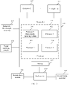
- FIG. 4 is a schematic diagram of a hardware structure principle according to an embodiment of the present invention.
- a first crystal oscillator is a temperature compensated crystal oscillator
- a first clock module is an RTC clock chip (that is, a real-time clock chip)
- a satellite signal receiving module may be a GNSS module
- an end point EP is a sensor.
- a hardware structure of the master SoC includes the processor 301, the processor 302, the processor 303, the processor 304, the memory 112, a bus bridge 401, a system bus 402, an I/O interface 403, a network interface 404, and the like.
- the master SoC is further connected to the GNSS module 308 through I (a dedicated CAN bus) shown in the figure to receive a GNSS signal, connected to an RTC clock chip 306 through II (such as an SPI or IIC bus) shown in the figure to obtain real real time, connected to a sensor 406 through the I/O interface 403, to provide a time reference for the end point 307, for example, a sensor, and connected to the temperature compensated crystal oscillator 305 on a circuit board, to obtain an oscillation frequency of the temperature compensated crystal oscillator, so as to maintain operating of system time.
- the master SoC may be further connected to a network through the network interface, to obtain required information or real-time data.
- FIG. 5 is a schematic diagram of a principle of providing a time source for autonomous driving according to an embodiment of the present invention.
- the processor 301, the processor 302 (running an AO OS), the processor 303, the processor 304, the GNSS module (namely, a signal receiving module) 308, the temperature compensated crystal oscillator 305, and the board RTC (namely, a board real-time clock chip) 306 in the master SoC 110 are used as examples for description.
- Two sets of clocks are deployed in the processor 301 of the master SoC, which are a first time source OS-CLK and a second time source GNSS-CLK.
- the OS-CLK operates relying on the board temperature compensated crystal oscillator 305 regardless of whether a vehicle can receive a GNSS signal.
- the GNSS-CLK traces GNSS time provided by a satellite based on the GNSS signal.
- the GNSS-CLK switches, based on a message feedback (the GNSS module is connected to a C interface (namely, a CAN interface, where the CAN interface is represented by the C interface in the following, and this is not be described later)) from the GNSS module, to maintaining normal operating of time in the system by using the temperature compensated crystal oscillator.
- the board RTC provides bootup time for the master SoC and the backup SoC. The bootup time is used for setting of OS-CLKs and GNSS-CLKs in the two SoCs. As shown in FIG.
- the processor 301 sends a time synchronization message (Anounce/Sync packet) to a local area network switch (LAN Switch) through a network interface M (for example, the network interface M is a ten-gigabit Ethernet interface (Ten-GigabitEthernet, XGE). Then, the local area network switch is used as a boundary clock to send the time synchronization message to a plurality of end points, so as to ensure time synchronization of each time point.
- the processor 301 may further provide a time synchronization message of the OS-CLK for the processor 303, and provide a time synchronization message of the GNSS-CLK for the processor 304. It may be understood that, a time stabilization principle and a structure of the backup SoC are basically the same as those of the master SoC. Details are not described herein again.
- the OS-CLK of the backup OS in the backup SoC is further used to trace the OS-CLK of a master OS in the master SoC.
- FIG. 6A and FIG. 6B are a schematic diagram of another principle of providing a time source for autonomous driving according to an embodiment of the present invention. As shown in FIG. 6A and FIG. 6B , both the processor 302 and the processor 302' run a same AO OS. An operating principle of the GNSS-CLK of the backup SoC is the same as that of the GNSS-CLK of the master SoC, and the master SoC and the backup SoC are connected to a same signal receiving module (that is, the GNSS module 308).
- the master SoC and the backup SoC are connected to different temperature compensated crystal oscillators.
- the OS-CLK of the backup SoC is based on time of the OS-CLK of the master SoC (namely, a master chip). Therefore, when the master SoC operates normally, the backup SoC (namely, a backup chip) can be used as a secondary master clock of the OS-CLK of the master SoC to provide a time reference for another end point. That is, a network interface or port of the OS-CLK of the master SoC for connecting to a point is expanded.
- a LAN switch 1 (LSW 1) shown in FIG. 6A and FIG. 6B receives both a time synchronization message from the master SoC and a time synchronization message from the backup SoC.
- the LSW 1 can select the time synchronization message sent by the master SoC.
- Each LSW is connected to corresponding network interfaces of the master SoC and the backup SoC. As shown in FIG. 6A and FIG.
- a LAN switch 0/LAN switch 1 functions as an internal switching node, runs a gPTP protocol stack inside, functions as an 802.1AS boundary clock, receives and processes a gPTP packet sent by a master port on a master plane through one of ports, calculates an offset (a time offset and a frequency offset) between a local clock and a master clock and a path delay based on a protocol algorithm, adjusts the local clock and the master clock to implement synchronization of 10 us-level precision (this step is optional, and is similar to forwarding, by a transparent clock of 1588, a gPTP event message after only residence time of the gPTP event message is corrected), and becomes a secondary master clock in a current synchronization network.
- time synchronization messages such as Anounce and Sync packets may be continuously sent, through the master clock port of the device, to an end point (End Point) whose time needs to be synchronized, for example, a sensor point, for example, a vehicle-mounted radar or a millimeter-wave radar.
- End Point a sensor point
- a sensor used as an end point runs gPTP protocol stack software to receive and process Anounce and Sync packets, calculates and adjusts an offset between the local clock and a GMC clock and a path transmission delay based on timestamp information carried in the packets, adjusts time of the local clock to maintain synchronization with GMC time.
- time offsets between all destination end points and the GMC time are controlled within a set range, for example, within 10 us.
- FIG. 6A and FIG. 6B is an extension of the content shown in FIG. 5 , and corresponding content such as the processor 303, the processor 304, and the processor 302 that are not involved in FIG. 6A and FIG. 6B is not described herein.
- FIG. 7 is a schematic flowchart of the method for providing a time source for autonomous driving according to an embodiment of the present invention. As shown in FIG. 7 , the method is performed by the processor 301 (namely, a first processor), and may include step S701 and step S702.
- Step S701 Provide a first time source for a first subsystem of an autonomous driving system by using a first crystal oscillator, and provide a second time source for a second subsystem of the autonomous driving system based on a received satellite time signal.
- FIG. 8 is a schematic diagram of generating a time source according to an embodiment of the present invention.
- a GNSS module can receive a GNSS signal (that is, a satellite time signal), to ensure security of autonomous driving
- the first time source that is, an OS-CLK
- the first time source operates completely relying on a board temperature compensated crystal oscillator (for example, precision of the board temperature compensated crystal oscillator is 10 ppm).
- a hardware clock in an M network interface is adjusted to same time as that of the OS-CLK.
- a master port (namely, the M network interface) sends Anounce and Sync packets (namely, time synchronization messages) at a frequency required by a gPTP protocol, so that the OS-CLK becomes a master clock of an entire network.
- a reference frequency is provided for the second time source (that is, a GNSS-CLK) based on the GNSS signal, and the GNSS-CLK is adjusted to ensure synchronization with a GNSS time source (that is, GNSS time of a satellite).
- a difference between the GNSS-CLK and the GNSS time source is within 10 us.
- the OS-CLK is dedicated to a computing service (that is, a service of the first subsystem) for autonomous driving, operates only relying on a board crystal oscillator after bootup, and serves as a root clock (or referred to as a master clock) in a time synchronization network in the system to provide a global time source for another node on an autonomous driving plane.
- the GNSS-CLK is used for a vehicle management-related service (that is, a service of the second subsystem).
- service planes in the vehicle include a driving plane and a management plane.
- the driving plane is used for processing data related to vehicle driving calculation
- the management plane is used for processing data related to audit, log recording, and travel data management. Both the driving plane and the management plane may be considered to include or correspond to one or more subsystems, such as a travel system, a sensor system, and a control system.
- the GNSS signal (including a time position) is directly accessed to the system through a CAN bus and a PPS clock signal cable.
- both a master SoC and a backup SoC can receive the GNSS signal. Receiving the GNSS signal in this manner ensures that a GNSS-CLK of the master SoC and a GNSS-CLK of the backup SoC can effectively receive the GNSS signal, ensures consistency of signal transmission, and further ensures stability of a subsequent time source.
- providing the second time source for the second subsystem of the autonomous driving system based on the received satellite time signal includes: generating the second time source by using the satellite time signal as a reference frequency of the second time source, where the satellite time signal is received by using a signal receiving module; and providing the second time source for the second subsystem.
- Step S702 When the satellite time signal is not received, provide the second time source for the second subsystem by using the first crystal oscillator.
- FIG. 9 is another schematic diagram of generating a time source according to an embodiment of the present invention.
- a GNSS module when a GNSS module cannot trace a satellite (that is, cannot receive a GNSS signal), the GNSS module also outputs time, but the time may drift slowly.
- a GNSS-CLK After receiving a feedback from the GNSS module, a GNSS-CLK generally does not continue to trace the time output by the GNSS module, but maintains a normal timing service of system time relying on the first crystal oscillator.
- An OS-CLK that is, the first time source
- a UTC time service is provided.
- the OS-CLK clock traces GNSS time and provides UCT time for services on a management plane.
- the GNSS-CLK may be a hardware clock of a network interface that does not need to participate in time synchronization or may be implemented through software.
- the GNSS-CLK is implemented after the vehicle is cold started or woken up from a sleep state and after initial bootup time is provided by the AO OS.
- a GNSS time source is traced.
- the GNSS-CLK is time-synchronized by using a crystal oscillator of the GNSS-CLK, to meet a UTC time requirement of a management plane service.
- time jumping may occur when the GNSS time is traced, but does not affect security of autonomous driving, and an impact on time accuracy of management plane data is insignificant.
- the GNSS-CLK clock needs to in some embodimentss encapsulate a user-mode API and a kernel-mode API for a module that requires accurate UTC time.
- the user-mode API is provided for a user and is used to perform operation and adjustment on time information in a management subsystem in a normal case.
- the kernel-mode API is provided for the user and is used to perform manual operation and adjustment on the system time when necessary. The operation and adjustment have great impact on the system.
- the user needs to obtain permission to perform operation on the system time through the kernel-mode API. It may be understood that, operations such as time synchronization are operations performed at a kernel level.
- the user When the user wants to obtain time (for example, a date of maintenance and test logs) in the management subsystem, the user can obtain only processed time information through only the user-mode interface, and cannot obtain underlying time of the system through only the user-mode interface. The user obtains the underlying time of the system through the kernel-mode interface.
- time for example, a date of maintenance and test logs
- bootup time is obtained from a first clock module, where the bootup time is bootup time of the first time source and the second time source.
- FIG. 10 is a schematic diagram of setting bootup time according to an embodiment of the present invention.
- an AO OS that is, an operating system run by the processor 302 obtains the bootup time or a bootup time point (for example, 13:40) from the board real-time clock chip (that is, the board RTC, board RTC) 306.
- the bootup time is set as bootup time of the master OS (that is, the processor 301).
- the bootup time is set as bootup time of an OS-CLK and a GNSS-CLK.
- the AO OS obtains the bootup time from a real-time clock of the board RTC to set bootup time of an OS-CLK and a GNSS-CLK on a master plane.
- FIG. 11 is a schematic diagram of a master/backup SoC connection according to an embodiment of the present invention. As shown in 2 in FIG. 11 , the master SoC is connected to the temperature compensated crystal oscillator 305, and the temperature compensated crystal oscillator 305 provides a reference oscillation frequency for an OS-CLK.
- the OS-CLK is used as a master clock in a corresponding clock system, and provides time references for the processor 303 (configured to process an autonomous driving-related service), a plurality of M network interfaces (used to send a time synchronization message to an end point), and the backup SoC 110'.
- the master SoC and the backup SoC are connected to different temperature compensated crystal oscillators.
- an error can be corrected through connection between the M network port and the S network port.
- the backup SoC relies on different temperature compensated crystal oscillators, when the master SoC operates normally, the OS-CLK of the master SoC is still traced to be used as the time reference.
- a master port clock is a clock role specified in the gPTP protocol.
- a slave port clock is a clock role specified in the gPTP protocol.
- the slave port clock cannot send a time synchronization message externally, only receives and processes a synchronization message sent by an upper-level master clock, and needs to be adjusted to synchronize with the master clock.
- the master SoC and the backup SoC constitute a pair of master and slave port clocks. It may be understood that the master SoC and another boundary clock or a lower-level point also constitute a pair of master and slave port clocks.
- the method further includes: synchronizing a third time source based on the second time source and a preset adjustment periodicity, where the third time source is a time source provided by a first clock module.
- FIG. 12 is a schematic flowchart of adjusting a time source according to an embodiment of the present invention. As shown in 1 to 4 in FIG. 12 , first, in an adjustment periodicity, current GNSS time fed back by the GNSS module is received through a GNSS interface. The GNSS-CLK traces a GNSS signal. RTC time is synchronized with the GNSS time of the GNSS-CLK through the AO OS.
- initial bootup time of a clock OS-CLK related to autonomous driving calculation is provided by the AO OS after the vehicle is cold started or woken from a sleep state. Then, the OS clock operates completely relying on a crystal oscillator of the OS clock, and no longer traces the GNSS time source. Another point on the board traces, based on the gPTP protocol, the OS-CLK to implement network-wide clock synchronization. In this case, due to drift of the crystal oscillator of the OS clock, the OS-CLK gradually offsets, and a clock of another node also offsets. Therefore, during autonomous driving, the GNSS-CLK is used to periodically adjust an RTC clock to keep the RTC clock synchronized with the GNSS clock. In this way, a difference between time of the autonomous driving system and UTC time is not large, and this effectively prevents infinite drift of time of the OS-CLK.
- the OS-CLK of an autonomous driving plane mainly operates relying on self-oscillation of a board temperature compensated crystal oscillator.
- health monitoring needs to be performed on an operating status of the temperature compensated crystal oscillator.
- a timing (for example, 50 ms) monitoring program is designed to prevent time jumping of a root clock due to the abnormality of the crystal oscillator from affecting security of autonomous driving. Therefore, the OS-CLK is monitored and adjusted based on a monitoring algorithm provided in this embodiment of the present invention.
- OS_CLK Frequency is a clock frequency of the first time source
- GNSS_CLK Frequency is a clock frequency of the second time source
- RTC_CLK Frequency is a clock frequency of the third time source.
- a frequency of each physical clock actually jitters. Therefore, a frequency ratio of the two clocks also jitters.
- timestamp sequences of two clocks can be measured periodically and continuously. A size of the timestamp sequence is fixed. For example, 7 to 10 timestamps are stored in the timestamp sequence of each clock.
- the timestamp sequence may be implemented through a queue. After the queue is full, each time a new timestamp enters the queue, an oldest timestamp at the tail of the queue is eliminated. Then, a ratio of differences obtained by subtracting first and last timestamps of the timestamp sequences of the two clocks is: CLK 1 TN ⁇ CLK 1 T 0 CLK 0 TN ⁇ CLK 0 T 0 .
- TN may be a seventh timestamp
- TO may be the first timestamp.
- the difference is a time period between the first timestamp and the seventh timestamp.
- FR CLK 0 FrequeNcy CLK 1 FrequeNcy .
- abs ( FR 1 - FR 1 AVG ) is an absolute value of a difference between the first frequency ratio and the historical first frequency ratio
- abs ( FR 2 - FR 2 AVG ) is an absolute value of a difference between the second frequency ratio and the historical second frequency ratio
- abs ( FR 3 - FR 3 AVG ) is an absolute value of a difference between the third frequency ratio and the historical third frequency ratio.
- a currently and recently measured frequency ratio of the two CLKs may be marked as FR _ Curr (that is, FR1 in the foregoing formula), and ⁇ FR is defined as a difference between the current frequency ratio and a historical average frequency ratio.
- ⁇ FR changes within a proper value range that can be expected, and a probability that frequencies of the three groups of clocks hop or fail at the same time can be infinitely low. Therefore, it can be inferred that if an ⁇ FR suddenly becomes larger than a preset threshold, one of the two clocks may be faulty.
- the specific one can be found through three comparisons, for example, comparing any two of the frequency ratio change ⁇ FR1 between the OS-CLK and the GNSS-CLK, the frequency ratio change ⁇ FR2 between the OS-CLK and the RTC-CLK, and the frequency ratio change ⁇ FR 3 between the GNSS-CLK and the RTC-CLK.
- a clock whose crystal oscillator is abnormal is determined based on a voting principle. If ⁇ FR 1 and ⁇ FR 2 suddenly becomes larger than the threshold, but ⁇ FR 3 is within the normal range, it is determined that a frequency of the crystal oscillator of the OS-CLK clock is abnormal.
- a clock exception alarm needs to be reported to an upper-layer management plane.
- the following provides a method for calculating the historical frequency average value, and the method further includes:
- fr 1 1 , fr 1 2 , fr 1 3 , ..., and fr1 N are respectively a 1 st first frequency ratio, a 2 nd first frequency ratio, a 3 rd first frequency ratio, ..., and an N th first frequency ratio
- fr 2 1 , fr 2 2 , fr 2 3 , ..., and fr 2 N are respectively a 1 st second frequency ratio, a 2 nd second frequency ratio, a 3 rd second frequency ratio, ..., and an N th second frequency ratio
- fr 3 1 , fr 3 2 , fr 3 3 , ..., and fr 3 N are respectively a 1 st third frequency ratio, a 2 nd third frequency ratio, a 3 rd third frequency ratio, ..., and an N th third frequency ratio.
- N may represent the latest sample quantity of frequency ratios, and may have a value between 7 and 10.
- the foregoing crystal oscillator failure detection method is implemented by software, and the software needs to collect, process, and calculate a large amount of data, and also relies on a scheduling policy of the OS. Consequently, a detection result may not be timely.
- the method may be implemented by a dedicated hardware logic circuit.
- hardware detection logic is written into a board CPLD component to implement quicker and more accurate crystal oscillator failure detection.
- FIG. 13 is a schematic diagram of a structure of an apparatus for providing a time source for autonomous driving according to an embodiment of the present invention.
- the apparatus 131 for providing a time source for autonomous driving includes a first time source unit 131, a second time source unit 132, an adjustment unit 133, a calculation unit 134, a comparison unit 135, a determining unit 136, a measurement unit 137, and a historical frequency ratio unit 138.
- the first time source unit 131 is configured to provide a first time source for a first subsystem of an autonomous driving system by using a first crystal oscillator, and provide a second time source for a second subsystem of the autonomous driving system based on a received satellite time signal.
- the apparatus further includes the second time source unit 132, configured to: when the satellite time signal is not received, provide the second time source for the second subsystem by using the first crystal oscillator.
- the first time source unit 131 is In some embodiments configured to:
- the apparatus further includes the adjustment unit 133, configured to: synchronize a third time source based on the second time source and a preset adjustment periodicity, where the third time source is a time source provided by a first clock module.
- the apparatus further includes:
- OS_CLK Frequency is a clock frequency of the first time source
- GNSS_CLK Frequency is a clock frequency of the second time source
- RTC_CLK Frequency is a clock frequency of the third time source.
- abs ( FR 1 - FR 1 AVG ) is an absolute value of a difference between the first frequency ratio and the historical first frequency ratio
- abs ( FR 2 - FR 2 AVG ) is an absolute value of a difference between the second frequency ratio and the historical second frequency ratio
- abs ( FR 3 - FR 3 AVG ) is an absolute value of a difference between the third frequency ratio and the historical third frequency ratio.
- the apparatus further includes:
- fr 1 1 , fr 1 2 , fr 1 3 , ..., and fr 1 N are respectively a 1 st first frequency ratio, a 2 nd first frequency ratio, a 3 rd first frequency ratio, ..., and an N th first frequency ratio
- fr 2 1 , fr 2 2 , fr 2 3 , ..., and fr 2 N are respectively a 1 st second frequency ratio, a 2 nd second frequency ratio, a 3 rd second frequency ratio, ..., and an N th second frequency ratio
- fr 3 1 , fr 3 2 , fr 3 3 , ..., and fr 3 N are respectively a 1 st third frequency ratio, a 2 nd third frequency ratio, a 3 rd third frequency ratio, ..., and an N th third frequency ratio.
- the first crystal oscillator is a temperature compensated crystal oscillator.
- FIG. 14 is a schematic diagram of a structure of a chip according to an embodiment of the present invention.
- An apparatus 13 for providing a time source for autonomous driving may be implemented by using the structure in FIG. 14 .
- a device 14 includes at least one processor 141 and at least one memory 142.
- the device may further include general components such as an antenna, and details are not described herein.
- the processor 141 may be a general-purpose central processing unit (CPU), a microprocessor, an application-specific integrated circuit (application-specific integrated circuit, ASIC), or one or more integrated circuits for controlling program execution of the foregoing solution.
- CPU central processing unit
- ASIC application-specific integrated circuit
- the memory 142 may be a read-only memory (read-only memory, ROM) or another type of static storage device that can store static information and instructions, a random access memory (random access memory, RAM) or another type of dynamic storage device that can store information and instructions, an electrically erasable programmable read-only memory (Electrically Erasable Programmable Read-Only Memory, EEPROM), a compact disc read-only memory (Compact Disc Read-Only Memory, CD-ROM) or another compact disc storage, optical disc storage (including a compressed optical disc, a laser disc, an optical disc, a digital versatile disc, a blue-ray optical disc, and the like), a magnetic disk storage medium or another magnetic storage communications device, or any other medium that can be configured to carry or store expected program code in a form of instructions or a data structure and that can be accessed by a computer.
- the memory 142 is not limited thereto.
- the memory may exist independently, and is connected to the processor by using the bus. Alternatively, the memory may be integrated
- the memory 142 is configured to store application code for executing the foregoing solutions, and the processor 141 controls the execution.
- the processor 141 is configured to execute the application code stored in the memory 142.
- the code stored in the memory 142 may be used to execute the method for providing a time source for autonomous driving that is provided in FIG. 7 .
- a first time source is provided for a first subsystem of an autonomous driving system by using a first crystal oscillator
- a second time source is provided for a second subsystem of the autonomous driving system based on the received satellite time signal.
- FIG. 15 is a schematic diagram of a vehicle according to an embodiment of the present invention.
- the vehicle 15 includes a vehicle-mounted computer 151, and may receive a satellite time signal sent by a satellite 16.
- the vehicle-mounted computer may perform some or all of the steps recorded in any one of the method embodiments corresponding to FIG. 7 to FIG. 12 . For example, when a satellite time signal is received, a first time source operating relying on a first crystal oscillator and a second time source operating relying on the satellite signal are provided.
- the vehicle may further include a backup vehicle-mounted computer, to avoid a single point failure in the autonomous driving system, and improve overall system reliability.
- the disclosed apparatuses may be implemented in other manners.
- the described apparatus embodiment is merely an example.
- division into the units is merely logical function division and may be other division in an actual implementation.
- a plurality of units or components may be combined or integrated into another system, or some features may be ignored or not performed.
- the displayed or discussed mutual couplings or direct couplings or communication connections may be implemented by using some interfaces.
- the indirect couplings or communication connections between the apparatuses or units may be implemented in electronic, mechanical, or other forms.
- the foregoing units described as separate parts may or may not be physically separate, and parts displayed as units may or may not be physical units, may be located in one position, or may be distributed on a plurality of network units. Some or all of the units may be selected based on actual needs to achieve the objectives of the solutions of embodiments.
- function units in embodiments of this application may be integrated into one processing unit, or each of the units may exist alone physically, or two or more units are integrated into one unit.
- the integrated unit may be implemented in a form of hardware, or may be implemented in a form of a software function unit.
- the technical solutions in this application essentially, or the part contributing to the prior art, or all or some of the technical solutions may be implemented in the form of a software product.
- the computer software product is stored in a storage medium and includes several instructions for instructing a computer device (which may be a personal computer, a server, or a network device, and may be in some embodiments a processor in a computer device) to perform all or some steps of the foregoing methods described in embodiments of this application.
- the foregoing storage medium may include any medium that can store program code, such as a USB flash drive, a removable hard disk, a magnetic disk, an optical disc, a read-only memory (Read-Only Memory, ROM for short), or a random access memory (Random Access Memory, RAM for short).
- program code such as a USB flash drive, a removable hard disk, a magnetic disk, an optical disc, a read-only memory (Read-Only Memory, ROM for short), or a random access memory (Random Access Memory, RAM for short).
Landscapes
- Engineering & Computer Science (AREA)
- Theoretical Computer Science (AREA)
- General Physics & Mathematics (AREA)
- Physics & Mathematics (AREA)
- Computer Networks & Wireless Communication (AREA)
- Signal Processing (AREA)
- General Engineering & Computer Science (AREA)
- Transportation (AREA)
- Human Computer Interaction (AREA)
- Aviation & Aerospace Engineering (AREA)
- Mechanical Engineering (AREA)
- Automation & Control Theory (AREA)
- Astronomy & Astrophysics (AREA)
- Electric Clocks (AREA)
- Oscillators With Electromechanical Resonators (AREA)
- Traffic Control Systems (AREA)
- Synchronisation In Digital Transmission Systems (AREA)
Applications Claiming Priority (1)
| Application Number | Priority Date | Filing Date | Title |
|---|---|---|---|
| PCT/CN2019/119754 WO2021097718A1 (zh) | 2019-11-20 | 2019-11-20 | 一种为自动驾驶提供时间源的方法及装置 |
Publications (2)
| Publication Number | Publication Date |
|---|---|
| EP4044467A1 true EP4044467A1 (de) | 2022-08-17 |
| EP4044467A4 EP4044467A4 (de) | 2022-11-30 |
Family
ID=75980342
Family Applications (1)
| Application Number | Title | Priority Date | Filing Date |
|---|---|---|---|
| EP19953177.3A Pending EP4044467A4 (de) | 2019-11-20 | 2019-11-20 | Verfahren und vorrichtung zum bereitstellen einer zeitquelle für einen automatischen antrieb |
Country Status (5)
| Country | Link |
|---|---|
| US (1) | US20220278745A1 (de) |
| EP (1) | EP4044467A4 (de) |
| JP (1) | JP7385033B2 (de) |
| CN (1) | CN114641951A (de) |
| WO (1) | WO2021097718A1 (de) |
Cited By (1)
| Publication number | Priority date | Publication date | Assignee | Title |
|---|---|---|---|---|
| EP4328675A1 (de) * | 2022-08-23 | 2024-02-28 | Xiaomi EV Technology Co., Ltd. | Fahrzeugmontierte steuerung und verfahren zur ausgabe der absoluten zeit eines fahrzeugs und fahrzeug |
Families Citing this family (8)
| Publication number | Priority date | Publication date | Assignee | Title |
|---|---|---|---|---|
| CN114647179A (zh) * | 2020-12-18 | 2022-06-21 | 华为技术有限公司 | 主时钟装置、从时钟装置和时间同步方法 |
| CN115913430A (zh) * | 2021-08-16 | 2023-04-04 | 华为技术有限公司 | 控制系统的时钟同步方法以及控制系统 |
| CN115882989A (zh) * | 2021-09-27 | 2023-03-31 | 华为技术有限公司 | 一种时钟同步的方法、装置和车辆 |
| WO2023141817A1 (zh) * | 2022-01-26 | 2023-08-03 | 华为技术有限公司 | 一种时间同步方法、装置及存储介质 |
| US20230319742A1 (en) * | 2022-04-05 | 2023-10-05 | Meta Platforms, Inc. | Peripheral time server device |
| CN115348657B (zh) * | 2022-08-15 | 2024-02-13 | 小米汽车科技有限公司 | 用于车辆时间同步的系统、方法及车辆 |
| CN115694704A (zh) * | 2022-10-28 | 2023-02-03 | 重庆长安汽车股份有限公司 | 一种时间同步方法、装置、设备及存储介质 |
| CN115842599A (zh) * | 2022-11-30 | 2023-03-24 | 重庆长安汽车股份有限公司 | 自动驾驶的冗余时间同步方法、装置、系统车辆及介质 |
Family Cites Families (14)
| Publication number | Priority date | Publication date | Assignee | Title |
|---|---|---|---|---|
| JP2001221874A (ja) * | 2000-02-14 | 2001-08-17 | Toshiba Corp | 時刻同期方式 |
| CN101068133B (zh) * | 2007-06-12 | 2011-05-04 | 华为技术有限公司 | 时间同步方法、网络通信系统及其设备 |
| US9369225B2 (en) * | 2012-10-01 | 2016-06-14 | Intel Deutschland Gmbh | Distribution of an electronic reference clock signal that includes delay and validity information |
| CN103913987B (zh) * | 2014-04-26 | 2017-04-05 | 广西电网公司电力科学研究院 | Gps授时系统及其获得精确时间基准的方法 |
| US10021661B2 (en) * | 2015-11-24 | 2018-07-10 | At&T Mobility Ii Llc | Meshed GPS time synchronized network |
| US10101747B2 (en) * | 2015-12-11 | 2018-10-16 | Uber Technologies, Inc. | Formatting sensor data for use in autonomous vehicle communications platform |
| US10539929B2 (en) * | 2016-10-11 | 2020-01-21 | Northrop Grumman Systems Corporation | Atomic clock system |
| JP2019008709A (ja) | 2017-06-28 | 2019-01-17 | 京セラ株式会社 | 車両、情報処理システム、情報処理装置、およびデータ構造 |
| US11349589B2 (en) | 2017-08-04 | 2022-05-31 | Metrom Rail, Llc | Methods and systems for decentralized rail signaling and positive train control |
| US10566084B2 (en) | 2017-08-23 | 2020-02-18 | Ntt Innovation Institute, Inc. | System and method for racing data analysis using telemetry data and wearable sensor data |
| US20190286151A1 (en) | 2018-03-14 | 2019-09-19 | GM Global Technology Operations LLC | Automated driving systems and control logic for cloud-based scenario planning of autonomous vehicles |
| US20190313224A1 (en) | 2018-04-10 | 2019-10-10 | GM Global Technology Operations LLC | Automated vehicle systems and control logic for smart data exchanges using enhanced bloom filters |
| US10365364B1 (en) | 2018-05-18 | 2019-07-30 | Zendar Inc. | Systems and methods for detecting objects |
| EP3963363A4 (de) * | 2019-04-30 | 2023-08-02 | Zendar Inc. | Systeme und verfahren zur kombination von radardaten |
-
2019
- 2019-11-20 JP JP2022529367A patent/JP7385033B2/ja active Active
- 2019-11-20 EP EP19953177.3A patent/EP4044467A4/de active Pending
- 2019-11-20 WO PCT/CN2019/119754 patent/WO2021097718A1/zh unknown
- 2019-11-20 CN CN201980102106.3A patent/CN114641951A/zh active Pending
-
2022
- 2022-05-19 US US17/748,849 patent/US20220278745A1/en active Pending
Cited By (1)
| Publication number | Priority date | Publication date | Assignee | Title |
|---|---|---|---|---|
| EP4328675A1 (de) * | 2022-08-23 | 2024-02-28 | Xiaomi EV Technology Co., Ltd. | Fahrzeugmontierte steuerung und verfahren zur ausgabe der absoluten zeit eines fahrzeugs und fahrzeug |
Also Published As
| Publication number | Publication date |
|---|---|
| JP7385033B2 (ja) | 2023-11-21 |
| US20220278745A1 (en) | 2022-09-01 |
| EP4044467A4 (de) | 2022-11-30 |
| JP2023502671A (ja) | 2023-01-25 |
| CN114641951A (zh) | 2022-06-17 |
| WO2021097718A1 (zh) | 2021-05-27 |
Similar Documents
| Publication | Publication Date | Title |
|---|---|---|
| US20220278745A1 (en) | Method and apparatus for providing time source for autonomous driving | |
| US10788841B2 (en) | Hardware centralized time synchronization hub for an autonomous driving vehicle | |
| CN110857993B (zh) | 用于自动驾驶车辆基于gps的高精度时间戳生成电路 | |
| EP3613648B1 (de) | Zeitquellenrückgewinnungssystem für ein autonom fahrendes fahrzeug | |
| US20200116502A1 (en) | Sensor integration and synchronization unit for an autonomous driving vehicle | |
| WO2021047271A1 (zh) | 一种时间同步方法及装置 | |
| CN110858786B (zh) | 用于自动驾驶车辆的时间源排序系统 | |
| US11269077B2 (en) | Flexible test board to improve sensor i/o coverage for autonomous driving platform | |
| CN113110160B (zh) | 域控制器的时间同步方法、装置、域控制器和存储介质 | |
| CN112752954A (zh) | 自动驾驶车辆的同步传感器 | |
| CN111077841A (zh) | 一种基于双can总线的无人机飞行控制系统 | |
| WO2022116000A1 (zh) | 一种通信方法及装置 | |
| CN111600670A (zh) | 感应数据计算控制方法以及授时装置 | |
| CN209928279U (zh) | 智能驾驶系统及智能车辆 | |
| CN115348657B (zh) | 用于车辆时间同步的系统、方法及车辆 | |
| EP4209901A1 (de) | Multitask-einsatzverfahren und -vorrichtung | |
| WO2022127337A1 (zh) | 主时钟装置、从时钟装置和时间同步方法 | |
| CN114189306B (zh) | 数据同步系统、方法和装置 | |
| US20240069217A1 (en) | Vehicle-mounted controller and method for issuing absolute time of vehicle and vehicle | |
| WO2023044802A1 (zh) | 时间同步方法及相关装置 | |
| WO2023184124A1 (zh) | 控制系统、确定接管控制器的方法及装置 | |
| US20240159561A1 (en) | Method for supplying an electronic horizon for an autonomous motor vehicle | |
| CN116455498A (zh) | 一种授时方法、系统和智能驾驶设备 | |
| CN115882989A (zh) | 一种时钟同步的方法、装置和车辆 | |
| CN114978397A (zh) | 自动驾驶整车的时钟和频率的同步方法、装置和电子设备 |
Legal Events
| Date | Code | Title | Description |
|---|---|---|---|
| STAA | Information on the status of an ep patent application or granted ep patent |
Free format text: STATUS: THE INTERNATIONAL PUBLICATION HAS BEEN MADE |
|
| PUAI | Public reference made under article 153(3) epc to a published international application that has entered the european phase |
Free format text: ORIGINAL CODE: 0009012 |
|
| STAA | Information on the status of an ep patent application or granted ep patent |
Free format text: STATUS: REQUEST FOR EXAMINATION WAS MADE |
|
| 17P | Request for examination filed |
Effective date: 20220513 |
|
| AK | Designated contracting states |
Kind code of ref document: A1 Designated state(s): AL AT BE BG CH CY CZ DE DK EE ES FI FR GB GR HR HU IE IS IT LI LT LU LV MC MK MT NL NO PL PT RO RS SE SI SK SM TR |
|
| A4 | Supplementary search report drawn up and despatched |
Effective date: 20221102 |
|
| RIC1 | Information provided on ipc code assigned before grant |
Ipc: H04W 56/00 20090101ALI20221026BHEP Ipc: H04B 7/185 20060101ALI20221026BHEP Ipc: G05D 1/02 20200101ALI20221026BHEP Ipc: B60W 60/00 20200101ALI20221026BHEP Ipc: H04J 3/06 20060101AFI20221026BHEP |
|
| DAV | Request for validation of the european patent (deleted) | ||
| DAX | Request for extension of the european patent (deleted) |