EP4044442B1 - Uplink-übertragungsverfahren und kommunikationsvorrichtung - Google Patents
Uplink-übertragungsverfahren und kommunikationsvorrichtung Download PDFInfo
- Publication number
- EP4044442B1 EP4044442B1 EP19950579.3A EP19950579A EP4044442B1 EP 4044442 B1 EP4044442 B1 EP 4044442B1 EP 19950579 A EP19950579 A EP 19950579A EP 4044442 B1 EP4044442 B1 EP 4044442B1
- Authority
- EP
- European Patent Office
- Prior art keywords
- time domain
- uplink
- resource
- terminal
- sidelink
- Prior art date
- Legal status (The legal status is an assumption and is not a legal conclusion. Google has not performed a legal analysis and makes no representation as to the accuracy of the status listed.)
- Active
Links
Images


Classifications
-
- H—ELECTRICITY
- H04—ELECTRIC COMMUNICATION TECHNIQUE
- H04W—WIRELESS COMMUNICATION NETWORKS
- H04W72/00—Local resource management
- H04W72/12—Wireless traffic scheduling
-
- H—ELECTRICITY
- H04—ELECTRIC COMMUNICATION TECHNIQUE
- H04W—WIRELESS COMMUNICATION NETWORKS
- H04W72/00—Local resource management
- H04W72/20—Control channels or signalling for resource management
- H04W72/23—Control channels or signalling for resource management in the downlink direction of a wireless link, i.e. towards a terminal
-
- H—ELECTRICITY
- H04—ELECTRIC COMMUNICATION TECHNIQUE
- H04B—TRANSMISSION
- H04B7/00—Radio transmission systems, i.e. using radiation field
- H04B7/02—Diversity systems; Multi-antenna system, i.e. transmission or reception using multiple antennas
- H04B7/022—Site diversity; Macro-diversity
- H04B7/026—Co-operative diversity, e.g. using fixed or mobile stations as relays
-
- H—ELECTRICITY
- H04—ELECTRIC COMMUNICATION TECHNIQUE
- H04W—WIRELESS COMMUNICATION NETWORKS
- H04W88/00—Devices specially adapted for wireless communication networks, e.g. terminals, base stations or access point devices
- H04W88/02—Terminal devices
- H04W88/04—Terminal devices adapted for relaying to or from another terminal or user
Definitions
- This application relates to the communication field, and in particular, to uplink transmission methods and a communication apparatus.
- a first generation wireless communication system based on an analog communication system a 2G wireless communication system represented by a global system for mobile communications (global system for mobile communications, GSM), a 3G wireless communication system represented by wideband code division multiple access (wideband code division multiple access, WCDMA), and a 4G wireless communication system, such as long term evolution (long term evolution, LTE), that now has been widely put into commercial use in the world and has achieved great success successively appear.
- Services supported by the wireless communication system are also developed from initial voice and SMS message services to currently supported wireless high-speed data communication.
- sidelink transmission may be completed between terminal devices on a sidelink resource
- uplink transmission may be completed between a terminal device and a network device on an uplink resource
- downlink transmission may be completed between the terminal device and the network device on a downlink resource.
- user cooperative transmission is further supported.
- User cooperation means that a terminal device may complete user cooperative transmission, for example, uplink cooperative transmission and/or downlink cooperative transmission, with a network device with the assistance of another terminal device.
- Uplink cooperative transmission means that a second terminal receives data from a first terminal on a first sidelink resource, and forwards the data to a network device on an uplink resource.
- Downlink cooperative transmission means that the second terminal receives data from the network device on an uplink resource, and forwards the data to the first terminal on a second sidelink resource.
- the uplink resource is located after the first sidelink resource in time domain, and the second sidelink resource is located after the downlink resource in time domain, so that CUE has sufficient time to complete a data forwarding operation.
- 3GPP DRAFT R1-1704308 discloses that when both relay UE and remote UE are in coverage, the resources for communication between relay UE and remote UE are configured and allocated by eNB, and when remote UE is out of coverage, relay UE assisted resource allocation can be considered.
- 3GPP DRAFT R1-154548 discloses that eNodeB needs to know resource allocation used for Remote UE SL Tx to coordinate resource allocation between two links for Realy UE UL Tx and Relay UE SL Rx and between two links for Realy UE SL Tx and Relay UE SL Rx.
- WO 2018/157673 A1 discloses a method for implementing user equipment cooperation.
- the method includes: generating, by an access network device, cooperative control information, where the cooperative control information is used to instruct first user equipment to perform sidelink transmission in a first transmission unit of a first subframe and perform uplink transmission in a second transmission unit of the first subframe, the first transmission unit is adjacent to the second transmission unit, and the sidelink transmission includes that the first user equipment sends feedback information to second user equipment and that the second user equipment receives the feedback information sent by the first user equipment; and sending, by the access network device, the cooperative control information to the first user equipment and the second user equipment.
- Embodiments of this application provide uplink transmission methods and a communication apparatus, to reduce an uplink cooperative transmission delay and improve uplink cooperative transmission efficiency.
- an uplink transmission method includes: A network device sends first scheduling information to a first terminal and a second terminal.
- the first scheduling information includes indication information of a sidelink transmission parameter and indication information of a first uplink transmission parameter.
- the sidelink transmission parameter is used by the first terminal to send first data to the second terminal.
- the first uplink transmission parameter is used by the second terminal to send the first data to the network device.
- the network device receives the first data from the second terminal.
- the first scheduling information may further include indication information of a second uplink transmission parameter, and the second uplink transmission parameter is used by the first terminal to send second data to the network device.
- the uplink transmission method in the first aspect may further include: The network device receives the second data from the first terminal.
- a plurality of types of wireless connections may be simultaneously established between the first terminal and the network device, to improve a throughput of uplink data transmission.
- an uplink transmission method includes: A first terminal receives first scheduling information from a network device.
- the first scheduling information includes indication information of a sidelink transmission parameter and indication information of a first uplink transmission parameter.
- the sidelink transmission parameter is used by the first terminal to send first data to a second terminal.
- the first uplink transmission parameter is used by the second terminal to send the first data to the network device.
- the first terminal sends the first data to the second terminal.
- the first scheduling information may further include indication information of a second uplink transmission parameter, and the second uplink transmission parameter is used by the first terminal to send second data to the network device.
- the uplink transmission method in the second aspect may further include: The first terminal sends the second data to the network device.
- a plurality of types of wireless connections may be simultaneously established between the first terminal and the network device, to improve a throughput of uplink data transmission.
- an uplink transmission method includes: A second terminal receives first scheduling information from a network device.
- the first scheduling information includes indication information of a sidelink transmission parameter and indication information of a first uplink transmission parameter.
- the sidelink transmission parameter is used by a first terminal to send first data to the second terminal.
- the first uplink transmission parameter is used by the second terminal to send the first data to the network device.
- the second terminal receives the first data from the first terminal, and sends the first data to the network device.
- the first scheduling information may further include indication information of a second uplink transmission parameter, and the second uplink transmission parameter is used by the first terminal to send second data to the network device.
- the second uplink transmission parameter is used by the first terminal to send second data to the network device.
- a plurality of types of wireless connections may be simultaneously established between the first terminal and the network device, to improve a throughput of uplink data transmission.
- the network device can indicate, in one piece of scheduling information, both a sidelink resource and a first uplink resource that are required for uplink cooperative transmission, to improve resource scheduling efficiency.
- a problem that the sidelink resource and/or the uplink resource are scheduled for a plurality of times because the independently scheduled sidelink resource and uplink resource cannot adapt to the uplink cooperative transmission can be avoided. This can reduce an uplink cooperative transmission delay, and improve uplink cooperative transmission efficiency.
- the sidelink transmission parameter may include indication information of a sidelink time domain resource, and the sidelink time domain resource is used by the first terminal to send the first data to the second terminal.
- the first uplink transmission parameter may include indication information of a first uplink time domain resource
- the first uplink time domain resource is used by the second terminal to send the first data to the network device
- the second uplink transmission parameter may include indication information of a second uplink time domain resource
- the second uplink time domain resource is used by the first terminal to send the second data to the network device.
- the indication information of the sidelink time domain resource may include one or more of a time domain start position, a time domain end position, single-transmission duration, and a repetition quantity that are of the sidelink resource.
- the time domain start position of the sidelink resource is a start position of the first transmission in one or more transmissions corresponding to the repetition quantity, for example, a slot in which the first symbol in the first transmission is located.
- the time domain end position of the sidelink resource is an end position of the last transmission in the one or more transmissions corresponding to the repetition quantity, for example, a slot (slot) in which the last symbol in the last transmission is located.
- the repetition quantity is a positive integer. Alternatively, the repetition quantity may not be configured, and in this case, it may be considered by default that there is a single transmission.
- the indication information of the first uplink time domain resource may include a time domain start position of the first uplink resource, or a time domain offset between a time domain start position of the first uplink resource and the time domain start position or the time domain end position of the sidelink resource.
- the time domain start position of the first uplink resource may be one or both of a start symbol (symbol) of the first uplink resource in time domain and a slot in which the start symbol is located.
- the time domain offset between the time domain start position of the first uplink resource and the time domain start position or the time domain end position of the sidelink resource may include one of the following: a first time domain offset and a third time domain offset.
- the first time domain offset may be a time domain offset between the time domain start position of the first uplink resource and the time domain end position of the sidelink resource; and the third time domain offset may be a time domain offset between the time domain start position of the first uplink resource and the time domain start position of the sidelink resource.
- the time domain start position of the first uplink resource may be directly configured, or may be determined in the following manner 1 to manner 3. Details are described below.
- the time domain start position of the first uplink resource is: a sum of the time domain start position of the sidelink resource and the third time domain offset.
- the time domain start position of the first uplink resource is: a sum of the time domain end position of the sidelink resource and the first time domain offset.
- the time domain start position of the first uplink resource is: a sum of the time domain start position of the sidelink resource, total sidelink transmission duration, and the first time domain offset.
- the total sidelink transmission duration is single-transmission duration.
- the total sidelink transmission duration is a product of single-transmission duration and the repetition quantity.
- content of the indication information of the first uplink time domain resource and content of the indication information of the second uplink time domain resource may be completely the same, partially the same, or completely different. Same parts may be indicated by a same indication field in the first scheduling information, that is, the same parts may be indicated only once, to reduce signaling overheads.
- a communication apparatus configured to perform the uplink transmission method according to any one of the first aspect to the third aspect.
- the following uses uplink cooperative transmission as an example to describe a possible problem in user cooperative transmission.
- the network device schedules the sidelink resource by using one piece of radio resource control (radio resource control, RRC) signaling, and schedules the uplink resource by using another piece of RRC signaling, the sidelink resource and the uplink resource that are scheduled by the network device may not adapt to uplink cooperative transmission.
- RRC radio resource control
- the network device independently schedules the sidelink resource and the uplink resource, whether the scheduled uplink resource and sidelink resource can adapt to the uplink cooperative transmission is not considered.
- the uplink cooperative transmission is used as an example.
- the sidelink resource scheduled by the network device may be located before the uplink resource or excessively close to the uplink resource in terms of time, so that a second terminal does not have sufficient time to receive data from a first terminal, and to complete an operation of forwarding the data to the network device, for example, receiving and decoding a sidelink radio signal that carries the data, restoring original information of the data, re-encoding and re-modulating the restored original information, mapping modulated data to the uplink resource, and sending the data to the network device.
- the network device further needs to re-schedule an uplink resource and a sidelink resource.
- the resource scheduling operation needs to be performed for a plurality of times, to schedule a sidelink resource and an uplink resource that are required for the forwarding operation, and resource scheduling efficiency is low. Consequently, an uplink cooperative transmission delay is long, and uplink cooperative transmission efficiency is low.
- a 4th generation (4th generation, 4G) mobile communication system such as a long term evolution (long term evolution, LTE) system
- a 5th generation (5th generation, 5G) mobile communication system such as a new radio (new radio, NR) system
- a future communication system such as a 6th generation (6th generation, 6G) mobile communication system, a wireless fidelity (wireless fidelity, Wi-Fi) system, and the like.
- W 1 a subscript, for example, W 1 , may be written in an incorrect form, for example, W1. Expressed meanings are consistent when differences are not emphasized.
- a network architecture and a service scenario described in embodiments of this application are intended to describe the technical solution in embodiments of this application more clearly, and do not constitute a limitation on the technical solution provided in embodiments of this application.
- a person of ordinary skill in the art may know that with evolution of the network architecture and emergence of a new service scenario, the technical solution provided in embodiments of this application are also applicable to similar technical problems.
- Some scenarios in embodiments of this application are described by using a scenario in a communication system shown in FIG. 1 as an example. It should be noted that the solution of embodiments of this application may also be applied to another mobile communication system, and a corresponding name may also be replaced with a name of a corresponding function in the another mobile communication system.
- FIG. 1 is a schematic architectural diagram of a communication system to which an uplink transmission method according to an embodiment of this application is applicable.
- the communication system shown in FIG. 1 is first used as an example to describe in detail a communication system to which embodiments of this application are applicable.
- the communication system includes a network device and at least two terminal devices, for example, a first terminal and a second terminal. Quantities of second terminals and network devices shown in FIG. 1 may be 1 or more.
- the first terminal may simultaneously have a plurality of communication connections to a plurality of network devices by using the plurality of second terminals, or may have one communication connection to a same network device by using a plurality of second terminals.
- the first terminal may establish an indirect communication connection to one or more network devices by using one or more second terminals as relays (relays).
- the first terminal may alternatively establish a direct communication connection to one or more network devices.
- there may be one or more communication connections between the first terminal and the network device. Types and a quantity of possible communication connections between the first terminal and the network device are not limited in embodiments of this application.
- the first terminal may also be referred to as a source terminal (source user equipment, SUE), and the second terminal may also be referred to as a cooperation terminal (cooperation user equipment, CUE).
- SUE source user equipment
- CUE cooperation user equipment
- the network device is configured to send first scheduling information to the first terminal and the second terminal.
- the first scheduling information includes indication information of a sidelink transmission parameter and indication information of a first uplink transmission parameter.
- the sidelink transmission parameter is used by the first terminal to send first data to the second terminal.
- the first uplink transmission parameter is used by the second terminal to send the first data to the network device.
- the network device is further configured to receive the first data from the second terminal.
- the first scheduling information may further include indication information of a second uplink transmission parameter, and the second uplink transmission parameter is used by the first terminal to send second data to the network device.
- the network device is further configured to receive the second data from the first terminal.
- a plurality of types of wireless connections may be simultaneously established between the first terminal and the network device, to improve a throughput of uplink data transmission.
- the first terminal is configured to receive first scheduling information from the network device.
- the first scheduling information includes indication information of a sidelink transmission parameter and indication information of a first uplink transmission parameter.
- the sidelink transmission parameter is used by the first terminal to send first data to the second terminal.
- the first uplink transmission parameter is used by the second terminal to send the first data to the network device.
- the first terminal is further configured to send the first data to the second terminal.
- the first scheduling information may further include indication information of a second uplink transmission parameter, and the second uplink transmission parameter is used by the first terminal to send second data to the network device.
- the first terminal is further configured to send the second data to the network device.
- the second terminal is configured to receive first scheduling information from the network device.
- the first scheduling information includes indication information of a sidelink transmission parameter and indication information of a first uplink transmission parameter.
- the sidelink transmission parameter is used by the first terminal to send first data to the second terminal.
- the first uplink transmission parameter is used by the second terminal to send the first data to the network device.
- the second terminal is further configured to: receive the first data from the first terminal, and send the first data to the network device.
- the first scheduling information may further include indication information of a second uplink transmission parameter, and the second uplink transmission parameter is used by the first terminal to send second data to the network device.
- the network device may be any device having a wireless transceiver function.
- the network device includes but is not limited to: an evolved NodeB (NodeB or eNB or e-NodeB, evolved NodeB) in LTE, a base station (gNodeB or gNB) or a transmission reception point (transmission receiving point/transmission reception point, TRP) in NR, a subsequently evolved base station in 3GPP, an access node in a Wi-Fi system, a wireless relay node, a wireless backhaul node, and the like.
- the base station may be a macro base station, a micro base station, a picocell base station, a small cell, a relay station, a balloon station, or the like.
- a plurality of base stations may support the aforementioned networks of a same technology, or may support the aforementioned networks of different technologies.
- the base station may include one or more co-site or non-co-site TRPs.
- the network device may alternatively be a radio controller, a centralized unit (centralized unit, CU), and/or a distributed unit (distributed unit, DU) in a cloud radio access network (cloud radio access network, CRAN) scenario.
- the network device may alternatively be a server, a wearable device, a vehicle-mounted device, or the like. An example in which the network device is a base station is used for description below.
- the plurality of network devices may be base stations of a same type or base stations of different types.
- the base station may communicate with a terminal device, or may communicate with a terminal device through a relay station.
- the terminal device may communicate with a plurality of base stations using different technologies.
- the terminal device may communicate with a base station supporting an LTE network, may communicate with a base station supporting a 5G network, and may further support a dual connection to a base station in an LTE network and a base station in a 5G network.
- the first terminal and the second terminal are devices having wireless communication functions, and may be deployed on land, including indoor devices, outdoor devices, handheld devices, or vehicle-mounted devices, may be deployed on a water surface (such as a ship), or may be deployed in the air (for example, on an airplane, a balloon, or a satellite).
- the terminal may be a mobile phone (mobile phone), a tablet computer (Pad), a computer having a wireless transceiver function, a virtual reality (virtual reality, VR) terminal device, an augmented reality (augmented reality, AR) terminal device, a wireless terminal in industrial control (industrial control), a vehicle-mounted terminal device, a wireless terminal in self driving (self driving), a wireless terminal in telemedicine (telemedicine), a wireless terminal in a smart grid (smart grid), a wireless terminal in transportation safety (transportation safety), a wireless terminal in a smart city (smart city), a wireless terminal in a smart home (smart home), a wearable terminal device, or the like.
- Application scenarios are not limited in embodiments of this application.
- the terminal may also be sometimes referred to as a terminal device, user equipment (user equipment, UE), an access terminal device, a vehicle-mounted terminal, an industrial control terminal, a UE unit, a UE station, a mobile station, a mobile console, a remote station, a remote terminal device, a mobile device, a UE terminal device, a terminal device, a wireless communication device, a UE agent, a UE apparatus, or the like.
- the terminal may alternatively be a fixed terminal or a mobile terminal.
- the second terminal serves as a relay device between the first terminal and the network device, and may be a terminal device or a network device. This is not limited in embodiments of this application.
- FIG. 1 is merely a simplified schematic diagram of an example for ease of understanding.
- the communication system may further include another network device and/or another terminal device that are/is not shown in FIG. 1 .
- FIG. 2 is a schematic diagram of a structure of a communication apparatus 200 in an uplink transmission method according to an embodiment of this application.
- the communication apparatus 200 may be a terminal device, for example, the first terminal and the second terminal in FIG. 1 , or may be a chip used in the terminal device or another component that has a terminal function.
- the communication apparatus 200 may be a network device, or may be a chip used in the network device or another component that has a network device function.
- the communication apparatus 200 may include a processor 201, a memory 202, and a transceiver 203.
- the processor 201 is coupled to the memory 202 and the transceiver 203.
- the processor 201 may be connected to the memory 202 and the transceiver 203 through a communication bus.
- the processor 201 is a control center of the communication apparatus 200, and may be one processor or may be a collective term of a plurality of processing elements.
- the processor 201 may be one or more central processing units (central processing units, CPUs), or an application-specific integrated circuit (application-specific integrated circuit, ASIC), or may be configured as one or more integrated circuits implementing embodiments of this application, for example, one or more microprocessors (digital signal processors, DSPs) or one or more field programmable gate arrays (field programmable gate arrays, FPGAs).
- the processor 201 may execute various functions of the communication apparatus 200 by running or executing a software program stored in the memory 202 and invoking data stored in the memory 202.
- the processor 201 may include one or more CPUs, for example, a CPU 0 and a CPU 1 shown in FIG. 2 .
- the communication apparatus 200 may alternatively include a plurality of processors, for example, the processor 201 and a processor 204 shown in FIG. 2 .
- Each of the processors may be a single-core processor (single-CPU) or may be a multi-core processor (multi-CPU).
- the processor herein may be one or more communication devices, circuits, and/or processing cores configured to process data (for example, computer program instructions).
- the memory 202 may be a read-only memory (read-only memory, ROM) or another type of static storage communication device that can store static information and instructions; or a random access memory (random access memory, RAM) or another type of dynamic storage communication device that can store information and instructions.
- ROM read-only memory
- RAM random access memory
- the memory 202 may alternatively be an electrically erasable programmable read-only memory (electrically erasable programmable read-only memory, EEPROM), a compact disc read-only memory (compact disc read-only memory, CD-ROM) or another compact disc storage, optical disc storage (including a compact disc, a laser disc, an optical disc, a digital versatile disc, a Blu-ray disc, or the like), a magnetic disk storage medium or another magnetic storage communication device, or any other medium that can be used to carry or store expected program code in a form of instructions or a data structure and that is accessible by a computer, but is not limited thereto.
- the memory 202 may exist independently, or may be integrated with the processor 201.
- the memory 202 is configured to store a software program for executing the solution of this application, and the processor 201 controls execution.
- the processor 201 controls execution.
- the processor 201 controls execution.
- the transceiver 203 is configured to communicate with another communication apparatus. Certainly, the transceiver 203 may be further configured to communicate with a communication network.
- the transceiver 203 may include a receiver to implement a receiving function, and a transmitter to implement a sending function.
- FIG. 2 a structure of the communication apparatus 200 shown in FIG. 2 does not constitute a limitation on the communication apparatus.
- An actual communication apparatus may include more or fewer components than those shown in the figure, or combine some components, or have different component arrangement.
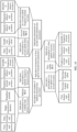
- FIG. 3 is a schematic flowchart of an uplink transmission method according to an embodiment of this application.
- the uplink transmission method may be applied to uplink cooperative communication between the first terminal and the network device through the second terminal, and/or direct uplink communication between the first terminal and the network device shown in FIG. 1 .
- the uplink transmission method includes the following steps.
- a network device sends first scheduling information to a first terminal and a second terminal.
- the first terminal and the second terminal receive the first scheduling information from the network device.
- the network device may send the first scheduling information to the first terminal and the second terminal through a physical downlink control channel (physical downlink control channel, PDCCH).
- PDCCH physical downlink control channel
- the first scheduling information may be carried in downlink control information (downlink control information, DCI) of the PDCCH.
- FIG. 4 is a schematic diagram 1 of DCI carrying first scheduling information according to an embodiment of this application. The following describes content of the first scheduling information in detail with reference to FIG. 4 .
- the first scheduling information includes indication information of a sidelink transmission parameter and indication information of a first uplink transmission parameter
- the sidelink transmission parameter is used by the first terminal to send first data to the second terminal
- the first uplink transmission parameter is used by the second terminal to send the first data to the network device.
- the sidelink transmission parameter may include indication information of a sidelink time domain resource, and the sidelink time domain resource is used by the first terminal to send the first data to the second terminal; and the first uplink transmission parameter may include indication information of a first uplink time domain resource, and the first uplink time domain resource is used by the second terminal to send the first data to the network device.
- the indication information of the sidelink time domain resource may include one or more of a time domain start position, a time domain end position, single-transmission duration, and a repetition quantity that are of the sidelink resource.
- the time domain start position of the sidelink resource is a start position of the first transmission in one or more transmissions corresponding to the repetition quantity, for example, a slot in which the first symbol in the first transmission is located.
- the time domain end position of the sidelink resource is an end position of the last transmission in the one or more transmissions corresponding to the repetition quantity, for example, a slot (slot) in which the last symbol in the last transmission is located.
- the repetition quantity is a positive integer. Alternatively, the repetition quantity may not be configured, and in this case, it may be considered by default that there is a single transmission.
- the indication information of the sidelink time domain resource is not specifically limited in this embodiment of this application, provided that the time domain position of the sidelink resource can be uniquely determined.
- the indication information of the sidelink time domain resource may include only the time domain start position, the single-transmission duration, and the repetition quantity that are of the sidelink resource, or include only the time domain end position, the single-transmission duration, and the repetition quantity.
- the indication information of the sidelink time domain resource may not include the repetition quantity.
- the indication information of the sidelink time domain resource may include only the time domain start position and the time domain end position that are of the sidelink resource, or include only the time domain start position and the single-transmission duration that are of the sidelink resource, or include only the time domain end position and the single-transmission duration that are of the sidelink resource.
- the indication information of the first uplink time domain resource may include a time domain start position of the first uplink resource or a time domain offset between the first uplink resource and the sidelink resource.
- the indication information of the first uplink time domain resource may further include a time domain end position, transmission duration, and the like that are of the first uplink resource.
- the time domain start position of the first uplink resource may include a symbol number of a time domain start symbol of the first uplink resource and/or a slot number of a slot in which the time domain start symbol is located.
- symbol may be an orthogonal frequency division multiplexing (orthogonal frequency division multiplexing, OFDM) symbol
- the "slot (slot)” may be one of a full slot (full slot), a short slot (short slot), or a mini slot (mini slot).
- the time domain offset between the first uplink resource and the sidelink resource may include one of the following: a first time domain offset and a third time domain offset.
- the first time domain offset may be a time domain offset between the time domain start position of the first uplink resource and the time domain end position of the sidelink resource; and the third time domain offset may be a time domain offset between the time domain start position of the first uplink resource and the time domain start position of the sidelink resource.
- content of the indication information of the first uplink time domain resource is not specifically limited in this embodiment of this application, provided that it can be ensured that the time domain start position of the first uplink resource is after the time domain end position of the sidelink resource, to be specific, a time domain position relationship between the first uplink resource and the sidelink resource can ensure that the second terminal has sufficient processing time to complete the following operations: receiving the first data from the first terminal, demodulating and decoding the first data to obtain original information of the first data, re-modulating and re-encoding the original information, and forwarding the first data to the network device.
- the indication information of the first uplink time domain resource may include only the time domain start position of the first uplink resource.
- the indication information of the first uplink time domain resource may include only the first time domain offset.
- the indication information of the first uplink time domain resource may include only the third time domain offset.
- the following describes in detail how to determine the time domain start position of the first uplink resource when the indication information of the first uplink time domain resource does not include the time domain start position of the first uplink resource.
- FIG. 5 is a schematic diagram 1 of a time domain position relationship between a sidelink resource and a first uplink resource according to an embodiment of this application.
- the indication information of the sidelink time domain resource may include one or more of a time domain end position t1, a time domain start position t2, single-transmission duration L, and a repetition quantity K that are of the sidelink resource.
- SL-i is a sidelink resource occupied by an i th transmission, where i is a positive integer, and a value range of i is 1 to K.
- the repetition quantity K is a quantity of sidelink transmissions or an index value a one-to-one correspondence with the quantity of sidelink transmissions.
- the single-transmission duration L is duration of a single transmission in the K sidelink transmissions, for example, may be a quantity of consecutive symbols included in the single transmission.
- the time domain start position t2 is a time domain start position of the first transmission in K repeated transmissions, for example, may include a symbol number of a time domain start symbol of the first transmission and/or a slot number of a slot in which the time domain start symbol is located.
- the time domain end position t1 is an end position of the last transmission in the K repeated transmissions, for example, may include a symbol number of a time domain end symbol of the last transmission and/or a slot number of a slot in which the time domain end symbol is located.
- the indication information of the first uplink time domain resource may include one or more of the following: a time domain start position t3 of the first uplink resource, a first time domain offset T1 between the time domain start position t3 of the first uplink resource and the time domain end position t1 of the sidelink resource, and a third time domain offset T3 between the time domain start position t3 of the first uplink time domain resource and the time domain start position t2 of the sidelink resource.
- the time domain start position of the first uplink resource may include a symbol number of a time domain start symbol of the first uplink resource and/or a slot number of a slot in which the time domain start symbol is located.
- FIG. 6 is a schematic diagram 2 of a time domain position relationship between a sidelink resource and a first uplink resource according to an embodiment of this application.
- the indication information of the sidelink time domain resource may not include the repetition quantity K.
- the time domain start position of the first uplink resource may be determined in one of the following manner 1 to manner 3. Details are described below with reference to FIG. 5 and FIG. 6 .
- the total sidelink transmission duration is a product of the repetition quantity K and the single-transmission duration L, that is, K*L.
- FIG. 7 is a schematic diagram 2 of DCI carrying first scheduling information according to an embodiment of this application. The following further describes content of the first scheduling information in detail with reference to FIG. 7 .
- the first scheduling information may further include indication information of a second uplink transmission parameter, and the second uplink transmission parameter is used by the first terminal to send second data to the network device.
- the second uplink transmission parameter may include indication information of a second uplink time domain resource, and the second uplink time domain resource is used by the first terminal to send the second data to the network device.
- the indication information of the second uplink time domain resource may include a time domain start position of the second uplink resource or a time domain offset between the second uplink resource and the sidelink resource.
- the indication information of the second uplink time domain resource may include a time domain end position, transmission duration, and the like that are of the second uplink resource.
- the time domain start position of the second uplink resource may include a symbol number of a time domain start symbol (symbol) of the second uplink resource and/or a slot number of a slot in which the time domain start symbol is located.
- the time domain offset between the second uplink resource and the sidelink resource may include one of the following: a second time domain offset and a fourth time domain offset.
- the second time domain offset may be a time domain offset between the time domain start position of the second uplink resource and the time domain end position of the sidelink resource; and the fourth time domain offset may be a time domain offset between the time domain start position of the second uplink resource and the time domain start position of the sidelink resource.
- the indication information of the second uplink time domain resource is not specifically limited in this embodiment of this application, provided that the time domain start position of the second uplink resource can be uniquely determined, and it is ensured that the time domain start position of the second uplink resource is after the time domain end position of the sidelink resource.
- the indication information of the second uplink time domain resource may include only the time domain start position of the second uplink resource.
- the indication information of the sidelink time domain resource includes the time domain start position, the single-transmission duration, and the repetition quantity that are of the sidelink resource
- the indication information of the second uplink time domain resource may include only the second time domain offset.
- the indication information of the sidelink time domain resource includes the time domain start position of the sidelink resource
- the indication information of the second uplink time domain resource may include only the fourth time domain offset.
- the first terminal may send, with the assistance of the second terminal, the first data to the network device on the sidelink resource and the first uplink resource, and send the first data to the network device on the second uplink resource, so that the network device performs combined decoding on the first data received on the first uplink resource and the first data received on the second uplink resource, to improve a decoding success rate, and further improve uplink data transmission reliability.
- a time domain position relationship between the second uplink resource and the first uplink resource further needs to ensure that a time deviation between time at which the first data forwarded by the second terminal on the first uplink resource arrives at the network device and time at which the first data sent by the first terminal on the second uplink resource arrives at the network device is less than or equal to an arrival time deviation threshold, to reduce a quantity of storage resources used by the network device to buffer the first data.
- the following describes in detail a method for determining the time domain start position of the second uplink resource.
- the indication information of the second uplink time domain resource may include one or more of the following: a time domain start position t4 of the second uplink resource, a second time domain offset T2 between the time domain start position t4 of the second uplink resource and the time domain end position t1 of the sidelink resource, and a fourth time domain offset T4 between the time domain start position t4 of the second uplink time domain resource and the time domain start position t2 of the sidelink resource.
- the time domain start position of the second uplink resource may include a symbol number of a time domain start symbol of the second uplink resource and/or a slot number of a slot in which the time domain start symbol is located.
- the time domain start position of the second uplink resource may be determined in the following manner 4 to manner 6. Details are described below.
- the total sidelink transmission duration is a product of the repetition quantity K and the single-transmission duration L, that is, K*L.
- the total sidelink transmission duration is the single-transmission duration L.
- the indication information of the first uplink time domain resource and the indication information of the second uplink time domain resource may be completely the same, partially the same, or completely different. Same content in the indication information of the first uplink time domain resource and the indication information of the second uplink time domain resource may be indicated by a same indication field in the first scheduling information, to reduce signaling overheads.
- FIG. 10 to FIG. 12 are respectively schematic diagrams 3 to 5 of DCI carrying first scheduling information according to embodiments of this application. The following further describes content of the first scheduling information in detail with reference to FIG. 7 to FIG. 9 and FIG. 10 to FIG. 12 .
- T1 and T2 may occupy a same indication field, to reduce signaling overheads.
- T2 may be carried in the indication information of the second uplink time domain resource, and T1 does not need to be carried in the indication information of the first uplink time domain resource.
- T3 and T4 may occupy a same indication field, to reduce signaling overheads.
- T4 may be carried in the indication information of the second uplink time domain resource, and T3 does not need to be carried in the indication information of the first uplink time domain resource.
- the indication information of the first uplink time domain resource and the indication information of the second uplink time domain resource are completely the same, only one of the indication information of the first uplink time domain resource and the indication information of the second uplink time domain resource needs to be transmitted.
- the indication information of the first uplink transmission parameter includes the indication information of the first uplink time domain resource
- the indication information of the second uplink transmission parameter does not include indication information of the second uplink time domain resource.
- the sidelink transmission parameter may further include a sidelink modulation and coding scheme (modulation and coding scheme, MCS), the first uplink transmission parameter may further include a first uplink MCS, and the second uplink transmission parameter may further include a second uplink MCS.
- MCS modulation and coding scheme
- the first uplink transmission parameter may further include a first uplink MCS
- the second uplink transmission parameter may further include a second uplink MCS.
- MCS modulation and coding scheme
- the first uplink MCS, and the second uplink MCS may be the same or may be different.
- the any two MCSs may occupy a same indication field in the first scheduling information, to further reduce signaling overheads.
- the first uplink MCS and the second uplink MCS may occupy a same indication field in the first scheduling information.
- FIG. 13 is a schematic diagram 6 of DCI carrying first scheduling information according to an embodiment of this application.
- the first uplink MCS and the second uplink MCS may occupy a same indication field in the first scheduling information, to further reduce signaling overheads.
- the first uplink MCS and the second uplink MCS are the same, only the first uplink MCS and the second uplink MCS need to be carried in a first uplink MCS indication field in the indication information of the first uplink transmission parameter, and the second uplink MCS does not need to be carried in the indication information of the second uplink transmission parameter.
- only the first uplink MCS and the second uplink MCS may be carried in a second uplink MCS indication field in the indication information of the second uplink transmission parameter, and the first uplink MCS does not need to be carried in a first uplink MCS indication field in the indication information of the first uplink transmission parameter.
- the sidelink transmission parameter may further include indication information of a sidelink frequency domain resource
- the first uplink transmission parameter may further include indication information of a first uplink frequency domain resource
- the first uplink frequency domain resource is used by the second terminal to send the first data to the network device
- the second uplink transmission parameter may further include indication information of a second uplink frequency domain resource
- the second uplink frequency domain resource is used by the first terminal to send the second data to the network device.
- the indication information of the first uplink frequency domain resource and the indication information of the second uplink frequency domain resource may be the same or may be different.
- the indication information of the first uplink frequency domain resource and the indication information of the second uplink frequency domain resource may occupy a same indication field in the first scheduling information, to further reduce signaling overheads.
- the indication information of each frequency domain resource may include one or more of a frequency domain start position, a frequency domain end position, and a quantity of frequency domain resources that are of each resource on a communication link.
- the frequency domain start position and the frequency domain end position that are of each resource may be represented by the following: a resource block (resource block, RB) index, a physical resource block (physical resource block, PRB), a sub-band (sub-band) index, a sub-channel (sub-channel) index, or the like.
- the quantity of frequency domain resources of each resource may include quantities of RBs, PRBs, sub-bands, and sub-channels included in each frequency domain resource.
- An implementation of the indication information of each frequency domain resource is not specifically limited in this embodiment of this application.
- the indication information of the first uplink frequency domain resource and the indication information of the second uplink frequency domain resource may be completely the same, partially the same, or completely different. Same content in the indication information of the first uplink frequency domain resource and the indication information of the second uplink frequency domain resource may also occupy a same indication field in the first scheduling information, to further reduce signaling overheads.
- a transmission scheme used when the indication information of the first uplink frequency domain resource and the indication information of the second uplink frequency domain resource are partially the same refer to the transmission scheme, shown in FIG. 10 or FIG. 11 , used when the indication information of the first uplink time domain resource and the indication information of the second uplink time domain resource are partially the same. Details are not described herein again.
- FIG. 14 is a schematic diagram 7 of DCI carrying first scheduling information according to an embodiment of this application.
- the indication information of the first uplink frequency domain resource and the indication information of the second uplink frequency domain resource are completely the same, the indication information of the first uplink frequency domain resource and the indication information of the second uplink frequency domain resource may occupy a same indication field in the first scheduling information. As shown in FIG. 7 , assuming that the indication information of the first uplink frequency domain resource and the indication information of the second uplink frequency domain resource are completely the same, the indication information of the first uplink frequency domain resource and the indication information of the second uplink frequency domain resource may occupy a same indication field in the first scheduling information. As shown in FIG.
- the indication information of the first uplink frequency domain resource and the indication information of the second uplink frequency domain resource are completely the same, only the indication information of the first uplink frequency domain resource and the indication information of the second uplink frequency domain resource need to be carried in an indication field of the indication information of the first uplink frequency domain resource in the indication information of the first uplink transmission parameter, and the indication information of the second uplink frequency domain resource does not need to be carried in an indication field of the indication information of the second uplink frequency domain resource in the indication information of the second uplink transmission parameter.
- the indication information of the first uplink frequency domain resource and the indication information of the second uplink frequency domain resource may be carried in an indication field of the indication information of the second uplink frequency domain resource in the indication information of the second uplink transmission parameter, and the indication information of the first uplink frequency domain resource does not need to be carried in an indication field of the indication information of the first uplink frequency domain resource in the indication information of the first uplink transmission parameter.
- the indication information of the first uplink transmission parameter and the indication information of the second uplink transmission parameter may occupy a same indication field in the first scheduling information.
- FIG. 15 is a schematic diagram 8 of DCI carrying first scheduling information according to an embodiment of this application.
- the indication information of the first uplink transmission parameter and the indication information of the second uplink transmission parameter occupy only an indication field of the indication information of the first uplink transmission parameter in the first scheduling information. In other words, only one of the indication information of the first uplink transmission parameter and the indication information of the second uplink transmission parameter needs to be transmitted.
- the first terminal may send an uplink transmission request and a buffer status report (buffer status report, BSR) to the network device.
- BSR buffer status report
- the BSR carries a data volume of to-be-transmitted uplink data of the first terminal, for example, a data volume of to-be-sent data in a media access control (media access control, MAC) layer buffer (buffer) of the first terminal.
- media access control media access control, MAC
- the network device may determine content of the first scheduling information based on information such as the data volume, a service type of the first terminal, a quantity of idle resources in the second uplink resource between the first terminal and the network device, channel quality of a second uplink channel between the first terminal and the network device, a quantity of idle resources in the sidelink resource between the first terminal and the second terminal, channel quality of a sidelink channel between the first terminal and the second terminal, a quantity of idle resources in the first uplink resource between one or more second terminals and the network device, and channel quality of a first uplink channel between the one or more second terminals and the network device, and send the content of the first scheduling information to the first terminal and the one or more second terminals.
- information such as the data volume, a service type of the first terminal, a quantity of idle resources in the second uplink resource between the first terminal and the network device, channel quality of a second uplink channel between the first terminal and the network device, a quantity of idle resources in the sidelink resource between the first terminal and the second terminal, channel quality
- the first terminal, the second terminal, and the network device may complete transmission of the to-be-transmitted uplink data of the first terminal based on the first scheduling information, that is, perform the following S302 and S303.
- S302 The first terminal sends the first data to the second terminal.
- the second terminal receives the first data from the first terminal.
- the first terminal may send sidelink control information (sidelink control information, SCI) to the second terminal on a physical sidelink control channel (physical sidelink control channel, PSCCH).
- SCI sidelink control information
- PSCCH physical sidelink control channel
- the second terminal receives the SCI from the first terminal on the PSCCH.
- the first terminal may send the first data to the second terminal on a physical sidelink shared channel (physical sidelink shared channel, PSSCH).
- PSSCH physical sidelink shared channel
- the second terminal receives the first data from the first terminal on the PSSCH.
- the SCI carries sidelink demodulation information of the first data, such as a sidelink MCS and a time-frequency resource carrying a sidelink demodulation reference signal (demodulation reference signal, DMRS), so that the second terminal parses the PSSCH based on the sidelink demodulation information, to restore the original information of the first data, that is, original data before the first data is encoded and modulated.
- sidelink demodulation information of the first data such as a sidelink MCS and a time-frequency resource carrying a sidelink demodulation reference signal (demodulation reference signal, DMRS)
- the second terminal may send feedback information to the first terminal.
- the feedback information is used by the first terminal to stop sending the first data, to reduce resource overheads between the first terminal and the second terminal, and reduce power consumption of the first terminal and the second terminal.
- the second terminal may send an acknowledgment (acknowledgement, ACK) indication bit (bit) to the first terminal on a physical sidelink feedback channel (physical sidelink feedback channel, PSFCH).
- PSFCH physical sidelink feedback channel
- S303 The second terminal sends the first data to the network device.
- the network device receives the first data from the second terminal.
- the second terminal may re-encode and re-modulate the original information of the first data, and send the re-encoded and re-modulated first data to the network device on the first uplink resource.
- the second terminal may forward the first data of the first terminal to the network device in a decode-and-forward manner.
- the second terminal may also directly forward, to the network device in a manner of increasing transmit power, a radio signal of the PSSCH that carries the first data, that is, forward the first data to the network device in an amplify-and-forward manner.
- the network device may demodulate and decode the received first data.
- the radio signal that carries the first data may be demodulated and decoded based on the first uplink MCS or the sidelink MCS.
- the first terminal sends the first data to the network device through the second terminal in FIG. 1 , and sends third data to the network device by using another terminal such as a third terminal (not shown in FIG. 1 ).
- the network device may perform combined decoding on the first data and the third data, to improve decoding performance of uplink transmission. It is easily understood that if the first data and the third data are different data, an uplink throughput between the first terminal and the network device can be improved.
- the first terminal may alternatively directly send the second data to the network device on the second uplink resource.
- the uplink transmission method shown in FIG. 3 may further include S304.
- S304 The first terminal sends the second data to the network device.
- the network device receives the second data from the first terminal.
- the second data may be the same as the first data, or may be different from the first data. Specifically, when a channel is in a good condition, the second data may be different from the first data, to improve an uplink throughput between the first terminal and the network device, and improve communication efficiency. Alternatively, optionally, when a channel is in a poor condition, the second data may be the same as the first data, that is, the first data and the second data both are data obtained by encoding and modulating same original data by using a same MCS.
- the network device may perform combined decoding on the first uplink signal carrying the first data and the second uplink signal carrying the second data, to improve decoding performance and a success rate, and improve reliability of uplink data transmission between the first terminal and the network device.
- the network device can indicate, in one piece of scheduling information, both the sidelink resource and the first uplink resource that are required for the uplink cooperative transmission, to improve resource scheduling efficiency.
- a problem that the sidelink resource and/or the uplink resource are scheduled for a plurality of times because the independently scheduled sidelink resource and uplink resource cannot adapt to the uplink cooperative transmission can be avoided. This can reduce an uplink cooperative transmission delay, and improve uplink cooperative transmission efficiency.
- the uplink transmission method provided in embodiments of this application is described above in detail with reference to FIG. 3 to FIG. 15 .
- the following describes in detail another communication apparatus in an embodiment of this application with reference to FIG. 16 .
- FIG. 16 is a schematic diagram 2 of a structure of a communication apparatus according to an embodiment of this application.
- the communication apparatus may be applied to the communication system shown in FIG. 1 , and perform a function of the network device in the uplink transmission method shown in FIG. 3 .
- FIG. 16 shows only main components of the communication apparatus 1600.
- the communication apparatus 1600 includes a receiving module (or receiving unit) 1601 and a sending module (or sending unit) 1602.
- the sending module 1602 is configured to send first scheduling information to a first terminal and a second terminal.
- the first scheduling information includes indication information of a sidelink transmission parameter and indication information of a first uplink transmission parameter.
- the sidelink transmission parameter is used by the first terminal to send first data to the second terminal.
- the first uplink transmission parameter is used by the second terminal to send the first data to the network device.
- the receiving module 1601 is configured to receive the first data from the second terminal.
- the first scheduling information may further include indication information of a second uplink transmission parameter, and the second uplink transmission parameter is used by the first terminal to send second data to the network device.
- the receiving module 1601 is further configured to receive the second data from the first terminal.
- the communication apparatus 1600 may also be applied to the communication system shown in FIG. 1 , and perform a function of the first terminal in the uplink transmission method shown in FIG. 3 .
- the receiving module 1601 is configured to receive first scheduling information from the network device.
- the first scheduling information includes indication information of a sidelink transmission parameter and indication information of a first uplink transmission parameter.
- the sidelink transmission parameter is used by the first terminal to send first data to the second terminal.
- the first uplink transmission parameter is used by the second terminal to send the first data to the network device.
- the sending module 1602 is configured to send the first data to the second terminal.
- the first scheduling information may further include indication information of a second uplink transmission parameter, and the second uplink transmission parameter is used by the first terminal to send second data to the network device.
- the sending module 1602 is further configured to send the second data to the network device.
- the communication apparatus 1600 may also be applied to the communication system shown in FIG. 1 , and perform a function of the second terminal in the uplink transmission method shown in FIG. 3 .
- the receiving module 1601 is configured to receive first scheduling information from the network device.
- the first scheduling information includes indication information of a sidelink transmission parameter and indication information of a first uplink transmission parameter.
- the sidelink transmission parameter is used by the first terminal to send first data to the second terminal.
- the first uplink transmission parameter is used by the second terminal to send the first data to the network device.
- the receiving module 1601 is further configured to receive the first data from the first terminal.
- the sending module 1602 is configured to send the first data to the network device.
- the first scheduling information may further include indication information of a second uplink transmission parameter, and the second uplink transmission parameter is used by the first terminal to send second data to the network device.
- the sidelink transmission parameter may include indication information of a sidelink time domain resource, and the sidelink time domain resource is used by the first terminal to send the first data to the second terminal.
- the first uplink transmission parameter may include indication information of a first uplink time domain resource
- the first uplink time domain resource is used by the second terminal to send the first data to the network device
- the second uplink transmission parameter may include indication information of a second uplink time domain resource
- the second uplink time domain resource is used by the first terminal to send the second data to the network device.
- the indication information of the sidelink time domain resource may include one or more of a time domain start position, a time domain end position, single-transmission duration, and a repetition quantity that are of the sidelink resource.
- the time domain start position of the sidelink resource is a start position of the first transmission in one or more transmissions corresponding to the repetition quantity, for example, a slot in which the first symbol in the first transmission is located.
- the time domain end position of the sidelink resource is an end position of the last transmission in one or more transmissions corresponding to the repetition quantity, for example, a slot (slot) in which the last symbol in the last transmission is located.
- the repetition quantity is a positive integer. Alternatively, the repetition quantity may not be configured, and in this case, single transmission is used by default.
- the indication information of the first uplink time domain resource may include a time domain start position of the first uplink resource, or a time domain offset between a time domain start position of the first uplink resource and the time domain start position or the time domain end position of the sidelink resource.
- the time domain start position of the first uplink resource may be one or both of a start symbol (symbol) of the first uplink resource in time domain and a slot in which the start symbol is located.
- the time domain offset between the time domain start position of the first uplink resource and the time domain start position or the time domain end position of the sidelink resource may include one of the following: a first time domain offset and a third time domain offset.
- the first time domain offset may be a time domain offset between the time domain start position of the first uplink resource and the time domain end position of the sidelink resource; and the third time domain offset may be a time domain offset between the time domain start position of the first uplink resource and the time domain start position of the sidelink resource.
- the time domain start position of the first uplink resource may be directly configured, or may be determined in the following manner 1 to manner 3. Details are described below.
- the time domain start position of the first uplink resource is: a sum of the time domain start position of the sidelink resource and the third time domain offset.
- the time domain start position of the first uplink resource is: a sum of the time domain end position of the sidelink resource and the first time domain offset.
- the time domain start position of the first uplink resource is: a sum of the time domain start position of the sidelink resource, total sidelink transmission duration, and the first time domain offset.
- the indication information of the second uplink time domain resource may include a time domain start position of the second uplink resource, or a time domain offset between a time domain start position of the second uplink resource and the time domain start position or the time domain end position of the sidelink resource.
- the time domain start position of the second uplink resource may be one or both of a start symbol of the second uplink resource in time domain and a slot in which the start symbol is located.
- the time domain offset between the time domain start position of the second uplink resource and the time domain start position or the time domain end position of the sidelink resource may include one of the following: a second time domain offset and a fourth time domain offset.
- the second time domain offset may be a time domain offset between the time domain start position of the second uplink resource and the time domain end position of the sidelink resource; and the fourth time domain offset may be a time domain offset between the time domain start position of the second uplink resource and the time domain start position of the sidelink resource.
- the time domain start position of the second uplink resource may be directly configured, or may be determined in the following manner 4 to manner 6. Details are described below.
- the time domain start position of the second uplink resource is: a sum of the time domain start position of the sidelink resource and the fourth time domain offset.
- the time domain start position of the second uplink resource is: a sum of the time domain end position of the sidelink resource and the second time domain offset.
- the time domain start position of the second uplink resource is: a sum of the time domain start position of the sidelink resource, total sidelink transmission duration, and the second time domain offset.
- the total sidelink transmission duration is single-transmission duration.
- the total sidelink transmission duration is a product of the single-transmission duration and the repetition quantity.
- the first uplink transmission parameter may further include a first uplink MCS
- the second uplink transmission parameter may further include a second uplink MCS.
- the first uplink MCS and the second uplink MCS are indicated by a same indication field in the first scheduling information.
- the first uplink MCS and the second uplink MCS may occupy a same indication field in the first scheduling information, to reduce signaling overheads.
- the first uplink transmission parameter may further include indication information of a first uplink frequency domain resource
- the first uplink frequency domain resource is used by the second terminal to send the first data to the network device
- the second uplink transmission parameter may further include indication information of a second uplink frequency domain resource
- the second uplink frequency domain resource is used by the first terminal to send the second data to the network device.
- the indication information of the first uplink frequency domain resource and the indication information of the second uplink frequency domain resource are indicated by a same indication field in the first scheduling information.
- the indication information of the first uplink frequency domain resource and the indication information of the second uplink frequency domain resource may occupy a same indication field in the first scheduling information, to further reduce signaling overheads.
- the second data may be different from the first data, or may be the same as the first data. This is not limited in this embodiment of this application.
- the communication apparatus 1600 shown in FIG. 16 may further include a processing module and/or a storage module (not shown in FIG. 6 ).
- the processing module may control the sending module 1602 and the receiving module 1601 to complete the uplink transmission method in the foregoing method embodiment.
- the storage module stores a program or instructions. When the processing module executes the program or the instructions, the communication apparatus 1600 shown in FIG. 6 is enabled to perform the uplink transmission method in the foregoing method embodiment.
- the communication apparatus 1600 shown in FIG. 16 may be the first terminal, the second terminal, or the network device shown in FIG. 1 , or the communication apparatus 200 shown in FIG. 2 , or may be a component or a combined component disposed in the first terminal, the second terminal, or the network device, such as a chip or a chip system. This is not limited in this embodiment of this application.
- the receiving module 1601 and the sending module 1602 may be respectively a receiver and a transmitter in the terminal device or the network device, or the receiving module 1601 and the sending module 1602 may be combined into one component, for example, a transceiver having a receiving function and a sending function in the terminal device or the network device.
- the receiving module 1601, the sending module 1602, and the transceiver may include an antenna, a radio frequency circuit, and the like.
- the processing module in the communication apparatus 1600 shown in FIG. 16 may be a processor such as a central processing unit (central processing unit, CPU).
- the receiving module 1601 and the sending module 1602 may be radio frequency units, and the processing module may be a processor.
- the receiving module 1601 and the sending module 1602 may be an input/output interface of the chip system, and the processing module may be a processor in the chip system.
- An embodiment of this application provides a chip system.
- the chip system includes a processor and an input/output port.
- the processor is coupled to a memory including instructions, and is configured to control a communication apparatus installed with the chip system to implement the uplink transmission method according to the foregoing method embodiment.
- the memory may be a memory, for example, an internal cache, integrated in the chip system; or may be an external memory, for example, an external cache, that is located outside the chip system and has a signal connection to the chip system; or may include both an internal memory and an external memory.
- the memory is configured to store program instructions and data for implementing the uplink transmission method in the foregoing method embodiment.
- the chip system may include a chip, or may include a chip and another discrete component.
- An embodiment of this application provides a communication system.
- the system includes a network device and at least two terminal devices, for example, a first terminal and a second terminal.
- An embodiment of this application provides a computer-readable storage medium.
- the computer-readable storage medium stores computer instructions.
- the computer instructions When the computer instructions are run on a computer, the computer is enabled to perform the uplink transmission method in the foregoing method embodiment.
- An embodiment of this application provides a computer program product including instructions.
- the computer program product includes a computer program or the instructions.
- the computer program is run or the instructions are run on a computer, the computer is enabled to perform the uplink transmission method in the foregoing method embodiment.
- the processor in embodiments of this application may be a central processing unit (central processing unit, CPU), or may be another general-purpose processor, a digital signal processor (digital signal processor, DSP), an application-specific integrated circuit (application-specific integrated circuit, ASIC), a field programmable gate array (field programmable gate array, FPGA) or another programmable logic device, a discrete gate or a transistor logic device, a discrete hardware component, or the like.
- the general-purpose processor may be a microprocessor, or the processor may be any conventional processor or the like.
- the memory in embodiments of this application may be a volatile memory or a nonvolatile memory, or may include both a volatile memory and a nonvolatile memory.
- the nonvolatile memory may be a read-only memory (read-only memory, ROM), a programmable read-only memory (programmable ROM, PROM), an erasable programmable read-only memory (erasable PROM, EPROM), an electrically erasable programmable read-only memory (electrically EPROM, EEPROM), or a flash memory.
- the volatile memory may be a random access memory (random access memory, RAM) and is used as an external cache.
- random access memories in various forms are available, for example, a static random access memory (static RAM, SRAM), a dynamic random access memory (DRAM), a synchronous dynamic random access memory (synchronous DRAM, SDRAM), a double data rate synchronous dynamic random access memory (double data rate SDRAM, DDR SDRAM), an enhanced synchronous dynamic random access memory (enhanced SDRAM, ESDRAM), a synchlink dynamic random access memory (synchlink DRAM, SLDRAM), and a direct rambus random access memory (direct rambus RAM, DR RAM).
- static random access memory static random access memory
- DRAM dynamic random access memory
- SDRAM synchronous dynamic random access memory
- double data rate SDRAM double data rate SDRAM
- DDR SDRAM double data rate SDRAM
- ESDRAM enhanced synchronous dynamic random access memory
- synchlink dynamic random access memory synchlink dynamic random access memory
- direct rambus RAM direct rambus RAM, DR RAM
- All or some of the foregoing embodiments may be implemented by using software, hardware (for example, a circuit), firmware, or any combination thereof.
- the software is used for implementation, all or some of the foregoing embodiments may be implemented in a form of a computer program product.
- the computer program product includes one or more computer instructions or computer programs. When the program instructions or the computer programs are loaded and executed on a computer, the procedures or functions according to embodiments of this application are all or partially generated.
- the computer may be a general-purpose computer, a dedicated computer, a computer network, or another programmable apparatus.
- the computer instructions may be stored in a computer-readable storage medium or may be transmitted from a computer-readable storage medium to another computer-readable storage medium.
- the computer instructions may be transmitted from a website, computer, server, or data center to another website, computer, server, or data center in a wired (for example, infrared, radio, or microwave) manner.
- the computer-readable storage medium may be any usable medium accessible by a computer, or a data storage device, such as a server or a data center, integrating one or more usable media.
- the usable medium may be a magnetic medium (for example, a floppy disk, a hard disk, or a magnetic tape), an optical medium (for example, a DVD), or a semiconductor medium.
- the semiconductor medium may be a solid-state drive.
- At least one refers to one or more, and "a plurality of refers to two or more.
- the term "at least one (piece) of the following” or a similar expression thereof means any combination of these items, including any combination of one (piece) or a plurality (pieces).
- at least one (piece) of a, b, or c may indicate: a, b, c, a and b, a and c, b and c, or a, b, and c, where a, b, and c may be singular or plural.
- sequence numbers of the foregoing processes do not mean execution sequences in various embodiments of this application.
- the execution sequences of the processes should be determined based on functions and internal logic of the processes, but should not be construed as any limitation on the implementation processes in embodiments of this application.
- the disclosed system, apparatus, and method may be implemented in other manners.
- the described apparatus embodiments are merely examples.
- division into the units is merely logical function division and may be other division during actual implementation.
- a plurality of units or components may be combined or integrated into another system, or some features may be ignored or may not be performed.
- the displayed or discussed mutual couplings or direct couplings or communication connections may be implemented through some interfaces.
- the indirect couplings or communication connections between the apparatuses or units may be implemented in electrical, mechanical, or other forms.
- the units described as separate parts may or may not be physically separated, and parts displayed as units may or may not be physical units, that is, may be located in one position, or may be distributed on a plurality of network units. Some or all of the units may be selected based on actual requirements to achieve the objectives of the solutions of embodiments.
- functional units in embodiments of this application may be integrated into one processing unit, or each of the units may exist alone physically, or two or more units are integrated into one unit.
- the functions When the functions are implemented in the form of a software functional unit and sold or used as an independent product, the functions may be stored in a computer-readable storage medium. Based on such an understanding, the technical solutions of this application essentially, or the part contributing to a current technology, or some of the technical solutions may be implemented in a form of a software product.
- the computer software product is stored in a storage medium, and includes several instructions for instructing a computer device (which may be a personal computer, a server, a network device, or the like) to perform all or a part of the steps of the methods described in embodiments of this application.
- the foregoing storage medium includes any medium that can store program code, such as a USB flash drive, a removable hard disk, a read-only memory (read-only memory, ROM), a random access memory (random access memory, RAM), a magnetic disk, or an optical disc.
- program code such as a USB flash drive, a removable hard disk, a read-only memory (read-only memory, ROM), a random access memory (random access memory, RAM), a magnetic disk, or an optical disc.
Landscapes
- Engineering & Computer Science (AREA)
- Computer Networks & Wireless Communication (AREA)
- Signal Processing (AREA)
- Mobile Radio Communication Systems (AREA)
Claims (16)
- Uplink-Übertragungsverfahren, das umfasst:Senden (S301), durch eine Netzwerkvorrichtung, von ersten Planungsinformationen an ein erstes Endgerät und ein zweites Endgerät, wobei die ersten Planungsinformationen Anzeigeinformationen eines Sidelink-Übertragungsparameters und Anzeigeinformationen eines ersten Uplink-Übertragungsparameters umfassen, wobei der Sidelink-Übertragungsparameter durch das erste Endgerät verwendet wird, um erste Daten an das zweite Endgerät zu senden, und der erste Uplink-Übertragungsparameter durch das zweite Endgerät verwendet wird, um die ersten Daten an die Netzwerkvorrichtung zu senden; undEmpfangen (S303), durch die Netzwerkvorrichtung, der ersten Daten von dem zweiten Endgerät.
- Uplink-Übertragungsverfahren nach Anspruch 1, wobei die ersten Planungsinformationen ferner Anzeigeinformationen eines zweiten Uplink-Übertragungsparameters umfassen und der zweite Uplink-Übertragungsparameter durch das erste Endgerät verwendet wird, um zweite Daten an die Netzwerkvorrichtung zu senden; und
das Uplink-Übertragungsverfahren ferner umfasst:
Empfangen (S304), durch die Netzwerkvorrichtung, der zweiten Daten von dem ersten Endgerät. - Uplink-Übertragungsverfahren nach Anspruch 2, wobei der Sidelink-Übertragungsparameter Anzeigeinformationen einer Sidelink-Zeitbereichsressource umfasst und die Sidelink-Zeitbereichsressource durch das erste Endgerät verwendet wird, um die ersten Daten an das zweite Endgerät zu senden;der erste Uplink-Übertragungsparameter Anzeigeinformationen einer ersten Uplink-Zeitbereichsressource umfasst und die erste Uplink-Zeitbereichsressource durch das zweite Endgerät verwendet wird, um die ersten Daten an die Netzwerkvorrichtung zu senden; undder zweite Uplink-Übertragungsparameter Anzeigeinformationen einer zweiten Uplink-Zeitbereichsressource umfasst und die zweite Uplink-Zeitbereichsressource durch das erste Endgerät verwendet wird, um die zweiten Daten an die Netzwerkvorrichtung zu senden.
- Uplink-Übertragungsverfahren nach Anspruch 3, wobei die Anzeigeinformationen der Sidelink-Zeitbereichsressource eine Zeitbereichsstartposition, eine Zeitbereichsendposition, eine Einzelübertragungsdauer und eine Wiederholungsmenge, die zu der Sidelink-Ressource gehören, umfassen, wobei die Anzeigeinformationen der ersten Uplink-Zeitbereichsressource einen ersten Zeitbereichsversatz umfassen und der erste Zeitbereichsversatz ein Zeitbereichsversatz zwischen einer Zeitbereichsstartposition der ersten Uplink-Ressource und der Zeitbereichsendposition der Sidelink-Ressource ist.
- Uplink-Übertragungsverfahren nach Anspruch 4, wobei die Zeitbereichsstartposition der ersten Uplink-Ressource ist: eine Summe der Zeitbereichsstartposition der Sidelink-Ressource, ein Erzeugnis der Einzelübertragungsdauer und der Wiederholungsmenge und der erste Zeitbereichsversatz.
- Uplink-Übertragungsverfahren, das umfasst:Empfangen (S301), durch ein erstes Endgerät, von ersten Planungsinformationen von einer Netzwerkvorrichtung, wobei die ersten Planungsinformationen Anzeigeinformationen eines Sidelink-Übertragungsparameters und Anzeigeinformationen eines ersten Uplink-Übertragungsparameters umfassen, wobei der Sidelink-Übertragungsparameter durch das erste Endgerät verwendet wird, um erste Daten an ein zweites Endgerät zu senden, und der erste Uplink-Übertragungsparameter durch das zweite Endgerät verwendet wird, um die ersten Daten an die Netzwerkvorrichtung zu senden; undSenden (S302), durch das erste Endgerät, der ersten Daten an das zweite Endgerät.
- Uplink-Übertragungsverfahren nach Anspruch 6, wobei die ersten Planungsinformationen ferner Anzeigeinformationen eines zweiten Uplink-Übertragungsparameters umfassen und der zweite Uplink-Übertragungsparameter durch das erste Endgerät verwendet wird, um zweite Daten an die Netzwerkvorrichtung zu senden; und
das Uplink-Übertragungsverfahren ferner umfasst:
Senden (S304), durch das erste Endgerät, der zweiten Daten an die Netzwerkvorrichtung. - Uplink-Übertragungsverfahren nach Anspruch 7, wobei der Sidelink-Übertragungsparameter Anzeigeinformationen einer Sidelink-Zeitbereichsressource umfasst und die Sidelink-Zeitbereichsressource durch das erste Endgerät verwendet wird, um die ersten Daten an das zweite Endgerät zu senden;der erste Uplink-Übertragungsparameter Anzeigeinformationen einer ersten Uplink-Zeitbereichsressource umfasst und die erste Uplink-Zeitbereichsressource durch das zweite Endgerät verwendet wird, um die ersten Daten an die Netzwerkvorrichtung zu senden; undder zweite Uplink-Übertragungsparameter Anzeigeinformationen einer zweiten Uplink-Zeitbereichsressource umfasst und die zweite Uplink-Zeitbereichsressource durch das erste Endgerät verwendet wird, um die zweiten Daten an die Netzwerkvorrichtung zu senden.
- Uplink-Übertragungsverfahren nach Anspruch 8, wobei die Anzeigeinformationen der Sidelink-Zeitbereichsressource eine Zeitbereichsstartposition, eine Zeitbereichsendposition, eine Einzelübertragungsdauer und eine Wiederholungsmenge, die zu der Sidelink-Ressource gehören, umfassen, wobei die Anzeigeinformationen der ersten Uplink-Zeitbereichsressource einen ersten Zeitbereichsversatz umfassen und der erste Zeitbereichsversatz ein Zeitbereichsversatz zwischen einer Zeitbereichsstartposition der ersten Uplink-Ressource und der Zeitbereichsendposition der Sidelink-Ressource ist.
- Uplink-Übertragungsverfahren nach Anspruch 9, wobei die Zeitbereichsstartposition der ersten Uplink-Ressource ist: eine Summe der Zeitbereichsstartposition der Sidelink-Ressource, ein Erzeugnis der Einzelübertragungsdauer und der Wiederholungsmenge und der erste Zeitbereichsversatz.
- Uplink-Übertragungsverfahren, das umfasst:Empfangen (S301), durch ein zweites Endgerät, von ersten Planungsinformationen von einer Netzwerkvorrichtung, wobei die ersten Planungsinformationen Anzeigeinformationen eines Sidelink-Übertragungsparameters und Anzeigeinformationen eines ersten Uplink-Übertragungsparameters umfassen, wobei der Sidelink-Übertragungsparameter durch ein erstes Endgerät verwendet wird, um erste Daten an das zweite Endgerät zu senden, und der erste Uplink-Übertragungsparameter durch das zweite Endgerät verwendet wird, um die ersten Daten an die Netzwerkvorrichtung zu senden;Empfangen (S302), durch das zweite Endgerät, der ersten Daten von dem ersten Endgerät; undSenden (S303), durch das zweite Endgerät, der ersten Daten an die Netzwerkvorrichtung.
- Uplink-Übertragungsverfahren nach Anspruch 11, wobei die ersten Planungsinformationen ferner Anzeigeinformationen eines zweiten Uplink-Übertragungsparameters umfassen und der zweite Uplink-Übertragungsparameter durch das erste Endgerät verwendet wird, um zweite Daten an die Netzwerkvorrichtung zu senden.
- Uplink-Übertragungsverfahren nach Anspruch 12, wobei der Sidelink-Übertragungsparameter Anzeigeinformationen einer Sidelink-Zeitbereichsressource umfasst und die Sidelink-Zeitbereichsressource durch das erste Endgerät verwendet wird, um die ersten Daten an das zweite Endgerät zu senden;der erste Uplink-Übertragungsparameter Anzeigeinformationen einer ersten Uplink-Zeitbereichsressource umfasst und die erste Uplink-Zeitbereichsressource durch das zweite Endgerät verwendet wird, um die ersten Daten an die Netzwerkvorrichtung zu senden; undder zweite Uplink-Übertragungsparameter Anzeigeinformationen einer zweiten Uplink-Zeitbereichsressource umfasst und die zweite Uplink-Zeitbereichsressource durch das erste Endgerät verwendet wird, um die zweiten Daten an die Netzwerkvorrichtung zu senden.
- Uplink-Übertragungsverfahren nach Anspruch 13, wobei die Anzeigeinformationen der Sidelink-Zeitbereichsressource eine Zeitbereichsstartposition, eine Zeitbereichsendposition, eine Einzelübertragungsdauer und eine Wiederholungsmenge, die zu der Sidelink-Ressource gehören, umfassen, wobei die Anzeigeinformationen der ersten Uplink-Zeitbereichsressource einen ersten Zeitbereichsversatz umfassen und der erste Zeitbereichsversatz ein Zeitbereichsversatz zwischen einer Zeitbereichsstartposition der ersten Uplink-Ressource und der Zeitbereichsendposition der Sidelink-Ressource ist.
- Uplink-Übertragungsverfahren nach Anspruch 14, wobei die Zeitbereichsstartposition der ersten Uplink-Ressource ist: eine Summe der Zeitbereichsstartposition der Sidelink-Ressource, ein Erzeugnis der Einzelübertragungsdauer und der Wiederholungsmenge und der erste Zeitbereichsversatz.
- Kommunikationseinrichtung, wobei die Kommunikationseinrichtung konfiguriert ist, um das Verfahren nach einem der Ansprüche 1 bis 5 oder einem der Ansprüche 6 bis 10 oder einem der Ansprüche 11 bis 15 durchzuführen.
Applications Claiming Priority (1)
| Application Number | Priority Date | Filing Date | Title |
|---|---|---|---|
| PCT/CN2019/114878 WO2021081951A1 (zh) | 2019-10-31 | 2019-10-31 | 上行传输方法及通信装置 |
Publications (3)
| Publication Number | Publication Date |
|---|---|
| EP4044442A1 EP4044442A1 (de) | 2022-08-17 |
| EP4044442A4 EP4044442A4 (de) | 2022-10-19 |
| EP4044442B1 true EP4044442B1 (de) | 2023-09-13 |
Family
ID=75715755
Family Applications (1)
| Application Number | Title | Priority Date | Filing Date |
|---|---|---|---|
| EP19950579.3A Active EP4044442B1 (de) | 2019-10-31 | 2019-10-31 | Uplink-übertragungsverfahren und kommunikationsvorrichtung |
Country Status (4)
| Country | Link |
|---|---|
| US (1) | US12267825B2 (de) |
| EP (1) | EP4044442B1 (de) |
| CN (1) | CN114556793B (de) |
| WO (1) | WO2021081951A1 (de) |
Families Citing this family (5)
| Publication number | Priority date | Publication date | Assignee | Title |
|---|---|---|---|---|
| US11937277B2 (en) * | 2019-12-20 | 2024-03-19 | Qualcomm Incorporated | Concurrent sidelink and uplink transmission |
| US11889541B2 (en) | 2020-01-24 | 2024-01-30 | Qualcomm Incorporated | Superposition transmission of sidelink and uplink |
| CN117241397A (zh) * | 2022-06-02 | 2023-12-15 | 华为技术有限公司 | 数据传输的方法、装置和系统 |
| US12356388B2 (en) * | 2022-06-03 | 2025-07-08 | Qualcomm Incorporated | Network coding with user equipment cooperation |
| CN121283478A (zh) * | 2024-07-01 | 2026-01-06 | 华为技术有限公司 | 一种通信方法及装置 |
Family Cites Families (20)
| Publication number | Priority date | Publication date | Assignee | Title |
|---|---|---|---|---|
| KR102110214B1 (ko) * | 2012-04-26 | 2020-05-13 | 한국전자통신연구원 | 부분적 단말 제어 단말 대 단말 통신 방법 |
| KR101927366B1 (ko) * | 2014-03-30 | 2018-12-11 | 엘지전자 주식회사 | 단말 간 통신을 지원하는 무선 통신 시스템에서 하향링크 제어 정보 송수신 방법 및 이를 위한 장치 |
| KR102319182B1 (ko) * | 2014-05-09 | 2021-10-29 | 삼성전자 주식회사 | D2D(Device to Device)통신 단말의 통신 방법 및 장치 |
| KR102364064B1 (ko) * | 2014-05-09 | 2022-02-18 | 삼성전자 주식회사 | 장치 간 무선 통신 시스템에서 간섭 회피를 위한 장치 및 방법 |
| US10455587B2 (en) * | 2014-12-05 | 2019-10-22 | Lg Electronics Inc. | Method and apparatus for terminal to transmit and receive signal using sidelinks between devices |
| WO2016108554A1 (en) * | 2014-12-30 | 2016-07-07 | Lg Electronics Inc. | Method and apparatus for performing switching control between uplink and sidelink in wireless communication system |
| CN107306453B (zh) | 2016-04-25 | 2019-12-17 | 华为技术有限公司 | 一种生成传输块的方法和装置 |
| CN107770871B (zh) * | 2016-08-22 | 2021-09-14 | 华为技术有限公司 | 消息收发方法、终端设备和网络设备 |
| CN115002910A (zh) * | 2016-09-30 | 2022-09-02 | 北京三星通信技术研究有限公司 | 一种v2x通信中的发送资源确定方法和设备 |
| CN109964518B (zh) * | 2016-11-30 | 2020-12-18 | Oppo广东移动通信有限公司 | 传输信息的方法、终端设备、网络设备和计算机存储介质 |
| CN108512576A (zh) * | 2017-02-28 | 2018-09-07 | 华为技术有限公司 | 一种实现用户设备协作的方法及装置 |
| US10244522B2 (en) * | 2017-03-03 | 2019-03-26 | Qualcomm Incorporated | Signaling for multiplexing of low latency communication and sidelink communications |
| CN108738135B (zh) * | 2017-04-13 | 2019-12-24 | 华为技术有限公司 | 上行信息发送方法、接收方法和装置 |
| CN109600852B (zh) * | 2017-09-30 | 2021-11-19 | 华为技术有限公司 | 一种资源指示方法、通信装置及网络设备 |
| EP3841808B1 (de) * | 2018-08-24 | 2025-11-05 | Guangdong Oppo Mobile Telecommunications Corp., Ltd. | Datenübertragungsverfahren, -vorrichtung und -system |
| US11172492B2 (en) * | 2018-12-12 | 2021-11-09 | Apple Inc. | Power saving for pedestrian user equipment in vehicular communications systems |
| CN113972977B (zh) * | 2018-12-29 | 2024-06-14 | 北京小米移动软件有限公司 | 直连通信的数据传输方法、装置、设备及系统 |
| EP3989658A4 (de) * | 2019-06-24 | 2023-01-11 | Ntt Docomo, Inc. | Endgerät und kommunikationsverfahren |
| US11659578B2 (en) * | 2019-10-09 | 2023-05-23 | Qualcomm Incorporated | Timing conditions for sidelink feedback reporting |
| WO2021068259A1 (zh) | 2019-10-12 | 2021-04-15 | 华为技术有限公司 | 联合调度的方法和装置 |
-
2019
- 2019-10-31 EP EP19950579.3A patent/EP4044442B1/de active Active
- 2019-10-31 WO PCT/CN2019/114878 patent/WO2021081951A1/zh not_active Ceased
- 2019-10-31 CN CN201980101310.3A patent/CN114556793B/zh active Active
-
2022
- 2022-04-27 US US17/730,857 patent/US12267825B2/en active Active
Also Published As
| Publication number | Publication date |
|---|---|
| CN114556793A (zh) | 2022-05-27 |
| US12267825B2 (en) | 2025-04-01 |
| EP4044442A1 (de) | 2022-08-17 |
| US20220256559A1 (en) | 2022-08-11 |
| CN114556793B (zh) | 2025-02-07 |
| EP4044442A4 (de) | 2022-10-19 |
| WO2021081951A1 (zh) | 2021-05-06 |
Similar Documents
| Publication | Publication Date | Title |
|---|---|---|
| EP4044442B1 (de) | Uplink-übertragungsverfahren und kommunikationsvorrichtung | |
| KR102203707B1 (ko) | 자원 스케줄링 방법, 스케줄러, 기지국, 단말기, 시스템, 프로그램 및 기록매체 | |
| US11265867B2 (en) | Wireless communication system, wireless base station, wireless terminal, and wireless communication method | |
| US12267845B2 (en) | Communication method and apparatus | |
| US8599740B2 (en) | Intra-donor cell coordinated multi-point transmission with type 1 relay | |
| JP2020511056A (ja) | マルチコードワード伝送方法及び装置 | |
| CN107196689B (zh) | 一种上行mu-mimo的方法及系统 | |
| CN112449422B (zh) | 上行传输方法及通信装置 | |
| EP3384624B1 (de) | Verfahren und vorrichtung zur entkopplung der uplink-latenz mit gemeinsamem uplink-burst in einer tdd-subframestruktur | |
| US12301507B2 (en) | Data feedback method and apparatus | |
| WO2020030261A1 (en) | Adaptive relaying in a non-orthogonal multiple access (noma) communication system | |
| CN112291857B (zh) | 一种数据传输方法、装置及相关设备 | |
| US12170992B2 (en) | Data transmission method, apparatus, and related device | |
| EP3821662B1 (de) | Hybrides makrodiversity- und kooperatives weiterleitungsverfahren für die kommunikation in echtzeit und in echtzeit | |
| US8570943B2 (en) | Intra-donor cell coordinated multi-point transmission with type 1 relay | |
| WO2025211456A1 (ja) | 無線通信制御方法、及び通信システム | |
| CN120856190A (zh) | 数据传输方法及装置、计算机可读存储介质、计算机程序产品 | |
| CN121359528A (zh) | 一种通信方法、装置、存储介质和计算机程序产品 |
Legal Events
| Date | Code | Title | Description |
|---|---|---|---|
| STAA | Information on the status of an ep patent application or granted ep patent |
Free format text: STATUS: THE INTERNATIONAL PUBLICATION HAS BEEN MADE |
|
| PUAI | Public reference made under article 153(3) epc to a published international application that has entered the european phase |
Free format text: ORIGINAL CODE: 0009012 |
|
| STAA | Information on the status of an ep patent application or granted ep patent |
Free format text: STATUS: REQUEST FOR EXAMINATION WAS MADE |
|
| 17P | Request for examination filed |
Effective date: 20220505 |
|
| AK | Designated contracting states |
Kind code of ref document: A1 Designated state(s): AL AT BE BG CH CY CZ DE DK EE ES FI FR GB GR HR HU IE IS IT LI LT LU LV MC MK MT NL NO PL PT RO RS SE SI SK SM TR |
|
| A4 | Supplementary search report drawn up and despatched |
Effective date: 20220919 |
|
| RIC1 | Information provided on ipc code assigned before grant |
Ipc: H04W 88/04 20090101ALN20220913BHEP Ipc: H04W 72/12 20090101AFI20220913BHEP |
|
| DAV | Request for validation of the european patent (deleted) | ||
| DAX | Request for extension of the european patent (deleted) | ||
| REG | Reference to a national code |
Ref country code: DE Ref legal event code: R079 Free format text: PREVIOUS MAIN CLASS: H04B0007026000 Ipc: H04W0072230000 Ref country code: DE Ref legal event code: R079 Ref document number: 602019037665 Country of ref document: DE Free format text: PREVIOUS MAIN CLASS: H04B0007026000 Ipc: H04W0072230000 |
|
| GRAP | Despatch of communication of intention to grant a patent |
Free format text: ORIGINAL CODE: EPIDOSNIGR1 |
|
| STAA | Information on the status of an ep patent application or granted ep patent |
Free format text: STATUS: GRANT OF PATENT IS INTENDED |
|
| RIC1 | Information provided on ipc code assigned before grant |
Ipc: H04W 88/04 20090101ALN20230310BHEP Ipc: H04W 72/23 20230101AFI20230310BHEP |
|
| INTG | Intention to grant announced |
Effective date: 20230327 |
|
| RAP3 | Party data changed (applicant data changed or rights of an application transferred) |
Owner name: HUAWEI TECHNOLOGIES CO., LTD. |
|
| GRAS | Grant fee paid |
Free format text: ORIGINAL CODE: EPIDOSNIGR3 |
|
| GRAA | (expected) grant |
Free format text: ORIGINAL CODE: 0009210 |
|
| STAA | Information on the status of an ep patent application or granted ep patent |
Free format text: STATUS: THE PATENT HAS BEEN GRANTED |
|
| AK | Designated contracting states |
Kind code of ref document: B1 Designated state(s): AL AT BE BG CH CY CZ DE DK EE ES FI FR GB GR HR HU IE IS IT LI LT LU LV MC MK MT NL NO PL PT RO RS SE SI SK SM TR |
|
| REG | Reference to a national code |
Ref country code: CH Ref legal event code: EP |
|
| REG | Reference to a national code |
Ref country code: DE Ref legal event code: R096 Ref document number: 602019037665 Country of ref document: DE |
|
| REG | Reference to a national code |
Ref country code: IE Ref legal event code: FG4D |
|
| REG | Reference to a national code |
Ref country code: LT Ref legal event code: MG9D |
|
| REG | Reference to a national code |
Ref country code: NL Ref legal event code: MP Effective date: 20230913 |
|
| PG25 | Lapsed in a contracting state [announced via postgrant information from national office to epo] |
Ref country code: GR Free format text: LAPSE BECAUSE OF FAILURE TO SUBMIT A TRANSLATION OF THE DESCRIPTION OR TO PAY THE FEE WITHIN THE PRESCRIBED TIME-LIMIT Effective date: 20231214 |
|
| PG25 | Lapsed in a contracting state [announced via postgrant information from national office to epo] |
Ref country code: SE Free format text: LAPSE BECAUSE OF FAILURE TO SUBMIT A TRANSLATION OF THE DESCRIPTION OR TO PAY THE FEE WITHIN THE PRESCRIBED TIME-LIMIT Effective date: 20230913 Ref country code: RS Free format text: LAPSE BECAUSE OF FAILURE TO SUBMIT A TRANSLATION OF THE DESCRIPTION OR TO PAY THE FEE WITHIN THE PRESCRIBED TIME-LIMIT Effective date: 20230913 Ref country code: NO Free format text: LAPSE BECAUSE OF FAILURE TO SUBMIT A TRANSLATION OF THE DESCRIPTION OR TO PAY THE FEE WITHIN THE PRESCRIBED TIME-LIMIT Effective date: 20231213 Ref country code: LV Free format text: LAPSE BECAUSE OF FAILURE TO SUBMIT A TRANSLATION OF THE DESCRIPTION OR TO PAY THE FEE WITHIN THE PRESCRIBED TIME-LIMIT Effective date: 20230913 Ref country code: LT Free format text: LAPSE BECAUSE OF FAILURE TO SUBMIT A TRANSLATION OF THE DESCRIPTION OR TO PAY THE FEE WITHIN THE PRESCRIBED TIME-LIMIT Effective date: 20230913 Ref country code: HR Free format text: LAPSE BECAUSE OF FAILURE TO SUBMIT A TRANSLATION OF THE DESCRIPTION OR TO PAY THE FEE WITHIN THE PRESCRIBED TIME-LIMIT Effective date: 20230913 Ref country code: GR Free format text: LAPSE BECAUSE OF FAILURE TO SUBMIT A TRANSLATION OF THE DESCRIPTION OR TO PAY THE FEE WITHIN THE PRESCRIBED TIME-LIMIT Effective date: 20231214 Ref country code: FI Free format text: LAPSE BECAUSE OF FAILURE TO SUBMIT A TRANSLATION OF THE DESCRIPTION OR TO PAY THE FEE WITHIN THE PRESCRIBED TIME-LIMIT Effective date: 20230913 |
|
| REG | Reference to a national code |
Ref country code: AT Ref legal event code: MK05 Ref document number: 1612588 Country of ref document: AT Kind code of ref document: T Effective date: 20230913 |
|
| PG25 | Lapsed in a contracting state [announced via postgrant information from national office to epo] |
Ref country code: NL Free format text: LAPSE BECAUSE OF FAILURE TO SUBMIT A TRANSLATION OF THE DESCRIPTION OR TO PAY THE FEE WITHIN THE PRESCRIBED TIME-LIMIT Effective date: 20230913 |
|
| PG25 | Lapsed in a contracting state [announced via postgrant information from national office to epo] |
Ref country code: IS Free format text: LAPSE BECAUSE OF FAILURE TO SUBMIT A TRANSLATION OF THE DESCRIPTION OR TO PAY THE FEE WITHIN THE PRESCRIBED TIME-LIMIT Effective date: 20240113 |
|
| PG25 | Lapsed in a contracting state [announced via postgrant information from national office to epo] |
Ref country code: AT Free format text: LAPSE BECAUSE OF FAILURE TO SUBMIT A TRANSLATION OF THE DESCRIPTION OR TO PAY THE FEE WITHIN THE PRESCRIBED TIME-LIMIT Effective date: 20230913 |
|
| PG25 | Lapsed in a contracting state [announced via postgrant information from national office to epo] |
Ref country code: ES Free format text: LAPSE BECAUSE OF FAILURE TO SUBMIT A TRANSLATION OF THE DESCRIPTION OR TO PAY THE FEE WITHIN THE PRESCRIBED TIME-LIMIT Effective date: 20230913 |
|
| PG25 | Lapsed in a contracting state [announced via postgrant information from national office to epo] |
Ref country code: SM Free format text: LAPSE BECAUSE OF FAILURE TO SUBMIT A TRANSLATION OF THE DESCRIPTION OR TO PAY THE FEE WITHIN THE PRESCRIBED TIME-LIMIT Effective date: 20230913 Ref country code: RO Free format text: LAPSE BECAUSE OF FAILURE TO SUBMIT A TRANSLATION OF THE DESCRIPTION OR TO PAY THE FEE WITHIN THE PRESCRIBED TIME-LIMIT Effective date: 20230913 Ref country code: IS Free format text: LAPSE BECAUSE OF FAILURE TO SUBMIT A TRANSLATION OF THE DESCRIPTION OR TO PAY THE FEE WITHIN THE PRESCRIBED TIME-LIMIT Effective date: 20240113 Ref country code: ES Free format text: LAPSE BECAUSE OF FAILURE TO SUBMIT A TRANSLATION OF THE DESCRIPTION OR TO PAY THE FEE WITHIN THE PRESCRIBED TIME-LIMIT Effective date: 20230913 Ref country code: EE Free format text: LAPSE BECAUSE OF FAILURE TO SUBMIT A TRANSLATION OF THE DESCRIPTION OR TO PAY THE FEE WITHIN THE PRESCRIBED TIME-LIMIT Effective date: 20230913 Ref country code: CZ Free format text: LAPSE BECAUSE OF FAILURE TO SUBMIT A TRANSLATION OF THE DESCRIPTION OR TO PAY THE FEE WITHIN THE PRESCRIBED TIME-LIMIT Effective date: 20230913 Ref country code: AT Free format text: LAPSE BECAUSE OF FAILURE TO SUBMIT A TRANSLATION OF THE DESCRIPTION OR TO PAY THE FEE WITHIN THE PRESCRIBED TIME-LIMIT Effective date: 20230913 Ref country code: SK Free format text: LAPSE BECAUSE OF FAILURE TO SUBMIT A TRANSLATION OF THE DESCRIPTION OR TO PAY THE FEE WITHIN THE PRESCRIBED TIME-LIMIT Effective date: 20230913 Ref country code: PT Free format text: LAPSE BECAUSE OF FAILURE TO SUBMIT A TRANSLATION OF THE DESCRIPTION OR TO PAY THE FEE WITHIN THE PRESCRIBED TIME-LIMIT Effective date: 20240115 |
|
| REG | Reference to a national code |
Ref country code: DE Ref legal event code: R119 Ref document number: 602019037665 Country of ref document: DE |
|
| PG25 | Lapsed in a contracting state [announced via postgrant information from national office to epo] |
Ref country code: PL Free format text: LAPSE BECAUSE OF FAILURE TO SUBMIT A TRANSLATION OF THE DESCRIPTION OR TO PAY THE FEE WITHIN THE PRESCRIBED TIME-LIMIT Effective date: 20230913 Ref country code: IT Free format text: LAPSE BECAUSE OF FAILURE TO SUBMIT A TRANSLATION OF THE DESCRIPTION OR TO PAY THE FEE WITHIN THE PRESCRIBED TIME-LIMIT Effective date: 20230913 |
|
| REG | Reference to a national code |
Ref country code: CH Ref legal event code: PL |
|
| REG | Reference to a national code |
Ref country code: BE Ref legal event code: MM Effective date: 20231031 |
|
| PG25 | Lapsed in a contracting state [announced via postgrant information from national office to epo] |
Ref country code: LU Free format text: LAPSE BECAUSE OF NON-PAYMENT OF DUE FEES Effective date: 20231031 |
|
| PG25 | Lapsed in a contracting state [announced via postgrant information from national office to epo] |
Ref country code: LU Free format text: LAPSE BECAUSE OF NON-PAYMENT OF DUE FEES Effective date: 20231031 |
|
| PG25 | Lapsed in a contracting state [announced via postgrant information from national office to epo] |
Ref country code: MC Free format text: LAPSE BECAUSE OF FAILURE TO SUBMIT A TRANSLATION OF THE DESCRIPTION OR TO PAY THE FEE WITHIN THE PRESCRIBED TIME-LIMIT Effective date: 20230913 |
|
| PG25 | Lapsed in a contracting state [announced via postgrant information from national office to epo] |
Ref country code: DK Free format text: LAPSE BECAUSE OF FAILURE TO SUBMIT A TRANSLATION OF THE DESCRIPTION OR TO PAY THE FEE WITHIN THE PRESCRIBED TIME-LIMIT Effective date: 20230913 |
|
| PG25 | Lapsed in a contracting state [announced via postgrant information from national office to epo] |
Ref country code: CH Free format text: LAPSE BECAUSE OF NON-PAYMENT OF DUE FEES Effective date: 20231031 |
|
| PLBE | No opposition filed within time limit |
Free format text: ORIGINAL CODE: 0009261 |
|
| STAA | Information on the status of an ep patent application or granted ep patent |
Free format text: STATUS: NO OPPOSITION FILED WITHIN TIME LIMIT |
|
| PG25 | Lapsed in a contracting state [announced via postgrant information from national office to epo] |
Ref country code: MC Free format text: LAPSE BECAUSE OF FAILURE TO SUBMIT A TRANSLATION OF THE DESCRIPTION OR TO PAY THE FEE WITHIN THE PRESCRIBED TIME-LIMIT Effective date: 20230913 Ref country code: DK Free format text: LAPSE BECAUSE OF FAILURE TO SUBMIT A TRANSLATION OF THE DESCRIPTION OR TO PAY THE FEE WITHIN THE PRESCRIBED TIME-LIMIT Effective date: 20230913 Ref country code: DE Free format text: LAPSE BECAUSE OF NON-PAYMENT OF DUE FEES Effective date: 20240501 Ref country code: CH Free format text: LAPSE BECAUSE OF NON-PAYMENT OF DUE FEES Effective date: 20231031 |
|
| 26N | No opposition filed |
Effective date: 20240614 |
|
| PG25 | Lapsed in a contracting state [announced via postgrant information from national office to epo] |
Ref country code: BE Free format text: LAPSE BECAUSE OF NON-PAYMENT OF DUE FEES Effective date: 20231031 |
|
| PG25 | Lapsed in a contracting state [announced via postgrant information from national office to epo] |
Ref country code: IE Free format text: LAPSE BECAUSE OF NON-PAYMENT OF DUE FEES Effective date: 20231031 |
|
| PG25 | Lapsed in a contracting state [announced via postgrant information from national office to epo] |
Ref country code: FR Free format text: LAPSE BECAUSE OF NON-PAYMENT OF DUE FEES Effective date: 20231113 |
|
| PG25 | Lapsed in a contracting state [announced via postgrant information from national office to epo] |
Ref country code: SI Free format text: LAPSE BECAUSE OF FAILURE TO SUBMIT A TRANSLATION OF THE DESCRIPTION OR TO PAY THE FEE WITHIN THE PRESCRIBED TIME-LIMIT Effective date: 20230913 |
|
| PG25 | Lapsed in a contracting state [announced via postgrant information from national office to epo] |
Ref country code: SI Free format text: LAPSE BECAUSE OF FAILURE TO SUBMIT A TRANSLATION OF THE DESCRIPTION OR TO PAY THE FEE WITHIN THE PRESCRIBED TIME-LIMIT Effective date: 20230913 Ref country code: IE Free format text: LAPSE BECAUSE OF NON-PAYMENT OF DUE FEES Effective date: 20231031 Ref country code: FR Free format text: LAPSE BECAUSE OF NON-PAYMENT OF DUE FEES Effective date: 20231113 |
|
| PG25 | Lapsed in a contracting state [announced via postgrant information from national office to epo] |
Ref country code: BG Free format text: LAPSE BECAUSE OF FAILURE TO SUBMIT A TRANSLATION OF THE DESCRIPTION OR TO PAY THE FEE WITHIN THE PRESCRIBED TIME-LIMIT Effective date: 20230913 |
|
| PG25 | Lapsed in a contracting state [announced via postgrant information from national office to epo] |
Ref country code: BG Free format text: LAPSE BECAUSE OF FAILURE TO SUBMIT A TRANSLATION OF THE DESCRIPTION OR TO PAY THE FEE WITHIN THE PRESCRIBED TIME-LIMIT Effective date: 20230913 |
|
| PG25 | Lapsed in a contracting state [announced via postgrant information from national office to epo] |
Ref country code: CY Free format text: LAPSE BECAUSE OF FAILURE TO SUBMIT A TRANSLATION OF THE DESCRIPTION OR TO PAY THE FEE WITHIN THE PRESCRIBED TIME-LIMIT; INVALID AB INITIO Effective date: 20191031 |
|
| PG25 | Lapsed in a contracting state [announced via postgrant information from national office to epo] |
Ref country code: HU Free format text: LAPSE BECAUSE OF FAILURE TO SUBMIT A TRANSLATION OF THE DESCRIPTION OR TO PAY THE FEE WITHIN THE PRESCRIBED TIME-LIMIT; INVALID AB INITIO Effective date: 20191031 |
|
| PGFP | Annual fee paid to national office [announced via postgrant information from national office to epo] |
Ref country code: GB Payment date: 20250911 Year of fee payment: 7 |
|
| PG25 | Lapsed in a contracting state [announced via postgrant information from national office to epo] |
Ref country code: TR Free format text: LAPSE BECAUSE OF FAILURE TO SUBMIT A TRANSLATION OF THE DESCRIPTION OR TO PAY THE FEE WITHIN THE PRESCRIBED TIME-LIMIT Effective date: 20230913 |