EP4044320A1 - Battery heating system, electric vehicle and vehicle-mounted system - Google Patents
Battery heating system, electric vehicle and vehicle-mounted system Download PDFInfo
- Publication number
- EP4044320A1 EP4044320A1 EP20884492.8A EP20884492A EP4044320A1 EP 4044320 A1 EP4044320 A1 EP 4044320A1 EP 20884492 A EP20884492 A EP 20884492A EP 4044320 A1 EP4044320 A1 EP 4044320A1
- Authority
- EP
- European Patent Office
- Prior art keywords
- battery
- heated
- voltage
- temperature
- impedance
- Prior art date
- Legal status (The legal status is an assumption and is not a legal conclusion. Google has not performed a legal analysis and makes no representation as to the accuracy of the status listed.)
- Pending
Links
- 238000010438 heat treatment Methods 0.000 title claims abstract description 105
- 238000012544 monitoring process Methods 0.000 claims abstract description 189
- 238000007599 discharging Methods 0.000 claims abstract description 156
- 238000006243 chemical reaction Methods 0.000 claims abstract description 125
- 238000012545 processing Methods 0.000 claims abstract description 56
- 230000005611 electricity Effects 0.000 claims description 21
- 238000000034 method Methods 0.000 description 63
- 238000010586 diagram Methods 0.000 description 30
- 230000008569 process Effects 0.000 description 30
- 238000012546 transfer Methods 0.000 description 24
- 230000002457 bidirectional effect Effects 0.000 description 23
- 229910001416 lithium ion Inorganic materials 0.000 description 23
- HBBGRARXTFLTSG-UHFFFAOYSA-N Lithium ion Chemical compound [Li+] HBBGRARXTFLTSG-UHFFFAOYSA-N 0.000 description 21
- 238000009792 diffusion process Methods 0.000 description 17
- 239000000126 substance Substances 0.000 description 13
- 238000000157 electrochemical-induced impedance spectroscopy Methods 0.000 description 12
- WHXSMMKQMYFTQS-UHFFFAOYSA-N Lithium Chemical compound [Li] WHXSMMKQMYFTQS-UHFFFAOYSA-N 0.000 description 11
- 229910052744 lithium Inorganic materials 0.000 description 11
- 238000007747 plating Methods 0.000 description 11
- 238000004146 energy storage Methods 0.000 description 10
- 230000006870 function Effects 0.000 description 9
- 241000156302 Porcine hemagglutinating encephalomyelitis virus Species 0.000 description 6
- 238000004891 communication Methods 0.000 description 4
- 238000004590 computer program Methods 0.000 description 4
- 239000003792 electrolyte Substances 0.000 description 4
- 230000008859 change Effects 0.000 description 3
- 230000008878 coupling Effects 0.000 description 3
- 238000010168 coupling process Methods 0.000 description 3
- 238000005859 coupling reaction Methods 0.000 description 3
- 230000000694 effects Effects 0.000 description 3
- 238000005516 engineering process Methods 0.000 description 3
- 238000002474 experimental method Methods 0.000 description 3
- 150000002500 ions Chemical class 0.000 description 3
- 230000007423 decrease Effects 0.000 description 2
- 238000013461 design Methods 0.000 description 2
- 230000020169 heat generation Effects 0.000 description 2
- 238000012360 testing method Methods 0.000 description 2
- 230000002159 abnormal effect Effects 0.000 description 1
- 238000004458 analytical method Methods 0.000 description 1
- 230000005540 biological transmission Effects 0.000 description 1
- 230000009977 dual effect Effects 0.000 description 1
- 238000005485 electric heating Methods 0.000 description 1
- 238000003487 electrochemical reaction Methods 0.000 description 1
- 239000007788 liquid Substances 0.000 description 1
- 238000005259 measurement Methods 0.000 description 1
- 229910052751 metal Inorganic materials 0.000 description 1
- 239000002184 metal Substances 0.000 description 1
- 230000000116 mitigating effect Effects 0.000 description 1
- 230000003287 optical effect Effects 0.000 description 1
- 230000003647 oxidation Effects 0.000 description 1
- 238000007254 oxidation reaction Methods 0.000 description 1
- 238000011897 real-time detection Methods 0.000 description 1
- 238000006722 reduction reaction Methods 0.000 description 1
- 230000027756 respiratory electron transport chain Effects 0.000 description 1
- 238000009423 ventilation Methods 0.000 description 1
Images


Classifications
-
- H—ELECTRICITY
- H02—GENERATION; CONVERSION OR DISTRIBUTION OF ELECTRIC POWER
- H02J—CIRCUIT ARRANGEMENTS OR SYSTEMS FOR SUPPLYING OR DISTRIBUTING ELECTRIC POWER; SYSTEMS FOR STORING ELECTRIC ENERGY
- H02J7/00—Circuit arrangements for charging or depolarising batteries or for supplying loads from batteries
- H02J7/007—Regulation of charging or discharging current or voltage
- H02J7/007188—Regulation of charging or discharging current or voltage the charge cycle being controlled or terminated in response to non-electric parameters
- H02J7/007192—Regulation of charging or discharging current or voltage the charge cycle being controlled or terminated in response to non-electric parameters in response to temperature
- H02J7/007194—Regulation of charging or discharging current or voltage the charge cycle being controlled or terminated in response to non-electric parameters in response to temperature of the battery
-
- H—ELECTRICITY
- H01—ELECTRIC ELEMENTS
- H01M—PROCESSES OR MEANS, e.g. BATTERIES, FOR THE DIRECT CONVERSION OF CHEMICAL ENERGY INTO ELECTRICAL ENERGY
- H01M10/00—Secondary cells; Manufacture thereof
- H01M10/42—Methods or arrangements for servicing or maintenance of secondary cells or secondary half-cells
- H01M10/44—Methods for charging or discharging
- H01M10/443—Methods for charging or discharging in response to temperature
-
- H—ELECTRICITY
- H01—ELECTRIC ELEMENTS
- H01M—PROCESSES OR MEANS, e.g. BATTERIES, FOR THE DIRECT CONVERSION OF CHEMICAL ENERGY INTO ELECTRICAL ENERGY
- H01M10/00—Secondary cells; Manufacture thereof
- H01M10/42—Methods or arrangements for servicing or maintenance of secondary cells or secondary half-cells
- H01M10/425—Structural combination with electronic components, e.g. electronic circuits integrated to the outside of the casing
-
- H—ELECTRICITY
- H01—ELECTRIC ELEMENTS
- H01M—PROCESSES OR MEANS, e.g. BATTERIES, FOR THE DIRECT CONVERSION OF CHEMICAL ENERGY INTO ELECTRICAL ENERGY
- H01M10/00—Secondary cells; Manufacture thereof
- H01M10/42—Methods or arrangements for servicing or maintenance of secondary cells or secondary half-cells
- H01M10/4285—Testing apparatus
-
- H—ELECTRICITY
- H01—ELECTRIC ELEMENTS
- H01M—PROCESSES OR MEANS, e.g. BATTERIES, FOR THE DIRECT CONVERSION OF CHEMICAL ENERGY INTO ELECTRICAL ENERGY
- H01M10/00—Secondary cells; Manufacture thereof
- H01M10/42—Methods or arrangements for servicing or maintenance of secondary cells or secondary half-cells
- H01M10/44—Methods for charging or discharging
-
- H—ELECTRICITY
- H01—ELECTRIC ELEMENTS
- H01M—PROCESSES OR MEANS, e.g. BATTERIES, FOR THE DIRECT CONVERSION OF CHEMICAL ENERGY INTO ELECTRICAL ENERGY
- H01M10/00—Secondary cells; Manufacture thereof
- H01M10/42—Methods or arrangements for servicing or maintenance of secondary cells or secondary half-cells
- H01M10/48—Accumulators combined with arrangements for measuring, testing or indicating the condition of cells, e.g. the level or density of the electrolyte
- H01M10/486—Accumulators combined with arrangements for measuring, testing or indicating the condition of cells, e.g. the level or density of the electrolyte for measuring temperature
-
- H—ELECTRICITY
- H01—ELECTRIC ELEMENTS
- H01M—PROCESSES OR MEANS, e.g. BATTERIES, FOR THE DIRECT CONVERSION OF CHEMICAL ENERGY INTO ELECTRICAL ENERGY
- H01M10/00—Secondary cells; Manufacture thereof
- H01M10/60—Heating or cooling; Temperature control
- H01M10/61—Types of temperature control
- H01M10/615—Heating or keeping warm
-
- H—ELECTRICITY
- H01—ELECTRIC ELEMENTS
- H01M—PROCESSES OR MEANS, e.g. BATTERIES, FOR THE DIRECT CONVERSION OF CHEMICAL ENERGY INTO ELECTRICAL ENERGY
- H01M10/00—Secondary cells; Manufacture thereof
- H01M10/60—Heating or cooling; Temperature control
- H01M10/62—Heating or cooling; Temperature control specially adapted for specific applications
- H01M10/625—Vehicles
-
- H—ELECTRICITY
- H01—ELECTRIC ELEMENTS
- H01M—PROCESSES OR MEANS, e.g. BATTERIES, FOR THE DIRECT CONVERSION OF CHEMICAL ENERGY INTO ELECTRICAL ENERGY
- H01M10/00—Secondary cells; Manufacture thereof
- H01M10/60—Heating or cooling; Temperature control
- H01M10/63—Control systems
-
- H—ELECTRICITY
- H01—ELECTRIC ELEMENTS
- H01M—PROCESSES OR MEANS, e.g. BATTERIES, FOR THE DIRECT CONVERSION OF CHEMICAL ENERGY INTO ELECTRICAL ENERGY
- H01M10/00—Secondary cells; Manufacture thereof
- H01M10/60—Heating or cooling; Temperature control
- H01M10/63—Control systems
- H01M10/633—Control systems characterised by algorithms, flow charts, software details or the like
-
- H—ELECTRICITY
- H01—ELECTRIC ELEMENTS
- H01M—PROCESSES OR MEANS, e.g. BATTERIES, FOR THE DIRECT CONVERSION OF CHEMICAL ENERGY INTO ELECTRICAL ENERGY
- H01M10/00—Secondary cells; Manufacture thereof
- H01M10/60—Heating or cooling; Temperature control
- H01M10/63—Control systems
- H01M10/637—Control systems characterised by the use of reversible temperature-sensitive devices, e.g. NTC, PTC or bimetal devices; characterised by control of the internal current flowing through the cells, e.g. by switching
-
- H—ELECTRICITY
- H01—ELECTRIC ELEMENTS
- H01M—PROCESSES OR MEANS, e.g. BATTERIES, FOR THE DIRECT CONVERSION OF CHEMICAL ENERGY INTO ELECTRICAL ENERGY
- H01M10/00—Secondary cells; Manufacture thereof
- H01M10/60—Heating or cooling; Temperature control
- H01M10/65—Means for temperature control structurally associated with the cells
- H01M10/657—Means for temperature control structurally associated with the cells by electric or electromagnetic means
- H01M10/6571—Resistive heaters
-
- H—ELECTRICITY
- H02—GENERATION; CONVERSION OR DISTRIBUTION OF ELECTRIC POWER
- H02J—CIRCUIT ARRANGEMENTS OR SYSTEMS FOR SUPPLYING OR DISTRIBUTING ELECTRIC POWER; SYSTEMS FOR STORING ELECTRIC ENERGY
- H02J7/00—Circuit arrangements for charging or depolarising batteries or for supplying loads from batteries
- H02J7/007—Regulation of charging or discharging current or voltage
- H02J7/00711—Regulation of charging or discharging current or voltage with introduction of pulses during the charging process
-
- H—ELECTRICITY
- H01—ELECTRIC ELEMENTS
- H01M—PROCESSES OR MEANS, e.g. BATTERIES, FOR THE DIRECT CONVERSION OF CHEMICAL ENERGY INTO ELECTRICAL ENERGY
- H01M10/00—Secondary cells; Manufacture thereof
- H01M10/42—Methods or arrangements for servicing or maintenance of secondary cells or secondary half-cells
- H01M10/425—Structural combination with electronic components, e.g. electronic circuits integrated to the outside of the casing
- H01M2010/4271—Battery management systems including electronic circuits, e.g. control of current or voltage to keep battery in healthy state, cell balancing
-
- H—ELECTRICITY
- H01—ELECTRIC ELEMENTS
- H01M—PROCESSES OR MEANS, e.g. BATTERIES, FOR THE DIRECT CONVERSION OF CHEMICAL ENERGY INTO ELECTRICAL ENERGY
- H01M2220/00—Batteries for particular applications
- H01M2220/20—Batteries in motive systems, e.g. vehicle, ship, plane
-
- H—ELECTRICITY
- H02—GENERATION; CONVERSION OR DISTRIBUTION OF ELECTRIC POWER
- H02J—CIRCUIT ARRANGEMENTS OR SYSTEMS FOR SUPPLYING OR DISTRIBUTING ELECTRIC POWER; SYSTEMS FOR STORING ELECTRIC ENERGY
- H02J2310/00—The network for supplying or distributing electric power characterised by its spatial reach or by the load
- H02J2310/40—The network being an on-board power network, i.e. within a vehicle
- H02J2310/48—The network being an on-board power network, i.e. within a vehicle for electric vehicles [EV] or hybrid vehicles [HEV]
-
- Y—GENERAL TAGGING OF NEW TECHNOLOGICAL DEVELOPMENTS; GENERAL TAGGING OF CROSS-SECTIONAL TECHNOLOGIES SPANNING OVER SEVERAL SECTIONS OF THE IPC; TECHNICAL SUBJECTS COVERED BY FORMER USPC CROSS-REFERENCE ART COLLECTIONS [XRACs] AND DIGESTS
- Y02—TECHNOLOGIES OR APPLICATIONS FOR MITIGATION OR ADAPTATION AGAINST CLIMATE CHANGE
- Y02E—REDUCTION OF GREENHOUSE GAS [GHG] EMISSIONS, RELATED TO ENERGY GENERATION, TRANSMISSION OR DISTRIBUTION
- Y02E60/00—Enabling technologies; Technologies with a potential or indirect contribution to GHG emissions mitigation
- Y02E60/10—Energy storage using batteries
Definitions
- This application relates to the field of electronic technologies, and in particular, to a battery heating system, an electric vehicle, and an in-vehicle system.
- a typical battery pack is formed by connecting a plurality of cells in series or in parallel, and many types of battery packs include a rechargeable mono-cell battery.
- a mono-cell battery used to form a rechargeable battery pack needs to work in a proper temperature range.
- An excessively high or low battery temperature is not conducive to play battery performance, and is prone to cause a security risk.
- An available capacity of the battery greatly decreases at a relatively low temperature. As a result, the battery cannot discharge electricity or be charged in a low temperature condition.
- rate performance of the battery seriously deteriorates, which limits play of battery performance.
- a lithium plating reaction is prone to occur due to low battery activity. As a result, an internal short circuit of the battery occurs, causing a serious security risk. Therefore, in the low temperature condition, the battery needs to be heated to a proper temperature before use.
- an external heating manner such as heating using a wide-wire metal film or heating using an electric heating wire is usually used to control a temperature of a heater to rise, and then a battery is heated through contact conduction, cross ventilation, or heat transfer through liquid.
- This requires relatively large space and relatively high costs.
- a temperature gradient is prone to be formed in a battery pack through external heating, and most of energy is dissipated, and consequently energy utilization is low.
- This application provides a battery heating system, an electric vehicle, and an in-vehicle system, to quickly and evenly heat a battery.
- a battery heating system including: a temperature monitoring unit, configured to: monitor a temperature of a to-be-heated battery, and output a temperature monitoring signal, where the temperature monitoring signal is used to indicate the temperature of the to-be-heated battery; a voltage conversion unit, separately connected to a power supply and the to-be-heated battery, and configured to receive a first voltage that is input by the power supply or a second voltage that is input by the to-be-heated battery; and a control unit, configured to: receive the temperature monitoring signal, and output a control signal to the voltage conversion unit based on the temperature monitoring signal.
- the voltage conversion unit is configured to perform boosting or bucking processing on the first voltage based on the control signal or perform boosting or bucking processing on the second voltage based on the control signal, so that the to-be-heated battery receives a charging current from the power supply in a first time segment by using the voltage conversion unit, and the to-be-heated battery outputs a discharging current to the power supply in a second time segment by using the voltage conversion unit.
- the battery heating system may be applied to an in-vehicle system, a mobile terminal, an outdoor energy storage system, or the like.
- the power supply and the to-be-heated battery may be different batteries in a same power supply system.
- the battery heating system may be applied to an in-vehicle system in fields such as a pure electric vehicle/battery electric vehicle (pure electric vehicle/battery electric vehicle, pure EV/battery EV), a hybrid electric vehicle (hybrid electric vehicle, HEV), a range extended electric vehicle (range extended electric vehicle, REEV), a plug-in hybrid electric vehicle (plug-in hybrid electric vehicle, PHEV), and a new energy vehicle (new energy vehicle, NEV).
- a pure electric vehicle/battery electric vehicle pure electric vehicle/battery electric vehicle, pure EV/battery EV
- a hybrid electric vehicle hybrid electric vehicle
- range extended electric vehicle range extended electric vehicle
- REEV range extended electric vehicle
- plug-in hybrid electric vehicle plug-in hybrid electric vehicle
- NEV new energy vehicle
- the power supply and the to-be-heated battery may be different battery modules in a same battery pack in an in-vehicle system.
- the power supply and the to-be-heated battery may be different battery packs in an in-vehicle system.
- the first battery may include one or more battery modules
- the second battery may include one or more battery modules.
- the power supply and the to-be-heated battery may be different battery packs in different in-vehicle systems.
- the power supply and the to-be-heated battery may be different batteries or battery modules in a same mobile terminal; or the power supply and the to-be-heated battery may be batteries or battery modules in different mobile terminals.
- the power supply and the to-be-heated battery may be separately different batteries in an outdoor energy storage system.
- the to-be-heated battery may alternately implement a charging process and a discharging process by using the voltage conversion unit, so that the to-be-heated battery is heated by using Joule heat generated by an internal resistance of the to-be-heated battery in the charging/discharging process.
- This heating manner may be used to quickly and evenly heat a battery. This heating manner can mitigate a problem that heating is uneven when the outside of the battery is heated, heating efficiency is low, space is occupied, and a lifespan of the battery is greatly affected.
- control unit is specifically configured to output the control signal when the temperature monitoring signal indicates that the temperature of the to-be-heated battery is lower than a preset threshold.
- control unit is further configured to stop outputting the control signal when the temperature monitoring signal indicates that the temperature of the to-be-heated battery is higher than or equal to the preset threshold.
- control unit is specifically configured to: when the temperature monitoring signal indicates that the temperature of the to-be-heated battery is lower than the preset threshold, output the control signal indicating to perform heating.
- control unit is further configured to: when the temperature monitoring signal indicates that the temperature of the to-be-heated battery is higher than or equal to the preset threshold, output the control signal indicating to stop performing heating.
- the voltage conversion unit is configured to stop, based on the control signal, performing boosting or bucking processing on the first voltage, and/or stop, based on the control signal, performing boosting or bucking processing on the second voltage.
- control signal is used to control a charging/discharging frequency of the to-be-heated battery, so that the charging/discharging frequency of the to-be-heated battery falls within a frequency range of a dynamic control area.
- control unit is configured to determine, based on the temperature that is of the to-be-heated battery and that is indicated by the temperature monitoring signal and a preset correspondence between a battery temperature and the frequency range of the dynamic control area, a first frequency range that is of the dynamic control area and that corresponds to the temperature of the to-be-heated battery.
- the control unit is further configured to determine the charging/discharging frequency of the to-be-heated battery based on the first frequency range.
- the system further includes an impedance monitoring unit.
- the impedance monitoring unit is configured to: monitor an impedance of the to-be-heated battery, and output an impedance monitoring signal, where the impedance monitoring signal is used to indicate the impedance of the to-be-heated battery.
- the control unit is configured to: receive the impedance monitoring signal, and determine, based on the impedance monitoring signal, a second frequency range that is of the dynamic control area and that corresponds to the to-be-heated battery in a current status.
- the control unit is further configured to determine the charging/discharging frequency of the to-be-heated battery based on the second frequency range.
- the voltage conversion unit is configured to perform boosting or bucking processing on the first voltage or perform boosting or bucking processing on the second voltage, so that a charging current received by the to-be-heated battery in the first time segment is less than a maximum charging current.
- control unit is further configured to determine a current value of a current maximum charging current of the to-be-heated battery based on a state of charge and the temperature that is of the to-be-heated battery and that is indicated by the temperature monitoring signal.
- the system further includes an impedance monitoring unit.
- the impedance monitoring unit is configured to: monitor an impedance of the to-be-heated battery, and output an impedance monitoring signal, where the impedance monitoring signal is used to indicate the impedance of the to-be-heated battery.
- the control unit is configured to: receive the impedance monitoring signal, and determine a current value of the maximum charging current based on the impedance monitoring signal.
- the voltage conversion unit is configured to perform boosting or bucking processing on the first voltage or perform boosting or bucking processing on the second voltage, so that a discharging current that is output by the to-be-heated battery in the second time segment is less than a maximum discharging current.
- control unit is further configured to determine a current value of a current maximum discharging current of the to-be-heated battery based on the temperature of the to-be-heated battery and a state of charge.
- the system further includes an impedance monitoring unit.
- the impedance monitoring unit is configured to: monitor an impedance of the to-be-heated battery, and output an impedance monitoring signal, where the impedance monitoring signal is used to indicate the impedance of the to-be-heated battery.
- the control unit is configured to: receive the impedance monitoring signal, and determine a current value of the maximum discharging current based on the impedance monitoring signal.
- the power supply includes a first battery module
- the to-be-heated battery includes a second battery module.
- the battery heating system includes: a temperature monitoring unit, configured to: monitor a temperature of a to-be-heated battery, and output a temperature monitoring signal, where the temperature monitoring signal is used to indicate the temperature of the to-be-heated battery; and a voltage conversion unit, separately connected to a power supply and the to-be-heated battery, and configured to receive a first voltage that is input by the power supply or a second voltage that is input by the to-be-heated battery.
- the method includes: obtaining the temperature monitoring signal, determining a control signal based on the temperature monitoring signal, and outputting the control signal to the voltage conversion unit, where the control signal is used to control the voltage conversion unit to perform boosting or bucking processing on the first voltage or perform boosting or bucking processing on the second voltage, so that the to-be-heated battery receives a charging current from the power supply in a first time segment by using the voltage conversion unit, and the to-be-heated battery outputs a discharging current to the power supply in a second time segment by using the voltage conversion unit.
- the to-be-heated battery may alternately implement a charging process and a discharging process by using the voltage conversion unit, so that the to-be-heated battery is heated by using Joule heat generated by an internal resistance of the to-be-heated battery in the charging/discharging process.
- This heating manner may be used to quickly and evenly heat a battery. This heating manner can mitigate a problem that heating is uneven when the outside of the battery is heated, heating efficiency is low, space is occupied, and a lifespan of the battery is greatly affected.
- the outputting the control signal to the voltage conversion unit includes: outputting the control signal when the temperature monitoring signal indicates that the temperature of the to-be-heated battery is lower than a preset threshold.
- the method further includes: stopping outputting the control signal when the temperature monitoring signal indicates that the temperature of the to-be-heated battery is higher than or equal to the preset threshold.
- the outputting the control signal to the voltage conversion unit includes: when the temperature monitoring signal indicates that the temperature of the to-be-heated battery is lower than the preset threshold, outputting the control signal indicating to perform heating.
- the method further includes: when the temperature monitoring signal indicates that the temperature of the to-be-heated battery is higher than or equal to the preset threshold, outputting the control signal indicating to stop performing heating.
- the voltage conversion unit is configured to stop, based on the control signal, performing boosting or bucking processing on the first voltage, and/or stop, based on the control signal, performing boosting or bucking processing on the second voltage.
- control signal is used to control a charging/discharging frequency of the to-be-heated battery, so that the charging/discharging frequency of the to-be-heated battery falls within a frequency range of a dynamic control area.
- the method further includes: determining, based on the temperature that is of the to-be-heated battery and that is indicated by the temperature monitoring signal and a preset correspondence between a battery temperature and the frequency range of the dynamic control area, a first frequency range that is of the dynamic control area and that corresponds to the temperature of the to-be-heated battery; and determining the charging/discharging frequency of the to-be-heated battery based on the first frequency range.
- the battery heating system further includes an impedance monitoring unit.
- the impedance monitoring unit is configured to: monitor an impedance of the to-be-heated battery, and output an impedance monitoring signal, where the impedance monitoring signal is used to indicate the impedance of the to-be-heated battery.
- the method further includes: obtaining the impedance monitoring signal; determining, based on the impedance monitoring signal, a second frequency range that is of the dynamic control area and that corresponds to the to-be-heated battery in a current status; and determining the charging/discharging frequency of the to-be-heated battery based on the second frequency range.
- control signal is used to control the voltage conversion unit to perform boosting or bucking processing on the first voltage or perform boosting or bucking processing on the second voltage, so that a charging current received by the to-be-heated battery in the first time segment is less than a maximum charging current.
- the method further includes: determining a current value of a current maximum charging current of the to-be-heated battery based on a state of charge and the temperature that is of the to-be-heated battery and that is indicated by the temperature monitoring signal.
- the battery heating system further includes an impedance monitoring unit.
- the impedance monitoring unit is configured to: monitor an impedance of the to-be-heated battery, and output an impedance monitoring signal, where the impedance monitoring signal is used to indicate the impedance of the to-be-heated battery.
- the method further includes: obtaining the impedance monitoring signal, and determining a current value of the maximum charging current based on the impedance monitoring signal.
- control signal is used to control the voltage conversion unit to perform boosting or bucking processing on the first voltage or perform boosting or bucking processing on the second voltage, so that a discharging current that is output by the to-be-heated battery in the second time segment is less than a maximum discharging current.
- the method further includes: determining a current value of a current maximum discharging current of the to-be-heated battery based on the temperature of the to-be-heated battery and a state of charge.
- the battery heating system further includes an impedance monitoring unit.
- the impedance monitoring unit is configured to: monitor an impedance of the to-be-heated battery, and output an impedance monitoring signal, where the impedance monitoring signal is used to indicate the impedance of the to-be-heated battery.
- the method further includes: obtaining the impedance monitoring signal, and determining a current value of the maximum discharging current based on the impedance monitoring signal.
- the power supply includes a first battery module
- the to-be-heated battery includes a second battery module.
- a power supply system includes the battery heating system according to the first aspect or any one of the possible implementations of the first aspect; and the power supply and the to-be-heated battery.
- the power supply system may include an in-vehicle system, a mobile terminal, an outdoor energy storage system, or the like.
- the power supply and the to-be-heated battery may be different batteries in a same power supply system.
- the first battery may include one or more battery modules, and the second battery may include one or more battery modules.
- the power supply and the to-be-heated battery may be different battery modules in a same battery pack in an in-vehicle system.
- the power supply and the to-be-heated battery may be different battery packs in an in-vehicle system.
- the power supply and the to-be-heated battery may be different battery packs in different in-vehicle systems.
- the power supply and the to-be-heated battery may be different battery modules in a same mobile terminal; or the power supply and the to-be-heated battery may be batteries or battery modules in different mobile terminals.
- the power supply and the to-be-heated battery may be separately different batteries in an outdoor energy storage system.
- the power supply includes a first battery module, and the to-be-heated battery includes a second battery module.
- an in-vehicle system includes the battery heating system according to the first aspect or any one of the possible implementations of the first aspect; and the power supply and the to-be-heated battery.
- the power supply includes a first battery module in a battery pack in the in-vehicle system, and the to-be-heated battery includes a second battery module in the battery pack.
- a control device including a processor, where the processor is configured to perform the method according to the second aspect or any one of the possible implementations of the second aspect. Further, the control device includes a memory. The memory is coupled to the processor, and the memory is configured to store a computer program. The processor is configured to execute the computer program, so that the control device performs the method according to the second aspect or any one of the possible implementations of the second aspect.
- a computer-readable medium including a computer program.
- the computer program When the computer program is executed on a computer, the computer is enabled to perform the method according to the second aspect or any one of the possible implementations of the second aspect.
- a control device configured to perform the method according to the second aspect or any one of the possible implementations of the second aspect.
- a function of the unit may be implemented by hardware, or may be implemented by executing corresponding software by hardware.
- the term "unit" herein may refer to an application-specific integrated circuit (application-specific integrated circuit, ASIC), an electronic circuit, a processor (for example, a shared processor, a dedicated processor, or a group processor) configured to execute one or more software or firmware programs, a memory, a merged logic circuit, and/or another appropriate component that supports the described function.
- control unit may be a chip or a chip system, such as a system on chip (system on chip, SoC).
- SoC system on chip
- a chip is provided, and a processing circuit is disposed on the chip.
- the processor circuit is configured to perform the method according to the second aspect or any one of the possible implementations of the second aspect.
- an electric vehicle including: a first battery and a second battery; a voltage conversion unit, separately connected to the first battery and the second battery, and configured to receive a first voltage that is input by the first battery or a second voltage that is input by the second battery; a temperature monitoring unit, configured to: monitor a temperature of the second battery, and output a temperature monitoring signal, where the temperature monitoring signal is used to indicate the temperature of the second battery; and a control unit, configured to: receive the temperature monitoring signal, and output a control signal to the voltage conversion unit based on the temperature monitoring signal.
- the voltage conversion unit is configured to perform boosting or bucking processing on the first voltage based on the control signal or perform boosting or bucking processing on the second voltage based on the control signal, so that the second battery receives a charging current from the first battery in a first time segment by using the voltage conversion unit, and the second battery outputs a discharging current to the first battery in a second time segment by using the voltage conversion unit.
- the electric vehicle may include a pure electric vehicle/battery electric vehicle (pure electric vehicle/battery electric vehicle, pure EV/battery EV), a hybrid electric vehicle (hybrid electric vehicle, HEV), a range extended electric vehicle (range extended electric vehicle, REEV), a plug-in hybrid electric vehicle (plug-in hybrid electric vehicle, PHEV), a new energy vehicle (new energy vehicle, NEV), and the like.
- a pure electric vehicle/battery electric vehicle pure electric vehicle/battery electric vehicle, pure EV/battery EV
- a hybrid electric vehicle hybrid electric vehicle
- range extended electric vehicle range extended electric vehicle
- REEV range extended electric vehicle
- plug-in hybrid electric vehicle plug-in hybrid electric vehicle
- PHEV new energy vehicle
- new energy vehicle new energy vehicle
- the first battery and the second battery may be different battery modules in a same battery pack in the electric vehicle.
- the first battery may include one or more battery modules
- the second battery may include one or more battery modules.
- the first battery and the second battery may be different battery packs in the electric vehicle.
- the first battery and the second battery may be different battery packs in different electric vehicles.
- the second battery may be a battery pack in the electric vehicle in the first aspect
- the first battery may be a battery pack in another electric vehicle.
- the first battery may be an external power supply, such as an external direct-current power supply
- the second battery may be a battery pack in the electric vehicle.
- the first battery and the second battery may alternately implement a charging process and a discharging process by using the voltage conversion unit, so that the first battery and the second battery are heated by using Joule heat generated by internal resistances of the first battery and the second battery in the charging/discharging process.
- This heating manner may be used to quickly and evenly heat a battery. This heating manner can mitigate a problem that heating is uneven when the outside of the battery is heated, heating efficiency is low, space is occupied, and a lifespan of the battery is greatly affected.
- control unit is specifically configured to output the control signal when the temperature monitoring signal indicates that the temperature of the second battery is lower than a preset threshold.
- the control unit is further configured to stop outputting the control signal when the temperature monitoring signal indicates that the temperature of the second battery is higher than or equal to the preset threshold.
- control signal is used to control a charging/discharging frequency of the second battery, so that the charging/discharging frequency of the second battery falls within a frequency range of a dynamic control area.
- control unit is configured to determine, based on the temperature that is of the second battery and that is indicated by the temperature monitoring signal and a preset correspondence between a battery temperature and the frequency range of the dynamic control area, a first frequency range that is of the dynamic control area and that corresponds to the temperature of the second battery.
- the control unit is further configured to determine the charging/discharging frequency of the second battery based on the first frequency range.
- the vehicle further includes an impedance monitoring unit.
- the impedance monitoring unit is configured to: monitor an impedance of the second battery, and output an impedance monitoring signal, where the impedance monitoring signal is used to indicate the impedance of the second battery.
- the control unit is configured to: receive the impedance monitoring signal, and determine, based on the impedance monitoring signal, a second frequency range that is of the dynamic control area and that corresponds to the second battery in a current status.
- the control unit is further configured to determine the charging/discharging frequency of the second battery based on the second frequency range.
- the voltage conversion unit is configured to perform boosting or bucking processing on the first voltage or perform boosting or bucking processing on the second voltage, so that a charging current received by the second battery in the first time segment is less than a maximum charging current.
- the voltage conversion unit is configured to perform boosting or bucking processing on the first voltage or perform boosting or bucking processing on the second voltage, so that a discharging current that is output by the second battery in the second time segment is less than a maximum discharging current.
- the vehicle further includes a battery pack
- the first battery includes at least one first battery module in the battery pack
- the second battery includes at least one second battery module in the battery pack.
- a lithium-ion battery (lithium-ion cell) is an apparatus that implements mutual conversion between chemical energy and electric energy by relying on movement of a lithium ion between a positive electrode and a negative electrode.
- the apparatus includes an electrode, a diaphragm, an electrolyte, a housing, a terminal, and the like, and is designed to be rechargeable.
- the lithium-electron battery may also be referred to as an electrochemical cell, a mono-cell battery, a mono-cell battery, or the like.
- a lithium-ion battery module (lithium-ion cell module) is a combination that combines more than one cell in a series, in parallel, or in series and parallel and that is used as a power supply.
- the lithium-ion battery module has only one pair of positive-electrode and negative-electrode output terminals, and may also be referred to as a lithium-ion battery module, a battery module, or the like in the embodiments of this application.
- a battery management system (battery management system, BMS) is a system for managing a battery, and usually includes a monitoring module and an operation control module.
- the BMS mainly includes two parts: a battery monitoring unit (battery monitor unit, BMU) and a battery control unit (battery control unit, BCU).
- a lithium-ion battery pack (lithium-ion pack) is a unit that can obtain electric energy from the outside and output electric energy to the outside, and usually includes at least one lithium-ion battery module, a lithium-ion battery management module (a BCU is not included), a lithium-ion battery box, and a corresponding accessory.
- a lithium-ion battery system (lithium-ion system) is an energy storage apparatus, and usually includes one or more lithium-ion battery packs and a corresponding accessory.
- the accessory may include a battery management system, a high voltage circuit, a low voltage circuit, a heat management device, a mechanical assembly, and the like.
- a Faraday reaction also referred to as an electrochemical reaction, means that two processes simultaneously occur on an electrode, where one process is charge transfer and the other process is substance diffusion and transfer.
- Charge transfer may mean that a charge is transferred in a metal-solution interface, and substance diffusion and transfer may mean that electron transfer causes an oxidation or reduction reaction.
- Faraday reactions because these reactions comply with the Faraday's law, that is, a quantity of chemical reactions caused by passing of a current is proportional to an amount of passed electricity.
- a lithium plating reaction means that in a process of charging a lithium-ion battery, a lithium ion is extracted from a positive electrode and inserted into a negative electrode. However, when some abnormal conditions occur, and the lithium ion extracted from the positive electrode cannot be inserted into the negative electrode, the lithium ion can be only plated on a surface of the negative electrode. This is referred to as the lithium plating reaction. For example, the lithium ion may generate the lithium plating reaction when being charged at a low temperature.
- FIG. 1 is a schematic diagram of a structure of a battery heating system 100 according to an embodiment of this application.
- the system 100 is connected to a power supply 20 and a to-be-heated battery 30, and is configured to heat the to-be-heated battery 30 at a low temperature.
- the solutions in the embodiments of this application may be widely applied to an in-vehicle system, a mobile terminal, an outdoor energy storage system, and the like.
- the battery heating system 100 in this embodiment of this application may be further applied to another field in which a battery needs to be heated.
- the outdoor energy storage system may include a standby power supply system of a base station and the like.
- the power supply 20 and the to-be-heated battery 30 may be different batteries in a same power supply system, and the power supply system may be an in-vehicle system, a mobile terminal, or an outdoor energy storage system.
- the battery heating system may be applied to an in-vehicle system in fields such as a pure electric vehicle/battery electric vehicle (pure electric vehicle/battery electric vehicle, pure EV/battery EV), a hybrid electric vehicle (hybrid electric vehicle, HEV), a range extended electric vehicle (range extended electric vehicle, REEV), a plug-in hybrid electric vehicle (plug-in hybrid electric vehicle, PHEV), and a new energy vehicle (new energy vehicle, NEV).
- a pure electric vehicle/battery electric vehicle pure electric vehicle/battery electric vehicle, pure EV/battery EV
- a hybrid electric vehicle hybrid electric vehicle
- range extended electric vehicle range extended electric vehicle
- REEV range extended electric vehicle
- plug-in hybrid electric vehicle plug-in hybrid electric vehicle
- NEV new energy vehicle
- the power supply 20 and the to-be-heated battery 30 may be different battery modules in a same battery pack in an in-vehicle system. Charging and discharging may be performed between the different battery modules by using the battery heating system 100, and the batteries are simultaneously heated.
- the battery module may include the foregoing lithium-ion battery module
- the battery pack may include the foregoing lithium-ion battery pack.
- the in-vehicle system may include the foregoing lithium-ion battery system.
- the power supply 20 and the to-be-heated battery 30 may be different battery packs in an in-vehicle system, for example, the different battery packs may correspond to a high-voltage power supply system and a low-voltage power supply system in the in-vehicle system.
- the power supply 20 and the to-be-heated battery 30 may be different battery packs in different in-vehicle systems. In other words, charging and discharging may be performed between different vehicles by using the battery heating system 100.
- the power supply 20 and the to-be-heated battery 30 may be different battery modules in a same mobile terminal; or the power supply 20 and the to-be-heated battery 30 may be batteries or battery modules in different mobile terminals.
- the power supply 20 and the to-be-heated battery 30 may be separately different batteries in an outdoor energy storage system.
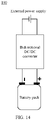
- FIG. 2 is a schematic diagram of a structure of a battery heating system 100 according to another embodiment of this application.
- the battery heating system 100 may include a temperature monitoring unit 110, a control unit 120, and a voltage conversion unit 130.
- the temperature monitoring unit 110 is configured to: monitor a temperature of the to-be-heated battery 30, and output a temperature monitoring signal, where the temperature monitoring signal is used to indicate the temperature of the to-be-heated battery 30.
- the temperature monitoring signal that is output by the temperature monitoring unit 110 may be a digital signal, or may be an analog signal.
- the temperature monitoring unit 110 may include a temperature sensor, and the temperature sensor may include a thermocouple, a negative temperature coefficient (negative temperature coefficient, NTC) temperature sensor, an infrared sensor, or the like.
- the temperature sensor may be disposed around the to-be-heated battery 30.
- the temperature monitoring signal may indicate a current temperature or a real-time temperature of the to-be-heated battery 30.
- the current temperature or the real-time temperature of the to-be-heated battery 30 may include an average temperature that is of the to-be-heated battery 30 and that is monitored in a latest time interval, or a temperature that is of the to-be-heated battery 30 and that is monitored before the latest time interval.
- a length of the latest time interval may be determined based on practice.
- the temperature monitoring unit may monitor the temperature of the to-be-heated battery 30, and output the temperature monitoring signal every 5 seconds (s). Alternatively, the temperature monitoring unit may continuously output the temperature monitoring signal in time domain.
- the temperature monitoring unit 110 may be implemented by a temperature sensor, or may be jointly implemented by an interface circuit of the control unit 120 and a temperature sensor.
- the interface circuit is connected to the temperature sensor, receives a sensing signal from the temperature sensor, and determines the temperature of the to-be-heated battery 30 based on the sensing signal.
- the control unit 120 is configured to: receive the temperature monitoring signal, and output a control signal to the voltage conversion unit 130 based on the temperature monitoring signal
- control unit 120 may determine a working mode of the battery heating system 100 based on the temperature indicated by the received temperature monitoring signal. For example, if the temperature of the to-be-heated battery 30 meets a normal working requirement, the control signal may indicate the voltage conversion unit 130 not to work. Alternatively, if the temperature of the to-be-heated battery 30 is lower than the normal working requirement, the control signal may indicate the voltage conversion unit 130 to work.
- the control unit 120 may indicate, by sending the control signal, the voltage conversion unit 130 to work; or indicate, by skipping sending the control signal, the voltage conversion unit 130 not to work.
- the voltage conversion unit 130 is separately connected to the power supply 20 and the to-be-heated battery 30, and receives a first voltage V 1 that is input by the power supply 20 or a second voltage V 2 that is input by the to-be-heated battery 30.
- the voltage conversion unit is configured to perform boosting or bucking processing on the first voltage V 1 based on the control signal or perform boosting or bucking processing on the second voltage V 2 based on the control signal, so that the to-be-heated battery receives a charging current from the power supply in a first time segment by using the voltage conversion unit, and the to-be-heated battery outputs a discharging current to the power supply in a second time segment by using the voltage conversion unit.
- the first voltage V 1 may be understood as a working voltage provided by the power supply 20, and the second voltage V 2 may be understood as a working voltage provided by the to-be-heated battery 30.
- the power supply 20 may include a direct-current power supply.
- the power supply 20 may include a battery, or the power supply 20 may be a direct-current power supply obtained after alternating-current/direct-current conversion is performed on an alternating-current power supply.
- a direct-current power supply may be obtained after alternating-current/direct-current conversion is performed on 50 Hz mains electricity.
- the voltage conversion unit 130 may include a first terminal A1, a second terminal A2, a third terminal A3, and a fourth terminal A4.
- the first terminal A1 and the second terminal A2 are respectively configured to connect to a positive electrode and a negative electrode of the power supply 20.
- the third terminal A3 and the fourth terminal A4 may be respectively configured to connect to a positive electrode and a negative electrode of the to-be-heated battery 30.
- the first terminal A1 and the second terminal A2 may be collectively referred to as a first end of the voltage conversion unit 130, and the third terminal A3 and the fourth terminal A4 may be collectively referred to as a second end of the voltage conversion unit 130.
- the voltage conversion unit 130 may be an apparatus in which a direct current can flow between the first end and the second end in dual directions.
- the voltage conversion unit 130 may perform boosting/bucking processing on the first voltage V 1 or the second voltage V 2 , so that charging and discharging are continuously performed between the to-be-heated battery 30 and the power supply 20, and the to-be-heated battery can heat itself based on Joule heat generated by the charging/discharging current. In other words, a battery is quickly and evenly heated by using Joule heat generated by an internal resistance of the battery.
- the voltage conversion unit 130 may control the to-be-heated battery 30 to be charged or discharge electricity based on a specific charging/discharging frequency.
- the first time segment may be a time interval used to charge the to-be-heated battery in a charging and discharging time period
- the second time segment may be a time interval used by the to-be-heated battery to discharge electricity in a charging and discharging time period.
- the power supply 20 is in a discharging state
- the to-be-heated battery 30 is in a charging state.
- the to-be-heated battery 30 is in a discharging state
- the power supply 20 is in a charging state.
- the power supply 20 charges the to-be-heated battery 30 in the first time segment by using the voltage conversion unit 130, and the to-be-heated battery 30 charges the power supply 20 in the second time segment by using the voltage conversion unit 130.
- the power supply 20 and the to-be-heated battery 30 may alternately charge each other and discharge electricity to each other until the to-be-heated battery is heated to a target temperature.
- the voltage conversion unit 130 further includes a control end, and the control end is configured to receive a control signal.
- the control signal is used to control the voltage conversion unit to perform boosting/bucking processing on an input voltage that is input by an input end, and output a boosted/bucked voltage by using another input end.
- alternating-current charging/discharging is performed on the to-be-heated battery to directly heat the battery from the inside of the battery.
- a large current may be selected to perform heating, and an internal resistance of the battery is high in a low temperature condition, so that a heat generation amount is high, and the temperature of the battery can quickly rise.
- the inside of an electrochemical cell of the battery participates in heat generation, and heat can be evenly distributed inside the entire battery, so that heating is even, thereby mitigating a problem of uneven heating caused by single-side heating in a conventional heating method.
- the inside of the battery is heated, and only the electrochemical cell is heated without heating an external component. Therefore, energy utilization is high.
- the voltage conversion unit 130 may include a bidirectional direct current to direct current (direct current to direct current, DC/DC) converter.
- the bidirectional DC/DC may implement bidirectional flowing of a direct current, or may implement bidirectional energy transmission.
- FIG. 3 is a schematic diagram of a structure of a bidirectional DC/DC converter according to an embodiment of this application.
- the bidirectional DC/DC converter includes two ends.
- a first end U1 includes a first terminal A1 and a second terminal A2.
- a second end U2 may include a third terminal A3 and a fourth terminal A4.
- the first terminal A1 and the third terminal A3 are positive terminals, and the second terminal A2 and the fourth terminal A4 are negative terminals.
- An output current of the U1 end is represented by a first current I 1
- an output current of the U2 end is represented by a second current I 2 .
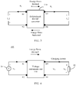
- FIG. 4 is a schematic diagram of a working status of a voltage conversion unit 130 according to an embodiment of this application.
- the voltage conversion unit 130 performs boosting or bucking processing on the first voltage V 1 that is output by the power supply 20, and outputs a third voltage V 3 , where the third voltage V 3 is used to be loaded at the two ends of the to-be-heated battery 30. If the third voltage V 3 is greater than the second voltage V 2 , the power supply 20 charges the to-be-heated battery 30 by using the voltage conversion unit 130; or if the third voltage V 3 is less than the second voltage V 2 , the to-be-heated battery 30 discharges electricity to the power supply 20 by using the voltage conversion unit 130.
- V 3 is greater than V 2 , and the power supply 20 charges the to-be-heated battery 20 by using the power conversion circuit 130.
- FIG. 5 is a schematic diagram of a working status of a voltage conversion unit 130 according to another embodiment of this application.
- the voltage conversion unit 130 may further perform boosting or bucking processing on the second voltage V 2 that is input by the to-be-heated battery 30, and outputs a fourth voltage V 4 , where the fourth voltage V 4 is used to be loaded at the two ends of the power supply 20. If the fourth voltage V 4 is greater than the first voltage V 1 , the to-be-heated battery 30 discharges electricity to the power supply by using the voltage conversion unit 130; or if the fourth voltage V 4 is less than the first voltage V 1 , the power supply 20 charges the to-be-heated battery 30 by using the voltage conversion unit 130.
- V 4 is greater than V 1 , and the to-be-heated battery 30 discharges electricity to the power supply by using the voltage conversion unit 130.
- the to-be-heated battery 30 may alternately implement a charging process and a discharging process by using the voltage conversion unit 130, so that the to-be-heated battery 30 is heated by using Joule heat generated by an internal resistance of the to-be-heated battery 30 in the charging/discharging process.
- This heating manner may be used to quickly and evenly heat a battery. This heating manner can mitigate a problem that heating is uneven when the outside of the battery is heated, heating efficiency is low, space is occupied, and a lifespan of the battery is greatly affected.
- the power supply 20 may also be charged or discharge electricity by using the voltage conversion unit 130. Therefore, when both the power supply 20 and the to-be-heated battery 30 are batteries, the power supply 20 may also perform Ohmic heating on the power supply 20 through charging and discharging.
- FIG. 6 is a schematic diagram of a charging/discharging current of a battery according to another embodiment of this application.
- an alternating-current pulse current of a specific frequency is applied to the battery to perform charging and discharging on the battery, so that the battery can be charged and discharge electricity in a short time period, and the battery is quickly and evenly heated by using Joule heat generated by an internal resistance of the battery.
- an alternating-current pulse is used, and a total amount of electricity injected into the battery or electricity flowing out of the battery in a heating process is approximately equal to zero. Therefore, working performance of the battery is not affected.
- Q represents power of the battery
- I represents a charging current or a discharging current
- R represents an internal resistance of the battery
- t represents charging duration or discharging duration
- control unit 120 is specifically configured to: output the control signal when the temperature monitoring signal indicates that the temperature of the to-be-heated battery 30 is lower than a preset threshold; and/or stop outputting the control signal when the temperature monitoring signal indicates that the temperature of the to-be-heated battery is higher than or equal to the preset threshold.
- the preset threshold may be determined based on a critical temperature at which the to-be-heated battery can work normally. When the temperature of the to-be-heated battery is lower than the critical temperature, performance of the to-be-heated battery deteriorates. For example, an available capacity of the to-be-heated battery greatly decreases or activity of the battery is reduced, or a lithium plating reaction occurs during charging.
- the preset threshold may be greater than or equal to the critical temperature.
- the preset threshold may be set to 0°C, 5°C, or 10°C, or may be set to any temperature ranging from 0°C to 15°C.
- the voltage conversion unit 130 performs charging/discharging processing on the to-be-heated battery based on the control signal.
- the control unit stops outputting the control signal the voltage conversion unit 130 does not receive the control signal. Therefore, the voltage conversion unit 130 is in an idle state, and does not perform charging/discharging processing on the to-be-heated battery 30, that is, the to-be-heated battery 30 does not need to be heated.
- control signal is used to control a charging/discharging frequency of the to-be-heated battery 30, so that the charging/discharging frequency of the to-be-heated battery 30 falls within a frequency range of a dynamic control area.
- the charging/discharging frequency of the to-be-heated battery 30 falls within the frequency range of the dynamic control area, only charge transfer occurs inside the to-be-heated battery 30, and there is no substance diffusion and transfer or a Faraday reaction does not occur. Therefore, when the charging/discharging frequency of the battery falls within the frequency range of the dynamic control area, a low-temperature lithium plating reaction hardly occurs.
- FIG. 7 shows an equivalent circuit model of a battery according to an embodiment of this application.
- the equivalent circuit model of the battery includes a battery internal resistance R ⁇ , a double-layer capacitance C d , a charge transfer resistance R ct , and a diffusion impedance Z w .
- An impedance Z of the battery may be represented by Formula (2).
- Z R ⁇ + 1 j ⁇ C d ⁇ R ct + Z w
- ⁇ represents an angular frequency of battery charging/discharging
- j represents an imaginary part of the impedance.
- the battery internal resistance R ⁇ represents an internal resistance of an electrolyte and an electrode inside the battery.
- the double-layer capacitance C d represents an equivalent capacitance formed by an active ion from the electrolyte. The active ion only changes charge distribution without generating a chemical reaction.
- the charge transfer resistance R ct and the diffusion impedance Z w may be collectively referred to as Faraday impedance, which is an equivalent impedance formed by an active ion from the electrolyte, and represents a resistance generated by a Faraday reaction.
- the Faraday reaction includes two processes: One process is charge transfer, and a generated resistance may be represented as Rct.
- the other process is substance diffusion and transfer, and an impedance generated by the process is represented by Z w .
- a value of the impedance Z w may be represented by Formula (3).
- Z w ⁇ ⁇ 1 / 2 1 ⁇ j
- ⁇ represents a factor related to substance transfer
- ⁇ represents the angular frequency of battery charging/discharging
- j represents the imaginary part of the impedance
- FIG. 8 is a schematic diagram of an electrochemical impedance spectroscopy of a battery according to an embodiment of this application.
- the electrochemical impedance spectroscopy may also be referred to as a Nyquist (Nyquist) plot.
- FIG. 8 shows impedances of the battery at different charging/discharging frequencies.
- a horizontal axis represents a real-part impedance of the battery, and a vertical axis represents an imaginary-part impedance of the battery.
- the electrochemical impedance spectroscopy is divided into three areas based on different impedance types of the battery: a dynamic control area, a hybrid control area, and a diffusion control area.
- a charging/discharging frequency of the battery is relatively high.
- the dynamic control area may include a high frequency area and an extremely high frequency area.
- a charging and discharging time period is relatively short, so that there is not enough time for substance transfer to occur inside the battery. Therefore, the diffusion impedance Z w caused by substance transfer disappears.
- the hybrid control area is a phase in which the battery transits from a non-Faraday reaction to a Faraday reaction.
- a frequency of the hybrid control area is lower than that of the dynamic control area.
- the charging/discharging frequency is relatively low, and both charge transfer and substance diffusion and transfer occur, that is, the Faraday reaction occurs in the charging/discharging process of the battery.
- a frequency of the diffusion control area is lower than that of the hybrid control area.
- a frequency range corresponding to the dynamic control area is not fixed and unchanged, but changes based on different current statuses of the battery.
- the frequency range of the dynamic control area may change based on a change of a working temperature.
- Table 1 shows a correspondence between a battery temperature and a battery impedance. As shown in Table 1, when the working temperature is -15°C, the frequency range of the dynamic control area may be a frequency area greater than 4 Hz.
- the control unit may control the charging/discharging frequency of the battery to fall within the frequency range of the dynamic control area, so that only charge transfer occurs inside the battery in the charging/discharging process, and there is no substance diffusion and transfer.
- a lithium plating reaction is prone to occur.
- the lithium plating reaction occurs in a substance diffusion and transfer process. Therefore, if substance diffusion and transfer does not occur inside the battery during charging and discharging, battery performance can be avoided from being affected by the lithium plating reaction occurring in the battery.
- a proper charging/discharging frequency may be selected in the frequency range of the dynamic control area to perform charging/discharging on the battery, so that the battery can be quickly and evenly heated on the premises that a low-temperature lithium plating reaction is avoided.
- the charging/discharging frequency can be set at a higher frequency to more effectively ensure charging performance of the battery.
- the voltage conversion unit 130 needs to be switched between a charging process and a discharging process by using a switch, and duration occupied by switch switching makes it difficult to more quickly switch between charging and discharging. Therefore, in practice, the charging/discharging frequency is usually set to be close to a lower limit of the frequency range of the dynamic control area to reduce difficulty of circuit implementation. For example, when the frequency range of the dynamic control area is 2 Hz, the charging/discharging frequency of the battery may be set to a value ranging from 2.5 Hz to 5 Hz.
- the control unit 120 may dynamically adjust the charging/discharging frequency of the battery, to optimize heating efficiency while ensuring security of battery performance.
- the control unit 120 may determine the charging/discharging frequency of the to-be-heated battery 30 in a plurality of manners, and then control the charging/discharging frequency of the to-be-heated battery 30 by using the control signal sent to the voltage conversion unit 130. Several methods for determining the charging/discharging frequency of the to-be-heated battery 30 are described below.
- the control unit 120 may determine, based on the temperature that is of the to-be-heated battery 30 and that is indicated by the temperature monitoring signal and a preset correspondence between a battery temperature and the frequency range of the dynamic control area, a first frequency range corresponding to the temperature of the to-be-heated battery 30.
- the control unit 120 is further configured to determine the charging/discharging frequency of the to-be-heated battery 30 based on the first frequency range.
- control unit 120 may determine a corresponding frequency range of the dynamic control area based on a monitored current temperature of the to-be-heated battery 30.
- the temperature monitoring signal indicates that the temperature of the to-be-heated battery 30 is -10°C
- a frequency range that is of the dynamic control area and that corresponds to the temperature is greater than 6 Hz, that is, the first frequency range is greater than 6 Hz. Therefore, the charging/discharging frequency of the to-be-heated battery 30 may be greater than 6 Hz, for example, 6.5 Hz.
- the preset correspondence between a battery temperature and the frequency range of the dynamic control area may be predetermined through a plurality of experiments. For example, a researcher may test an electrochemical impedance spectroscopy of a battery sample at different temperatures, and then perform electrochemical performance analysis based on the electrochemical impedance spectroscopy of the battery to determine frequency ranges of the dynamic control area that correspond to different temperatures, that is, determine the correspondence between a battery temperature and the frequency range of the dynamic control area.
- the correspondence may be stored in the control unit 120, or may be stored in a storage device that can be accessed by the control unit 120, so that the control unit 120 determines a corresponding frequency range of the dynamic control area based on a currently monitored battery temperature.
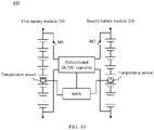
- FIG. 9 is a schematic diagram of a structure of a battery heating system 100 according to another embodiment of this application.
- the battery heating system 100 further includes an impedance monitoring unit 140.
- the impedance monitoring unit 140 is configured to: monitor an impedance of the to-be-heated battery 30, and output an impedance monitoring signal, where the impedance monitoring signal is used to indicate the impedance of the to-be-heated battery 30.
- the impedance monitoring unit 140 may be configured to monitor a current impedance of the to-be-heated battery 30 in real time.
- the impedance monitoring unit 140 may input an alternating current used for test to the to-be-heated battery 30, to detect an impedance of the battery in a current status.
- the control unit 120 may obtain an electrochemical impedance spectroscopy of the to-be-heated battery 30 in the current status based on the impedance monitoring signal sent by the impedance monitoring unit 140.
- the electrochemical impedance spectroscopy may be the electrochemical impedance spectroscopy shown in FIG. 8 .
- the electrochemical impedance spectroscopy is used to indicate a correspondence between the impedance and the charging/discharging frequency that are of the to-be-heated battery 30 in the current status.
- the control unit 120 may determine, based on the electrochemical impedance spectroscopy, a second frequency range that is of the dynamic control area and that corresponds to the to-be-heated battery 30 in the current status.
- the impedance monitoring unit 140 may detect impedances corresponding to alternating currents of different frequencies, to obtain impedances corresponding to the to-be-heated battery 30 at a plurality of frequencies, so as to obtain the electrochemical impedance spectroscopy of the to-be-heated battery 30.
- the control unit 120 may determine, by using the impedance monitoring signal that is of the to-be-heated battery 30 and that is monitored by the impedance monitoring unit 140 in real time, the frequency range that is of the dynamic control area and that corresponds to the to-be-heated battery 30 in the current status, and further determine the charging/discharging frequency of the to-be-heated battery 30.
- the current status includes a current temperature of the to-be-heated battery 30 and another real-time condition, for example, parameters such as dryness and humidity. Therefore, the frequency range of the dynamic control area is obtained through real-time detection based on the current status of the to-be-heated battery 30, and is not pre-obtained based on experimental data.
- the dynamic control area of the to-be-heated battery 30 can be determined more accurately, to improve accuracy of determining the charging/discharging frequency of the to-be-heated battery 30, and prevent a phenomenon such as a low-temperature lithium plating reaction from occurring due to improper setting of the charging/discharging frequency, affecting battery performance.
- the voltage conversion unit is further configured to perform boosting or bucking processing on the first voltage or perform boosting or bucking processing on the second voltage, so that a charging current received by the to-be-heated battery 30 in the first time segment is less than a maximum charging current.
- the charging current of the to-be-heated battery 30 should be less than a specific threshold.
- maximum charging currents allowed to pass through the battery are also different.
- a working condition of the battery may include factors such as a battery temperature, a state of charge (state of charge, SoC) of the battery, and a battery impedance.
- control unit 120 needs to dynamically determine a maximum charging current of the to-be-heated battery 30 based on a current working status of the to-be-heated battery 30, to control the charging current of the to-be-heated battery 30 to be less than the maximum charging current.
- control unit 120 may determine a maximum charging current of the to-be-heated battery 30 in a current status in a plurality of manners. Several manners used to determine the maximum charging current in this embodiment of this application are described below.
- control unit 120 may determine a current value of a current maximum charging current based on a state of charge and the temperature that is of the to-be-heated battery 30 and that is indicated by the temperature monitoring signal
- control unit 120 may pre-obtain a first correspondence between a battery temperature, a state of charge, and a current value of a maximum charging current, and then determine the current value of the current maximum charging current of the to-be-heated battery based on a current temperature and a current state of charge that are of the to-be-heated battery, and the first correspondence.
- control unit 120 may calculate and determine the state of charge of the to-be-heated battery 30 based on an electrical parameter of the to-be-heated battery 30 in the current status.
- the electrical parameter may include but is not limited to parameters such as an output voltage, an output current, and a temperature that are of the to-be-heated battery.
- the first correspondence between a battery temperature, a state of charge, and a current value of a maximum charging current may be predetermined through a plurality of experiments.
- the first correspondence may be stored in the control unit 120, or may be stored in a storage device that can be accessed by the control unit 120, so that the control unit 120 determines a corresponding current value of the maximum charging current based on a battery temperature and a state of charge that are currently monitored.
- the preset correspondence between a battery temperature and a current value of a maximum charging current may be provided by a battery manufacturer.
- Table 2 shows a correspondence between a battery temperature, a state of charge, and a current value of a maximum charging current.
- a battery with a capacity of 50 Ah (ampere hour, Ah) is used as an example for description.
- Table 2 shows maximum charging currents of the battery at different temperatures and in different states of charge (state of charge, SoC). For example, as shown in Table 2, when the working temperature is -10°C and the state of charge is 80%, the maximum charging current of the battery is 128 amps (ampere, A).
- I ch represents a maximum charging current of a battery
- V max represents a charging cut-off voltage of the battery
- V ocv represents an open circuit voltage of the battery at a specific SoC point
- R cn represents an internal resistance of the battery at a specified frequency.
- control unit 120 may recalculate, at intervals of a segment of time, the current value of the maximum charging current based on a feature that the internal resistance of the battery changes with a temperature, and adjust the charging current of the to-be-heated battery 30 based on the recalculated current value. For example, the control unit 120 may re-determine the current value of the maximum charging current each time the battery temperature rises by 2°C.
- the voltage conversion unit may be further configured to perform boosting or bucking processing on the first voltage V 1 or perform boosting or bucking processing on the second voltage V 2 , so that a discharging current that is output by the to-be-heated battery 30 in the second time segment is less than a maximum discharging current.
- the control unit 120 needs to determine a maximum discharging current of the to-be-heated battery 30 based on a current working status of the to-be-heated battery 30, to control the discharging current of the to-be-heated battery 30 to be less than the maximum discharging current.
- control unit 120 may determine a maximum discharging current of the to-be-heated battery 30 in a current status in a plurality of manners. Several manners used to determine the maximum discharging current in this embodiment of this application are described below.
- control unit 120 may be configured to determine a current value of a current maximum discharging current based on a state of charge and the temperature that is of the to-be-heated battery 30 and that is indicated by the temperature monitoring signal.
- control unit 120 may pre-obtain a second correspondence between a battery temperature, a state of charge, and a current value of a maximum discharging current, and then determine the current value of the current maximum charging current of the to-be-heated battery based on a current temperature and a current state of charge that are of the to-be-heated battery, and the second correspondence.
- the second correspondence between a battery temperature, a state of charge, and a current value of a maximum discharging current may be predetermined through an experiment.
- the second correspondence may be stored in the control unit 120, or may be stored in a storage device that can be accessed by the control unit 120, so that the control unit 120 determines a corresponding current value of the maximum discharging current based on a currently monitored battery temperature.
- the preset correspondence between a battery temperature and a current value of a maximum discharging current may be provided by a battery manufacturer.
- Table 3 shows a correspondence between a battery temperature and a current value of a maximum discharging current.
- a battery with a capacity of 50 Ah is used as an example for description.
- Table 3 shows maximum discharging currents of the battery at different temperatures and in different states of charge. For example, as shown in Table 3, when the working temperature is -10°C and the state of charge is 80%, the maximum discharging current of the battery is 530 A.
- I dis represents a maximum discharging current of a battery
- V min represents a discharging cut-off voltage of the battery
- V ocv represents an open circuit voltage of the battery at a specific SoC point
- R dis represents an internal resistance of the battery at a specified frequency.
- control unit 120 may recalculate, at intervals of a segment of time, the current value of the maximum discharging current based on a feature that the internal resistance of the battery changes with a temperature, and adjust the discharging current of the to-be-heated battery 30 based on the recalculated current value.
- control unit 120 may re-determine the current value of the maximum discharging current each time the battery temperature rises by 2°C.
- the voltage conversion unit may be further configured to perform boosting or bucking processing on the first voltage V 1 or perform boosting or bucking processing on the second voltage V 2 , so that a discharging current that is output by the to-be-heated battery 30 in the second time segment is less than a maximum discharging current.
- FIG. 10 is a schematic diagram of a battery heating system 100 according to another embodiment of this application.
- the solution in FIG. 10 may be applied to an in-vehicle system.
- the battery 20 and the to-be-heated battery 30 may be respectively a first battery module 210 and a second battery module 220 in FIG. 10 .
- the first battery module 210 and the second battery module 220 may heat each other through charging and discharging.
- the voltage conversion unit 130 may be a bidirectional DC/DC converter in FIG. 10 .
- the control unit 120 may be integrated into a BMS of the in-vehicle system.
- the temperature monitoring unit 110 may include a temperature sensor in FIG. 10 .
- a positive electrode and a negative electrode of the first battery module 210 are respectively configured to connect to a first input end A1 and a second input end A2 of the bidirectional DC/DC converter, and a positive electrode and a negative electrode of the second battery module 220 are respectively configured to connect to a third input end A3 and a fourth input end A4 of the bidirectional DC/DC converter.
- the BMS may be configured to connect to a control end of the bidirectional DC/DC converter, and output a control signal to the bidirectional DC/DC converter.
- a plurality of temperature sensors are separately disposed in the first battery module 210 and the second battery module 220 and are connected to the BMS, and output a temperature monitoring signal to the BMS.
- a switch line connected to the bidirectional DC/DC converter may be designed, so that the bidirectional DC/DC converter can be connected to another circuit by using the switch line.
- the bidirectional DC/DC converter may be multiplexed in another circuit, to reduce circuit costs and simplify design.
- a first switch circuit M1 may be disposed between the first battery module 210 and the bidirectional DC/DC converter.
- a second switch circuit M2 may be disposed between the second battery module 220 and the bidirectional DC/DC converter.
- the first switch transistor M1 and the second switch transistor M2 are in an off state.
- the first switch transistor M1 and the second switch transistor M2 are in an on state.
- an external heating component is not required, and only a circuit structure needs to be changed.
- a bidirectional DC/DC converter included in an energy storage module implements heating, so that a structure is simple and implementation costs are low.
- the BMS may control the bidirectional DC/DC converter to boost the first battery module 210, and the first battery module 210 charges the second battery module 220. In this case, the first battery module 210 discharges electricity, and the second battery module 220 is charged. In the latter half of a charging and discharging time period, the BMS may control the bidirectional DC/DC converter to boost the second battery module 220, and the first battery module 220 charges the first battery module 210. In this case, the first battery module 210 is charged, and the second battery module 220 discharges electricity.
- the foregoing charging and discharging processes are performed alternately until the first battery module 210 and the second battery module 220 reach a target temperature.
- the BMS may dynamically adjust a charging/discharging current and a charging/discharging frequency based on a change of a battery status, to optimize a heating effect.
- the battery heating system may adjust the bidirectional DC/DC to implement mutual charging/discharging between batteries or modules, and mutual transfer of a charge between two batteries/modules.
- a self-heating battery is implemented by using resistance heat in a charging/discharging process. Therefore, self-heating may be implemented between batteries/modules inside a same battery system without using an external power supply to perform heating, thereby simplifying a heating system.
- FIG. 11 is a schematic diagram of a battery heating system 100 according to another embodiment of this application. As shown in FIG. 11 , for a battery pack including 16 battery modules, the 16 battery modules may be divided into a first module set and a second module set. Each module set includes eight battery modules, and the first module set and the second module set are a power supply and a to-be-heated battery for each other. It should be noted that the control unit 120 and the temperature monitoring unit 110 of the battery heating system 100 are not shown in FIG. 11 to FIG. 15 .
- the control unit 120 in FIG. 11 to FIG. 15 may be implemented by a BMS in the in-vehicle system, or may be implemented by another processor in the in-vehicle system.
- the temperature monitoring unit 110 may be implemented by a temperature sensor disposed in a battery pack.
- FIG. 12 is a schematic diagram of a battery heating system 100 according to another embodiment of this application.
- the power supply 20 and the to-be-heated battery 30 may be different cells in a same battery module.
- the different cells may be connected by using bidirectional DC/DC, and self-heating of the batteries is implemented through charging and discharging. Therefore, the battery heating system may implement mutual charging and discharging between different cells inside a same module by adjusting the bidirectional DC/DC, to implement a self-heating battery, so that an external power supply does not need to be used to perform heating, and a heating system is simplified.
- FIG. 13 is a schematic diagram of a battery heating system 100 according to another embodiment of this application.
- the power supply 20 and the to-be-heated battery 30 may be separately a plurality of cells in a same battery module.
- a plurality of cells are connected in series and/or in parallel to form the power supply 20, and a plurality of cells are connected in series and/or in parallel to form the to-be-heated battery 30. Therefore, the battery heating system may implement mutual charging and discharging between different batteries inside a same module, to implement self-heating, so that an external power supply does not need to be used to perform heating, and a heating system is simplified.
- FIG. 14 is a schematic diagram of a battery heating system 100 according to another embodiment of this application.
- the power supply 20 may be an external power supply
- the to-be-heated battery 30 may be a battery pack.
- the external power supply means that the to-be-heated battery 30 and the power supply 20 belong to different battery systems.
- the external power supply may be a direct-current power supply, a battery, or the like.
- the external power supply is a battery pack in one in-vehicle system
- the power supply 20 is a battery pack in another in-vehicle system.
- FIG. 15 is a schematic diagram of a method 300 for controlling a battery heating system according to an embodiment of this application.
- the battery heating system includes: a temperature monitoring unit, configured to: monitor a temperature of a to-be-heated battery, and output a temperature monitoring signal, where the temperature monitoring signal is used to indicate the temperature of the to-be-heated battery; and a voltage conversion unit, separately connected to a power supply and the to-be-heated battery, and configured to receive a first voltage that is input by the power supply or a second voltage that is input by the to-be-heated battery.
- the method 300 includes:
- the outputting the control signal to the voltage conversion unit includes: outputting the control signal when the temperature monitoring signal indicates that the temperature of the to-be-heated battery is lower than a preset threshold.
- the method further includes: stopping outputting the control signal when the temperature monitoring signal indicates that the temperature of the to-be-heated battery is higher than or equal to the preset threshold.
- control signal is used to control a charging/discharging frequency of the to-be-heated battery, so that the charging/discharging frequency of the to-be-heated battery falls within a frequency range of a dynamic control area.
- the method further includes: determining, based on the temperature that is of the to-be-heated battery and that is indicated by the temperature monitoring signal and a preset correspondence between a battery temperature and the frequency range of the dynamic control area, a first frequency range that is of the dynamic control area and that corresponds to the temperature of the to-be-heated battery; and determining the charging/discharging frequency of the to-be-heated battery based on the first frequency range.
- the battery heating system further includes an impedance monitoring unit.
- the impedance monitoring unit is configured to: monitor an impedance of the to-be-heated battery, and output an impedance monitoring signal, where the impedance monitoring signal is used to indicate the impedance of the to-be-heated battery.
- the method further includes: obtaining the impedance monitoring signal; determining, based on the impedance monitoring signal, a second frequency range that is of the dynamic control area and that corresponds to the to-be-heated battery in a current status; and determining the charging/discharging frequency of the to-be-heated battery based on the second frequency range.
- control signal is used to control the voltage conversion unit to perform boosting or bucking processing on the first voltage or perform boosting or bucking processing on the second voltage, so that a charging current received by the to-be-heated battery in the first time segment is less than a maximum charging current.
- the method further includes: determining a current value of a current maximum charging current of the to-be-heated battery based on a state of charge and the temperature that is of the to-be-heated battery and that is indicated by the temperature monitoring signal.
- the battery heating system further includes an impedance monitoring unit.
- the impedance monitoring unit is configured to: monitor an impedance of the to-be-heated battery, and output an impedance monitoring signal, where the impedance monitoring signal is used to indicate the impedance of the to-be-heated battery.
- the method further includes: obtaining the impedance monitoring signal, and determining a current value of the maximum charging current based on the impedance monitoring signal.
- control signal is used to control the voltage conversion unit to perform boosting or bucking processing on the first voltage or perform boosting or bucking processing on the second voltage, so that a discharging current that is output by the to-be-heated battery in the second time segment is less than a maximum discharging current.
- the method further includes: determining a current value of a current maximum discharging current of the to-be-heated battery based on the temperature of the to-be-heated battery and a state of charge.
- the battery heating system further includes an impedance monitoring unit.
- the impedance monitoring unit is configured to: monitor an impedance of the to-be-heated battery, and output an impedance monitoring signal, where the impedance monitoring signal is used to indicate the impedance of the to-be-heated battery.
- the method further includes: obtaining the impedance monitoring signal, and determining a current value of the maximum discharging current based on the impedance monitoring signal
- the power supply includes a first battery module
- the to-be-heated battery includes a second battery module.
- FIG. 16 is a schematic diagram of a structure of a control device 400 according to an embodiment of this application.
- the control device 400 includes a processor 410 and a communications interface 420.
- the apparatus 400 may further include a memory 430.
- the memory 430 may be included in the processor 410.
- the processor 410, the communications interface 420, and the memory 430 communicate with each other by using an internal connection path.
- the memory 430 is configured to store instructions, and the processor 410 is configured to execute the instructions stored in the memory 430, to implement the control method provided in the embodiments of this application.
- control device 400 may be configured to perform functions of the control unit 120 in FIG. 2 and FIG. 9 , or perform functions of the BMS in FIG. 10 .
- the disclosed system, apparatus, and method may be implemented in other manners.
- the foregoing apparatus embodiments are merely examples.
- division of the units is merely logical function division and may be other division during actual implementation.
- a plurality of units or components may be combined or integrated into another system, or some features may be ignored or not performed.
- the displayed or discussed mutual couplings or direct couplings or communications connections may be implemented through some interfaces.
- the indirect couplings or communications connections between the apparatuses or units may be implemented in electronic, mechanical, or other forms.
- the units described as separate parts may or may not be physically separate, and parts displayed as units may or may not be physical units, and may be located in one position, or may be distributed on multiple network units. Some or all of the units may be selected depending on actual requirements to achieve the objectives of the solutions in the embodiments.
- the functions When the functions are implemented in a form of a software functional unit and sold or used as an independent product, the functions may be stored in a computer-readable storage medium. Based on such an understanding, the technical solutions of this application essentially, or the part contributing to the conventional technology, or some of the technical solutions may be implemented in a form of a software product.
- the computer software product is stored in a storage medium, and includes several instructions for instructing a computer device (which may be a personal computer, a server, or a network device) to perform all or some of the steps of the methods described in the embodiments of this application.
- the foregoing storage medium includes any medium that can store program code, such as a USB flash drive, a removable hard disk, a read-only memory (Read-Only Memory, ROM), a random access memory (Random Access Memory, RAM), a magnetic disk, or an optical disc.
- program code such as a USB flash drive, a removable hard disk, a read-only memory (Read-Only Memory, ROM), a random access memory (Random Access Memory, RAM), a magnetic disk, or an optical disc.
Abstract
Description
- This application claims priority to
Chinese Patent Application No. 201911089521.8, filed with the China National Intellectual Property Administration on November 8, 2019 - This application relates to the field of electronic technologies, and in particular, to a battery heating system, an electric vehicle, and an in-vehicle system.
- A typical battery pack is formed by connecting a plurality of cells in series or in parallel, and many types of battery packs include a rechargeable mono-cell battery. A mono-cell battery used to form a rechargeable battery pack needs to work in a proper temperature range. An excessively high or low battery temperature is not conducive to play battery performance, and is prone to cause a security risk. An available capacity of the battery greatly decreases at a relatively low temperature. As a result, the battery cannot discharge electricity or be charged in a low temperature condition. In addition, rate performance of the battery seriously deteriorates, which limits play of battery performance. In addition, in a low-temperature charging condition, a lithium plating reaction is prone to occur due to low battery activity. As a result, an internal short circuit of the battery occurs, causing a serious security risk. Therefore, in the low temperature condition, the battery needs to be heated to a proper temperature before use.
- In the conventional technology, an external heating manner such as heating using a wide-wire metal film or heating using an electric heating wire is usually used to control a temperature of a heater to rise, and then a battery is heated through contact conduction, cross ventilation, or heat transfer through liquid. This requires relatively large space and relatively high costs. In addition, a temperature gradient is prone to be formed in a battery pack through external heating, and most of energy is dissipated, and consequently energy utilization is low.
- This application provides a battery heating system, an electric vehicle, and an in-vehicle system, to quickly and evenly heat a battery.
- According to a first aspect, a battery heating system is provided, including: a temperature monitoring unit, configured to: monitor a temperature of a to-be-heated battery, and output a temperature monitoring signal, where the temperature monitoring signal is used to indicate the temperature of the to-be-heated battery; a voltage conversion unit, separately connected to a power supply and the to-be-heated battery, and configured to receive a first voltage that is input by the power supply or a second voltage that is input by the to-be-heated battery; and a control unit, configured to: receive the temperature monitoring signal, and output a control signal to the voltage conversion unit based on the temperature monitoring signal. The voltage conversion unit is configured to perform boosting or bucking processing on the first voltage based on the control signal or perform boosting or bucking processing on the second voltage based on the control signal, so that the to-be-heated battery receives a charging current from the power supply in a first time segment by using the voltage conversion unit, and the to-be-heated battery outputs a discharging current to the power supply in a second time segment by using the voltage conversion unit.
- Optionally, the battery heating system may be applied to an in-vehicle system, a mobile terminal, an outdoor energy storage system, or the like. The power supply and the to-be-heated battery may be different batteries in a same power supply system.
- Optionally, the battery heating system may be applied to an in-vehicle system in fields such as a pure electric vehicle/battery electric vehicle (pure electric vehicle/battery electric vehicle, pure EV/battery EV), a hybrid electric vehicle (hybrid electric vehicle, HEV), a range extended electric vehicle (range extended electric vehicle, REEV), a plug-in hybrid electric vehicle (plug-in hybrid electric vehicle, PHEV), and a new energy vehicle (new energy vehicle, NEV).
- For example, the power supply and the to-be-heated battery may be different battery modules in a same battery pack in an in-vehicle system.
- For example, the power supply and the to-be-heated battery may be different battery packs in an in-vehicle system. The first battery may include one or more battery modules, and the second battery may include one or more battery modules.
- For example, the power supply and the to-be-heated battery may be different battery packs in different in-vehicle systems.
- For example, the power supply and the to-be-heated battery may be different batteries or battery modules in a same mobile terminal; or the power supply and the to-be-heated battery may be batteries or battery modules in different mobile terminals.
- For example, the power supply and the to-be-heated battery may be separately different batteries in an outdoor energy storage system.
- In this embodiment of this application, the to-be-heated battery may alternately implement a charging process and a discharging process by using the voltage conversion unit, so that the to-be-heated battery is heated by using Joule heat generated by an internal resistance of the to-be-heated battery in the charging/discharging process. This heating manner may be used to quickly and evenly heat a battery. This heating manner can mitigate a problem that heating is uneven when the outside of the battery is heated, heating efficiency is low, space is occupied, and a lifespan of the battery is greatly affected.
- With reference to the first aspect, in a possible implementation of the first aspect, the control unit is specifically configured to output the control signal when the temperature monitoring signal indicates that the temperature of the to-be-heated battery is lower than a preset threshold. The control unit is further configured to stop outputting the control signal when the temperature monitoring signal indicates that the temperature of the to-be-heated battery is higher than or equal to the preset threshold.
- Optionally, the control unit is specifically configured to: when the temperature monitoring signal indicates that the temperature of the to-be-heated battery is lower than the preset threshold, output the control signal indicating to perform heating.
- Optionally, the control unit is further configured to: when the temperature monitoring signal indicates that the temperature of the to-be-heated battery is higher than or equal to the preset threshold, output the control signal indicating to stop performing heating. The voltage conversion unit is configured to stop, based on the control signal, performing boosting or bucking processing on the first voltage, and/or stop, based on the control signal, performing boosting or bucking processing on the second voltage.
- With reference to the first aspect, in a possible implementation of the first aspect, the control signal is used to control a charging/discharging frequency of the to-be-heated battery, so that the charging/discharging frequency of the to-be-heated battery falls within a frequency range of a dynamic control area.
- With reference to the first aspect, in a possible implementation of the first aspect, the control unit is configured to determine, based on the temperature that is of the to-be-heated battery and that is indicated by the temperature monitoring signal and a preset correspondence between a battery temperature and the frequency range of the dynamic control area, a first frequency range that is of the dynamic control area and that corresponds to the temperature of the to-be-heated battery. The control unit is further configured to determine the charging/discharging frequency of the to-be-heated battery based on the first frequency range.
- With reference to the first aspect, in a possible implementation of the first aspect, the system further includes an impedance monitoring unit. The impedance monitoring unit is configured to: monitor an impedance of the to-be-heated battery, and output an impedance monitoring signal, where the impedance monitoring signal is used to indicate the impedance of the to-be-heated battery. The control unit is configured to: receive the impedance monitoring signal, and determine, based on the impedance monitoring signal, a second frequency range that is of the dynamic control area and that corresponds to the to-be-heated battery in a current status. The control unit is further configured to determine the charging/discharging frequency of the to-be-heated battery based on the second frequency range.
- With reference to the first aspect, in a possible implementation of the first aspect, the voltage conversion unit is configured to perform boosting or bucking processing on the first voltage or perform boosting or bucking processing on the second voltage, so that a charging current received by the to-be-heated battery in the first time segment is less than a maximum charging current.
- With reference to the first aspect, in a possible implementation of the first aspect, the control unit is further configured to determine a current value of a current maximum charging current of the to-be-heated battery based on a state of charge and the temperature that is of the to-be-heated battery and that is indicated by the temperature monitoring signal.
- With reference to the first aspect, in a possible implementation of the first aspect, the system further includes an impedance monitoring unit. The impedance monitoring unit is configured to: monitor an impedance of the to-be-heated battery, and output an impedance monitoring signal, where the impedance monitoring signal is used to indicate the impedance of the to-be-heated battery. The control unit is configured to: receive the impedance monitoring signal, and determine a current value of the maximum charging current based on the impedance monitoring signal.
- With reference to the first aspect, in a possible implementation of the first aspect, the voltage conversion unit is configured to perform boosting or bucking processing on the first voltage or perform boosting or bucking processing on the second voltage, so that a discharging current that is output by the to-be-heated battery in the second time segment is less than a maximum discharging current.
- With reference to the first aspect, in a possible implementation of the first aspect, the control unit is further configured to determine a current value of a current maximum discharging current of the to-be-heated battery based on the temperature of the to-be-heated battery and a state of charge.
- With reference to the first aspect, in a possible implementation of the first aspect, the system further includes an impedance monitoring unit. The impedance monitoring unit is configured to: monitor an impedance of the to-be-heated battery, and output an impedance monitoring signal, where the impedance monitoring signal is used to indicate the impedance of the to-be-heated battery. The control unit is configured to: receive the impedance monitoring signal, and determine a current value of the maximum discharging current based on the impedance monitoring signal.
- With reference to the first aspect, in a possible implementation of the first aspect, the power supply includes a first battery module, and the to-be-heated battery includes a second battery module.
- According to a second aspect, a method for controlling a battery heating system is provided. The battery heating system includes: a temperature monitoring unit, configured to: monitor a temperature of a to-be-heated battery, and output a temperature monitoring signal, where the temperature monitoring signal is used to indicate the temperature of the to-be-heated battery; and a voltage conversion unit, separately connected to a power supply and the to-be-heated battery, and configured to receive a first voltage that is input by the power supply or a second voltage that is input by the to-be-heated battery. The method includes: obtaining the temperature monitoring signal, determining a control signal based on the temperature monitoring signal, and outputting the control signal to the voltage conversion unit, where the control signal is used to control the voltage conversion unit to perform boosting or bucking processing on the first voltage or perform boosting or bucking processing on the second voltage, so that the to-be-heated battery receives a charging current from the power supply in a first time segment by using the voltage conversion unit, and the to-be-heated battery outputs a discharging current to the power supply in a second time segment by using the voltage conversion unit.
- In this embodiment of this application, the to-be-heated battery may alternately implement a charging process and a discharging process by using the voltage conversion unit, so that the to-be-heated battery is heated by using Joule heat generated by an internal resistance of the to-be-heated battery in the charging/discharging process. This heating manner may be used to quickly and evenly heat a battery. This heating manner can mitigate a problem that heating is uneven when the outside of the battery is heated, heating efficiency is low, space is occupied, and a lifespan of the battery is greatly affected.
- With reference to the second aspect, in a possible implementation of the second aspect, the outputting the control signal to the voltage conversion unit includes: outputting the control signal when the temperature monitoring signal indicates that the temperature of the to-be-heated battery is lower than a preset threshold. The method further includes: stopping outputting the control signal when the temperature monitoring signal indicates that the temperature of the to-be-heated battery is higher than or equal to the preset threshold.
- Optionally, the outputting the control signal to the voltage conversion unit includes: when the temperature monitoring signal indicates that the temperature of the to-be-heated battery is lower than the preset threshold, outputting the control signal indicating to perform heating.
- Optionally, the method further includes: when the temperature monitoring signal indicates that the temperature of the to-be-heated battery is higher than or equal to the preset threshold, outputting the control signal indicating to stop performing heating. The voltage conversion unit is configured to stop, based on the control signal, performing boosting or bucking processing on the first voltage, and/or stop, based on the control signal, performing boosting or bucking processing on the second voltage.
- With reference to the second aspect, in a possible implementation of the second aspect, the control signal is used to control a charging/discharging frequency of the to-be-heated battery, so that the charging/discharging frequency of the to-be-heated battery falls within a frequency range of a dynamic control area.
- With reference to the second aspect, in a possible implementation of the second aspect, the method further includes: determining, based on the temperature that is of the to-be-heated battery and that is indicated by the temperature monitoring signal and a preset correspondence between a battery temperature and the frequency range of the dynamic control area, a first frequency range that is of the dynamic control area and that corresponds to the temperature of the to-be-heated battery; and determining the charging/discharging frequency of the to-be-heated battery based on the first frequency range.
- With reference to the second aspect, in a possible implementation of the second aspect, the battery heating system further includes an impedance monitoring unit. The impedance monitoring unit is configured to: monitor an impedance of the to-be-heated battery, and output an impedance monitoring signal, where the impedance monitoring signal is used to indicate the impedance of the to-be-heated battery. The method further includes: obtaining the impedance monitoring signal; determining, based on the impedance monitoring signal, a second frequency range that is of the dynamic control area and that corresponds to the to-be-heated battery in a current status; and determining the charging/discharging frequency of the to-be-heated battery based on the second frequency range.
- With reference to the second aspect, in a possible implementation of the second aspect, the control signal is used to control the voltage conversion unit to perform boosting or bucking processing on the first voltage or perform boosting or bucking processing on the second voltage, so that a charging current received by the to-be-heated battery in the first time segment is less than a maximum charging current.
- With reference to the second aspect, in a possible implementation of the second aspect, the method further includes: determining a current value of a current maximum charging current of the to-be-heated battery based on a state of charge and the temperature that is of the to-be-heated battery and that is indicated by the temperature monitoring signal.
- With reference to the second aspect, in a possible implementation of the second aspect, the battery heating system further includes an impedance monitoring unit. The impedance monitoring unit is configured to: monitor an impedance of the to-be-heated battery, and output an impedance monitoring signal, where the impedance monitoring signal is used to indicate the impedance of the to-be-heated battery. The method further includes: obtaining the impedance monitoring signal, and determining a current value of the maximum charging current based on the impedance monitoring signal.
- With reference to the second aspect, in a possible implementation of the second aspect, the control signal is used to control the voltage conversion unit to perform boosting or bucking processing on the first voltage or perform boosting or bucking processing on the second voltage, so that a discharging current that is output by the to-be-heated battery in the second time segment is less than a maximum discharging current.
- With reference to the second aspect, in a possible implementation of the second aspect, the method further includes: determining a current value of a current maximum discharging current of the to-be-heated battery based on the temperature of the to-be-heated battery and a state of charge.
- With reference to the second aspect, in a possible implementation of the second aspect, the battery heating system further includes an impedance monitoring unit. The impedance monitoring unit is configured to: monitor an impedance of the to-be-heated battery, and output an impedance monitoring signal, where the impedance monitoring signal is used to indicate the impedance of the to-be-heated battery. The method further includes: obtaining the impedance monitoring signal, and determining a current value of the maximum discharging current based on the impedance monitoring signal.
- With reference to the second aspect, in a possible implementation of the second aspect, the power supply includes a first battery module, and the to-be-heated battery includes a second battery module.
- According to a third aspect, a power supply system is provided, and the power supply system includes the battery heating system according to the first aspect or any one of the possible implementations of the first aspect; and the power supply and the to-be-heated battery.
- Optionally, the power supply system may include an in-vehicle system, a mobile terminal, an outdoor energy storage system, or the like. The power supply and the to-be-heated battery may be different batteries in a same power supply system. The first battery may include one or more battery modules, and the second battery may include one or more battery modules.
- For example, the power supply and the to-be-heated battery may be different battery modules in a same battery pack in an in-vehicle system.
- For example, the power supply and the to-be-heated battery may be different battery packs in an in-vehicle system.
- For example, the power supply and the to-be-heated battery may be different battery packs in different in-vehicle systems.
- For example, the power supply and the to-be-heated battery may be different battery modules in a same mobile terminal; or the power supply and the to-be-heated battery may be batteries or battery modules in different mobile terminals.
- For example, the power supply and the to-be-heated battery may be separately different batteries in an outdoor energy storage system.
- With reference to the third aspect, in a possible implementation of the third aspect, the power supply includes a first battery module, and the to-be-heated battery includes a second battery module.
- According to a fourth aspect, an in-vehicle system is provided, and the in-vehicle system includes the battery heating system according to the first aspect or any one of the possible implementations of the first aspect; and the power supply and the to-be-heated battery.
- With reference to the fourth aspect, in a possible implementation of the fourth aspect, the power supply includes a first battery module in a battery pack in the in-vehicle system, and the to-be-heated battery includes a second battery module in the battery pack.
- According to a fifth aspect, a control device is provided, including a processor, where the processor is configured to perform the method according to the second aspect or any one of the possible implementations of the second aspect. Further, the control device includes a memory. The memory is coupled to the processor, and the memory is configured to store a computer program. The processor is configured to execute the computer program, so that the control device performs the method according to the second aspect or any one of the possible implementations of the second aspect.
- According to a sixth aspect, a computer-readable medium is provided, including a computer program. When the computer program is executed on a computer, the computer is enabled to perform the method according to the second aspect or any one of the possible implementations of the second aspect.
- According to a seventh aspect, a control device is provided. The control device includes a unit configured to perform the method according to the second aspect or any one of the possible implementations of the second aspect. A function of the unit may be implemented by hardware, or may be implemented by executing corresponding software by hardware. It should be understood that, the term "unit" herein may refer to an application-specific integrated circuit (application-specific integrated circuit, ASIC), an electronic circuit, a processor (for example, a shared processor, a dedicated processor, or a group processor) configured to execute one or more software or firmware programs, a memory, a merged logic circuit, and/or another appropriate component that supports the described function.
- In the embodiments of this application, the control unit may be a chip or a chip system, such as a system on chip (system on chip, SoC).
- According to an eighth aspect, a chip is provided, and a processing circuit is disposed on the chip. The processor circuit is configured to perform the method according to the second aspect or any one of the possible implementations of the second aspect.
- According to a ninth aspect, an electric vehicle is provided, including: a first battery and a second battery; a voltage conversion unit, separately connected to the first battery and the second battery, and configured to receive a first voltage that is input by the first battery or a second voltage that is input by the second battery; a temperature monitoring unit, configured to: monitor a temperature of the second battery, and output a temperature monitoring signal, where the temperature monitoring signal is used to indicate the temperature of the second battery; and a control unit, configured to: receive the temperature monitoring signal, and output a control signal to the voltage conversion unit based on the temperature monitoring signal. The voltage conversion unit is configured to perform boosting or bucking processing on the first voltage based on the control signal or perform boosting or bucking processing on the second voltage based on the control signal, so that the second battery receives a charging current from the first battery in a first time segment by using the voltage conversion unit, and the second battery outputs a discharging current to the first battery in a second time segment by using the voltage conversion unit.
- Optionally, the electric vehicle may include a pure electric vehicle/battery electric vehicle (pure electric vehicle/battery electric vehicle, pure EV/battery EV), a hybrid electric vehicle (hybrid electric vehicle, HEV), a range extended electric vehicle (range extended electric vehicle, REEV), a plug-in hybrid electric vehicle (plug-in hybrid electric vehicle, PHEV), a new energy vehicle (new energy vehicle, NEV), and the like.
- For example, the first battery and the second battery may be different battery modules in a same battery pack in the electric vehicle. The first battery may include one or more battery modules, and the second battery may include one or more battery modules.
- For example, the first battery and the second battery may be different battery packs in the electric vehicle.
- Alternatively, the first battery and the second battery may be different battery packs in different electric vehicles. For example, the second battery may be a battery pack in the electric vehicle in the first aspect, and the first battery may be a battery pack in another electric vehicle.
- Alternatively, the first battery may be an external power supply, such as an external direct-current power supply, and the second battery may be a battery pack in the electric vehicle.
- In this embodiment of this application, the first battery and the second battery may alternately implement a charging process and a discharging process by using the voltage conversion unit, so that the first battery and the second battery are heated by using Joule heat generated by internal resistances of the first battery and the second battery in the charging/discharging process. This heating manner may be used to quickly and evenly heat a battery. This heating manner can mitigate a problem that heating is uneven when the outside of the battery is heated, heating efficiency is low, space is occupied, and a lifespan of the battery is greatly affected.
- With reference to the ninth aspect, in some possible implementations of the ninth aspect, the control unit is specifically configured to output the control signal when the temperature monitoring signal indicates that the temperature of the second battery is lower than a preset threshold. The control unit is further configured to stop outputting the control signal when the temperature monitoring signal indicates that the temperature of the second battery is higher than or equal to the preset threshold.
- With reference to the ninth aspect, in some possible implementations of the ninth aspect, the control signal is used to control a charging/discharging frequency of the second battery, so that the charging/discharging frequency of the second battery falls within a frequency range of a dynamic control area.
- With reference to the ninth aspect, in some possible implementations of the ninth aspect, the control unit is configured to determine, based on the temperature that is of the second battery and that is indicated by the temperature monitoring signal and a preset correspondence between a battery temperature and the frequency range of the dynamic control area, a first frequency range that is of the dynamic control area and that corresponds to the temperature of the second battery. The control unit is further configured to determine the charging/discharging frequency of the second battery based on the first frequency range.
- With reference to the ninth aspect, in some possible implementations of the ninth aspect, the vehicle further includes an impedance monitoring unit. The impedance monitoring unit is configured to: monitor an impedance of the second battery, and output an impedance monitoring signal, where the impedance monitoring signal is used to indicate the impedance of the second battery. The control unit is configured to: receive the impedance monitoring signal, and determine, based on the impedance monitoring signal, a second frequency range that is of the dynamic control area and that corresponds to the second battery in a current status. The control unit is further configured to determine the charging/discharging frequency of the second battery based on the second frequency range.
- With reference to the ninth aspect, in some possible implementations of the ninth aspect, the voltage conversion unit is configured to perform boosting or bucking processing on the first voltage or perform boosting or bucking processing on the second voltage, so that a charging current received by the second battery in the first time segment is less than a maximum charging current.
- With reference to the ninth aspect, in some possible implementations of the ninth aspect, the voltage conversion unit is configured to perform boosting or bucking processing on the first voltage or perform boosting or bucking processing on the second voltage, so that a discharging current that is output by the second battery in the second time segment is less than a maximum discharging current.
- With reference to the ninth aspect, in some possible implementations of the ninth aspect, the vehicle further includes a battery pack, the first battery includes at least one first battery module in the battery pack, and the second battery includes at least one second battery module in the battery pack.
-
-
FIG. 1 is a schematic diagram of a structure of abattery heating system 100 according to an embodiment of this application; -
FIG. 2 is a schematic diagram of a structure of abattery heating system 100 according to another embodiment of this application; -
FIG. 3 is a schematic diagram of a structure of a bidirectional DC/DC converter according to an embodiment of this application; -
FIG. 4 is a schematic diagram of a working status of avoltage conversion unit 130 according to an embodiment of this application; -
FIG. 5 is a schematic diagram of a working status of avoltage conversion unit 130 according to another embodiment of this application; -
FIG. 6 is a schematic diagram of a charging/discharging current of a battery according to another embodiment of this application; -
FIG. 7 shows an equivalent circuit model of a battery according to an embodiment of this application; -
FIG. 8 is a schematic diagram of an electrochemical impedance spectroscopy of a battery according to an embodiment of this application; -
FIG. 9 is a schematic diagram of a structure of abattery heating system 100 according to another embodiment of this application; -
FIG. 10 is a schematic diagram of abattery heating system 100 according to another embodiment of this application; -
FIG. 11 is a schematic diagram of abattery heating system 100 according to another embodiment of this application; -
FIG. 12 is a schematic diagram of abattery heating system 100 according to another embodiment of this application; -
FIG. 13 is a schematic diagram of abattery heating system 100 according to another embodiment of this application; -
FIG. 14 is a schematic diagram of abattery heating system 100 according to another embodiment of this application; -
FIG. 15 is a schematic diagram of amethod 300 for controlling a battery heating system according to an embodiment of this application; and -
FIG. 16 is a schematic diagram of a structure of acontrol device 400 according to an embodiment of this application. - The following describes the technical solutions in this application with reference to the accompanying drawings.
- For ease of understanding, several terms or concepts related to the embodiments of this application are first described below.
- A lithium-ion battery (lithium-ion cell) is an apparatus that implements mutual conversion between chemical energy and electric energy by relying on movement of a lithium ion between a positive electrode and a negative electrode. The apparatus includes an electrode, a diaphragm, an electrolyte, a housing, a terminal, and the like, and is designed to be rechargeable. In the embodiments of this application, the lithium-electron battery may also be referred to as an electrochemical cell, a mono-cell battery, a mono-cell battery, or the like.
- A lithium-ion battery module (lithium-ion cell module) is a combination that combines more than one cell in a series, in parallel, or in series and parallel and that is used as a power supply. The lithium-ion battery module has only one pair of positive-electrode and negative-electrode output terminals, and may also be referred to as a lithium-ion battery module, a battery module, or the like in the embodiments of this application.
- A battery management system (battery management system, BMS) is a system for managing a battery, and usually includes a monitoring module and an operation control module. The BMS mainly includes two parts: a battery monitoring unit (battery monitor unit, BMU) and a battery control unit (battery control unit, BCU).
- A lithium-ion battery pack (lithium-ion pack) is a unit that can obtain electric energy from the outside and output electric energy to the outside, and usually includes at least one lithium-ion battery module, a lithium-ion battery management module (a BCU is not included), a lithium-ion battery box, and a corresponding accessory.
- A lithium-ion battery system (lithium-ion system) is an energy storage apparatus, and usually includes one or more lithium-ion battery packs and a corresponding accessory. The accessory may include a battery management system, a high voltage circuit, a low voltage circuit, a heat management device, a mechanical assembly, and the like.
- A Faraday reaction, also referred to as an electrochemical reaction, means that two processes simultaneously occur on an electrode, where one process is charge transfer and the other process is substance diffusion and transfer. Charge transfer may mean that a charge is transferred in a metal-solution interface, and substance diffusion and transfer may mean that electron transfer causes an oxidation or reduction reaction. These reactions are referred to as Faraday reactions because these reactions comply with the Faraday's law, that is, a quantity of chemical reactions caused by passing of a current is proportional to an amount of passed electricity.
- A lithium plating reaction means that in a process of charging a lithium-ion battery, a lithium ion is extracted from a positive electrode and inserted into a negative electrode. However, when some abnormal conditions occur, and the lithium ion extracted from the positive electrode cannot be inserted into the negative electrode, the lithium ion can be only plated on a surface of the negative electrode. This is referred to as the lithium plating reaction. For example, the lithium ion may generate the lithium plating reaction when being charged at a low temperature.
-
FIG. 1 is a schematic diagram of a structure of abattery heating system 100 according to an embodiment of this application. As shown inFIG. 1 , thesystem 100 is connected to apower supply 20 and a to-be-heated battery 30, and is configured to heat the to-be-heated battery 30 at a low temperature. It should be noted that the solutions in the embodiments of this application may be widely applied to an in-vehicle system, a mobile terminal, an outdoor energy storage system, and the like. Alternatively, thebattery heating system 100 in this embodiment of this application may be further applied to another field in which a battery needs to be heated. The outdoor energy storage system may include a standby power supply system of a base station and the like. - In some examples, the
power supply 20 and the to-be-heated battery 30 may be different batteries in a same power supply system, and the power supply system may be an in-vehicle system, a mobile terminal, or an outdoor energy storage system. - In some examples, the battery heating system may be applied to an in-vehicle system in fields such as a pure electric vehicle/battery electric vehicle (pure electric vehicle/battery electric vehicle, pure EV/battery EV), a hybrid electric vehicle (hybrid electric vehicle, HEV), a range extended electric vehicle (range extended electric vehicle, REEV), a plug-in hybrid electric vehicle (plug-in hybrid electric vehicle, PHEV), and a new energy vehicle (new energy vehicle, NEV).
- In some examples, the
power supply 20 and the to-be-heated battery 30 may be different battery modules in a same battery pack in an in-vehicle system. Charging and discharging may be performed between the different battery modules by using thebattery heating system 100, and the batteries are simultaneously heated. The battery module may include the foregoing lithium-ion battery module, and the battery pack may include the foregoing lithium-ion battery pack. The in-vehicle system may include the foregoing lithium-ion battery system. - In some examples, the
power supply 20 and the to-be-heated battery 30 may be different battery packs in an in-vehicle system, for example, the different battery packs may correspond to a high-voltage power supply system and a low-voltage power supply system in the in-vehicle system. - In some examples, the
power supply 20 and the to-be-heated battery 30 may be different battery packs in different in-vehicle systems. In other words, charging and discharging may be performed between different vehicles by using thebattery heating system 100. - In some examples, the
power supply 20 and the to-be-heated battery 30 may be different battery modules in a same mobile terminal; or thepower supply 20 and the to-be-heated battery 30 may be batteries or battery modules in different mobile terminals. - In some examples, the
power supply 20 and the to-be-heated battery 30 may be separately different batteries in an outdoor energy storage system. -
FIG. 2 is a schematic diagram of a structure of abattery heating system 100 according to another embodiment of this application. As shown inFIG. 2 , thebattery heating system 100 may include a temperature monitoring unit 110, acontrol unit 120, and avoltage conversion unit 130. - The temperature monitoring unit 110 is configured to: monitor a temperature of the to-
be-heated battery 30, and output a temperature monitoring signal, where the temperature monitoring signal is used to indicate the temperature of the to-be-heated battery 30. - For example, the temperature monitoring signal that is output by the temperature monitoring unit 110 may be a digital signal, or may be an analog signal. The temperature monitoring unit 110 may include a temperature sensor, and the temperature sensor may include a thermocouple, a negative temperature coefficient (negative temperature coefficient, NTC) temperature sensor, an infrared sensor, or the like. The temperature sensor may be disposed around the to-
be-heated battery 30. - Optionally, the temperature monitoring signal may indicate a current temperature or a real-time temperature of the to-
be-heated battery 30. It can be understood by a person skilled in the art that in some scenarios, depending on a specific manner of detecting a temperature by the temperature monitoring unit 110, the current temperature or the real-time temperature of the to-be-heated battery 30 may include an average temperature that is of the to-be-heated battery 30 and that is monitored in a latest time interval, or a temperature that is of the to-be-heated battery 30 and that is monitored before the latest time interval. A length of the latest time interval may be determined based on practice. For example, the temperature monitoring unit may monitor the temperature of the to-be-heated battery 30, and output the temperature monitoring signal every 5 seconds (s). Alternatively, the temperature monitoring unit may continuously output the temperature monitoring signal in time domain. - In some specific examples, the temperature monitoring unit 110 may be implemented by a temperature sensor, or may be jointly implemented by an interface circuit of the
control unit 120 and a temperature sensor. The interface circuit is connected to the temperature sensor, receives a sensing signal from the temperature sensor, and determines the temperature of the to-be-heated battery 30 based on the sensing signal. - The
control unit 120 is configured to: receive the temperature monitoring signal, and output a control signal to thevoltage conversion unit 130 based on the temperature monitoring signal - Optionally, the
control unit 120 may determine a working mode of thebattery heating system 100 based on the temperature indicated by the received temperature monitoring signal. For example, if the temperature of the to-be-heated battery 30 meets a normal working requirement, the control signal may indicate thevoltage conversion unit 130 not to work. Alternatively, if the temperature of the to-be-heated battery 30 is lower than the normal working requirement, the control signal may indicate thevoltage conversion unit 130 to work. Optionally, thecontrol unit 120 may indicate, by sending the control signal, thevoltage conversion unit 130 to work; or indicate, by skipping sending the control signal, thevoltage conversion unit 130 not to work. - The
voltage conversion unit 130 is separately connected to thepower supply 20 and the to-be-heated battery 30, and receives a first voltage V1 that is input by thepower supply 20 or a second voltage V2 that is input by the to-be-heated battery 30. The voltage conversion unit is configured to perform boosting or bucking processing on the first voltage V1 based on the control signal or perform boosting or bucking processing on the second voltage V2 based on the control signal, so that the to-be-heated battery receives a charging current from the power supply in a first time segment by using the voltage conversion unit, and the to-be-heated battery outputs a discharging current to the power supply in a second time segment by using the voltage conversion unit. - Optionally, the first voltage V1 may be understood as a working voltage provided by the
power supply 20, and the second voltage V2 may be understood as a working voltage provided by the to-be-heated battery 30. - Optionally, the
power supply 20 may include a direct-current power supply. For example, thepower supply 20 may include a battery, or thepower supply 20 may be a direct-current power supply obtained after alternating-current/direct-current conversion is performed on an alternating-current power supply. For example, a direct-current power supply may be obtained after alternating-current/direct-current conversion is performed on 50 Hz mains electricity. - As shown in
FIG. 2 , thevoltage conversion unit 130 may include a first terminal A1, a second terminal A2, a third terminal A3, and a fourth terminal A4. The first terminal A1 and the second terminal A2 are respectively configured to connect to a positive electrode and a negative electrode of thepower supply 20. The third terminal A3 and the fourth terminal A4 may be respectively configured to connect to a positive electrode and a negative electrode of the to-be-heated battery 30. The first terminal A1 and the second terminal A2 may be collectively referred to as a first end of thevoltage conversion unit 130, and the third terminal A3 and the fourth terminal A4 may be collectively referred to as a second end of thevoltage conversion unit 130. Thevoltage conversion unit 130 may be an apparatus in which a direct current can flow between the first end and the second end in dual directions. - The
voltage conversion unit 130 may perform boosting/bucking processing on the first voltage V1 or the second voltage V2, so that charging and discharging are continuously performed between the to-be-heated battery 30 and thepower supply 20, and the to-be-heated battery can heat itself based on Joule heat generated by the charging/discharging current. In other words, a battery is quickly and evenly heated by using Joule heat generated by an internal resistance of the battery. - In some examples, the
voltage conversion unit 130 may control the to-be-heated battery 30 to be charged or discharge electricity based on a specific charging/discharging frequency. The first time segment may be a time interval used to charge the to-be-heated battery in a charging and discharging time period, and the second time segment may be a time interval used by the to-be-heated battery to discharge electricity in a charging and discharging time period. In the first time segment, thepower supply 20 is in a discharging state, and the to-be-heated battery 30 is in a charging state. In the second time segment, the to-be-heated battery 30 is in a discharging state, and thepower supply 20 is in a charging state. Alternatively, thepower supply 20 charges the to-be-heated battery 30 in the first time segment by using thevoltage conversion unit 130, and the to-be-heated battery 30 charges thepower supply 20 in the second time segment by using thevoltage conversion unit 130. Thepower supply 20 and the to-be-heated battery 30 may alternately charge each other and discharge electricity to each other until the to-be-heated battery is heated to a target temperature. - Optionally, the
voltage conversion unit 130 further includes a control end, and the control end is configured to receive a control signal. The control signal is used to control the voltage conversion unit to perform boosting/bucking processing on an input voltage that is input by an input end, and output a boosted/bucked voltage by using another input end. - In this embodiment of this application, alternating-current charging/discharging is performed on the to-be-heated battery to directly heat the battery from the inside of the battery. In this method, a large current may be selected to perform heating, and an internal resistance of the battery is high in a low temperature condition, so that a heat generation amount is high, and the temperature of the battery can quickly rise.
- In addition, in the solution in this embodiment of this application, the inside of an electrochemical cell of the battery participates in heat generation, and heat can be evenly distributed inside the entire battery, so that heating is even, thereby mitigating a problem of uneven heating caused by single-side heating in a conventional heating method.
- In addition, in the solution in this embodiment of this application, the inside of the battery is heated, and only the electrochemical cell is heated without heating an external component. Therefore, energy utilization is high.
- Optionally, the
voltage conversion unit 130 may include a bidirectional direct current to direct current (direct current to direct current, DC/DC) converter. The bidirectional DC/DC may implement bidirectional flowing of a direct current, or may implement bidirectional energy transmission. For example,FIG. 3 is a schematic diagram of a structure of a bidirectional DC/DC converter according to an embodiment of this application. As shown inFIG. 3 , the bidirectional DC/DC converter includes two ends. A first end U1 includes a first terminal A1 and a second terminal A2. A second end U2 may include a third terminal A3 and a fourth terminal A4. The first terminal A1 and the third terminal A3 are positive terminals, and the second terminal A2 and the fourth terminal A4 are negative terminals. An output current of the U1 end is represented by a first current I1, and an output current of the U2 end is represented by a second current I2. When energy is transmitted from the U1 end to the U2 end, the energy is transmitted forward, and a current direction is that I1<0 and I2>0. When the energy is transmitted from the U2 end to the U1 end, the energy is transmitted backward, and the current direction is that I1>0 and I2<0. -
FIG. 4 is a schematic diagram of a working status of avoltage conversion unit 130 according to an embodiment of this application. As shown inFIG. 4 , thevoltage conversion unit 130 performs boosting or bucking processing on the first voltage V1 that is output by thepower supply 20, and outputs a third voltage V3, where the third voltage V3 is used to be loaded at the two ends of the to-be-heated battery 30. If the third voltage V3 is greater than the second voltage V2, thepower supply 20 charges the to-be-heated battery 30 by using thevoltage conversion unit 130; or if the third voltage V3 is less than the second voltage V2, the to-be-heated battery 30 discharges electricity to thepower supply 20 by using thevoltage conversion unit 130. - For example, if V1=18 V, V2=18 V, and V3=19.5 V, V3 is greater than V2, and the
power supply 20 charges the to-be-heated battery 20 by using thepower conversion circuit 130. Alternatively, if V1=18 V, V2=18 V, and V3=16.5 V, V3 is less than V2, and the to-be-heated battery 30 discharges electricity to thepower supply 20 by using thevoltage conversion unit 130. -
FIG. 5 is a schematic diagram of a working status of avoltage conversion unit 130 according to another embodiment of this application. Thevoltage conversion unit 130 may further perform boosting or bucking processing on the second voltage V2 that is input by the to-be-heated battery 30, and outputs a fourth voltage V4, where the fourth voltage V4 is used to be loaded at the two ends of thepower supply 20. If the fourth voltage V4 is greater than the first voltage V1, the to-be-heated battery 30 discharges electricity to the power supply by using thevoltage conversion unit 130; or if the fourth voltage V4 is less than the first voltage V1, thepower supply 20 charges the to-be-heated battery 30 by using thevoltage conversion unit 130. - For example, if V1=18 V, V2=18 V, and V4=19.5 V, V4 is greater than V1, and the to-
be-heated battery 30 discharges electricity to the power supply by using thevoltage conversion unit 130. Alternatively, if V1=18 V, V2=18 V, and V4=16.5 V, V4 is less than V1, and thepower supply 20 charges the to-be-heated battery 30 by using thevoltage conversion unit 130. - In this embodiment of this application, the to-
be-heated battery 30 may alternately implement a charging process and a discharging process by using thevoltage conversion unit 130, so that the to-be-heated battery 30 is heated by using Joule heat generated by an internal resistance of the to-be-heated battery 30 in the charging/discharging process. This heating manner may be used to quickly and evenly heat a battery. This heating manner can mitigate a problem that heating is uneven when the outside of the battery is heated, heating efficiency is low, space is occupied, and a lifespan of the battery is greatly affected. - In addition, it should be noted that when the to-
be-heated battery 30 is charged or discharges electricity by using thevoltage conversion unit 130, thepower supply 20 may also be charged or discharge electricity by using thevoltage conversion unit 130. Therefore, when both thepower supply 20 and the to-be-heated battery 30 are batteries, thepower supply 20 may also perform Ohmic heating on thepower supply 20 through charging and discharging. -
FIG. 6 is a schematic diagram of a charging/discharging current of a battery according to another embodiment of this application. As shown inFIG. 6 , an alternating-current pulse current of a specific frequency is applied to the battery to perform charging and discharging on the battery, so that the battery can be charged and discharge electricity in a short time period, and the battery is quickly and evenly heated by using Joule heat generated by an internal resistance of the battery. In addition, an alternating-current pulse is used, and a total amount of electricity injected into the battery or electricity flowing out of the battery in a heating process is approximately equal to zero. Therefore, working performance of the battery is not affected. - Power for generating Joule heat when a current flows through the battery may be represented by the following formula (1).

- Q represents power of the battery, I represents a charging current or a discharging current, R represents an internal resistance of the battery, and t represents charging duration or discharging duration.
- Optionally, the
control unit 120 is specifically configured to: output the control signal when the temperature monitoring signal indicates that the temperature of the to-be-heated battery 30 is lower than a preset threshold; and/or stop outputting the control signal when the temperature monitoring signal indicates that the temperature of the to-be-heated battery is higher than or equal to the preset threshold. - The preset threshold may be determined based on a critical temperature at which the to-be-heated battery can work normally. When the temperature of the to-be-heated battery is lower than the critical temperature, performance of the to-be-heated battery deteriorates. For example, an available capacity of the to-be-heated battery greatly decreases or activity of the battery is reduced, or a lithium plating reaction occurs during charging. The preset threshold may be greater than or equal to the critical temperature. For example, the preset threshold may be set to 0°C, 5°C, or 10°C, or may be set to any temperature ranging from 0°C to 15°C.
- Optionally, when the
control unit 120 outputs the control signal, thevoltage conversion unit 130 performs charging/discharging processing on the to-be-heated battery based on the control signal. When the control unit stops outputting the control signal, thevoltage conversion unit 130 does not receive the control signal. Therefore, thevoltage conversion unit 130 is in an idle state, and does not perform charging/discharging processing on the to-be-heated battery 30, that is, the to-be-heated battery 30 does not need to be heated. - Optionally, the control signal is used to control a charging/discharging frequency of the to-
be-heated battery 30, so that the charging/discharging frequency of the to-be-heated battery 30 falls within a frequency range of a dynamic control area. When the charging/discharging frequency of the to-be-heated battery 30 falls within the frequency range of the dynamic control area, only charge transfer occurs inside the to-be-heated battery 30, and there is no substance diffusion and transfer or a Faraday reaction does not occur. Therefore, when the charging/discharging frequency of the battery falls within the frequency range of the dynamic control area, a low-temperature lithium plating reaction hardly occurs. - To help describe a concept of the dynamic control area, an electrochemical implementation principle of a battery in the embodiments of this application is described below with reference to the accompanying drawings.
-
FIG. 7 shows an equivalent circuit model of a battery according to an embodiment of this application. As shown inFIG. 7 , the equivalent circuit model of the battery includes a battery internal resistance RΩ, a double-layer capacitance Cd, a charge transfer resistance Rct, and a diffusion impedance Zw. An impedance Z of the battery may be represented by Formula (2).
- In the formula, ω represents an angular frequency of battery charging/discharging, and j represents an imaginary part of the impedance. The battery internal resistance RΩ represents an internal resistance of an electrolyte and an electrode inside the battery. The double-layer capacitance Cd represents an equivalent capacitance formed by an active ion from the electrolyte. The active ion only changes charge distribution without generating a chemical reaction. The charge transfer resistance Rct and the diffusion impedance Zw may be collectively referred to as Faraday impedance, which is an equivalent impedance formed by an active ion from the electrolyte, and represents a resistance generated by a Faraday reaction. The Faraday reaction includes two processes: One process is charge transfer, and a generated resistance may be represented as Rct. The other process is substance diffusion and transfer, and an impedance generated by the process is represented by Zw. A value of the impedance Zw may be represented by Formula (3).

- In the formula, σ represents a factor related to substance transfer, ω represents the angular frequency of battery charging/discharging, and j represents the imaginary part of the impedance.
-
FIG. 8 is a schematic diagram of an electrochemical impedance spectroscopy of a battery according to an embodiment of this application. The electrochemical impedance spectroscopy may also be referred to as a Nyquist (Nyquist) plot.FIG. 8 shows impedances of the battery at different charging/discharging frequencies. A horizontal axis represents a real-part impedance of the battery, and a vertical axis represents an imaginary-part impedance of the battery. As shown inFIG. 8 , the electrochemical impedance spectroscopy is divided into three areas based on different impedance types of the battery: a dynamic control area, a hybrid control area, and a diffusion control area. - In the dynamic control area, a charging/discharging frequency of the battery is relatively high. In a charging/discharging process of the battery, only charge transfer occurs, and there is no substance diffusion and transfer. In other words, the Faraday reaction does not occur in the battery in the dynamic control area. The dynamic control area may include a high frequency area and an extremely high frequency area. In the high frequency area, a charging and discharging time period is relatively short, so that there is not enough time for substance transfer to occur inside the battery. Therefore, the diffusion impedance Zw caused by substance transfer disappears. In the extremely high frequency area, the double-layer capacitance Cd makes the charge transfer resistance Rct and the diffusion impedance Zw short-circuited, and the battery presents a pure resistance feature. Therefore, the battery impedance may be represented as Z=RΩ.
- The hybrid control area is a phase in which the battery transits from a non-Faraday reaction to a Faraday reaction. A frequency of the hybrid control area is lower than that of the dynamic control area.
- In the diffusion control area, the charging/discharging frequency is relatively low, and both charge transfer and substance diffusion and transfer occur, that is, the Faraday reaction occurs in the charging/discharging process of the battery. A frequency of the diffusion control area is lower than that of the hybrid control area.
- It should be noted that a frequency range corresponding to the dynamic control area is not fixed and unchanged, but changes based on different current statuses of the battery. For example, the frequency range of the dynamic control area may change based on a change of a working temperature. For example, Table 1 shows a correspondence between a battery temperature and a battery impedance. As shown in Table 1, when the working temperature is -15°C, the frequency range of the dynamic control area may be a frequency area greater than 4 Hz.
Table 1 Temperature (°C) Dynamic control area (Hz) Hybrid control area (Hz) Diffusion control area (Hz) -30 >1 0.02-1 <0.02 -25 >2 0.04-2 <0.04 -20 >3 0.07-3 <0.07 -15 >4 0.11-4 <0.11 -10 >6 0.15-6 <0.15 -5 >8 0.21-8 <0.21 0 >10 0.25-10 <0.25 5 >12 0.34-12 <0.34 10 >15 0.52-15 <0.52 15 >20 0.78-20 <0.78 - In this embodiment of this application, the control unit may control the charging/discharging frequency of the battery to fall within the frequency range of the dynamic control area, so that only charge transfer occurs inside the battery in the charging/discharging process, and there is no substance diffusion and transfer. When the battery is charged at low temperature, a lithium plating reaction is prone to occur. The lithium plating reaction occurs in a substance diffusion and transfer process. Therefore, if substance diffusion and transfer does not occur inside the battery during charging and discharging, battery performance can be avoided from being affected by the lithium plating reaction occurring in the battery.
- Therefore, in this embodiment of this application, a proper charging/discharging frequency may be selected in the frequency range of the dynamic control area to perform charging/discharging on the battery, so that the battery can be quickly and evenly heated on the premises that a low-temperature lithium plating reaction is avoided.
- It should be noted that theoretically, in the dynamic control area, a higher charging/discharging frequency indicates a lower probability of occurrence of the Faraday reaction. Therefore, the charging/discharging frequency can be set at a higher frequency to more effectively ensure charging performance of the battery. However, in practice, the
voltage conversion unit 130 needs to be switched between a charging process and a discharging process by using a switch, and duration occupied by switch switching makes it difficult to more quickly switch between charging and discharging. Therefore, in practice, the charging/discharging frequency is usually set to be close to a lower limit of the frequency range of the dynamic control area to reduce difficulty of circuit implementation. For example, when the frequency range of the dynamic control area is 2 Hz, the charging/discharging frequency of the battery may be set to a value ranging from 2.5 Hz to 5 Hz. - Optionally, as a temperature changes, the
control unit 120 may dynamically adjust the charging/discharging frequency of the battery, to optimize heating efficiency while ensuring security of battery performance. Thecontrol unit 120 may determine the charging/discharging frequency of the to-be-heated battery 30 in a plurality of manners, and then control the charging/discharging frequency of the to-be-heated battery 30 by using the control signal sent to thevoltage conversion unit 130. Several methods for determining the charging/discharging frequency of the to-be-heated battery 30 are described below. - In a first manner, the
control unit 120 may determine, based on the temperature that is of the to-be-heated battery 30 and that is indicated by the temperature monitoring signal and a preset correspondence between a battery temperature and the frequency range of the dynamic control area, a first frequency range corresponding to the temperature of the to-be-heated battery 30. Thecontrol unit 120 is further configured to determine the charging/discharging frequency of the to-be-heated battery 30 based on the first frequency range. - It should be understood that different battery temperatures correspond to different frequency ranges of the dynamic control area. Therefore, the
control unit 120 may determine a corresponding frequency range of the dynamic control area based on a monitored current temperature of the to-be-heated battery 30. - For example, refer to Table 1. If the temperature monitoring signal indicates that the temperature of the to-
be-heated battery 30 is -10°C, a frequency range that is of the dynamic control area and that corresponds to the temperature is greater than 6 Hz, that is, the first frequency range is greater than 6 Hz. Therefore, the charging/discharging frequency of the to-be-heated battery 30 may be greater than 6 Hz, for example, 6.5 Hz. - In some examples, the preset correspondence between a battery temperature and the frequency range of the dynamic control area may be predetermined through a plurality of experiments. For example, a researcher may test an electrochemical impedance spectroscopy of a battery sample at different temperatures, and then perform electrochemical performance analysis based on the electrochemical impedance spectroscopy of the battery to determine frequency ranges of the dynamic control area that correspond to different temperatures, that is, determine the correspondence between a battery temperature and the frequency range of the dynamic control area. The correspondence may be stored in the
control unit 120, or may be stored in a storage device that can be accessed by thecontrol unit 120, so that thecontrol unit 120 determines a corresponding frequency range of the dynamic control area based on a currently monitored battery temperature. -
FIG. 9 is a schematic diagram of a structure of abattery heating system 100 according to another embodiment of this application. As shown inFIG. 9 , thebattery heating system 100 further includes animpedance monitoring unit 140. Theimpedance monitoring unit 140 is configured to: monitor an impedance of the to-be-heated battery 30, and output an impedance monitoring signal, where the impedance monitoring signal is used to indicate the impedance of the to-be-heated battery 30. Theimpedance monitoring unit 140 may be configured to monitor a current impedance of the to-be-heated battery 30 in real time. In some examples, theimpedance monitoring unit 140 may input an alternating current used for test to the to-be-heated battery 30, to detect an impedance of the battery in a current status. - In a second manner of determining the charging/discharging frequency of the to-
be-heated battery 30, thecontrol unit 120 may obtain an electrochemical impedance spectroscopy of the to-be-heated battery 30 in the current status based on the impedance monitoring signal sent by theimpedance monitoring unit 140. The electrochemical impedance spectroscopy may be the electrochemical impedance spectroscopy shown inFIG. 8 . The electrochemical impedance spectroscopy is used to indicate a correspondence between the impedance and the charging/discharging frequency that are of the to-be-heated battery 30 in the current status. Thecontrol unit 120 may determine, based on the electrochemical impedance spectroscopy, a second frequency range that is of the dynamic control area and that corresponds to the to-be-heated battery 30 in the current status. In some examples, theimpedance monitoring unit 140 may detect impedances corresponding to alternating currents of different frequencies, to obtain impedances corresponding to the to-be-heated battery 30 at a plurality of frequencies, so as to obtain the electrochemical impedance spectroscopy of the to-be-heated battery 30. - In this embodiment of this application, the
control unit 120 may determine, by using the impedance monitoring signal that is of the to-be-heated battery 30 and that is monitored by theimpedance monitoring unit 140 in real time, the frequency range that is of the dynamic control area and that corresponds to the to-be-heated battery 30 in the current status, and further determine the charging/discharging frequency of the to-be-heated battery 30. The current status includes a current temperature of the to-be-heated battery 30 and another real-time condition, for example, parameters such as dryness and humidity. Therefore, the frequency range of the dynamic control area is obtained through real-time detection based on the current status of the to-be-heated battery 30, and is not pre-obtained based on experimental data. In this measurement manner, the dynamic control area of the to-be-heated battery 30 can be determined more accurately, to improve accuracy of determining the charging/discharging frequency of the to-be-heated battery 30, and prevent a phenomenon such as a low-temperature lithium plating reaction from occurring due to improper setting of the charging/discharging frequency, affecting battery performance. - Optionally, the voltage conversion unit is further configured to perform boosting or bucking processing on the first voltage or perform boosting or bucking processing on the second voltage, so that a charging current received by the to-
be-heated battery 30 in the first time segment is less than a maximum charging current. - It should be understood that in a charging phase, to prevent an excessively large charging current from affecting performance of the to-
be-heated battery 30, the charging current of the to-be-heated battery 30 should be less than a specific threshold. When working statuses of a battery are different, maximum charging currents allowed to pass through the battery are also different. For example, a working condition of the battery may include factors such as a battery temperature, a state of charge (state of charge, SoC) of the battery, and a battery impedance. Therefore, thecontrol unit 120 needs to dynamically determine a maximum charging current of the to-be-heated battery 30 based on a current working status of the to-be-heated battery 30, to control the charging current of the to-be-heated battery 30 to be less than the maximum charging current. - Optionally, the
control unit 120 may determine a maximum charging current of the to-be-heated battery 30 in a current status in a plurality of manners. Several manners used to determine the maximum charging current in this embodiment of this application are described below. - In a first manner, the
control unit 120 may determine a current value of a current maximum charging current based on a state of charge and the temperature that is of the to-be-heated battery 30 and that is indicated by the temperature monitoring signal - Specifically, the
control unit 120 may pre-obtain a first correspondence between a battery temperature, a state of charge, and a current value of a maximum charging current, and then determine the current value of the current maximum charging current of the to-be-heated battery based on a current temperature and a current state of charge that are of the to-be-heated battery, and the first correspondence. - For example, the
control unit 120 may calculate and determine the state of charge of the to-be-heated battery 30 based on an electrical parameter of the to-be-heated battery 30 in the current status. For example, the electrical parameter may include but is not limited to parameters such as an output voltage, an output current, and a temperature that are of the to-be-heated battery. - In some examples, the first correspondence between a battery temperature, a state of charge, and a current value of a maximum charging current may be predetermined through a plurality of experiments. The first correspondence may be stored in the
control unit 120, or may be stored in a storage device that can be accessed by thecontrol unit 120, so that thecontrol unit 120 determines a corresponding current value of the maximum charging current based on a battery temperature and a state of charge that are currently monitored. - In some other examples, the preset correspondence between a battery temperature and a current value of a maximum charging current may be provided by a battery manufacturer.
- For example, Table 2 shows a correspondence between a battery temperature, a state of charge, and a current value of a maximum charging current. In Table 2, a battery with a capacity of 50 Ah (ampere hour, Ah) is used as an example for description. Table 2 shows maximum charging currents of the battery at different temperatures and in different states of charge (state of charge, SoC). For example, as shown in Table 2, when the working temperature is -10°C and the state of charge is 80%, the maximum charging current of the battery is 128 amps (ampere, A).
Table 2 Relationship between a charging current and a temperature Temperature State of charge (SoC) 90% 80% 70% 60% 50% 40% 30% 20% 10% -25°C 20 A 39 A 67 A 91 A 105 A 104 A 103 A 103 A 101 A -10°C 63 A 128 A 195 A 198 A 193 A 191 A 189 A 189 A 186 A 0°C 116 A 232 A 232 A 226 A 221 A 218 A 216 A 215 A 211 A 10°C 201 A 279 A 273 A 267 A 261 A 256 A 254 A 252 A 247 A - In a second manner, the
control unit 120 may receive the impedance monitoring signal sent by theimpedance monitoring unit 140, to obtain a current impedance of the to-be-heated battery 30, and determine a current value of the maximum charging current based on the impedance monitoring signal. For example, thecontrol unit 120 may determine the current value of the maximum charging current according to the following formula (4):
- Ich represents a maximum charging current of a battery, Vmax represents a charging cut-off voltage of the battery, Vocv represents an open circuit voltage of the battery at a specific SoC point, and Rcn represents an internal resistance of the battery at a specified frequency.
- Optionally, the
control unit 120 may recalculate, at intervals of a segment of time, the current value of the maximum charging current based on a feature that the internal resistance of the battery changes with a temperature, and adjust the charging current of the to-be-heated battery 30 based on the recalculated current value. For example, thecontrol unit 120 may re-determine the current value of the maximum charging current each time the battery temperature rises by 2°C. - Similarly, the voltage conversion unit may be further configured to perform boosting or bucking processing on the first voltage V1 or perform boosting or bucking processing on the second voltage V2, so that a discharging current that is output by the to-
be-heated battery 30 in the second time segment is less than a maximum discharging current. - It should be understood that similar to the charging phase, in a discharging phase, to prevent an excessively large discharging current from affecting performance of the to-
be-heated battery 30, the discharging current of the to-be-heated battery 30 should be less than a specific threshold. Therefore, thecontrol unit 120 needs to determine a maximum discharging current of the to-be-heated battery 30 based on a current working status of the to-be-heated battery 30, to control the discharging current of the to-be-heated battery 30 to be less than the maximum discharging current. - Optionally, the
control unit 120 may determine a maximum discharging current of the to-be-heated battery 30 in a current status in a plurality of manners. Several manners used to determine the maximum discharging current in this embodiment of this application are described below. - In a first manner, the
control unit 120 may be configured to determine a current value of a current maximum discharging current based on a state of charge and the temperature that is of the to-be-heated battery 30 and that is indicated by the temperature monitoring signal. - Specifically, the
control unit 120 may pre-obtain a second correspondence between a battery temperature, a state of charge, and a current value of a maximum discharging current, and then determine the current value of the current maximum charging current of the to-be-heated battery based on a current temperature and a current state of charge that are of the to-be-heated battery, and the second correspondence. - In some examples, the second correspondence between a battery temperature, a state of charge, and a current value of a maximum discharging current may be predetermined through an experiment. The second correspondence may be stored in the
control unit 120, or may be stored in a storage device that can be accessed by thecontrol unit 120, so that thecontrol unit 120 determines a corresponding current value of the maximum discharging current based on a currently monitored battery temperature. - In some other examples, the preset correspondence between a battery temperature and a current value of a maximum discharging current may be provided by a battery manufacturer.
- For example, Table 3 shows a correspondence between a battery temperature and a current value of a maximum discharging current. In Table 3, a battery with a capacity of 50 Ah is used as an example for description. Table 3 shows maximum discharging currents of the battery at different temperatures and in different states of charge. For example, as shown in Table 3, when the working temperature is -10°C and the state of charge is 80%, the maximum discharging current of the battery is 530 A.
Table 3 Relationship between a discharging current and a temperature Temperature State of charge (SoC) 90% 80% 70% 60% 50% 40% 30% 20% 10% -25°C 389 A 374 A 356 A 323 A 286 A 248 A 197 A 121 A 38 A -10°C 548 A 530 A 514 A 495 A 485 A 474 A 456 A 349 A 87 A 0°C 660 A 643 A 619 A 601 A 581 A 568 A 559 A 451 A 213 A 10°C 697 A 677 A 657 A 638 A 621 A 606 A 607 A 546 A 279 A - In a second manner, the
control unit 120 may receive the impedance monitoring signal sent by theimpedance monitoring unit 140, to obtain a current impedance of the to-be-heated battery 30, and determine a current value of the maximum discharging current based on the impedance monitoring signal. For example, thecontrol unit 120 may determine the current value of the maximum discharging current according to the following formula (5):
- Idis represents a maximum discharging current of a battery, Vmin represents a discharging cut-off voltage of the battery, Vocv represents an open circuit voltage of the battery at a specific SoC point, and Rdis represents an internal resistance of the battery at a specified frequency.
- Optionally, the
control unit 120 may recalculate, at intervals of a segment of time, the current value of the maximum discharging current based on a feature that the internal resistance of the battery changes with a temperature, and adjust the discharging current of the to-be-heated battery 30 based on the recalculated current value. For example, thecontrol unit 120 may re-determine the current value of the maximum discharging current each time the battery temperature rises by 2°C. - Similarly, the voltage conversion unit may be further configured to perform boosting or bucking processing on the first voltage V1 or perform boosting or bucking processing on the second voltage V2, so that a discharging current that is output by the to-
be-heated battery 30 in the second time segment is less than a maximum discharging current. -
FIG. 10 is a schematic diagram of abattery heating system 100 according to another embodiment of this application. The solution inFIG. 10 may be applied to an in-vehicle system. As shown inFIG. 10 , thebattery 20 and the to-be-heated battery 30 may be respectively afirst battery module 210 and asecond battery module 220 inFIG. 10 . Thefirst battery module 210 and thesecond battery module 220 may heat each other through charging and discharging. Thevoltage conversion unit 130 may be a bidirectional DC/DC converter inFIG. 10 . Thecontrol unit 120 may be integrated into a BMS of the in-vehicle system. The temperature monitoring unit 110 may include a temperature sensor inFIG. 10 . - A positive electrode and a negative electrode of the
first battery module 210 are respectively configured to connect to a first input end A1 and a second input end A2 of the bidirectional DC/DC converter, and a positive electrode and a negative electrode of thesecond battery module 220 are respectively configured to connect to a third input end A3 and a fourth input end A4 of the bidirectional DC/DC converter. The BMS may be configured to connect to a control end of the bidirectional DC/DC converter, and output a control signal to the bidirectional DC/DC converter. A plurality of temperature sensors are separately disposed in thefirst battery module 210 and thesecond battery module 220 and are connected to the BMS, and output a temperature monitoring signal to the BMS. - Optionally, a switch line connected to the bidirectional DC/DC converter may be designed, so that the bidirectional DC/DC converter can be connected to another circuit by using the switch line. In a time segment in which the to-
be-heated battery 30 is not heated, the bidirectional DC/DC converter may be multiplexed in another circuit, to reduce circuit costs and simplify design. For example, a first switch circuit M1 may be disposed between thefirst battery module 210 and the bidirectional DC/DC converter. A second switch circuit M2 may be disposed between thesecond battery module 220 and the bidirectional DC/DC converter. When thebattery heating system 100 does not work, the first switch transistor M1 and the second switch transistor M2 are in an off state. When thefirst battery module 210 and thesecond battery 220 need to be heated, the first switch transistor M1 and the second switch transistor M2 are in an on state. - In the battery heating solution in this embodiment of this application, an external heating component is not required, and only a circuit structure needs to be changed. For example, a bidirectional DC/DC converter included in an energy storage module implements heating, so that a structure is simple and implementation costs are low.
- When the
battery heating system 100 works, in the first half of a charging and discharging time period, the BMS may control the bidirectional DC/DC converter to boost thefirst battery module 210, and thefirst battery module 210 charges thesecond battery module 220. In this case, thefirst battery module 210 discharges electricity, and thesecond battery module 220 is charged. In the latter half of a charging and discharging time period, the BMS may control the bidirectional DC/DC converter to boost thesecond battery module 220, and thefirst battery module 220 charges thefirst battery module 210. In this case, thefirst battery module 210 is charged, and thesecond battery module 220 discharges electricity. The foregoing charging and discharging processes are performed alternately until thefirst battery module 210 and thesecond battery module 220 reach a target temperature. Optionally, in a heating process, the BMS may dynamically adjust a charging/discharging current and a charging/discharging frequency based on a change of a battery status, to optimize a heating effect. - In this embodiment of this application, the battery heating system may adjust the bidirectional DC/DC to implement mutual charging/discharging between batteries or modules, and mutual transfer of a charge between two batteries/modules. A self-heating battery is implemented by using resistance heat in a charging/discharging process. Therefore, self-heating may be implemented between batteries/modules inside a same battery system without using an external power supply to perform heating, thereby simplifying a heating system.
- In some examples, a plurality of battery modules in a same battery pack may be divided into two parts, which are respectively used as a power supply and a to-be-heated battery.
FIG. 11 is a schematic diagram of abattery heating system 100 according to another embodiment of this application. As shown inFIG. 11 , for a battery pack including 16 battery modules, the 16 battery modules may be divided into a first module set and a second module set. Each module set includes eight battery modules, and the first module set and the second module set are a power supply and a to-be-heated battery for each other. It should be noted that thecontrol unit 120 and the temperature monitoring unit 110 of thebattery heating system 100 are not shown inFIG. 11 to FIG. 15 . A person skilled in the art can understand that if thebattery heating system 100 inFIG. 11 to FIG. 15 is applied to an in-vehicle system, thecontrol unit 120 inFIG. 11 to FIG. 15 may be implemented by a BMS in the in-vehicle system, or may be implemented by another processor in the in-vehicle system. The temperature monitoring unit 110 may be implemented by a temperature sensor disposed in a battery pack. -
FIG. 12 is a schematic diagram of abattery heating system 100 according to another embodiment of this application. As shown inFIG. 12 , thepower supply 20 and the to-be-heated battery 30 may be different cells in a same battery module. The different cells may be connected by using bidirectional DC/DC, and self-heating of the batteries is implemented through charging and discharging. Therefore, the battery heating system may implement mutual charging and discharging between different cells inside a same module by adjusting the bidirectional DC/DC, to implement a self-heating battery, so that an external power supply does not need to be used to perform heating, and a heating system is simplified. -
FIG. 13 is a schematic diagram of abattery heating system 100 according to another embodiment of this application. As shown inFIG. 13 , thepower supply 20 and the to-be-heated battery 30 may be separately a plurality of cells in a same battery module. In other words, a plurality of cells are connected in series and/or in parallel to form thepower supply 20, and a plurality of cells are connected in series and/or in parallel to form the to-be-heated battery 30. Therefore, the battery heating system may implement mutual charging and discharging between different batteries inside a same module, to implement self-heating, so that an external power supply does not need to be used to perform heating, and a heating system is simplified. -
FIG. 14 is a schematic diagram of abattery heating system 100 according to another embodiment of this application. As shown inFIG. 14 , thepower supply 20 may be an external power supply, and the to-be-heated battery 30 may be a battery pack. The external power supply means that the to-be-heated battery 30 and thepower supply 20 belong to different battery systems. For example, the external power supply may be a direct-current power supply, a battery, or the like. Alternatively, the external power supply is a battery pack in one in-vehicle system, and thepower supply 20 is a battery pack in another in-vehicle system. - It should be understood that the foregoing various application scenarios of the
battery heating system 100 are merely used as examples, and the solutions in the embodiments of this application are applicable to another scenario in which a battery needs to be heated. -
FIG. 15 is a schematic diagram of amethod 300 for controlling a battery heating system according to an embodiment of this application. The battery heating system includes: a temperature monitoring unit, configured to: monitor a temperature of a to-be-heated battery, and output a temperature monitoring signal, where the temperature monitoring signal is used to indicate the temperature of the to-be-heated battery; and a voltage conversion unit, separately connected to a power supply and the to-be-heated battery, and configured to receive a first voltage that is input by the power supply or a second voltage that is input by the to-be-heated battery. - The
method 300 includes: - S301: Obtain the temperature monitoring signal.
- S302: Determine a control signal based on the temperature monitoring signal.
- S303: Output the control signal to the voltage conversion unit, where the control signal is used to control the voltage conversion unit to perform boosting or bucking processing on the first voltage or perform boosting or bucking processing on the second voltage, so that the to-be-heated battery receives a charging current from the power supply in a first time segment by using the voltage conversion unit, and the to-be-heated battery outputs a discharging current to the power supply in a second time segment by using the voltage conversion unit.
- In some examples, the outputting the control signal to the voltage conversion unit includes: outputting the control signal when the temperature monitoring signal indicates that the temperature of the to-be-heated battery is lower than a preset threshold. The method further includes: stopping outputting the control signal when the temperature monitoring signal indicates that the temperature of the to-be-heated battery is higher than or equal to the preset threshold.
- In some examples, the control signal is used to control a charging/discharging frequency of the to-be-heated battery, so that the charging/discharging frequency of the to-be-heated battery falls within a frequency range of a dynamic control area.
- In some examples, the method further includes: determining, based on the temperature that is of the to-be-heated battery and that is indicated by the temperature monitoring signal and a preset correspondence between a battery temperature and the frequency range of the dynamic control area, a first frequency range that is of the dynamic control area and that corresponds to the temperature of the to-be-heated battery; and determining the charging/discharging frequency of the to-be-heated battery based on the first frequency range.
- In some examples, the battery heating system further includes an impedance monitoring unit. The impedance monitoring unit is configured to: monitor an impedance of the to-be-heated battery, and output an impedance monitoring signal, where the impedance monitoring signal is used to indicate the impedance of the to-be-heated battery. The method further includes: obtaining the impedance monitoring signal; determining, based on the impedance monitoring signal, a second frequency range that is of the dynamic control area and that corresponds to the to-be-heated battery in a current status; and determining the charging/discharging frequency of the to-be-heated battery based on the second frequency range.
- In some examples, the control signal is used to control the voltage conversion unit to perform boosting or bucking processing on the first voltage or perform boosting or bucking processing on the second voltage, so that a charging current received by the to-be-heated battery in the first time segment is less than a maximum charging current.
- In some examples, the method further includes: determining a current value of a current maximum charging current of the to-be-heated battery based on a state of charge and the temperature that is of the to-be-heated battery and that is indicated by the temperature monitoring signal.
- In some examples, the battery heating system further includes an impedance monitoring unit. The impedance monitoring unit is configured to: monitor an impedance of the to-be-heated battery, and output an impedance monitoring signal, where the impedance monitoring signal is used to indicate the impedance of the to-be-heated battery. The method further includes: obtaining the impedance monitoring signal, and determining a current value of the maximum charging current based on the impedance monitoring signal.
- In some examples, the control signal is used to control the voltage conversion unit to perform boosting or bucking processing on the first voltage or perform boosting or bucking processing on the second voltage, so that a discharging current that is output by the to-be-heated battery in the second time segment is less than a maximum discharging current.
- In some examples, the method further includes: determining a current value of a current maximum discharging current of the to-be-heated battery based on the temperature of the to-be-heated battery and a state of charge.
- In some examples, the battery heating system further includes an impedance monitoring unit. The impedance monitoring unit is configured to: monitor an impedance of the to-be-heated battery, and output an impedance monitoring signal, where the impedance monitoring signal is used to indicate the impedance of the to-be-heated battery. The method further includes: obtaining the impedance monitoring signal, and determining a current value of the maximum discharging current based on the impedance monitoring signal
- In some examples, the power supply includes a first battery module, and the to-be-heated battery includes a second battery module.
-
FIG. 16 is a schematic diagram of a structure of acontrol device 400 according to an embodiment of this application. As shown inFIG. 16 , thecontrol device 400 includes aprocessor 410 and acommunications interface 420. Optionally, theapparatus 400 may further include amemory 430. Optionally, thememory 430 may be included in theprocessor 410. Theprocessor 410, thecommunications interface 420, and thememory 430 communicate with each other by using an internal connection path. Thememory 430 is configured to store instructions, and theprocessor 410 is configured to execute the instructions stored in thememory 430, to implement the control method provided in the embodiments of this application. - Optionally, the
control device 400 may be configured to perform functions of thecontrol unit 120 inFIG. 2 andFIG. 9 , or perform functions of the BMS inFIG. 10 . - A person of ordinary skill in the art may be aware that, in combination with the examples described in the embodiments disclosed in this specification, units and algorithm steps may be implemented by using electronic hardware or a combination of computer software and electronic hardware. Whether the functions are performed by hardware or software depends on particular applications and design constraints of the technical solutions. A person skilled in the art may use different methods to implement the described functions for each particular application, but it should not be considered that such an implementation goes beyond the scope of this application.
- It may be clearly understood by a person skilled in the art that, for the purpose of convenient and brief description, for a detailed working process of the foregoing system, apparatus, and unit, refer to a corresponding process in the foregoing method embodiments, and details are not described herein again.
- In several embodiments provided in this application, it should be understood that the disclosed system, apparatus, and method may be implemented in other manners. For example, the foregoing apparatus embodiments are merely examples. For example, division of the units is merely logical function division and may be other division during actual implementation. For example, a plurality of units or components may be combined or integrated into another system, or some features may be ignored or not performed. In addition, the displayed or discussed mutual couplings or direct couplings or communications connections may be implemented through some interfaces. The indirect couplings or communications connections between the apparatuses or units may be implemented in electronic, mechanical, or other forms.
- The units described as separate parts may or may not be physically separate, and parts displayed as units may or may not be physical units, and may be located in one position, or may be distributed on multiple network units. Some or all of the units may be selected depending on actual requirements to achieve the objectives of the solutions in the embodiments.
- In addition, functional units in the embodiments of this application may be integrated into one processing unit, or each of the units may exist alone physically, or two or more units may be integrated into one unit.
- When the functions are implemented in a form of a software functional unit and sold or used as an independent product, the functions may be stored in a computer-readable storage medium. Based on such an understanding, the technical solutions of this application essentially, or the part contributing to the conventional technology, or some of the technical solutions may be implemented in a form of a software product. The computer software product is stored in a storage medium, and includes several instructions for instructing a computer device (which may be a personal computer, a server, or a network device) to perform all or some of the steps of the methods described in the embodiments of this application. The foregoing storage medium includes any medium that can store program code, such as a USB flash drive, a removable hard disk, a read-only memory (Read-Only Memory, ROM), a random access memory (Random Access Memory, RAM), a magnetic disk, or an optical disc.
- The foregoing descriptions are merely specific implementations of this application, but are not intended to limit the protection scope of this application. Any variation or replacement readily figured out by a person skilled in the art within the technical scope disclosed in this application shall fall within the protection scope of this application. Therefore, the protection scope of this application shall be subject to the protection scope of the claims.
Claims (28)
- A battery heating system, comprising:a temperature monitoring unit, configured to: monitor a temperature of a to-be-heated battery, and output a temperature monitoring signal, wherein the temperature monitoring signal is used to indicate the temperature of the to-be-heated battery;a voltage conversion unit, separately connected to a power supply and the to-be-heated battery, and configured to receive a first voltage that is input by the power supply or a second voltage that is input by the to-be-heated battery; anda control unit, configured to: receive the temperature monitoring signal, and output a control signal to the voltage conversion unit based on the temperature monitoring signal, whereinthe voltage conversion unit is configured to perform boosting or bucking processing on the first voltage and/or the second voltage based on the control signal, so that the power supply outputs a positive/negative pulse signal to the to-be-heated battery, and the power supply and the to-be-heated battery alternately charge each other and discharge electricity to each other based on the pulse signal.
- The system according to claim 1, wherein the power supply comprises a part of battery modules in a battery pack, and the to-be-heated battery comprises the other part of battery modules in the battery pack.
- The system according to claim 1 or 2, wherein the control unit is specifically configured to output the control signal when the temperature monitoring signal indicates that the temperature of the to-be-heated battery is lower than a preset threshold; and
the control unit is further configured to stop outputting the control signal when the temperature monitoring signal indicates that the temperature of the to-be-heated battery is higher than or equal to the preset threshold. - The system according to any one of claims 1 to 3, wherein the control signal is used to adjust an amplitude of the pulse signal by adjusting an amplitude of a relative voltage between the first voltage and the second voltage.
- The system according to any one of claims 1 to 4, wherein the control signal is used to adjust a frequency of charging/discharging between the power supply and the to-be-heated battery by adjusting a speed of switching the relative voltage between the first voltage and the second voltage.
- The system according to any one of claims 1 to 5, wherein the control signal is used to control the frequency of charging/discharging between the power supply and the to-be-heated battery, so that a charging/discharging frequency of the to-be-heated battery falls within a frequency range of a dynamic control area.
- The system according to claim 6, wherein the control unit is configured to determine, based on the temperature that is of the to-be-heated battery and that is indicated by the temperature monitoring signal and a preset correspondence between a battery temperature and the frequency range of the dynamic control area, a first frequency range that is of the dynamic control area and that corresponds to the temperature of the to-be-heated battery; and
the control unit is further configured to determine the charging/discharging frequency of the to-be-heated battery based on the first frequency range. - The system according to claim 6, wherein the system further comprises an impedance monitoring unit, and the impedance monitoring unit is configured to: monitor an impedance of the to-be-heated battery, and output an impedance monitoring signal, wherein the impedance monitoring signal is used to indicate the impedance of the to-be-heated battery;the control unit is configured to: receive the impedance monitoring signal, and determine, based on the impedance monitoring signal, a second frequency range that is of the dynamic control area and that corresponds to the to-be-heated battery in a current status; andthe control unit is further configured to determine the charging/discharging frequency of the to-be-heated battery based on the second frequency range.
- The system according to any one of claims 1 to 8, wherein the voltage conversion unit is configured to perform boosting or bucking processing on the first voltage or perform boosting or bucking processing on the second voltage, so that a charging current received by the to-be-heated battery in a first time segment is less than a maximum charging current, wherein the first time segment is a time interval used to charge the to-be-heated battery in a charging and discharging time period.
- The system according to claim 9, wherein the control unit is further configured to determine a current value of a current maximum charging current of the to-be-heated battery based on a state of charge and the temperature that is of the to-be-heated battery and that is indicated by the temperature monitoring signal.
- The system according to claim 9, wherein the system further comprises an impedance monitoring unit, and the impedance monitoring unit is configured to: monitor an impedance of the to-be-heated battery, and output an impedance monitoring signal, wherein the impedance monitoring signal is used to indicate the impedance of the to-be-heated battery; and
the control unit is configured to: receive the impedance monitoring signal, and determine a current value of the maximum charging current based on the impedance monitoring signal - The system according to any one of claims 1 to 11, wherein the voltage conversion unit is configured to perform boosting or bucking processing on the first voltage or perform boosting or bucking processing on the second voltage, so that a discharging current that is output by the to-be-heated battery in a second time segment is less than a maximum discharging current, wherein the second time segment is a time interval used by the to-be-heated battery to discharge electricity in a charging and discharging time period.
- The system according to claim 12, wherein the control unit is further configured to determine a current value of a current maximum discharging current of the to-be-heated battery based on the temperature of the to-be-heated battery and a state of charge.
- The system according to claim 12, wherein the system further comprises an impedance monitoring unit, and the impedance monitoring unit is configured to: monitor an impedance of the to-be-heated battery, and output an impedance monitoring signal, wherein the impedance monitoring signal is used to indicate the impedance of the to-be-heated battery; and
the control unit is configured to: receive the impedance monitoring signal, and determine a current value of the maximum discharging current based on the impedance monitoring signal. - An electric vehicle, comprising:a first battery and a second battery;a voltage conversion unit, separately connected to the first battery and the second battery, and configured to receive a first voltage that is input by the first battery or a second voltage that is input by the second battery;a temperature monitoring unit, configured to: monitor a temperature of the second battery, and output a temperature monitoring signal, wherein the temperature monitoring signal is used to indicate the temperature of the second battery; anda control unit, configured to: receive the temperature monitoring signal, and output a control signal to the voltage conversion unit based on the temperature monitoring signal, whereinthe voltage conversion unit is configured to perform boosting or bucking processing on the first voltage and/or the second voltage based on the control signal, so that the first battery outputs a positive/negative pulse signal to the second battery, and the first battery and the second battery alternately charge each other and discharge electricity to each other based on the pulse signal.
- The vehicle according to claim 15, further comprising a battery pack, wherein the first battery comprises a part of battery modules in the battery pack, and the second battery comprises the other part of battery modules in the battery pack.
- The vehicle according to claim 15 or 16, wherein the control unit is specifically configured to output the control signal when the temperature monitoring signal indicates that the temperature of the second battery is lower than a preset threshold; and
the control unit is further configured to stop outputting the control signal when the temperature monitoring signal indicates that the temperature of the second battery is higher than or equal to the preset threshold. - The vehicle according to any one of claims 15 to 17, wherein the control signal is used to adjust an amplitude of the pulse signal by adjusting an amplitude of a relative voltage between the first voltage and the second voltage.
- The vehicle according to any one of claims 15 to 18, wherein the control signal is used to adjust a frequency of charging/discharging between the first battery and the second battery by adjusting a speed of switching the relative voltage between the first voltage and the second voltage.
- The vehicle according to any one of claims 15 to 19, wherein the control signal is used to control the frequency of charging/discharging between the first battery and the second battery, so that a charging/discharging frequency of the second battery falls within a frequency range of a dynamic control area.
- The vehicle according to claim 20, wherein the control unit is configured to determine, based on the temperature that is of the second battery and that is indicated by the temperature monitoring signal and a preset correspondence between a battery temperature and the frequency range of the dynamic control area, a first frequency range that is of the dynamic control area and that corresponds to the temperature of the second battery; and
the control unit is further configured to determine the charging/discharging frequency of the second battery based on the first frequency range. - The vehicle according to claim 20, wherein the vehicle further comprises an impedance monitoring unit, the impedance monitoring unit is configured to: monitor an impedance of the second battery, and output an impedance monitoring signal, wherein the impedance monitoring signal is used to indicate the impedance of the second battery;the control unit is configured to: receive the impedance monitoring signal, and determine, based on the impedance monitoring signal, a second frequency range that is of the dynamic control area and that corresponds to the second battery in a current status; andthe control unit is further configured to determine the charging/discharging frequency of the second battery based on the second frequency range.
- The vehicle according to any one of claims 15 to 22, wherein the voltage conversion unit is configured to perform boosting or bucking processing on the first voltage or perform boosting or bucking processing on the second voltage, so that a charging current received by the second battery in a first time segment is less than a maximum charging current, wherein the first time segment is a time interval used to charge the to-be-heated battery in a charging and discharging time period.
- The vehicle according to any one of claims 15 to 22, wherein the voltage conversion unit is configured to perform boosting or bucking processing on the first voltage or perform boosting or bucking processing on the second voltage, so that a discharging current that is output by the second battery in a second time segment is less than a maximum discharging current, wherein the second time segment is a time interval used by the to-be-heated battery to discharge electricity in a charging and discharging time period.
- A power supply system, wherein the power supply system comprises the battery heating system according to any one of claims 1 to 14; and the power supply and the to-be-heated battery.
- The power supply system according to claim 25, wherein the power supply comprises a part of battery modules in a battery pack, and the to-be-heated battery comprises the other part of battery modules in the battery pack.
- An in-vehicle system, wherein the in-vehicle system comprises the battery heating system according to any one of claims 1 to 14; and
the power supply and the to-be-heated battery. - The in-vehicle system according to claim 27, wherein the power supply comprises a part of battery modules in a battery pack in the in-vehicle system, and the to-be-heated battery comprises the other part of battery modules in the battery pack.
Applications Claiming Priority (2)
| Application Number | Priority Date | Filing Date | Title |
|---|---|---|---|
| CN201911089521.8A CN111029667B (en) | 2019-11-08 | 2019-11-08 | Battery heating system, electric automobile and on-vehicle system |
| PCT/CN2020/127227 WO2021089007A1 (en) | 2019-11-08 | 2020-11-06 | Battery heating system, electric vehicle and vehicle-mounted system |
Publications (2)
| Publication Number | Publication Date |
|---|---|
| EP4044320A1 true EP4044320A1 (en) | 2022-08-17 |
| EP4044320A4 EP4044320A4 (en) | 2023-02-15 |
Family
ID=70205187
Family Applications (1)
| Application Number | Title | Priority Date | Filing Date |
|---|---|---|---|
| EP20884492.8A Pending EP4044320A4 (en) | 2019-11-08 | 2020-11-06 | Battery heating system, electric vehicle and vehicle-mounted system |
Country Status (4)
| Country | Link |
|---|---|
| US (1) | US20220263144A1 (en) |
| EP (1) | EP4044320A4 (en) |
| CN (1) | CN111029667B (en) |
| WO (1) | WO2021089007A1 (en) |
Cited By (1)
| Publication number | Priority date | Publication date | Assignee | Title |
|---|---|---|---|---|
| WO2023110725A1 (en) * | 2021-12-17 | 2023-06-22 | Vitesco Technologies GmbH | Method and apparatus to operate a battery unit |
Families Citing this family (20)
| Publication number | Priority date | Publication date | Assignee | Title |
|---|---|---|---|---|
| CN111029667B (en) * | 2019-11-08 | 2021-05-18 | 华为技术有限公司 | Battery heating system, electric automobile and on-vehicle system |
| CN114069102A (en) * | 2020-07-31 | 2022-02-18 | 比亚迪股份有限公司 | Self-heating method, device and system of power battery and electric vehicle |
| CN112550064A (en) * | 2020-11-12 | 2021-03-26 | 华为技术有限公司 | DC/DC converter, heating method of power battery pack and electric vehicle |
| CN114851918B (en) * | 2021-01-20 | 2024-01-23 | 宁德时代新能源科技股份有限公司 | Charging heating device, control method and device thereof |
| CN113650529A (en) * | 2021-07-02 | 2021-11-16 | 北京新能源汽车股份有限公司蓝谷动力系统分公司 | Method, device and circuit for heating battery pack and battery pack |
| CN113571810B (en) * | 2021-07-23 | 2023-01-24 | 经纬恒润(天津)研究开发有限公司 | Battery heating system |
| CN115675182A (en) * | 2021-07-26 | 2023-02-03 | 蔚来汽车科技(安徽)有限公司 | Control method and device of power battery, vehicle, medium and equipment |
| CN113823854A (en) * | 2021-08-06 | 2021-12-21 | 华为数字能源技术有限公司 | Battery system and power supply system |
| CN113809438A (en) * | 2021-08-06 | 2021-12-17 | 华为数字能源技术有限公司 | Battery system and power supply system |
| CN115832525A (en) * | 2021-09-28 | 2023-03-21 | 宁德时代新能源科技股份有限公司 | Heating system, heating method and device and electric equipment |
| CN114050330A (en) * | 2021-10-11 | 2022-02-15 | 华为数字能源技术有限公司 | Battery system and power supply system |
| CN114094235A (en) * | 2021-11-13 | 2022-02-25 | 上海前晨汽车科技有限公司 | Heating method of electric storage device, heating system thereof and storage medium |
| CN115366750A (en) * | 2021-12-27 | 2022-11-22 | 宁德时代新能源科技股份有限公司 | Battery heating control method and device and electronic equipment |
| CN117157799A (en) * | 2021-12-31 | 2023-12-01 | 宁德时代新能源科技股份有限公司 | Battery heating system, method, power supply system and power utilization device |
| CN114883693A (en) * | 2022-04-22 | 2022-08-09 | 华为数字能源技术有限公司 | Battery heating method, battery system and energy storage system |
| CN114633654B (en) * | 2022-04-29 | 2024-03-08 | 东软睿驰汽车技术(沈阳)有限公司 | Control method and device suitable for battery preheating of direct-current charging pile |
| CN115241953A (en) * | 2022-08-12 | 2022-10-25 | 肇庆小鹏汽车有限公司 | Battery conversion circuit, method and vehicle |
| DE102022209872A1 (en) | 2022-09-20 | 2024-03-21 | Volkswagen Aktiengesellschaft | Method for operating an on-board electrical system, on-board electrical system and electrically driven motor vehicle with such |
| CN115566323A (en) * | 2022-10-13 | 2023-01-03 | 深圳市正浩创新科技股份有限公司 | Battery pack, heating control method thereof and electronic equipment |
| CN116505139B (en) * | 2023-06-30 | 2024-03-29 | 宁德时代新能源科技股份有限公司 | Battery heating control method and device, electronic equipment and battery heating circuit |
Citations (5)
| Publication number | Priority date | Publication date | Assignee | Title |
|---|---|---|---|---|
| US20120021263A1 (en) * | 2009-07-08 | 2012-01-26 | Toyota Jidosha Kabushiki Kaisha | Temperature elevating apparatus of secondary battery and vehicle equipped with same |
| CN107994299A (en) * | 2017-12-07 | 2018-05-04 | 山东大学 | Full-time crisscross parallel heating topological circuit of vehicle mounted dynamic battery low temperature and its application |
| EP3432439A1 (en) * | 2017-07-20 | 2019-01-23 | Zhejiang Godsend Power Technology Co., Ltd | Systems and control devices for charging and discharging lithium-ion battery, and relevant methods |
| CN109301366A (en) * | 2018-09-30 | 2019-02-01 | 深圳市格瑞普智能电子有限公司 | Battery circuit and battery pack heating means |
| CN110085947A (en) * | 2019-03-21 | 2019-08-02 | 北京理工大学 | A kind of quick self-heating method of battery cell, system and device |
Family Cites Families (5)
| Publication number | Priority date | Publication date | Assignee | Title |
|---|---|---|---|---|
| JP2015002108A (en) * | 2013-06-17 | 2015-01-05 | 住友電気工業株式会社 | Secondary battery system |
| CN104064836B (en) * | 2014-06-17 | 2016-07-06 | 北京交通大学 | A kind of low temperature self-heating method of lithium ion battery |
| CN206878144U (en) * | 2017-04-01 | 2018-01-12 | 上海汽车集团股份有限公司 | Electrokinetic cell exchanges discharge and recharge low-temperature heating system |
| CN109950660B (en) * | 2019-03-25 | 2022-01-18 | 清华大学 | Method for preheating ternary lithium ion power battery by utilizing self energy storage excitation |
| CN111029667B (en) * | 2019-11-08 | 2021-05-18 | 华为技术有限公司 | Battery heating system, electric automobile and on-vehicle system |
-
2019
- 2019-11-08 CN CN201911089521.8A patent/CN111029667B/en active Active
-
2020
- 2020-11-06 WO PCT/CN2020/127227 patent/WO2021089007A1/en unknown
- 2020-11-06 EP EP20884492.8A patent/EP4044320A4/en active Pending
-
2022
- 2022-05-06 US US17/738,679 patent/US20220263144A1/en active Pending
Patent Citations (5)
| Publication number | Priority date | Publication date | Assignee | Title |
|---|---|---|---|---|
| US20120021263A1 (en) * | 2009-07-08 | 2012-01-26 | Toyota Jidosha Kabushiki Kaisha | Temperature elevating apparatus of secondary battery and vehicle equipped with same |
| EP3432439A1 (en) * | 2017-07-20 | 2019-01-23 | Zhejiang Godsend Power Technology Co., Ltd | Systems and control devices for charging and discharging lithium-ion battery, and relevant methods |
| CN107994299A (en) * | 2017-12-07 | 2018-05-04 | 山东大学 | Full-time crisscross parallel heating topological circuit of vehicle mounted dynamic battery low temperature and its application |
| CN109301366A (en) * | 2018-09-30 | 2019-02-01 | 深圳市格瑞普智能电子有限公司 | Battery circuit and battery pack heating means |
| CN110085947A (en) * | 2019-03-21 | 2019-08-02 | 北京理工大学 | A kind of quick self-heating method of battery cell, system and device |
Non-Patent Citations (1)
| Title |
|---|
| See also references of WO2021089007A1 * |
Cited By (1)
| Publication number | Priority date | Publication date | Assignee | Title |
|---|---|---|---|---|
| WO2023110725A1 (en) * | 2021-12-17 | 2023-06-22 | Vitesco Technologies GmbH | Method and apparatus to operate a battery unit |
Also Published As
| Publication number | Publication date |
|---|---|
| WO2021089007A1 (en) | 2021-05-14 |
| CN111029667B (en) | 2021-05-18 |
| CN111029667A (en) | 2020-04-17 |
| EP4044320A4 (en) | 2023-02-15 |
| US20220263144A1 (en) | 2022-08-18 |
Similar Documents
| Publication | Publication Date | Title |
|---|---|---|
| EP4044320A1 (en) | Battery heating system, electric vehicle and vehicle-mounted system | |
| US10527656B2 (en) | Method for preventing battery overcharge and overdischarge and increasing battery efficiency | |
| JP5715694B2 (en) | Battery control device, battery system | |
| US20210075069A1 (en) | Battery pack system, control method thereof and management device | |
| EP2816702B1 (en) | Battery management method and apparatus and battery powered device | |
| TW201727990A (en) | Detection method of Li plating, method and apparatus for charging secondary battery and secondary battery system using the same | |
| US20180083460A1 (en) | System and method of managing battery by using balancing battery | |
| EP3677465A1 (en) | Battery equalization method and system, vehicle, storage medium, and electronic device | |
| JP5498149B2 (en) | Secondary battery device and vehicle | |
| EP2770575B1 (en) | Apparatus and method for controlling lithium ion secondary battery | |
| US10207596B2 (en) | Adaptive identification of the wiring resistance in a traction battery | |
| JP6933329B2 (en) | Battery management device | |
| EP3141919B1 (en) | Apparatus and method for estimating open circuit voltage | |
| US9045052B2 (en) | Parallel configuration of series cells with semiconductor switching | |
| WO2016006462A1 (en) | Battery control device | |
| US20220291287A1 (en) | Apparatus and Method for Managing Battery | |
| US9625531B2 (en) | Apparatus and method for calculating precharge resistance of battery pack | |
| EP4064413A1 (en) | Charging method, battery management system for traction battery, and charging pile | |
| US8324864B2 (en) | Battery fast charging current control algorithm | |
| EP3958006A1 (en) | Battery diagnosis apparatus and method | |
| CN114295988A (en) | Battery pack fault detection circuit and battery pack fault detection method | |
| JP6365820B2 (en) | Secondary battery abnormality determination device | |
| EP4202464A1 (en) | Battery management system, battery pack, electric vehicle, and battery management method | |
| US11774515B2 (en) | Apparatus and method for determining error of a battery cell | |
| CN116368706A (en) | Heating method and heating system of power battery |
Legal Events
| Date | Code | Title | Description |
|---|---|---|---|
| STAA | Information on the status of an ep patent application or granted ep patent |
Free format text: STATUS: THE INTERNATIONAL PUBLICATION HAS BEEN MADE |
|
| PUAI | Public reference made under article 153(3) epc to a published international application that has entered the european phase |
Free format text: ORIGINAL CODE: 0009012 |
|
| STAA | Information on the status of an ep patent application or granted ep patent |
Free format text: STATUS: REQUEST FOR EXAMINATION WAS MADE |
|
| 17P | Request for examination filed |
Effective date: 20220513 |
|
| AK | Designated contracting states |
Kind code of ref document: A1 Designated state(s): AL AT BE BG CH CY CZ DE DK EE ES FI FR GB GR HR HU IE IS IT LI LT LU LV MC MK MT NL NO PL PT RO RS SE SI SK SM TR |
|
| A4 | Supplementary search report drawn up and despatched |
Effective date: 20230116 |
|
| DAV | Request for validation of the european patent (deleted) | ||
| DAX | Request for extension of the european patent (deleted) | ||
| RIC1 | Information provided on ipc code assigned before grant |
Ipc: H02J 7/00 19680901ALI20230110BHEP Ipc: H01M 10/625 20140101ALI20230110BHEP Ipc: H01M 10/615 20140101ALI20230110BHEP Ipc: H01M 10/48 19740701ALI20230110BHEP Ipc: H01M 10/42 19740701AFI20230110BHEP |
|
| STAA | Information on the status of an ep patent application or granted ep patent |
Free format text: STATUS: EXAMINATION IS IN PROGRESS |
|
| 17Q | First examination report despatched |
Effective date: 20231024 |