EP4043984A1 - Kartenbauverfahren, selbstbewegende vorrichtung und automatisches arbeitssystem - Google Patents
Kartenbauverfahren, selbstbewegende vorrichtung und automatisches arbeitssystem Download PDFInfo
- Publication number
- EP4043984A1 EP4043984A1 EP20869776.3A EP20869776A EP4043984A1 EP 4043984 A1 EP4043984 A1 EP 4043984A1 EP 20869776 A EP20869776 A EP 20869776A EP 4043984 A1 EP4043984 A1 EP 4043984A1
- Authority
- EP
- European Patent Office
- Prior art keywords
- shadow region
- self
- moving device
- region
- shadow
- Prior art date
- Legal status (The legal status is an assumption and is not a legal conclusion. Google has not performed a legal analysis and makes no representation as to the accuracy of the status listed.)
- Granted
Links
Images


Classifications
-
- G—PHYSICS
- G05—CONTROLLING; REGULATING
- G05D—SYSTEMS FOR CONTROLLING OR REGULATING NON-ELECTRIC VARIABLES
- G05D1/00—Control of position, course, altitude or attitude of land, water, air or space vehicles, e.g. using automatic pilots
- G05D1/02—Control of position or course in two dimensions
- G05D1/021—Control of position or course in two dimensions specially adapted to land vehicles
- G05D1/0268—Control of position or course in two dimensions specially adapted to land vehicles using internal positioning means
- G05D1/0274—Control of position or course in two dimensions specially adapted to land vehicles using internal positioning means using mapping information stored in a memory device
-
- A—HUMAN NECESSITIES
- A01—AGRICULTURE; FORESTRY; ANIMAL HUSBANDRY; HUNTING; TRAPPING; FISHING
- A01D—HARVESTING; MOWING
- A01D34/00—Mowers; Mowing apparatus of harvesters
- A01D34/006—Control or measuring arrangements
- A01D34/008—Control or measuring arrangements for automated or remotely controlled operation
-
- G—PHYSICS
- G01—MEASURING; TESTING
- G01C—MEASURING DISTANCES, LEVELS OR BEARINGS; SURVEYING; NAVIGATION; GYROSCOPIC INSTRUMENTS; PHOTOGRAMMETRY OR VIDEOGRAMMETRY
- G01C21/00—Navigation; Navigational instruments not provided for in groups G01C1/00 - G01C19/00
- G01C21/005—Navigation; Navigational instruments not provided for in groups G01C1/00 - G01C19/00 with correlation of navigation data from several sources, e.g. map or contour matching
-
- G—PHYSICS
- G01—MEASURING; TESTING
- G01C—MEASURING DISTANCES, LEVELS OR BEARINGS; SURVEYING; NAVIGATION; GYROSCOPIC INSTRUMENTS; PHOTOGRAMMETRY OR VIDEOGRAMMETRY
- G01C21/00—Navigation; Navigational instruments not provided for in groups G01C1/00 - G01C19/00
- G01C21/10—Navigation; Navigational instruments not provided for in groups G01C1/00 - G01C19/00 by using measurements of speed or acceleration
- G01C21/12—Navigation; Navigational instruments not provided for in groups G01C1/00 - G01C19/00 by using measurements of speed or acceleration executed aboard the object being navigated; Dead reckoning
- G01C21/16—Navigation; Navigational instruments not provided for in groups G01C1/00 - G01C19/00 by using measurements of speed or acceleration executed aboard the object being navigated; Dead reckoning by integrating acceleration or speed, i.e. inertial navigation
- G01C21/165—Navigation; Navigational instruments not provided for in groups G01C1/00 - G01C19/00 by using measurements of speed or acceleration executed aboard the object being navigated; Dead reckoning by integrating acceleration or speed, i.e. inertial navigation combined with non-inertial navigation instruments
-
- G—PHYSICS
- G05—CONTROLLING; REGULATING
- G05D—SYSTEMS FOR CONTROLLING OR REGULATING NON-ELECTRIC VARIABLES
- G05D1/00—Control of position, course, altitude or attitude of land, water, air or space vehicles, e.g. using automatic pilots
- G05D1/02—Control of position or course in two dimensions
- G05D1/021—Control of position or course in two dimensions specially adapted to land vehicles
- G05D1/0212—Control of position or course in two dimensions specially adapted to land vehicles with means for defining a desired trajectory
- G05D1/0219—Control of position or course in two dimensions specially adapted to land vehicles with means for defining a desired trajectory ensuring the processing of the whole working surface
-
- G—PHYSICS
- G05—CONTROLLING; REGULATING
- G05D—SYSTEMS FOR CONTROLLING OR REGULATING NON-ELECTRIC VARIABLES
- G05D1/00—Control of position, course, altitude or attitude of land, water, air or space vehicles, e.g. using automatic pilots
- G05D1/02—Control of position or course in two dimensions
- G05D1/021—Control of position or course in two dimensions specially adapted to land vehicles
- G05D1/0276—Control of position or course in two dimensions specially adapted to land vehicles using signals provided by a source external to the vehicle
- G05D1/0278—Control of position or course in two dimensions specially adapted to land vehicles using signals provided by a source external to the vehicle using satellite positioning signals, e.g. GPS
-
- G—PHYSICS
- G05—CONTROLLING; REGULATING
- G05D—SYSTEMS FOR CONTROLLING OR REGULATING NON-ELECTRIC VARIABLES
- G05D1/00—Control of position, course, altitude or attitude of land, water, air or space vehicles, e.g. using automatic pilots
- G05D1/20—Control system inputs
- G05D1/24—Arrangements for determining position or orientation
- G05D1/246—Arrangements for determining position or orientation using environment maps, e.g. simultaneous localisation and mapping [SLAM]
-
- G—PHYSICS
- G05—CONTROLLING; REGULATING
- G05D—SYSTEMS FOR CONTROLLING OR REGULATING NON-ELECTRIC VARIABLES
- G05D1/00—Control of position, course, altitude or attitude of land, water, air or space vehicles, e.g. using automatic pilots
- G05D1/20—Control system inputs
- G05D1/24—Arrangements for determining position or orientation
- G05D1/247—Arrangements for determining position or orientation using signals provided by artificial sources external to the vehicle, e.g. navigation beacons
- G05D1/248—Arrangements for determining position or orientation using signals provided by artificial sources external to the vehicle, e.g. navigation beacons generated by satellites, e.g. GPS
-
- G—PHYSICS
- G05—CONTROLLING; REGULATING
- G05D—SYSTEMS FOR CONTROLLING OR REGULATING NON-ELECTRIC VARIABLES
- G05D1/00—Control of position, course, altitude or attitude of land, water, air or space vehicles, e.g. using automatic pilots
- G05D1/60—Intended control result
- G05D1/648—Performing a task within a working area or space, e.g. cleaning
- G05D1/6484—Performing a task within a working area or space, e.g. cleaning by taking into account parameters or characteristics of the working area or space, e.g. size or shape
-
- A—HUMAN NECESSITIES
- A01—AGRICULTURE; FORESTRY; ANIMAL HUSBANDRY; HUNTING; TRAPPING; FISHING
- A01D—HARVESTING; MOWING
- A01D2101/00—Lawn-mowers
-
- G—PHYSICS
- G05—CONTROLLING; REGULATING
- G05D—SYSTEMS FOR CONTROLLING OR REGULATING NON-ELECTRIC VARIABLES
- G05D2105/00—Specific applications of the controlled vehicles
- G05D2105/15—Specific applications of the controlled vehicles for harvesting, sowing or mowing in agriculture or forestry
-
- G—PHYSICS
- G05—CONTROLLING; REGULATING
- G05D—SYSTEMS FOR CONTROLLING OR REGULATING NON-ELECTRIC VARIABLES
- G05D2107/00—Specific environments of the controlled vehicles
- G05D2107/20—Land use
- G05D2107/23—Gardens or lawns
-
- G—PHYSICS
- G05—CONTROLLING; REGULATING
- G05D—SYSTEMS FOR CONTROLLING OR REGULATING NON-ELECTRIC VARIABLES
- G05D2109/00—Types of controlled vehicles
- G05D2109/10—Land vehicles
Definitions
- the present invention relates to a self-moving device, and in particular, to a map establishing method, a self-moving device adopting the map establishing method, an automatic working system, a computer-readable storage medium, a computer program product, and an electronic device.
- the smart lawn mower can cut grass on a user's lawn automatically and can be charged automatically without intervention of the user. Because the automatic lawn mowing system does not require further management after being set once, users are freed from tedious, time-consuming, and labor-consuming housework such as cleaning and lawn maintenance. Therefore, the automatic lawn mowing system becomes highly popular.
- Trees, buildings, and obstacles often exist in working regions of existing automatic lawn mowers. Shadow regions with weak navigation signals are easily formed around these trees, buildings, and obstacles. Satellite navigation signals are usually easily blocked by the trees, the buildings, the obstacles, and the like, thereby weakening the navigation signals. For example, a smart lawn mower may not perform accurate positioning due to a weak GPS signal when working in the shadow region.
- the present invention provides a map establishing method and a self-moving device adopting the map establishing method, to resolve a problem of low positioning accuracy caused by the self-moving device processing a shadow region.
- the present invention provides a map establishing method, including the following steps:
- the present invention provides a map establishing method, including the following steps:
- the initial shadow region includes an enlarged width from the initial shadow section to a working region.
- the method further includes: determining whether a length value of the initial shadow section meets a preset condition, if the length value of the initial shadow section meets the preset condition, starting the step of generating an initial shadow region according to the initial shadow section, or otherwise, re-establishing the map.
- the preset condition is that the length value of the initial shadow section is less than or equal to 60 times a moving speed value of a self-moving device working in a working region.
- the exploring the initial shadow region includes the following steps:
- the self-moving device is controlled to move toward the initial shadow region from different directions in the working region.
- the method further includes the following steps: generating an exploration starting position according to a position of the initial shadow region, where the self-moving device performs exploration from the exploration starting position.
- the generating a corrected shadow region according to the positioning signal quality data and the positioning coordinates includes the following steps:
- the exploring the initial shadow region includes the following steps:
- the generating a corrected shadow region according to the positioning signal quality data and the positioning coordinates includes the following steps:
- the method further includes the following steps:
- the shadow region includes a first edge roughly extending in an extending direction of a working region boundary and close to the working region boundary, and the entering direction is a direction along a rough normal to the first edge.
- the shadow region includes a first edge roughly extending in an extending direction of a working region boundary and close to the working region boundary, and the entering direction is a direction roughly parallel to the first edge.
- the entering direction is a direction roughly perpendicular to a longitudinal long-axis of the shadow region.
- the shadow region includes a first edge close to an obstacle and a second edge away from the obstacle
- the entering direction includes a direction along a rough normal to the first edge or the second edge or the entering direction is a direction that minimizes a distance between the first edge and the second edge.
- the method further includes: making the self-moving device exit the shadow region in an exit direction opposite to the entering direction.
- map establishing method further includes:
- the present invention further provides a self-moving device, including
- control module controls the self-moving device to move toward the initial shadow region from different directions in a working region for exploration.
- the self-moving device further includes: an exploration starting position determining module, configured to generate an exploration starting position according to a position of the initial shadow region, where the control module controls the self-moving device to perform exploration from the exploration starting position.
- control module is configured to recognize feature information of the shadow region, determine an entering direction in which the self-moving device enters the shadow region according to a feature of the shadow region, and make the self-moving device enter the shadow region in the entering direction.
- the shadow region includes a first edge roughly extending in an extending direction of a working region boundary and close to the working region boundary, and the entering direction is a direction along a rough normal to the first edge.
- the shadow region includes a first edge roughly extending in an extending direction of a working region boundary and close to the working region boundary, and the entering direction is a direction roughly parallel to the first edge.
- the entering direction is a direction roughly perpendicular to a longitudinal long-axis of the shadow region.
- the shadow region includes a first edge close to an obstacle and a second edge away from the obstacle
- the entering direction includes a direction along a rough normal to the first edge or the second edge or the entering direction is a direction that minimizes a distance between the first edge and the second edge.
- control module makes the self-moving device exit the shadow region in an exit direction opposite to the entering direction.
- the self-moving device further includes:
- the present invention further provides an automatic working system, including: the self-moving device according to any one of the foregoing, moving and working in a defined working region.
- the present invention further provides a computer-readable storage medium, storing a computer program, where the computer program instructions, when executed by a computing apparatus, are operable to perform the map establishing method according to any one of the foregoing.
- the present invention further provides a computer program product, where when instructions in the computer program product are executed by a processor, the map establishing method is implemented,
- the present invention further provides an electronic device, including:
- an actual range of a shadow region is first explored, and then a map is updated, so that the working efficiency of the self-moving device can be improved, a staying time of the self-moving device in the shadow region can be effectively controlled, a processing mode of the shadow region can be reasonably planned, and the positioning accuracy can be improved.
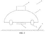
- FIG. 1 is a schematic diagram of an automatic working system 100 according to a first embodiment of the present invention.
- the automatic working system 100 in this embodiment of the present invention includes a self-moving device.
- the self-moving device may move and work in a working region defined in a map.
- the self-moving device is an automatic lawn mower 1.
- the self-moving device may alternatively be an unattended device including an automatic cleaning device, an automatic irrigation device, an automatic snowplow, or the like.
- the automatic lawn mower 1 includes a housing 3, a movement module 5, a task execution module 7, an energy module, a control module, and the like.
- the automatic lawn mower 1 works in a lawn 6.
- the movement module 5 includes a track or a wheel set, and is driven by a driving motor to drive the automatic lawn mower 1 to move.
- the task execution module 7 includes a cutting assembly, mounted at the bottom of the housing 3 and driven by a cutting motor to rotate to perform mowing.
- the energy module includes a battery pack (not shown in the figure), which provides electric energy for movement and working of the automatic lawn mower 1.
- the control module is electrically connected to the movement module 5, the task execution module 7, and the energy module, controls the movement module to drive the automatic lawn mower 1 to move, and controls the task execution module to perform a working task.
- the automatic working system is configured to work in a predetermined working region.
- the working region includes at least two separated sub-working regions, that is, a region C and a region D.
- a boundary 8 is formed between the working region and a non-working region, and there may be obstacles such as trees or pits in the working region.
- the automatic working system 100 further includes a charging station 2, configured to supply electric energy to the automatic lawn mower 1.
- the charging station 2 may be arranged in an open place beside a house 4.
- the charging station 2 may alternatively be arranged in the working region or arranged on a boundary of the working region.
- the automatic working system 100 includes a navigation module, configured to output a current position of the automatic lawn mower.
- the navigation module includes a mobile station 9.
- the automatic working system 100 further includes a reference point A and a reference point B arranged in the working region.
- the reference point A, the reference point B, and the charging station 2 may be all used as reference positions.
- the reference position is an open position, and the satellite signal has relatively high quality.
- the mobile station 9 is electrically connected to the control module, and is configured to store and process a satellite signal obtained by the automatic lawn mower 1, so that the automatic lawn mower 1 can move and work in the working region.
- the mobile station 9 is configured to receive the satellite signal.
- the satellite signal includes a satellite angle, a clock, and the like.
- the satellite signal may be a GPS signal, or may be a Galileo signal or a Beidou signal, or may use several signals simultaneously.
- the satellite signal is a differential GPS (DGPS) signal, a GPS-RTK signal, or the like.
- DGPS differential GPS
- the navigation module may output an accuracy level of a positioning signal.
- the accuracy level of the positioning signal is a positioning signal quality parameter described below.
- the automatic lawn mower 1 may also determine a current positioning state according to the position information outputted by the navigation module, and output a positioning state indication.
- Quality of the position information outputted by the navigation module may be determined based on a quantity of satellites from which the navigation module can receive signals, or the positioning state indication, or an accuracy factor, or a combination of a plurality of factors.
- An importance weight is set to obtain the quality of the position information.
- Error evaluation for the quality of the position information outputted by the navigation module may be performed by the navigation module itself, and the control module obtains an evaluation result, or the control module may perform error evaluation by using an output of the navigation module, to obtain an evaluation result.
- the automatic lawn mower 1 further includes at least one position sensor, electrically connected to the control module, and configured to detect a feature related to a position of the automatic lawn mower 1.
- the position sensor may include a camera, a radar, a capacitive sensor, an inertial navigation sensor, and the like.
- the position sensor is the inertial navigation sensor.
- the inertial navigation sensor may include an accelerometer, an odometer, a compass, a gyroscope, a posture detection sensor, and the like, and is configured to detect a speed, an acceleration, a moving direction, and the like of the self-moving device.
- the control module determines a current position of the automatic lawn mower 1 at least partially based on an output of the position sensor.
- the position information outputted by the navigation module and the output of the position sensor may be fused, to obtain the current position of the automatic lawn mower.
- the inertial navigation sensor is used as an example, if the inertial navigation sensor is continuously used for navigation, an error of an output of the inertial navigation sensor accumulates over time, resulting in a decrease in the accuracy of the outputted position information. Therefore, when the quality of the position information outputted by the navigation module meets the preset condition, the output of the position sensor is corrected by using an output of a satellite navigation apparatus, so that the position sensor can maintain a high-precision output.
- navigation when the mobile station 9 works, navigation may be performed by using only a GPS positioning signal, or navigation may be performed by using a positioning signal obtained after a GPS positioning signal and inertial navigation data are fused, or navigation may be performed by using only inertial navigation data when a GPS signal is weak.
- the mobile station 9 may further include an indicator (not shown in the figure), configured to output an indication indicating whether a differential GPS signal at a current position is good or not.
- the mobile station 9 may be detachably connected to the housing 3 of the automatic lawn mower 1.
- the mobile station 9 includes a first interface (not shown in the figure) connected to the housing of the automatic lawn mower 1.
- the mobile station 9 is mounted on the housing 3 of the automatic lawn mower 1.
- the mobile station 9 may be electrically connected to the control module of the automatic lawn mower 1.
- the mobile station 9 outputs coordinates of a current position of the automatic lawn mower 1, and the control module controls movement and working of the automatic lawn mower 1 according to the current position of the automatic lawn mower 1.
- the mobile station outputs a control instruction to the control module according to coordinates of a current position.
- the mobile station 9 includes an independent power supply module (not shown in the figure).
- the mobile station 9 may works independently when being separated from the housing 3 of the automatic lawn mower 1.
- the mobile station 9 may be non-detachably connected to the housing 3 of the automatic lawn mower 1. If positioning is performed during working of the self-moving device, whether the mobile station 9 and the housing 3 of the automatic lawn mower 1 are detachable does not affect positioning.
- the mobile station 9 obtains error data by using a reference positioning signal before a current positioning signal, and obtains current position information based on processing of the error data and position information of the reference positioning signal, without using a satellite signal received in real time by a self-built base station or a shared base station at a current moment. Therefore, the self-built base station or the shared base station may be canceled, to simplify user mounting, thereby greatly reducing costs.
- a shadow region There may be some regions with weak satellite navigation signals in a working region, for example, a shadow region.
- the navigation accuracy may be affected, and further a navigation effect of the automatic lawn mower is affected.
- the navigation accuracy of the automatic lawn mower may be assisted by using an inertial navigation system.
- an error of inertial navigation accumulates over time.
- the accumulated error of the inertial navigation may be corrected by using positioning coordinates of a satellite navigation system after the inertial navigation system works for a period of time, to ensure the navigation accuracy of the self-moving device in the shadow region.
- a positioning apparatus of the self-moving device may be arranged in a server or may be arranged in the mobile station. This is not limited in this embodiment of this application.
- the electronic device is, for example, a personal computer (PC), a cloud device, or a mobile device.
- the mobile device is, for example, a smartphone or a tablet computer.
- an execution body may be, for example, a central processing unit (CPU) in a server or the electronic device on hardware, or may be, for example, a background management service in a server or the electronic device on software, which is not limited.
- CPU central processing unit
- an entity base station that is, a self-built base station or a shared base station.
- the self-built base station or the shared base station may provide a real-time satellite signal for positioning to the self-moving device as a reference positioning signal.
- the mobile station 9 performs calculation processing by using real-time satellite data obtained by the entity base station to obtain current position information without an accumulated error, and from the perspective of a satellite signal, it is considered that a positioning error is a constant value or an error difference is relatively small.
- a virtual base station is adopted, that is, any self-built base station or shared base station that can obtain a real-time satellite signal is not arranged, and only a satellite signal of a reference point obtained at a time point is used as a reference positioning signal for subsequent positioning.
- a satellite signal obtained before the self-moving device departs is used as the reference positioning signal for subsequent positioning.
- a satellite signal that meets a calculation condition before a current positioning signal may further be used as the reference positioning signal. In this positioning manner, because a positioning error is an accumulated error, the error is gradually increased over time.
- the self-moving device sets error evaluation.
- the self-moving device is controlled to return to a reference point to re-obtain a satellite signal at a reference point position.
- the satellite signal is used as a new reference positioning signal for positi oning.
- a staying time of the automatic lawn mower in the shadow region may be controlled by effectively recognizing the shadow region, so that the staying time of the automatic lawn mower in the shadow region can be effectively controlled, and the positioning accuracy of the automatic lawn mower in the working region can be greatly improved.
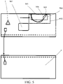
- the automatic lawn mower 1 has a mapping boundary 901 obtained by mapping.
- the working region is divided into four parts, which are respectively a region C, a region D, a region E, and a region F.
- a mapping manner may be that, for example, a user circles a working region of the self-moving device on Google Map, the mobile station 9 and the self-moving device are in integrated arrangement, and the self-moving device works around the working region by one circle.
- the self-moving device is an automatic lawn mower
- the user may push the automatic lawn mower to work, the user may remotely control the automatic lawn mower to work, the automatic lawn mower may follow a track of a movement of the user, the automatic lawn mower may work automatically, or the like, which is not limited.
- the mapping boundary 901 is a boundary on a map or a boundary obtained during walking.
- a working region map is generated by collecting basic position data of the working region.
- the basic position data is obtained by using the navigation module of the self-moving device through a manual operation. For example, the user holds a navigation module (or a navigation device) to walk around an actual boundary of the working region by one circle, to obtain the basic position data.
- a shadow region 30 is formed.
- a satellite signal received in the shadow region is relatively weak during mapping, resulting in inaccurate positioning of this section of boundary in the mapping boundary 901, and this section of boundary with inaccurate positioning may be marked as an initial shadow region.
- the automatic lawn mower may be controlled to move toward the working region along an assumption boundary 904 of the shadow region.
- the shadow region needs to be first effectively recognized.
- the self-moving device may start from a virtual initial position 908 and move toward the initial shadow region to explore the shadow region.
- An exploring route may be parallel to an extending direction of the boundary, may be perpendicular to an extending direction of the boundary, or may be inclined relative to an extending direction of the boundary.
- a shadow region exploration boundary 905 may be obtained through exploration. It can be learned from the figure that the shadow region exploration boundary 905 obtained through the exploration may be very close to a shadow region actual boundary 906.
- a shadow region may be first explored, to make a map more accurate. In addition, the shadow region is first explored and then the shadow region is processed, to improve the positioning accuracy of the automatic lawn mower and improve a processing effect of the shadow region.
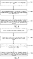
- FIG. 7 is a schematic flowchart of a map establishing method according to the present invention. As shown in FIG. 7 , the map establishing method includes step S101 to step S103.
- the working region map may be obtained according to collected basic position data of a working region.
- the basic position data is obtained through a manual operation.
- an automatic lawn mower is used as an example.
- the basic position data may be obtained by defining an initial boundary region on map software on an intelligent terminal such as a mobile phone, a tablet, or a computer.
- the map software may be Google Map, Baidu Map, or the like.
- a satellite map is displayed on the intelligent terminal, and a user finds a rough working region of the automatic lawn mower on the satellite map, frames and downloads the region, and then draws an initial boundary according to the actual working region, that is, collects boundary position data, to obtain an initial boundary region and store the initial boundary region as a map.
- Data in the stored map is position data corresponding to a boundary drawn on the satellite map.
- the automatic lawn mower includes a receiving apparatus.
- the mobile phone, the tablet, or the computer sends boundary position data related to the defined initial boundary region to the receiving apparatus of the automatic lawn mower.
- the receiving apparatus of the automatic lawn mower receives and stores the boundary position data related to the defined initial boundary region.
- the mobile phone, the tablet, or the computer sends a coordinate position of the defined initial boundary region to the receiving apparatus in a wireless or wired manner.
- the wireless manner includes Bluetooth, WiFi, or the like.
- the basic position data is obtained by using a navigation module of a self-moving device through a manual operation.
- the user holds a navigation module (or a navigation device) of the automatic lawn mower to walk around an actual boundary of a working region by one circle to obtain the basic position data.
- the initial shadow region includes an enlarged width from the initial shadow section to a working region.
- the scale width is in a range of 5% to 50% of a length value of the initial shadow section. For example, the scale width is 5% of the length value of the initial shadow section. If the initial shadow section is 20 m, the scale width is 1 m. For example, the scale width is 50% of the length value of the initial shadow section. If the initial shadow section is 20 m, the scale width is 10 m. For example, the scale width is 20% of the length value of the initial shadow section. If the initial shadow section is 20 m, the scale width is 4 m. For example, the scale width is 10% of the length value of the initial shadow section. If the initial shadow section is 20 m, the scale width is 2 m.
- the method further includes the following steps: determining whether a length value of the initial shadow section meets a preset condition, if the length value of the initial shadow section meets the preset condition, starting the step of generating an initial shadow region according to the initial shadow section, or otherwise, re-establishing the map.
- the preset condition is that the length value of the initial shadow section is less than or equal to 60 times a moving speed value of a self-moving device working in a working region. For example, if a moving speed of the self-moving device is 0.3 m/s, the length value of the initial shadow section cannot exceed 18 m, and if the length value exceeds 18 m, the map needs to be re-established. In another example, if the moving speed of the self-moving device is 0.5 m/s, the length value of the initial shadow section cannot exceed 30 m. If the length value exceeds the 30 m, the map needs to be re-established.
- the corrected shadow region is implemented by obtaining a positioning signal outputted by the navigation module of the self-moving device.
- the shadow region is a region in which the positioning signal outputted by the navigation module of the self-moving device does not meet a quality requirement.
- the self-moving device may obtain information about a boundary by using a map of a working region stored in the self-moving device.
- a user may hold a navigation device to walk around the boundary of the working region by one circle, to obtain the boundary in the map.
- a position in which boundary information is not clear in the map is obtained. Because a received satellite signal is relatively weak at the position in which the boundary information is not clear, a boundary position in the map is in complete or uncertain.
- the self-moving device performs shadow region exploration on the position in which the boundary information is not clear.
- a same method may be adopted for another obstacle forming a shadow region in the working region, that is, during initial mapping, a user holds a navigation device to walk around an obstacle to obtain a boundary of the obstacle. Because a satellite signal received in the shadow region is relatively weak, an obtained position of the boundary of the obstacle in the map is incomplete or uncertain.
- the self-moving device performs shadow region exploration on a position near the obstacle in which boundary information is not clear.
- correction for the working region map may be completed.
- the corrected shadow region feature points in which positioning signal quality parameters do not meet a set positioning signal quality threshold are obtained, a region range of the shadow region is obtained by connecting the feature points, and the map is corrected by using feature position data of the feature points, to improve the map.
- the self-moving device provided in this embodiment of the present invention can rapidly recognize a shadow region and improve a map, to lay a good foundation for the self-moving device to select a direction of entering the shadow region and also provide a basis for highly efficient working of the self-moving device.
- step S103 the exploring the shadow region of the working region specifically includes step S201 to step S203.
- the exploring the shadow region of the working region specifically includes step S301 to step S304.
- the initial shadow region is a region in which a positioning signal of a corresponding position on a working region map does not meet a quality requirement.
- the shadow region may be determined by comparing a detected positioning signal quality parameter with a preset positioning signal quality threshold.
- the threshold may be determined depending on whether accurate positioning can be performed by using a satellite signal. For example, when a machine may perform accurate positioning, even if GPS is weakened to a certain extent, it is still not necessary to determine that the self-moving device is located in the shadow region.
- a part of a region in which a satellite signal is weakened caused by the shielding of buildings or obstacles may be marked as a shadow region, so as to avoid possible increase in the workload of the machine due to the inability to divide the shadow region properly.
- the determining a boundary of the corrected shadow region includes the following steps:
- a method of the "recognizing a boundary point of the corrected shadow region in each direction according to the coordinate point” includes: recognizing a coordinate point closest to an exploration starting position in each direction, and using the coordinate point as the boundary point of the corrected shadow region.
- the method further includes step S 104 to step S106.
- the feature information of the shadow region includes a feature of a geometric shape defined by a shadow region boundary formed by outermost points in an explored shadow region.
- the feature information of the shadow region includes a feature of a highlighted geometric shape of an entire explored shadow region.
- a longitudinal long-axis may be defined for the shadow region after the geometric shape is obtained.
- the longitudinal long-axis is parallel to a long side direction of the rectangle, or the shadow region is of a roughly elliptical shape, the longitudinal long-axis is a major axis of the ellipse.
- the shadow region may be processed by using a mathematical method known in the art after being approximated into a regular shape, or a longitudinal long-axis may be determined by using another method, and then a subsequent step is performed based on the determined longitudinal long-axis.
- S105 Determine an entering direction in which a self-moving device enters the shadow region according to a feature of the shadow region.
- the shadow region includes a first edge roughly extending in an extending direction of a working region boundary and close to the working region boundary, and the entering direction is a direction along a rough normal to the first edge.
- the shadow region includes a first edge roughly extending in an extending direction of a working region boundary and close to the working region boundary, and the entering direction is a direction roughly parallel to the first edge.
- the entering direction is a direction roughly perpendicular to a longitudinal long-axis of the shadow region.
- the shadow region includes a first edge located at one side of a longitudinal long-axis of the shadow region, and the entering direction is a direction along a rough normal to the first edge.
- the shadow region includes a first edge close to an obstacle and a second edge away from the obstacle
- the entering direction includes a rough normal to the first edge or the second edge or the entering direction is a direction that minimizes a distance between the first edge and the second edge.
- the method may further include: presetting a positioning signal quality threshold in the self-moving device. Therefore, the detecting the shadow region in the working region includes: determining that the self-moving device is located in the shadow region according to a case that the obtained positioning signal quality parameter does not meet a quality requirement.
- the method further includes: making the self-moving device exit the shadow region in an exit direction opposite to the entering direction.
- a task for processing the shadow region can be completed. It may be understood that, shadow regions with different areas may be entered from different directions by using a plurality of the foregoing entering directions, to process the shadow region to a maximum extent.
- Roughly parallel/rough normal should be understood as relatively wide.
- the direction is within plus or minus 30° to a parallel direction/normal. In another optional embodiment, the direction is within plus or minus 20°, or 15°, or 10°, or 5°, or 3° to the parallel direction/normal.
- the selection principle of the direction can minimize time when the self-moving device is in the shadow region, to avoid the impact on the positioning accuracy of the self-moving device due to weak satellite signals.
- a direction in which the self-moving device enters the shadow region each time may be the same or may be different.
- the direction in which the self-moving device enters the shadow region may be determined according to the feature of the geometric shape of the shadow region.
- a direction in which the automatic lawn mower enters a same shadow region each time may be the same, to avoid giving the user a feeling of disordered operation of the automatic lawn mower, thereby improving the user experience.
- an edge of the shadow region 30 may be divided into a first edge 32 and a second edge 34 that are respectively located on two sides of the longitudinal long-axis.
- the shadow region 30 is defined by the first edge 32 and the second edge 34.
- the automatic lawn mower 1 may enter the shadow region 30 in a direction roughly perpendicular to the longitudinal long-axis or along a rough normal to the first edge 32 or the second edge 34. It may be understood that the direction is also a direction that minimizes a distance between the first edge and the second edge.
- the automatic lawn mower 1 may enter the shadow region 30 in the direction that minimizes the distance between the first edge 32 and the second edge 34.
- the automatic lawn mower 1 may select various directions to enter the shadow region 30. Compared with other directions, a direction to which a solid line arrow points is a shortest path from the second edge 34 to the first edge 32.
- the shortest distance herein is not limited to the absolute shortest, but is an optimal path from the second edge 34 to the first edge 32.
- the shortest distance may also be understood as a smallest average value of a moving distance of the automatic lawn mower 1 from the first edge 32 to the second edge 34 and a moving distance of the automatic lawn mower from the second edge 34 to the first edge 32 when the automatic lawn mower 1 completes cutting of the shadow region 30 in a path parallel to the entering direction.
- the shadow region in the working region is formed due to a building or another obstacle, so that signal weakening regions are formed on one or more sides of the building or the obstacle.
- the shape of the shadow region may be a shape extending outward from a lower edge of the building or the obstacle.
- the first edge 32 may be an intersection line of the building or the obstacle and a working region
- the second edge 34 may be formed by connecting points that are located near the building or the obstacle and of which signal quality parameters start meeting a preset threshold (the principle of the preset threshold is, for example, whether accurate navigation can be performed according to a strength of the satellite signal).
- the first edge 32 and the second edge 34 may surround to form a closed pattern.
- a semi-circular closed structure may be formed by the first edge and the second edge.
- the self-moving device may enter the shadow region in a direction along the rough normal to the first edge 32 or the second edge 34 or in the direction that minimizes the distance between the first edge 32 and the second edge 34.
- a walking path of the self-moving device may be set by a program.
- the program may simulate various walking manners of the self-moving device and determine a length of a path in which the self-moving device passes through the shadow region in a walking manner, to select a walking manner in which the self-moving device walks in the shadow region by using a shortest path.
- a walking direction of the self-moving device in a region may be consistent and continuous, that is, a direction is not adjusted with the small change of a shape of a boundary, to avoid giving the user an impression of "unintelligent".
- the shadow region is determined according to a strength of a satellite signal received by the self-moving device/the mobile station.
- a quality threshold of a received satellite signal may be preset, that is, the positioning signal quality threshold.
- the method further includes: presetting a positioning signal quality threshold in the self-moving device.
- the making the self-moving device enter the shadow region in the foregoing direction includes: enabling, by the self-moving device, an inertial navigation signal when a satellite signal quality parameter obtained by the self-moving device does not meet the positioning signal quality threshold; and recovering a satellite navigation signal when the satellite signal quality parameter obtained by the self-moving device meets the positioning signal quality threshold.
- the inertial navigation signal and the satellite navigation signal are switched based on the strength of the signal, to ensure accurate positioning of the machine.
- the making the self-moving device enter the shadow region in the foregoing direction includes: simultaneously enabling satellite navigation and inertial navigation; and using a weighted value of a satellite navigation result and an inertial navigation result as a navigation result.
- an error of the inertial navigation is gradually increased over time, resulting in increasingly low navigation accuracy.
- the inertial navigation and the satellite navigation may be combined to complement each other, to implement more accurate positioning of the machine in the shadow region.
- the satellite positioning device may alternatively be replaced by another positioning device, which is referred to as a first positioning device.
- the first positioning device outputs a first positioning signal.
- the first positioning device may further be an ultra-wideband (UWB) positioning device, an ultrasonic beacon positioning device, or the like.
- UWB ultra-wideband
- the inertial navigation device may alternatively be replaced by another positioning device, which is referred to as a second positioning device.
- the second positioning device outputs a second positioning signal.
- the second positioning device may further be an image acquisition device, a capacitive lawn detection device, or the like.
- the map establishing method further includes: presetting a time threshold in the shadow region; and controlling the self-moving device to enter the shadow region and exit the shadow region, so that a sum of an entering time of entering the shadow region and an exit time of exiting the shadow region meets the time threshold.
- the method may further include the following step S103 to step S106.
- the self-moving device after obtaining the working region map and the initial shadow region, the self-moving device ends mapping, enters a working process, and corrects the initial shadow region during working, to generate a corrected shadow region.
- a current mapping process may be first ended, and path planning is performed according to the working region map, to obtain a path planning graph shown in FIG. 16 .
- a dashed line 903 is a planned path, and the self-moving device is controlled to walk according to the path.
- the self-moving device detects the positioning signal quality parameter during walking. As shown in FIG.
- a positioning signal quality parameter of a current position when it is detected that a positioning signal quality parameter of a current position does not meet a signal quality threshold, it indicates that the current position is near a shadow region, so that the self-moving device may record coordinates of the current position and may be controlled to continue to walk.
- the positioning signal quality parameter does not meet the signal quality threshold may be that the self-moving device walks from a region with good signal quality to a region with poor signal quality such as a coordinate point A in FIG. 17 , or may be that the self-moving device walks from the region with poor signal quality to the region with good signal quality such as a coordinate point B in FIG. 17 .
- the self-moving device is controlled to enter the shadow region and exit the shadow region, so that a sum of an entering time of entering the shadow region and an exit time of exiting the shadow region meets the time threshold.
- a walking manner similar to the manner of performing working surface processing in the embodiment of the map establishing method may be adopted.
- the self-moving device when it is detected that recorded coordinates that do not meet the signal quality threshold reach a preset value (for example, ten), the self-moving device may be controlled to update the map.
- the self-moving device when it is detected that the self-moving device has walked through a complete working region, the self-moving device may be controlled to update the map.
- the map may be updated in the following manner, including:
- the map may be updated with reference to the initial shadow region and the boundary point, to obtain a corrected map.
- a boundary such as an exploration boundary 905 in FIG. 17 of the corrected shadow region is marked in the map. It should be noted that boundaries or paths in FIG. 17 are merely examples, which do not constitute a limitation on this application.
- a same method may be adopted for another obstacle forming a shadow region in the working region. That is, during working, the shadow region corresponding to the obstacle is explored in the manner. During subsequent working of the self-moving device, a similar manner may alternatively continue to be used to explore an encountered shadow region. This is not limited in this application.
- FIG. 13 is a schematic structural diagram of a self-moving device according to an embodiment of the present invention.
- the self-moving device further includes a map generation module 110, an exploration module 120, and a shadow region correction module 130.
- the map generation module 110 is configured to collect basic position data of a working region, generate a working region map and an initial shadow section, and generate an initial shadow region according to the initial shadow section.
- the exploration module 120 is configured to explore the initial shadow region within a working region range and collect positioning signal quality data and positioning coordinates during exploration, to generate a corrected shadow region.
- the shadow region correction module 130 is configured to generate the corrected shadow region according to the positioning signal quality data and the positioning coordinates, to correct the working region map.
- the map generation module 110 and the shadow region correction module 130 may include hardware such as a circuit structure and an input/output device, may include software such as a program implementing a function, or may include a combination of software and hardware provided that a specific function can be implemented.
- basic position data of a working region includes a boundary of the working region, or an obstacle (including an isolated island) in the working region, or a channel connecting different working regions, and further includes a position of a charging station, a path in which the automatic lawn mower leaves or returns to the charging station, and the like.
- the map generation module 110 or the shadow region correction module 130 may automatically collect the basic position data of the working region or may collect the basic position data of the working region through a manual operation.
- the basic position data of the working region is automatically collected by using the control module.
- the control module obtains a positioning signal outputted by a navigation module of a self-moving device and extracts the basic position data based on generation of the working region map.
- the basic position data of the working region may be collected by using an intelligent terminal through a manual operation.
- the map generation module 110 and the shadow region correction module 130 are communicatively connected to an external intelligent terminal.
- the external intelligent terminal may be a mobile phone, a tablet, or the like of a user.
- the map generation module 110 displays a satellite map in the intelligent terminal by using an existing satellite map such as Google Map or Baidu Map, and defines a working region manually defined by the user.
- An example in which a boundary of a working region is set is used for the following description of the steps. It may be understood that a manner of obtaining another feature position data of an obstacle in the working region is similar to the example.
- a satellite map is displayed on the intelligent terminal, and a user finds a rough working region of the automatic lawn mower on the satellite map, frames and downloads the region, then draws a boundary according to an actual working region, that is, collects boundary position data, and stores the boundary position data as a map.
- Data in the stored map is basic position data corresponding to a boundary drawn on the satellite map.
- the automatic working system includes application software.
- the application software is loaded on an external intelligent terminal, and a user obtains a satellite map by using the application software from the intelligent terminal and draws a boundary by using the application software, that is, collects boundary position data.
- the self-moving device further includes a navigation module, configured to output a positioning signal.
- the shadow region is a region in which the positioning signal outputted by the navigation module does not meet a quality requirement.
- the self-moving device further includes a signal quality obtaining module.
- the signal quality obtaining module is configured to obtain a positioning signal quality parameter obtained by the navigation module during movement of the self-moving device, and determine that the self-moving device is located in a shadow region according to a case that the obtained positioning signal quality parameter does not meet a set positioning signal quality threshold.
- the self-moving device further includes an initial shadow region obtaining module.
- the initial shadow region obtaining module is configured to obtain an initial shadow region in a working region.
- the control module controls the self-moving device to move toward the initial shadow region from different directions in the working region for exploring an actual area of the shadow region.
- the signal quality obtaining module obtains the positioning signal quality parameter outputted by the navigation module when the self-moving device moves toward the initial shadow region, and determines that the self-moving device is located in the shadow region according to the case that the obtained positioning signal quality parameter does not meet the set positioning signal quality threshold.
- the initial shadow region is a region in which a positioning signal quality parameter of a corresponding position on a working region map does not meet a positioning signal quality threshold.
- An actual area of the shadow region is explored, to provide a basis for the self-moving device to enter the shadow region for working subsequently, so that the self-moving device plans a direction of entering the shadow region and a time of entering the shadow region, and the self-moving device may select an optimal entering direction (which may be a plurality of directions) and set a suitable shadow region staying time according to the actual area of the shadow region, to ensure the positioning accuracy of the self-moving device and improve the processing efficiency and effect of the shadow region.
- the initial shadow region obtaining module may move toward the initial shadow region within a working region range, detect feature points in which positioning signal quality parameters do not meet the positioning signal quality threshold, and obtain an explored shape of the shadow region by connecting the feature points.
- the self-moving device provided in this embodiment of the present invention can rapidly recognize a shadow region, to lay a good foundation for the self-moving device to select a suitable direction of entering the shadow region and planning of a plurality of directions.
- control module is configured to recognize feature information of the shadow region, determine an entering direction in which the self-moving device enters the shadow region according to a feature of the shadow region, and make the self-moving device enter the shadow region in the entering direction.
- control module is configured to recognize a boundary of the shadow region, determine an entering direction in which the self-moving device enters the shadow region according to a boundary feature of the shadow region, and make the self-moving device enter the shadow region in the entering direction.
- an actual range of a shadow region is first explored, and then a direction in which the self-moving device enters the shadow region is selected according to a shadow region boundary obtained through exploration. With such arrangement, a staying time of the self-moving device in the shadow region can be effectively controlled, a processing mode of the shadow region can be reasonably planned, and the positioning accuracy of the self-moving device can be improved.
- a method for correcting a shadow region by using the exploration module 120 may include: determining a shadow region by detecting a strength of a satellite signal. Specifically, an initial shadow region may be obtained by initial mapping.
- a specific method is that a positioning signal quality threshold of a received differential GPS signal is set in the control module, and the self-moving device walks around, for example, a building (or a differential GPS mobile station is removed manually and the mobile station is carried to move around a position of a boundary of a signal strength, points in which a signal strength does not meet a quality threshold are recorded, and then the points are connected, to obtain a shape of a shadow region), so that points in which positioning signal quality parameters are less than or equal to a preset positioning signal quality threshold are marked in a map, and after sufficient feature signal point are selected, the points on the boundary may be connected, to obtain the initial shadow region.
- the establishing of the initial shadow region is limited to a manual walking position in most cases. Because during initial mapping, people generally walk along a working region boundary or a boundary of an obstacle by one circle, an area of the obtained initial shadow region is very small.
- the control module may control the self-moving device to adjust a posture by using a current position and posture information of the self-moving device and a shape defined by a boundary of a shadow region and position information of the shadow region when the self-moving device reaches an edge outside the shadow region, so that the self-moving device enters the shadow region in a specific direction, or adjust an entire walking direction of the self-moving device in this region according to a shape defined by a boundary of a shadow region in this region, so that the self-moving device walks continuously.
- the shadow region includes a first edge roughly extending in an extending direction of a working region boundary and close to the working region boundary, and the entering direction is a direction along a rough normal to the first edge.
- the shadow region includes a first edge roughly extending in an extending direction of a working region boundary and close to the working region boundary, and the entering direction is a direction roughly parallel to the first edge.
- the entering direction is a direction roughly perpendicular to a longitudinal long-axis of the shadow region.
- the shadow region includes a first edge located at one side of a longitudinal long-axis of the shadow region, and the entering direction is a direction along a rough normal to the first edge.
- the shadow region includes a first edge close to an obstacle and a second edge away from the obstacle
- the entering direction includes a direction along a rough normal to the first edge or the second edge or the entering direction is a direction that minimizes a distance between the first edge and the second edge.
- the self-moving device travels in a direction roughly perpendicular to a longitudinal long-axis of the shadow region, or along a rough normal to a first edge or a second edge, or in a direction that minimizes a distance between the first edge and the second edge. It may be understood that, compared with traveling in another direction, a traveling distance of the self-moving device in the shadow region is relatively short, an accumulated error is relatively small, and the positioning is more accurate.
- shadow regions with different areas may be entered from different directions by using a plurality of entering directions, to process the shadow region to a maximum extent.
- Roughly parallel/rough normal should be understood as relatively wide.
- the direction is within plus or minus 30° to a parallel direction/normal. In another optional embodiment, the direction is within plus or minus 20°, or 15°, or 10°, or 5°, or 3° to the parallel direction/normal.
- the selection principle of the direction can minimize a time when the self-moving device is in the shadow region, to avoid the impact on the positioning accuracy of the self-moving device due to weak satellite signals.
- a direction in which the self-moving device enters the shadow region each time may be the same or may be different.
- the direction in which the self-moving device enters the shadow region may be determined according to the feature of the geometric shape of the shadow region.
- a direction in which the automatic lawn mower enters a same shadow region each time may be the same, to avoid giving the user a feeling of disordered operation of the automatic lawn mower, thereby improving the user experience.
- the control module makes the self-moving device exit the shadow region in an exit direction opposite to the entering direction.
- the self-moving device further includes a time presetting module.
- the time presetting module is configured to preset a time threshold of the self-moving device in the shadow region, where the control module controls the self-moving device to enter the shadow region and exit the shadow region, so that a sum of an entering time of entering the shadow region and an exit time of exiting the shadow region meets the time threshold.
- the mobile station 9 further includes an auxiliary positioning apparatus.
- the auxiliary positioning apparatus includes a pedometer, a laser radar, a camera, an odometer, an ultrasonic wave, and the like.
- the inertial navigation apparatus may also be considered as an auxiliary positioning apparatus.
- the auxiliary positioning apparatus is configured to match differential GPS positioning when a differential GPS signal is poor. A positioning error is corrected by using a correction value outputted by the auxiliary positioning apparatus, so that the accuracy of a generated map is higher.
- the mobile station 9 includes a path generation module, configured to generate path planning according to the working region map.
- a working region is divided according to a boundary, an obstacle, a channel, or the like of the working region.
- the division of the working region makes coverage of the automatic lawn mower more efficient.
- the working region is divided into two sub-working regions connected by a channel.
- the automatic lawn mower covers one sub-working region, and then enters the other sub-working region through the channel. In this manner, low efficient working caused by that the automatic lawn mower moves back and forth between two ends of the channel is avoided.
- two parts in the working region separated by an obstacle are divided into two sub-regions, to prevent the automatic lawn mower from encountering the obstacle frequently.
- a part with a regular boundary shape and a part with an irregular boundary shape may further be divided into different sub-regions according to a boundary shape.
- the automatic lawn mower may cover a regular sub-region according to a regular path and cover an irregular sub-region according to a random path.
- adjacent sub-regions have an overlapping part, to prevent a part between the adjacent sub-regions from being unable to be covered.
- a size of a partition is determined by estimating an area of a region in which a battery pack is used for working once according to a battery pack level.
- partitioning may further be performed according to a plant growth condition, so that the automatic lawn mower has a high cutting power and a long cutting time when being in a region with lush plants, and has a low cutting power and a short cutting time when being in a region with sparse plants.
- partitioning may further be performed according to a degree of importance of a region. For example, a front yard and a back yard of the user are divided into different sub-regions, so that the automatic lawn mower works in the front yard and the back yard by using different working policies.
- partitioning may further be performed according to comprehensive factors such as a quantity of obstacles.
- a path of the automatic lawn mower in each sub-region is planned.
- a preset path of the automatic lawn mower in each sub-region may be a regular path such as a parallel path or a spiral path, or may be a random path.
- a computer-readable storage medium is provided, storing computer program instructions, the computer program instructions, when executed by a processor, making the processor perform steps of the "map establishing method" in this specification.
- the computer-readable storage medium may use any combination of one or more readable media.
- the readable medium may be a readable signal medium or a readable storage medium.
- the readable storage medium may be, for example, but is not limited to, an electric, magnetic, optical, electromagnetic, infrared, or semi-conductive system, apparatus, or device, or any combination thereof. More specific examples of the readable storage medium (a non-exhaustive list) include: an electrical connection having one or more wires, a portable disk, a hard disk, a random access memory (RAM), a read-only memory (ROM), an erasable programmable ROM (EPROM or a flash memory), an optical fiber, a CD-ROM, an optical storage device, a magnetic storage device, or any appropriate combination thereof.
- the present invention further provides a computer program product, where when instructions in the computer program product are executed by a processor, the map establishing method is implemented, the method including:
- a computer program product including computer program instructions, where the computer program instructions, when being executed by a processor, make the processor perform the steps of the "map establishing method" in this specification.
- the computer program product may write the program code used for executing the operations of this application by using one or more programming languages or a combination thereof.
- the programming languages include an object-oriented programming language such as Java, C++ and the like, and also include a conventional procedural programming language such as "C" or similar programming languages.
- the program code may be completely executed on a user computing device, partially executed on a user device, executed as an independent software package, partially executed on a user computing device and partially executed on a remote computing device, or completely executed on a remote computing device or server.
- the present invention further provides an electronic device, including:
- the electronic device may be an electronic device integrated in a mobile station of the self-moving device or a stand-alone device independent of the mobile station.
- the stand-alone device may communicate with the mobile station to implement the map establishing method according to an embodiment of the present invention.
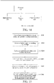
- FIG. 14 is a schematic block diagram of an electronic device according to an embodiment of the present invention.
- the electronic device 600 includes one or more processors 610 and a memory 620.
- the processor 610 may be a central processing unit (CPU) or another form of processing unit with data processing capabilities and/or instruction execution capabilities, and may control other components in the electronic device 600 to perform desired functions.
- the memory 620 may include one or more computer program products, and the computer program products may include various forms of computer-readable storage media, for example, a volatile memory and/or a non-volatile memory.
- the volatile memory may include a random access memory (RAM) and/or a high-speed cache.
- RAM random access memory
- the non-volatile memory may include a ROM, a hard disk, and a flash memory.
- the processor 610 may run the program instructions, to implement the map establishing method and/or another expected function of the self-moving device according to the embodiments of the present invention.
- the computer-readable storage medium may further store content such as position data of antenna and a mounting position of the antenna relative to the self-moving device.
- the electronic device 600 may further include: an input apparatus 630 and an output apparatus 640. These components are interconnected by a bus system and/or other forms of connection mechanisms (not shown).
- the input apparatus 630 may be configured to receive user inputs.
- the output apparatus 640 may directly output various information to the outside, or control the mobile station to transmit signals.
- FIG. 14 merely shows some of the components related to this application in the electronic device 600, and omits the components such as the bus, input/output interfaces, and the like.
- the electronic device 600 may also include any other appropriate components according to specific application conditions.
- each part of the present invention may be implemented by hardware, software, firmware, or a combination thereof.
- a plurality of steps or methods may be implemented by using software or firmware that are stored in a memory and are executed by a proper instruction execution system.
- the plurality of steps or methods may be implemented by any one of following common technologies in the art or a combination thereof: a discrete logic circuit of a logic gate circuit for realizing a logic function for a data signal, an application specific integrated circuit having a suitable combined logic gate circuit, a programmable gate array (PGA), and a field programmable gate array (FPGA).
- PGA programmable gate array
- FPGA field programmable gate array
- each functional unit in each embodiment of the present invention may be integrated into one processing module, or each unit may exist alone physically, or two or more units may be integrated into one module.
- the integrated module may be implemented in the form of hardware, or may be implemented in a form of a software functional module. If implemented in the form of software functional modules and sold or used as an independent product, the integrated module may also be stored in a computer-readable storage medium.
Landscapes
- Engineering & Computer Science (AREA)
- Radar, Positioning & Navigation (AREA)
- Remote Sensing (AREA)
- Physics & Mathematics (AREA)
- Automation & Control Theory (AREA)
- General Physics & Mathematics (AREA)
- Aviation & Aerospace Engineering (AREA)
- Life Sciences & Earth Sciences (AREA)
- Environmental Sciences (AREA)
- Control Of Position, Course, Altitude, Or Attitude Of Moving Bodies (AREA)
- Quality & Reliability (AREA)
- Electromagnetism (AREA)
- Computer Networks & Wireless Communication (AREA)
- Signal Processing (AREA)
Applications Claiming Priority (2)
| Application Number | Priority Date | Filing Date | Title |
|---|---|---|---|
| CN201910930354.9A CN112578779A (zh) | 2019-09-29 | 2019-09-29 | 地图建立方法、自移动设备、自动工作系统 |
| PCT/CN2020/118908 WO2021058032A1 (zh) | 2019-09-29 | 2020-09-29 | 地图建立方法、自移动设备、自动工作系统 |
Publications (3)
| Publication Number | Publication Date |
|---|---|
| EP4043984A1 true EP4043984A1 (de) | 2022-08-17 |
| EP4043984A4 EP4043984A4 (de) | 2023-09-06 |
| EP4043984B1 EP4043984B1 (de) | 2025-04-09 |
Family
ID=75110353
Family Applications (1)
| Application Number | Title | Priority Date | Filing Date |
|---|---|---|---|
| EP20869776.3A Active EP4043984B1 (de) | 2019-09-29 | 2020-09-29 | Kartenbauverfahren, selbstbewegende vorrichtung und automatisches arbeitssystem |
Country Status (4)
| Country | Link |
|---|---|
| US (1) | US12153440B2 (de) |
| EP (1) | EP4043984B1 (de) |
| CN (1) | CN112578779A (de) |
| WO (1) | WO2021058032A1 (de) |
Cited By (1)
| Publication number | Priority date | Publication date | Assignee | Title |
|---|---|---|---|---|
| WO2025096492A1 (en) * | 2023-10-31 | 2025-05-08 | The Toro Company | Assessing a work site for autonomous navigability |
Families Citing this family (27)
| Publication number | Priority date | Publication date | Assignee | Title |
|---|---|---|---|---|
| CN112578779A (zh) * | 2019-09-29 | 2021-03-30 | 苏州宝时得电动工具有限公司 | 地图建立方法、自移动设备、自动工作系统 |
| JP2022076339A (ja) * | 2020-11-09 | 2022-05-19 | 本田技研工業株式会社 | 作業機および情報管理装置 |
| WO2022159499A1 (en) * | 2021-01-19 | 2022-07-28 | Taha Ayman | Technician performance system |
| SE544856C2 (en) * | 2021-04-13 | 2022-12-13 | Husqvarna Ab | System and method for determining operating boundaries of a robotic work tool |
| CN115248588A (zh) * | 2021-04-27 | 2022-10-28 | 南京泉峰科技有限公司 | 自移动设备及其运动控制方法 |
| SE545830C2 (en) * | 2021-05-03 | 2024-02-13 | Husqvarna Ab | System and method for operating a robotic work tool in a first and a second work area |
| CN113110497B (zh) * | 2021-05-08 | 2024-06-18 | 珠海一微半导体股份有限公司 | 基于导航路径的沿边绕障路径选择方法、芯片及机器人 |
| CN115342804A (zh) * | 2021-05-14 | 2022-11-15 | 苏州宝时得电动工具有限公司 | 一种生成工作地图的方法、装置和自移动设备 |
| CN114115363B (zh) * | 2021-12-04 | 2023-07-18 | 中国人民解放军国防科技大学 | 一种基于动态目标追踪的多无人机未知室内空间探索方法 |
| CN116466693B (zh) * | 2022-01-11 | 2025-11-07 | 未岚大陆(北京)科技股份有限公司 | 地图处理方法、自移动的园艺设备、以及自动割草机 |
| CN116893665B (zh) * | 2022-04-11 | 2026-02-27 | 苏州宝时得电动工具有限公司 | 作业设备的工作边界的确定方法、装置、存储介质 |
| EP4268565B1 (de) * | 2022-04-28 | 2024-04-17 | Husqvarna AB | Verbesserte navigation für ein robotisches arbeitswerkzeugsystem |
| SE546505C2 (en) * | 2022-06-13 | 2024-11-19 | Husqvarna Ab | Improved navigation for a robotic work tool system using reliably received satellites |
| CN115016498B (zh) | 2022-07-05 | 2023-07-11 | 未岚大陆(北京)科技有限公司 | 割草机的建图方法、装置、存储介质及割草机 |
| CN115265601B (zh) * | 2022-07-27 | 2026-01-27 | 格力博(江苏)股份有限公司 | 一种园林工具导航信息校准方法、装置及园林工具 |
| CN115309764A (zh) * | 2022-08-30 | 2022-11-08 | 深圳市正浩创新科技股份有限公司 | 地图传输方法、地图构建方法、地图构建系统以及介质 |
| CN115423961A (zh) * | 2022-09-15 | 2022-12-02 | 深圳市正浩创新科技股份有限公司 | 地图构建方法及装置、自移动设备、计算机可读存储介质 |
| CN115509227A (zh) * | 2022-09-16 | 2022-12-23 | 未岚大陆(北京)科技有限公司 | 自主移动设备的控制方法和相关设备 |
| EP4645015A1 (de) * | 2022-12-30 | 2025-11-05 | Positec Power Tools (Suzhou) Co., Ltd. | Verfahren und vorrichtung zur bestimmung der arbeitsgrenze einer betriebsvorrichtung und speichermedium |
| WO2024179481A1 (zh) * | 2023-02-28 | 2024-09-06 | 苏州宝时得电动工具有限公司 | 自移动设备及控制方法、自主工作系统 |
| CN119148693A (zh) * | 2023-06-12 | 2024-12-17 | 苏州宝时得电动工具有限公司 | 自移动设备的控制方法、自移动设备及存储介质 |
| CN119536243A (zh) * | 2023-08-29 | 2025-02-28 | 苏州宝时得电动工具有限公司 | 作业控制方法、自移动割草设备及可读存储介质 |
| CN119620743B (zh) * | 2023-09-13 | 2026-03-20 | 苏州宝时得电动工具有限公司 | 自移动设备的控制方法、自移动设备 |
| CN117707138A (zh) * | 2023-11-13 | 2024-03-15 | 深圳库犸科技有限公司 | 自移动设备控制方法、自移动设备及存储介质 |
| EP4589399A1 (de) * | 2024-01-17 | 2025-07-23 | Husqvarna AB | Verbesserte planung für ein robotisches arbeitswerkzeug |
| CN118370073B (zh) * | 2024-03-27 | 2026-02-10 | 江苏东成机电工具有限公司 | 自移动设备出边界保护方法及系统 |
| CN119296236B (zh) * | 2024-10-28 | 2025-08-08 | 广东小狼星物联有限公司 | 一种适用于幼童防走失的地理围栏创建方法及系统 |
Family Cites Families (16)
| Publication number | Priority date | Publication date | Assignee | Title |
|---|---|---|---|---|
| JP2007175286A (ja) * | 2005-12-28 | 2007-07-12 | Funai Electric Co Ltd | 自動掃除システム |
| CN203609373U (zh) * | 2013-11-20 | 2014-05-28 | 苏州科沃斯商用机器人有限公司 | 带有矫正装置的自移动机器人 |
| WO2015085483A1 (en) * | 2013-12-10 | 2015-06-18 | SZ DJI Technology Co., Ltd. | Sensor fusion |
| US9720417B2 (en) * | 2013-12-19 | 2017-08-01 | Husqvarna Ab | Navigation for a robotic working tool |
| JP5976700B2 (ja) * | 2014-01-22 | 2016-08-24 | 日立建機株式会社 | 地図生成システム |
| US9516806B2 (en) * | 2014-10-10 | 2016-12-13 | Irobot Corporation | Robotic lawn mowing boundary determination |
| WO2016097891A1 (en) * | 2014-12-18 | 2016-06-23 | Husqvarna Ab | Robotic vehicle for detecting gps shadow zones |
| US10021529B2 (en) * | 2015-04-21 | 2018-07-10 | Hewlett Packard Enterprise Development Lp | Calibration of wireless network's signal strength map database for indoor locating techniques |
| US9818303B2 (en) * | 2015-06-16 | 2017-11-14 | Verizon Patent And Licensing Inc. | Dynamic navigation of UAVs using three dimensional network coverage information |
| JP6849330B2 (ja) * | 2015-08-28 | 2021-03-24 | パナソニック インテレクチュアル プロパティ コーポレーション オブ アメリカPanasonic Intellectual Property Corporation of America | 地図生成方法、自己位置推定方法、ロボットシステム、およびロボット |
| WO2017167207A1 (zh) | 2016-03-29 | 2017-10-05 | 苏州宝时得电动工具有限公司 | 自动工作系统及其工作区域的地图建立方法 |
| CN106155053A (zh) * | 2016-06-24 | 2016-11-23 | 桑斌修 | 一种割草方法、装置以及系统 |
| CN108227704A (zh) * | 2016-12-15 | 2018-06-29 | 苏州宝时得电动工具有限公司 | 自移动设备及其移动方法、存储介质和服务器 |
| US20190041225A1 (en) * | 2017-08-04 | 2019-02-07 | Walmart Apollo, Llc | Systems, devices, and methods for generating vehicle routes within signal coverage zones |
| KR102070068B1 (ko) | 2017-11-30 | 2020-03-23 | 엘지전자 주식회사 | 이동 로봇 및 그 제어방법 |
| CN112578779A (zh) * | 2019-09-29 | 2021-03-30 | 苏州宝时得电动工具有限公司 | 地图建立方法、自移动设备、自动工作系统 |
-
2019
- 2019-09-29 CN CN201910930354.9A patent/CN112578779A/zh active Pending
-
2020
- 2020-09-29 US US17/764,888 patent/US12153440B2/en active Active
- 2020-09-29 WO PCT/CN2020/118908 patent/WO2021058032A1/zh not_active Ceased
- 2020-09-29 EP EP20869776.3A patent/EP4043984B1/de active Active
Cited By (1)
| Publication number | Priority date | Publication date | Assignee | Title |
|---|---|---|---|---|
| WO2025096492A1 (en) * | 2023-10-31 | 2025-05-08 | The Toro Company | Assessing a work site for autonomous navigability |
Also Published As
| Publication number | Publication date |
|---|---|
| EP4043984B1 (de) | 2025-04-09 |
| EP4043984A4 (de) | 2023-09-06 |
| WO2021058032A1 (zh) | 2021-04-01 |
| CN112578779A (zh) | 2021-03-30 |
| US20220342426A1 (en) | 2022-10-27 |
| US12153440B2 (en) | 2024-11-26 |
Similar Documents
| Publication | Publication Date | Title |
|---|---|---|
| EP4043984B1 (de) | Kartenbauverfahren, selbstbewegende vorrichtung und automatisches arbeitssystem | |
| CN108398944B (zh) | 自移动设备的作业方法、自移动设备、存储器和服务器 | |
| US12061476B2 (en) | Returning method of self-moving device, self-moving device, storage medium, and server | |
| CN113126613B (zh) | 智能割草系统及其自主建图方法 | |
| EP4020112B1 (de) | Robotermäher und steuerungsverfahren dafür | |
| US11442466B2 (en) | Automatic working system, self-moving device, and methods for controlling same | |
| CN110320860A (zh) | 自移动设备及其工作系统、及其自动排程方法和计算面积的方法 | |
| CN112578780A (zh) | 自移动设备及其控制方法、自动工作系统 | |
| WO2024055855A1 (en) | Autonomous mobile device and method for controlling the same, and computer readable storage medium | |
| WO2024179496A1 (zh) | 一种控制方法、控制装置、存储介质及自移动设备 | |
| KR20200101529A (ko) | 이동 로봇 및 이의 제어 방법 | |
| CN114510010A (zh) | 机器人自动充电方法、系统,机器人及存储介质 | |
| CN117570827A (zh) | 回充定位方法、系统、自移动设备及可读存储介质 | |
| CN120836021A (zh) | 自移动设备的控制方法、装置及自移动设备 | |
| EP4653971A1 (de) | Betriebsverfahren für autonome betriebsvorrichtung und autonome betriebsvorrichtung | |
| CN115933681A (zh) | 基于激光和视觉方案的工作区域圈定方法及室外机器人 | |
| CN120380924A (zh) | 自移动割草机和自移动割草机的建边方法 |
Legal Events
| Date | Code | Title | Description |
|---|---|---|---|
| STAA | Information on the status of an ep patent application or granted ep patent |
Free format text: STATUS: THE INTERNATIONAL PUBLICATION HAS BEEN MADE |
|
| PUAI | Public reference made under article 153(3) epc to a published international application that has entered the european phase |
Free format text: ORIGINAL CODE: 0009012 |
|
| STAA | Information on the status of an ep patent application or granted ep patent |
Free format text: STATUS: REQUEST FOR EXAMINATION WAS MADE |
|
| 17P | Request for examination filed |
Effective date: 20220428 |
|
| AK | Designated contracting states |
Kind code of ref document: A1 Designated state(s): AL AT BE BG CH CY CZ DE DK EE ES FI FR GB GR HR HU IE IS IT LI LT LU LV MC MK MT NL NO PL PT RO RS SE SI SK SM TR |
|
| DAV | Request for validation of the european patent (deleted) | ||
| DAX | Request for extension of the european patent (deleted) | ||
| A4 | Supplementary search report drawn up and despatched |
Effective date: 20230808 |
|
| RIC1 | Information provided on ipc code assigned before grant |
Ipc: G05D 1/02 20200101AFI20230802BHEP |
|
| P01 | Opt-out of the competence of the unified patent court (upc) registered |
Effective date: 20240312 |
|
| STAA | Information on the status of an ep patent application or granted ep patent |
Free format text: STATUS: EXAMINATION IS IN PROGRESS |
|
| 17Q | First examination report despatched |
Effective date: 20240510 |
|
| REG | Reference to a national code |
Ref country code: DE Ref legal event code: R079 Free format text: PREVIOUS MAIN CLASS: G05D0001020000 Ipc: G05D0001000000 Ref country code: DE Ref legal event code: R079 Ref document number: 602020049287 Country of ref document: DE Free format text: PREVIOUS MAIN CLASS: G05D0001020000 Ipc: G05D0001000000 |
|
| GRAP | Despatch of communication of intention to grant a patent |
Free format text: ORIGINAL CODE: EPIDOSNIGR1 |
|
| STAA | Information on the status of an ep patent application or granted ep patent |
Free format text: STATUS: GRANT OF PATENT IS INTENDED |
|
| RIC1 | Information provided on ipc code assigned before grant |
Ipc: G05D 1/00 20060101AFI20241021BHEP |
|
| INTG | Intention to grant announced |
Effective date: 20241126 |
|
| GRAS | Grant fee paid |
Free format text: ORIGINAL CODE: EPIDOSNIGR3 |
|
| GRAA | (expected) grant |
Free format text: ORIGINAL CODE: 0009210 |
|
| STAA | Information on the status of an ep patent application or granted ep patent |
Free format text: STATUS: THE PATENT HAS BEEN GRANTED |
|
| AK | Designated contracting states |
Kind code of ref document: B1 Designated state(s): AL AT BE BG CH CY CZ DE DK EE ES FI FR GB GR HR HU IE IS IT LI LT LU LV MC MK MT NL NO PL PT RO RS SE SI SK SM TR |
|
| REG | Reference to a national code |
Ref country code: GB Ref legal event code: FG4D |
|
| REG | Reference to a national code |
Ref country code: CH Ref legal event code: EP |
|
| REG | Reference to a national code |
Ref country code: DE Ref legal event code: R096 Ref document number: 602020049287 Country of ref document: DE |
|
| REG | Reference to a national code |
Ref country code: IE Ref legal event code: FG4D |
|
| REG | Reference to a national code |
Ref country code: SE Ref legal event code: TRGR |
|
| REG | Reference to a national code |
Ref country code: NL Ref legal event code: MP Effective date: 20250409 |
|
| PG25 | Lapsed in a contracting state [announced via postgrant information from national office to epo] |
Ref country code: NL Free format text: LAPSE BECAUSE OF FAILURE TO SUBMIT A TRANSLATION OF THE DESCRIPTION OR TO PAY THE FEE WITHIN THE PRESCRIBED TIME-LIMIT Effective date: 20250409 |
|
| REG | Reference to a national code |
Ref country code: AT Ref legal event code: MK05 Ref document number: 1784093 Country of ref document: AT Kind code of ref document: T Effective date: 20250409 |
|
| PG25 | Lapsed in a contracting state [announced via postgrant information from national office to epo] |
Ref country code: FI Free format text: LAPSE BECAUSE OF FAILURE TO SUBMIT A TRANSLATION OF THE DESCRIPTION OR TO PAY THE FEE WITHIN THE PRESCRIBED TIME-LIMIT Effective date: 20250409 Ref country code: ES Free format text: LAPSE BECAUSE OF FAILURE TO SUBMIT A TRANSLATION OF THE DESCRIPTION OR TO PAY THE FEE WITHIN THE PRESCRIBED TIME-LIMIT Effective date: 20250409 Ref country code: PT Free format text: LAPSE BECAUSE OF FAILURE TO SUBMIT A TRANSLATION OF THE DESCRIPTION OR TO PAY THE FEE WITHIN THE PRESCRIBED TIME-LIMIT Effective date: 20250811 |
|
| PGFP | Annual fee paid to national office [announced via postgrant information from national office to epo] |
Ref country code: DE Payment date: 20250916 Year of fee payment: 6 |
|
| REG | Reference to a national code |
Ref country code: LT Ref legal event code: MG9D |
|
| PG25 | Lapsed in a contracting state [announced via postgrant information from national office to epo] |
Ref country code: GR Free format text: LAPSE BECAUSE OF FAILURE TO SUBMIT A TRANSLATION OF THE DESCRIPTION OR TO PAY THE FEE WITHIN THE PRESCRIBED TIME-LIMIT Effective date: 20250710 Ref country code: NO Free format text: LAPSE BECAUSE OF FAILURE TO SUBMIT A TRANSLATION OF THE DESCRIPTION OR TO PAY THE FEE WITHIN THE PRESCRIBED TIME-LIMIT Effective date: 20250709 |
|
| PG25 | Lapsed in a contracting state [announced via postgrant information from national office to epo] |
Ref country code: PL Free format text: LAPSE BECAUSE OF FAILURE TO SUBMIT A TRANSLATION OF THE DESCRIPTION OR TO PAY THE FEE WITHIN THE PRESCRIBED TIME-LIMIT Effective date: 20250409 |
|
| PG25 | Lapsed in a contracting state [announced via postgrant information from national office to epo] |
Ref country code: BG Free format text: LAPSE BECAUSE OF FAILURE TO SUBMIT A TRANSLATION OF THE DESCRIPTION OR TO PAY THE FEE WITHIN THE PRESCRIBED TIME-LIMIT Effective date: 20250409 |
|
| PGFP | Annual fee paid to national office [announced via postgrant information from national office to epo] |
Ref country code: GB Payment date: 20250919 Year of fee payment: 6 |
|
| PG25 | Lapsed in a contracting state [announced via postgrant information from national office to epo] |
Ref country code: HR Free format text: LAPSE BECAUSE OF FAILURE TO SUBMIT A TRANSLATION OF THE DESCRIPTION OR TO PAY THE FEE WITHIN THE PRESCRIBED TIME-LIMIT Effective date: 20250409 |
|
| PG25 | Lapsed in a contracting state [announced via postgrant information from national office to epo] |
Ref country code: AT Free format text: LAPSE BECAUSE OF FAILURE TO SUBMIT A TRANSLATION OF THE DESCRIPTION OR TO PAY THE FEE WITHIN THE PRESCRIBED TIME-LIMIT Effective date: 20250409 |
|
| PGFP | Annual fee paid to national office [announced via postgrant information from national office to epo] |
Ref country code: FR Payment date: 20250929 Year of fee payment: 6 |
|
| PGFP | Annual fee paid to national office [announced via postgrant information from national office to epo] |
Ref country code: SE Payment date: 20250925 Year of fee payment: 6 |
|
| PG25 | Lapsed in a contracting state [announced via postgrant information from national office to epo] |
Ref country code: RS Free format text: LAPSE BECAUSE OF FAILURE TO SUBMIT A TRANSLATION OF THE DESCRIPTION OR TO PAY THE FEE WITHIN THE PRESCRIBED TIME-LIMIT Effective date: 20250709 |
|
| PG25 | Lapsed in a contracting state [announced via postgrant information from national office to epo] |
Ref country code: IS Free format text: LAPSE BECAUSE OF FAILURE TO SUBMIT A TRANSLATION OF THE DESCRIPTION OR TO PAY THE FEE WITHIN THE PRESCRIBED TIME-LIMIT Effective date: 20250809 |
|
| PG25 | Lapsed in a contracting state [announced via postgrant information from national office to epo] |
Ref country code: LV Free format text: LAPSE BECAUSE OF FAILURE TO SUBMIT A TRANSLATION OF THE DESCRIPTION OR TO PAY THE FEE WITHIN THE PRESCRIBED TIME-LIMIT Effective date: 20250409 |
|
| REG | Reference to a national code |
Ref country code: DE Ref legal event code: R097 Ref document number: 602020049287 Country of ref document: DE |
|
| PG25 | Lapsed in a contracting state [announced via postgrant information from national office to epo] |
Ref country code: DK Free format text: LAPSE BECAUSE OF FAILURE TO SUBMIT A TRANSLATION OF THE DESCRIPTION OR TO PAY THE FEE WITHIN THE PRESCRIBED TIME-LIMIT Effective date: 20250409 Ref country code: SM Free format text: LAPSE BECAUSE OF FAILURE TO SUBMIT A TRANSLATION OF THE DESCRIPTION OR TO PAY THE FEE WITHIN THE PRESCRIBED TIME-LIMIT Effective date: 20250409 |
|
| PG25 | Lapsed in a contracting state [announced via postgrant information from national office to epo] |
Ref country code: CZ Free format text: LAPSE BECAUSE OF FAILURE TO SUBMIT A TRANSLATION OF THE DESCRIPTION OR TO PAY THE FEE WITHIN THE PRESCRIBED TIME-LIMIT Effective date: 20250409 |
|
| PG25 | Lapsed in a contracting state [announced via postgrant information from national office to epo] |
Ref country code: EE Free format text: LAPSE BECAUSE OF FAILURE TO SUBMIT A TRANSLATION OF THE DESCRIPTION OR TO PAY THE FEE WITHIN THE PRESCRIBED TIME-LIMIT Effective date: 20250409 |
|
| PG25 | Lapsed in a contracting state [announced via postgrant information from national office to epo] |
Ref country code: SK Free format text: LAPSE BECAUSE OF FAILURE TO SUBMIT A TRANSLATION OF THE DESCRIPTION OR TO PAY THE FEE WITHIN THE PRESCRIBED TIME-LIMIT Effective date: 20250409 |
|
| PG25 | Lapsed in a contracting state [announced via postgrant information from national office to epo] |
Ref country code: IT Free format text: LAPSE BECAUSE OF FAILURE TO SUBMIT A TRANSLATION OF THE DESCRIPTION OR TO PAY THE FEE WITHIN THE PRESCRIBED TIME-LIMIT Effective date: 20250409 |
|
| PG25 | Lapsed in a contracting state [announced via postgrant information from national office to epo] |
Ref country code: RO Free format text: LAPSE BECAUSE OF FAILURE TO SUBMIT A TRANSLATION OF THE DESCRIPTION OR TO PAY THE FEE WITHIN THE PRESCRIBED TIME-LIMIT Effective date: 20250409 |
|
| PLBE | No opposition filed within time limit |
Free format text: ORIGINAL CODE: 0009261 |
|
| STAA | Information on the status of an ep patent application or granted ep patent |
Free format text: STATUS: NO OPPOSITION FILED WITHIN TIME LIMIT |
|
| REG | Reference to a national code |
Ref country code: CH Ref legal event code: L10 Free format text: ST27 STATUS EVENT CODE: U-0-0-L10-L00 (AS PROVIDED BY THE NATIONAL OFFICE) Effective date: 20260218 |
|
| 26N | No opposition filed |
Effective date: 20260112 |