EP4043857A1 - Graphite radioactivity measurement device, sampling apparatus, and sampling method - Google Patents
Graphite radioactivity measurement device, sampling apparatus, and sampling method Download PDFInfo
- Publication number
- EP4043857A1 EP4043857A1 EP21759225.2A EP21759225A EP4043857A1 EP 4043857 A1 EP4043857 A1 EP 4043857A1 EP 21759225 A EP21759225 A EP 21759225A EP 4043857 A1 EP4043857 A1 EP 4043857A1
- Authority
- EP
- European Patent Office
- Prior art keywords
- sampling
- graphite
- sample
- actuator
- sampling device
- Prior art date
- Legal status (The legal status is an assumption and is not a legal conclusion. Google has not performed a legal analysis and makes no representation as to the accuracy of the status listed.)
- Granted
Links
Images



Classifications
-
- G—PHYSICS
- G01—MEASURING; TESTING
- G01N—INVESTIGATING OR ANALYSING MATERIALS BY DETERMINING THEIR CHEMICAL OR PHYSICAL PROPERTIES
- G01N1/00—Sampling; Preparing specimens for investigation
- G01N1/02—Devices for withdrawing samples
- G01N1/04—Devices for withdrawing samples in the solid state, e.g. by cutting
- G01N1/08—Devices for withdrawing samples in the solid state, e.g. by cutting involving an extracting tool, e.g. core bit
-
- G—PHYSICS
- G21—NUCLEAR PHYSICS; NUCLEAR ENGINEERING
- G21C—NUCLEAR REACTORS
- G21C17/00—Monitoring; Testing ; Maintaining
-
- Y—GENERAL TAGGING OF NEW TECHNOLOGICAL DEVELOPMENTS; GENERAL TAGGING OF CROSS-SECTIONAL TECHNOLOGIES SPANNING OVER SEVERAL SECTIONS OF THE IPC; TECHNICAL SUBJECTS COVERED BY FORMER USPC CROSS-REFERENCE ART COLLECTIONS [XRACs] AND DIGESTS
- Y02—TECHNOLOGIES OR APPLICATIONS FOR MITIGATION OR ADAPTATION AGAINST CLIMATE CHANGE
- Y02E—REDUCTION OF GREENHOUSE GAS [GHG] EMISSIONS, RELATED TO ENERGY GENERATION, TRANSMISSION OR DISTRIBUTION
- Y02E30/00—Energy generation of nuclear origin
- Y02E30/30—Nuclear fission reactors
Definitions
- the present disclosure relates to a sampling device, and in particular to a sampling device of remotely sampling on a deep hole sidewall of a graphite block.
- a set of remote sampling tools is designed to perform a task of sampling on a sidewall of a vertical deep hole of a graphite block.
- the present disclosure provides a sampling device of acquiring a graphite sample from a reactor graphite block, including: a support placed on the reactor graphite block; a lifter configured to be insertable into the reactor graphite block in a first direction; and a sampling actuator arranged at an end of the lifter and configured to acquire a graphite sample from the reactor graphite block, wherein the sampling actuator is configured to insert into the reactor graphite block in a second direction, and the first direction is substantially perpendicular to the second direction.
- the sampling device provided in the present disclosure may perform a task of sampling on a sidewall of a vertical deep hole of a graphite block.
- a certain weight of graphite block sample may be acquired from an inner sidewall of a vertical through hole on the graphite block.
- a sampling point is far away from an operating position, for example, a position of a sampling hole is about 3.5 m away from an upper surface of the graphite block.
- a certain weight of graphite block sample may be acquired by drilling from a designated position on an inner wall of a ⁇ 55 mm deep hole in a vertical direction of the graphite block in the reactor.
- the graphite block sample is required to be complete and have a weight of no less than 3 g. For example, it is required that a temperature of a graphite surface during drilling does not exceed 50 °C.
- the remote sampling on the sidewall of the deep hole of the graphite block may be successfully performed without destroying the structure of the reactor and the graphite.
- a graphite sample with a length of 10 mm and a diameter of 8 mm was taken out, which may meet requirements of subsequent experimental analysis.
- the above-mentioned specifications of the acquired sample are only examples, and do not constitute a limitation to the sampling device of the present disclosure.
- the sampling device provided according to the present disclosure may also be used to sample a graphite sample of other specifications.
- FIG. 1 and FIG. 2 show schematic structural diagrams of the graphite block.
- FIG. 1 shows a schematic longitudinal cross-sectional view of a structure of graphite block masonry in a reactor.
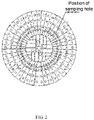
- FIG. 2 shows a schematic horizontal cross-sectional view of a structure of graphite block masonry in a reactor.
- the graphite block masonry has following parameters: an inner diameter of ⁇ 1.43 m, an outer diameter of ⁇ 2.63 m, a height of 3 m, and a graphite density of 2.4 g/cm 3 .
- a vertical through hole of ⁇ 55mm is arranged on the graphite block.
- each graphite block includes vertical round holes of ⁇ 55 mm and ⁇ 33 mm, but only the round hole of ⁇ 55 mm may be used for sampling.
- FIG. 3 shows a schematic diagram of a sampling position in a deep hole of a reactor graphite block.
- FIG. 4 shows a schematic diagram of a sampling position in a reactor graphite block.
- FIG. 3 and FIG. 4 show the position of the sampling hole.
- a sampling device of acquiring a graphite sample from a reactor graphite block may include a support, a lifter, and a sampling actuator.
- the support is placed on the reactor graphite block.
- a graphite sidewall sampling machine 10 is placed on a reactor graphite block 11.
- the lifter may be, for example but not limitation, a lifting and rotating mechanism for sampling 3 shown in FIG. 5 .
- the lifter may be inserted into the reactor graphite block in a first direction.
- the sampling actuator is arranged at an end of the lifter and is used to acquire a graphite sample from the reactor graphite block.
- the sampling actuator may be inserted into the reactor graphite block in a second direction, and the first direction is substantially perpendicular to the second direction.
- the first direction is a direction in which the graphite sidewall sampling machine 10 rises and falls in the reactor graphite block 11
- the second direction is a direction in which the sampling actuator feeds in the reactor graphite block 11.
- a caster is installed at a bottom of the support to move the support on the reactor graphite block, so that the lifter is aligned with a sampling position of the reactor graphite block.
- the sampling position is a vertical through hole of the reactor graphite block, and the lifter is movable up and down in the vertical through hole of the reactor graphite block in the first direction.
- the support may further include: a lifting fixed holder 2 fixed on an upper part of the support 1; a guide rail arranged on the lifting fixed holder 2, and the lifter being movable on the guide rail in the first direction; and a locking device used to lock the lifter on the guide rail.
- the lifter may include: a lifting rod that may be, by way of example but not limitation, a sampling operation rod 4 shown in FIG. 5 .
- the lifting rod may be inserted into the reactor graphite block in the first direction from the sampling position of the reactor graphite block.
- the lifting rod is a telescopic rod including a plurality of segments that are extendable and retractable in the first direction.
- Each of the plurality of segments may include: a mandrel arranged at a center of the telescopic rod; and a sleeve arranged around the mandrel on a periphery of the mandrel.
- the mandrel is extendable and retractable in the first direction to reach a desired length of the telescopic rod.
- the mandrel may be driven hydraulically or electrically.
- the sampling actuator 5 is installed at a bottom of the lifting rod, and a sampling operation wheel 6, for example, a manual sampling operation wheel 6, is installed at a top of the lifting rod and is used to actuate the sampling actuator.
- a sampling operation wheel 6 for example, a manual sampling operation wheel 6, is installed at a top of the lifting rod and is used to actuate the sampling actuator.
- the sampling operation wheel may also be driven electrically.
- a turn counter is installed on an upper part of the sampling operation wheel so as to record a feeding depth of the sampling actuator.
- the lifter may include a clamping mechanism and a rotating mechanism.
- the clamping mechanism is used to clamp the telescopic rod.
- the clamping mechanism may include a clamping wheel, a clamping mechanism reducer and a clamping mechanism servo motor.
- the rotating mechanism is used to drive, by rotation, the telescopic rod to move in the first direction.
- the rotating mechanism may include a gear, a rotating mechanism reducer and a rotating mechanism servo motor.
- the sampling actuator may include: a connecting sleeve 5-1 for connecting the sampling actuator 5 to the lifter; a transmission shaft 5-4 arranged in the connecting sleeve 5-1 and used to transmit a rotating power; and a rotary drill 5-11 that may rotate and travel in the second direction so as to cut graphite around the graphite sample 12.
- At least one cutting blade for example but not limitation, a sampling knife 5-12 shown in FIG. 7 , is arranged on an outer circumference of the rotary drill 5-11.
- the transmission shaft may transmit rotating power so that the rotary drill moves between a feeding state and a cutting state.
- the rotary drill rotates forward, and a cutting cam 5-14 follows the rotary drill and rotates in close contact with the graphite sample.
- the rotary drill rotates reversely and applies a radial force toward the graphite sample so as to cut off the graphite sample from the reactor graphite block.
- a cutting cam 5-14 is provided at an end of the rotary drill and is used to cut off the graphite sample from the reactor graphite block.
- the cutting cam is fixed on the rotary drill through a fixing pin 5-15, and the cutting cam 5-14 may move reversely with the rotary drill with the fixing pin 5-15 as a center.
- the cutting cam 5-14 rotates, a linear distance between a bonding surface of the cutting cam with the graphite sample and the fixing pin increases, so that the cutting cam applies a radial force toward the graphite sample to cut off the graphite sample.
- the rotary drill 5-11 is a hollow structure with a hollow inner cavity, and the graphite sample 12 cut off falls into the inner cavity of the rotary drill 5-11.
- the cutting cam is provided with a tooth surface on a side close to the graphite sample.
- a dimension of the cutting cam is set to prevent the graphite sample from falling out of the inner cavity of the rotary drill.
- the sampling device 10 is a sampling device of remotely sampling in a reactor graphite deep hole, which may be, for example, a graphite sidewall sampling device 10 shown in FIG. 5 .
- the graphite sidewall sampling device 10 may include: a fixed support 1, a lifting fixed holder 2, a lifting and rotating mechanism for sampling 3, a sampling operation rod 4, a sampling actuator 5, a manual sampling operation wheel 6, an operation control panel 7, a safety fence 8 and a distribution box 9.
- a caster is installed at the bottom of the fixed support 1 to facilitate the movement of the sampling device 10 and the alignment with the sampling hole.
- the lifting fixed holder 2 is welded to the upper part of the fixed support 1.
- the lifting and rotating mechanism for sampling 3 is installed on the lifting fixed holder 2 through the guide rail and the locking device, and may move up and down along the guide rail.
- a sampling operation rod clamping mechanism and a rotating mechanism are installed on the lifting and rotating mechanism for sampling 3.
- the sampling operation rod clamping mechanism includes a clamping wheel, a reducer and a servo motor.
- the rotating mechanism includes a gear, a reducer, and a servo motor.
- the sampling operation rod 4 includes a plurality of segments of stainless steel tubes and mandrels.
- a sampling actuator 5 is installed at the bottom of the sampling operation rod 4, and a manual sampling operation wheel 6 is installed at the top of the sampling operation rod 4.
- a length of the sampling operation rod 4 is determined by a number of the segments.
- the sampling actuator 5 is used for the sampling operation on the sidewall of the graphite 11.
- the manual sampling operation wheel 6 is used to provide a driving force for the sampling on the sidewall of the graphite 11.
- a turn counter is installed on the upper part of the manual sampling operation wheel 6 to record a feeding depth of the sampling actuator 5.
- a button provided on the operation control panel 7 may be increased to control the lifting and rotating of the sampling operation rod 4.
- the safety fence 8 is formed by welding conventional steel pipes to prevent unrelated persons from approaching the operating position.
- the distribution box 9 is used to install a servo motor controller and other electrical components.
- the sampling actuator 5 is a key component of the device, and the overall design is shown in FIG. 7 . Main functions of various components of the actuator are described as follows.
- the connecting sleeve 5-1 is connected with the sampling operation rod 4 in FIG. 5 ;
- a upper fixed seat 5-2 and the connecting sleeve 5-1 are fixed by a bolt;
- a lower fixed seat 5-3 is also fixed to the upper fixed seat 5-2 with a bolt; the upper fixed seat 5-2 and the lower fixed seat 5-3 simultaneously fix the rotary sampling device.
- the transmission shaft 5-4 transmits the upper rotating power to the rotary drill 5-11, and is connected with a driving helical gear 5-6 through a bolt;
- a bearing 5-5 includes a pair of angular contact bearings to prevent the transmission shaft 5-4 from moving up and down;
- the driven helical gear 5-7 is a welded part formed by welding a spline sleeve and a helical gear and is used to transmit the power of the driving helical gear 5-6 to the screw 5-10;
- the screw 5-10 is fixed to the fixed support 5-13, and an outer circumference of the screw 5-10 is processed into a special pitch external thread;
- a bearing 5-8 and a bearing 5-9 fix the driven helical gear 5-7 in the radial direction;
- the outer circumference of the rotary drill 5-11 is processed with a spline matching with the spline sleeve, and the inner circumference is processed into an internal thread that matches the special external thread of the screw 5-10, and the top is
- a set of cutting cams are designed in the present disclosure, as shown in FIG. 8 to FIG. 9 .
- the rotary drill 5-11 rotates, and the cutting cam 5-14 follows the rotary drill 5-11 and rotates in close contact with the graphite sample 12. After a certain number of rotations, the cutting cam reaches the cutting state.
- the rotary drill 5-11 rotates reversely.
- the cutting cam 5-14 is provided with a specially designed tooth surface on a side of the cutting cam 5-14 closely attached to the graphite sample 12, and the cutting cam 5-14 follows the rotary drill 5-11 to move reversely with the fixing pin 5-15 as the center.
- FIG. 6 shows an operating state of the graphite sidewall sampling device after it is installed in place.
- the graphite sidewall sampling device 10 is moved to above the graphite 11.
- the graphite sidewall sampling device 10 is fixed when it is observed that the sampling actuator 5 is aligned with the sampling hole on the graphite.
- a sampling depth and a sampling direction are set on the operation control panel 7.
- a down button is pressed.
- the sampling actuator 5 reaches a specified depth, a manual operation is performed so that the manual sampling operation wheel 6 rotates for a specified number of turns, and then rotates reversely for the same number of turns.
- an up button on the operation control panel 7 is pressed.
- the graphite sample may be taken out.
- the graphite sidewall sampling device 10 is operated as follows.
- the connecting sleeve 5-1 is connected with the sampling operation rod 4; the transmission shaft 5-4 is rotated to transmit a power to the driving helical gear 5-6, the driving helical gear 5-6 transmits the power to the driven helical gear 5-7, and the driven helical gear 5-7 drives, through the spline, the rotary drill 5 to rotate, and at the same time, the rotary drill 5-11 moves axially through the screw 5-10 to realize the feeding of the rotary drill 5-11; the sampling knife 5-12 on the top of the rotary drill 5-11 cuts the graphite around the graphite sample 12, and when the transmission shaft 5-4 rotates for a certain number of turns, the rotary drill 5-11 reaches a maximum stroke and stops feeding; then, the rotary drill 5-11 starts to rotate reversely, and the rotary drill 5-11 starts to return.
- the cutting cam 5-14 installed on the top of the rotary drill 5-11 cuts off the graphite sample 12 under the action of the reverse force, and prevents the graphite sample 12 from falling out of the inner cavity of the rotary drill 5-11.
- the rotary drill 5-11 After the transmission shaft 5-4 rotates reversely for the same number of turns, the rotary drill 5-11 returns to an original position. The graphite sidewall sampling device 10 is lifted, and the graphite sample 12 may be taken out.
Landscapes
- Physics & Mathematics (AREA)
- Health & Medical Sciences (AREA)
- Life Sciences & Earth Sciences (AREA)
- Chemical & Material Sciences (AREA)
- Analytical Chemistry (AREA)
- Biochemistry (AREA)
- General Health & Medical Sciences (AREA)
- General Physics & Mathematics (AREA)
- Immunology (AREA)
- Pathology (AREA)
- Engineering & Computer Science (AREA)
- Plasma & Fusion (AREA)
- General Engineering & Computer Science (AREA)
- High Energy & Nuclear Physics (AREA)
- Sampling And Sample Adjustment (AREA)
Abstract
Description
- The present disclosure relates to a sampling device, and in particular to a sampling device of remotely sampling on a deep hole sidewall of a graphite block.
- When it is required to take a certain weight of graphite sample from an inner wall of a vertical through hole in a reactor graphite block, the sample may only be taken by a remote operation because the graphite block is radioactive due to a long-term operation of the reactor and it is not allowed to destroy the reactor structure before the reactor is dismantled. According to the reactor structure and sampling requirements, a set of remote sampling tools is designed to perform a task of sampling on a sidewall of a vertical deep hole of a graphite block.
- A brief overview of the present disclosure is given below in order to provide a basic understanding of certain aspects of the present disclosure. It should be understood that the overview is not an exhaustive overview of the present disclosure. It is not intended to determine a key or important part of the present disclosure, nor is it intended to limit the scope of the present disclosure. Its purpose is merely to present some concepts in a simplified form as a prelude to a more detailed description to be described later.
- In view of the above requirements, the present disclosure provides a sampling device of acquiring a graphite sample from a reactor graphite block, including: a support placed on the reactor graphite block; a lifter configured to be insertable into the reactor graphite block in a first direction; and a sampling actuator arranged at an end of the lifter and configured to acquire a graphite sample from the reactor graphite block, wherein the sampling actuator is configured to insert into the reactor graphite block in a second direction, and the first direction is substantially perpendicular to the second direction. The sampling device provided in the present disclosure may perform a task of sampling on a sidewall of a vertical deep hole of a graphite block.
- These and other advantages of the present disclosure will be more apparent through the following detailed description of the preferred embodiments of the present disclosure in conjunction with the accompanying drawings.
- In order to further illustrate the above and other advantages and features of the present disclosure, the specific embodiments of the present disclosure will be further described in detail below with reference to the accompanying drawings. The drawings together with the following detailed description are included in the specification and form a part of the specification. Elements with the same function and structure are denoted by the same reference numerals. It should be understood that these drawings are only used to describe typical examples of the present disclosure, and should not be regarded as limiting the scope of the present disclosure, and in the drawings:
-
FIG. 1 shows a schematic longitudinal cross-sectional view of a structure of graphite block masonry in a reactor according to some embodiments; -
FIG. 2 shows a schematic horizontal cross-sectional view of a structure of graphite block masonry in a reactor according to some embodiments; -
FIG. 3 shows a schematic diagram of a sampling position in a deep hole of a reactor graphite block according to some embodiments; -
FIG. 4 shows a schematic diagram of a sampling position in a reactor graphite block according to some embodiments; -
FIG. 5 shows an overall schematic diagram of a sampling device of sampling on a reactor graphite block deep hole sidewall according to some embodiments; -
FIG. 6 shows a schematic diagram of a state in which the sampling device of sampling on the reactor graphite block deep hole sidewall is in place and in operation according to some embodiments; -
FIG. 7 shows a schematic diagram of a drilling and sampling actuator of the sampling device of sampling on the reactor graphite block deep hole sidewall according to some embodiments; -
FIG. 8 shows a partial enlarged schematic diagram of the drilling and sampling actuator of the sampling device of sampling on the reactor graphite block deep hole sidewall according to some embodiments; and -
FIG. 9 shows a schematic diagram of an operating state of a cutting cam of the drilling and sampling actuator of the sampling device of sampling on the reactor graphite block deep hole sidewall according to some embodiments. -
- 1 Fixed support
- 2 Lifting fixed holder
- 3 Lifting and rotating mechanism for sampling
- 4 Sampling operation rod
- 5 Sampling actuator
- 6 Manual sampling operation wheel
- 7 Operation control panel
- 8 Safety fence
- 9 Distribution box
- 10 Graphite sidewall sampling machine
- 11 Graphite
- 12 Graphite sample
- 5-1 Connecting sleeve
- 5-2 Upper fixed seat
- 5-3 Lower fixed seat
- 5-4 Transmission shaft
- 5-5 Bearing
- 5-6 Driving helical gear
- 5-7 Driven helical gear
- 5-8 Bearing
- 5-9 Bearing
- 5-10 Screw
- 5-11 Rotary drill
- 5-12 Sampling knife
- 5-13 Fixed support
- 5-14 Cutting cam
- 5-15 Fixing pin
- Exemplary embodiments of the present disclosure will be described below in conjunction with the accompanying drawings. For the sake of clarity and conciseness, not all features of the actual implementations are described in the specification. However, it should be understood that it is necessary to make many implementation-specific determinations, for example, to comply with system and business-related restrictions, during a development of any such actual implementation in order to achieve developer's specific objectives. These restrictions may vary with different implementations. In addition, it should be understood that although the development work may be very complicated and time-consuming, such development work is only a routine task for those skilled in the art who benefit from the content of the present disclosure.
- Here, it should be further noted that, in order to avoid obscuring the present disclosure due to unnecessary details, only the device structure and/or processing steps closely related to the solution according to the present disclosure are shown in the drawings, and other details of little relevance to the present disclosure are omitted.
- Because the graphite is radioactive due to a long-term operation of the reactor and it is not allowed to destroy a structure of the reactor before the reactor is dismantled, sampling may only be performed through a remote operation. For example, a certain weight of graphite block sample may be acquired from an inner sidewall of a vertical through hole on the graphite block. A sampling point is far away from an operating position, for example, a position of a sampling hole is about 3.5 m away from an upper surface of the graphite block. For example, a certain weight of graphite block sample may be acquired by drilling from a designated position on an inner wall of a Φ55 mm deep hole in a vertical direction of the graphite block in the reactor. The graphite block sample is required to be complete and have a weight of no less than 3 g. For example, it is required that a temperature of a graphite surface during drilling does not exceed 50 °C.
- At present, there is no dedicated tool of sampling on a sidewall of a deep hole of the radioactive graphite block in the reactor. No mature tools or technologies in China can be directly used, and no published papers or patented technologies in foreign countries can be used for reference. Therefore, it is necessary to design a set of remote sampling tools according to the structure of the reactor and sampling requirements, so as to perform the task of sampling on the sidewall of the vertical deep hole of the graphite block.
- According to the present disclosure, the remote sampling on the sidewall of the deep hole of the graphite block may be successfully performed without destroying the structure of the reactor and the graphite. A graphite sample with a length of 10 mm and a diameter of 8 mm was taken out, which may meet requirements of subsequent experimental analysis. The above-mentioned specifications of the acquired sample are only examples, and do not constitute a limitation to the sampling device of the present disclosure. The sampling device provided according to the present disclosure may also be used to sample a graphite sample of other specifications.
- A ring structure formed by graphite masonry is arranged in the reactor.
FIG. 1 andFIG. 2 show schematic structural diagrams of the graphite block.FIG. 1 shows a schematic longitudinal cross-sectional view of a structure of graphite block masonry in a reactor.FIG. 2 shows a schematic horizontal cross-sectional view of a structure of graphite block masonry in a reactor. In some embodiments, the graphite block masonry has following parameters: an inner diameter of Φ1.43 m, an outer diameter of Φ2.63 m, a height of 3 m, and a graphite density of 2.4 g/cm3. - A vertical through hole of Φ55mm is arranged on the graphite block.
- An operating position is, for example, 3.5 m above the graphite block. Referring to
FIG. 3 andFIG. 4 , each graphite block includes vertical round holes of Φ55 mm and Φ33 mm, but only the round hole of Φ55 mm may be used for sampling.FIG. 3 shows a schematic diagram of a sampling position in a deep hole of a reactor graphite block.FIG. 4 shows a schematic diagram of a sampling position in a reactor graphite block.FIG. 3 andFIG. 4 show the position of the sampling hole. - Sampling requirements are as follows.
- (1) The diameter of the graphite hole is only 55mm, and the space is narrow.
- (2) After drilling a hole in a sidewall of the graphite hole, the graphite sample is cut off and taken out by a sampling actuator.
- (3) The graphite temperature may not exceed 50 °C during sampling.
- According to some embodiments of the present disclosure, a sampling device of acquiring a graphite sample from a reactor graphite block is provided. The sampling device may include a support, a lifter, and a sampling actuator. The support is placed on the reactor graphite block. Referring to
FIG. 6 , for example, a graphitesidewall sampling machine 10 is placed on areactor graphite block 11. The lifter may be, for example but not limitation, a lifting and rotating mechanism for sampling 3 shown inFIG. 5 . The lifter may be inserted into the reactor graphite block in a first direction. The sampling actuator is arranged at an end of the lifter and is used to acquire a graphite sample from the reactor graphite block. The sampling actuator may be inserted into the reactor graphite block in a second direction, and the first direction is substantially perpendicular to the second direction. Referring toFIG. 6 , the first direction is a direction in which the graphitesidewall sampling machine 10 rises and falls in thereactor graphite block 11, and the second direction is a direction in which the sampling actuator feeds in thereactor graphite block 11. - A caster is installed at a bottom of the support to move the support on the reactor graphite block, so that the lifter is aligned with a sampling position of the reactor graphite block.
- The sampling position is a vertical through hole of the reactor graphite block, and the lifter is movable up and down in the vertical through hole of the reactor graphite block in the first direction.
- According to some embodiments of the present disclosure, the support may further include: a lifting fixed
holder 2 fixed on an upper part of the support 1; a guide rail arranged on the lifting fixedholder 2, and the lifter being movable on the guide rail in the first direction; and a locking device used to lock the lifter on the guide rail. - According to some embodiments of the present disclosure, the lifter may include: a lifting rod that may be, by way of example but not limitation, a sampling operation rod 4 shown in
FIG. 5 . - The lifting rod may be inserted into the reactor graphite block in the first direction from the sampling position of the reactor graphite block.
- According to some embodiments of the present disclosure, the lifting rod is a telescopic rod including a plurality of segments that are extendable and retractable in the first direction. Each of the plurality of segments may include: a mandrel arranged at a center of the telescopic rod; and a sleeve arranged around the mandrel on a periphery of the mandrel. The mandrel is extendable and retractable in the first direction to reach a desired length of the telescopic rod. Those skilled in the art may know that the mandrel may be driven hydraulically or electrically.
- According to some embodiments of the present disclosure, the
sampling actuator 5 is installed at a bottom of the lifting rod, and asampling operation wheel 6, for example, a manualsampling operation wheel 6, is installed at a top of the lifting rod and is used to actuate the sampling actuator. Those skilled in the art may know that the sampling operation wheel may also be driven electrically. - According to some embodiments of the present disclosure, a turn counter is installed on an upper part of the sampling operation wheel so as to record a feeding depth of the sampling actuator.
- According to some embodiments of the present disclosure, the lifter may include a clamping mechanism and a rotating mechanism. The clamping mechanism is used to clamp the telescopic rod. By way of example but not limitation, the clamping mechanism may include a clamping wheel, a clamping mechanism reducer and a clamping mechanism servo motor. The rotating mechanism is used to drive, by rotation, the telescopic rod to move in the first direction. By way of example but not limitation, the rotating mechanism may include a gear, a rotating mechanism reducer and a rotating mechanism servo motor.
- According to some embodiments of the present disclosure, the sampling actuator may include: a connecting sleeve 5-1 for connecting the
sampling actuator 5 to the lifter; a transmission shaft 5-4 arranged in the connecting sleeve 5-1 and used to transmit a rotating power; and a rotary drill 5-11 that may rotate and travel in the second direction so as to cut graphite around thegraphite sample 12. - According to some embodiments of the present disclosure, at least one cutting blade, for example but not limitation, a sampling knife 5-12 shown in
FIG. 7 , is arranged on an outer circumference of the rotary drill 5-11. - According to some embodiments of the present disclosure, the transmission shaft may transmit rotating power so that the rotary drill moves between a feeding state and a cutting state. In the feeding state, the rotary drill rotates forward, and a cutting cam 5-14 follows the rotary drill and rotates in close contact with the graphite sample. In the cutting state, the rotary drill rotates reversely and applies a radial force toward the graphite sample so as to cut off the graphite sample from the reactor graphite block.
- According to some embodiments of the present disclosure, a cutting cam 5-14 is provided at an end of the rotary drill and is used to cut off the graphite sample from the reactor graphite block. The cutting cam is fixed on the rotary drill through a fixing pin 5-15, and the cutting cam 5-14 may move reversely with the rotary drill with the fixing pin 5-15 as a center. As the cutting cam 5-14 rotates, a linear distance between a bonding surface of the cutting cam with the graphite sample and the fixing pin increases, so that the cutting cam applies a radial force toward the graphite sample to cut off the graphite sample.
- According to some embodiments of the present disclosure, the rotary drill 5-11 is a hollow structure with a hollow inner cavity, and the
graphite sample 12 cut off falls into the inner cavity of the rotary drill 5-11. - According to some embodiments of the present disclosure, the cutting cam is provided with a tooth surface on a side close to the graphite sample. A dimension of the cutting cam is set to prevent the graphite sample from falling out of the inner cavity of the rotary drill.
- According to some embodiments of the present disclosure, the
sampling device 10 is a sampling device of remotely sampling in a reactor graphite deep hole, which may be, for example, a graphitesidewall sampling device 10 shown inFIG. 5 . The graphitesidewall sampling device 10 may include: a fixed support 1, a lifting fixedholder 2, a lifting and rotating mechanism forsampling 3, a sampling operation rod 4, asampling actuator 5, a manualsampling operation wheel 6, an operation control panel 7, asafety fence 8 and a distribution box 9. - According to some embodiments of the present disclosure, a caster is installed at the bottom of the fixed support 1 to facilitate the movement of the
sampling device 10 and the alignment with the sampling hole. The lifting fixedholder 2 is welded to the upper part of the fixed support 1. The lifting and rotating mechanism for sampling 3 is installed on the lifting fixedholder 2 through the guide rail and the locking device, and may move up and down along the guide rail. A sampling operation rod clamping mechanism and a rotating mechanism are installed on the lifting and rotating mechanism forsampling 3. The sampling operation rod clamping mechanism includes a clamping wheel, a reducer and a servo motor. The rotating mechanism includes a gear, a reducer, and a servo motor. The sampling operation rod 4 includes a plurality of segments of stainless steel tubes and mandrels. Asampling actuator 5 is installed at the bottom of the sampling operation rod 4, and a manualsampling operation wheel 6 is installed at the top of the sampling operation rod 4. A length of the sampling operation rod 4 is determined by a number of the segments. Thesampling actuator 5 is used for the sampling operation on the sidewall of thegraphite 11. The manualsampling operation wheel 6 is used to provide a driving force for the sampling on the sidewall of thegraphite 11. A turn counter is installed on the upper part of the manualsampling operation wheel 6 to record a feeding depth of thesampling actuator 5. A button provided on the operation control panel 7 may be increased to control the lifting and rotating of the sampling operation rod 4. Thesafety fence 8 is formed by welding conventional steel pipes to prevent unrelated persons from approaching the operating position. The distribution box 9 is used to install a servo motor controller and other electrical components. - The
sampling actuator 5 is a key component of the device, and the overall design is shown inFIG. 7 . Main functions of various components of the actuator are described as follows. The connecting sleeve 5-1 is connected with the sampling operation rod 4 inFIG. 5 ; a upper fixed seat 5-2 and the connecting sleeve 5-1 are fixed by a bolt; a lower fixed seat 5-3 is also fixed to the upper fixed seat 5-2 with a bolt; the upper fixed seat 5-2 and the lower fixed seat 5-3 simultaneously fix the rotary sampling device. The transmission shaft 5-4 transmits the upper rotating power to the rotary drill 5-11, and is connected with a driving helical gear 5-6 through a bolt; a bearing 5-5 includes a pair of angular contact bearings to prevent the transmission shaft 5-4 from moving up and down; the driven helical gear 5-7 is a welded part formed by welding a spline sleeve and a helical gear and is used to transmit the power of the driving helical gear 5-6 to the screw 5-10; the screw 5-10 is fixed to the fixed support 5-13, and an outer circumference of the screw 5-10 is processed into a special pitch external thread; a bearing 5-8 and a bearing 5-9 fix the driven helical gear 5-7 in the radial direction; the outer circumference of the rotary drill 5-11 is processed with a spline matching with the spline sleeve, and the inner circumference is processed into an internal thread that matches the special external thread of the screw 5-10, and the top is welded with the sampling knife 5-12; the sampling knife 5-12 is used to cut the graphite around the graphite sample 12; the specially designed cutting cam 5-14 may cut off the graphite sample 12 when the rotary drill 5-11 reversely rotates to return, and prevent the graphite sample 12 from falling out of the inner cavity of the rotary drill 5-11; the fixing pin 5-15 is used to fix the cutting cam 5-14. - In order to solve the technical problem of cutting off the
graphite sample 12, a set of cutting cams are designed in the present disclosure, as shown inFIG. 8 to FIG. 9 . When the cutting cam is in the feeding state, the rotary drill 5-11 rotates, and the cutting cam 5-14 follows the rotary drill 5-11 and rotates in close contact with thegraphite sample 12. After a certain number of rotations, the cutting cam reaches the cutting state. When the cutting cam is in the cutting state, the rotary drill 5-11 rotates reversely. The cutting cam 5-14 is provided with a specially designed tooth surface on a side of the cutting cam 5-14 closely attached to thegraphite sample 12, and the cutting cam 5-14 follows the rotary drill 5-11 to move reversely with the fixing pin 5-15 as the center. As the cutting cam 5-14 rotates, a linear distance between the bonding surface of the cutting cam 5-14 with thegraphite sample 12 and the fixing pin 5-15 increases, and the cutting cam 5-14 applies a radial force toward thegraphite sample 12. When the radial force is large enough, thegraphite sample 12 is cut off and falls into the inner cavity of the rotary drill 5-11. Then, the sampling process ends. - According to some embodiments of the present disclosure, the operation process of the graphite
sidewall sampling device 10 is described in detail.FIG. 6 shows an operating state of the graphite sidewall sampling device after it is installed in place. - Firstly, the graphite
sidewall sampling device 10 is moved to above thegraphite 11. The graphitesidewall sampling device 10 is fixed when it is observed that thesampling actuator 5 is aligned with the sampling hole on the graphite. A sampling depth and a sampling direction are set on the operation control panel 7. A down button is pressed. When thesampling actuator 5 reaches a specified depth, a manual operation is performed so that the manualsampling operation wheel 6 rotates for a specified number of turns, and then rotates reversely for the same number of turns. Then, an up button on the operation control panel 7 is pressed. When thesampling actuator 5 is raised to a specified height, the graphite sample may be taken out. During sampling, the graphitesidewall sampling device 10 is operated as follows. The connecting sleeve 5-1 is connected with the sampling operation rod 4; the transmission shaft 5-4 is rotated to transmit a power to the driving helical gear 5-6, the driving helical gear 5-6 transmits the power to the driven helical gear 5-7, and the driven helical gear 5-7 drives, through the spline, therotary drill 5 to rotate, and at the same time, the rotary drill 5-11 moves axially through the screw 5-10 to realize the feeding of the rotary drill 5-11; the sampling knife 5-12 on the top of the rotary drill 5-11 cuts the graphite around thegraphite sample 12, and when the transmission shaft 5-4 rotates for a certain number of turns, the rotary drill 5-11 reaches a maximum stroke and stops feeding; then, the rotary drill 5-11 starts to rotate reversely, and the rotary drill 5-11 starts to return. At this time, the cutting cam 5-14 installed on the top of the rotary drill 5-11 cuts off thegraphite sample 12 under the action of the reverse force, and prevents thegraphite sample 12 from falling out of the inner cavity of the rotary drill 5-11. After the transmission shaft 5-4 rotates reversely for the same number of turns, the rotary drill 5-11 returns to an original position. The graphitesidewall sampling device 10 is lifted, and thegraphite sample 12 may be taken out. - Finally, it should be noted that the terms "comprise", "include" or any other variants thereof are intended to cover non-exclusive inclusion, so that a process, method, product or apparatus including a series of elements not only includes those elements, but also includes other elements not clearly listed, or further includes elements inherent to this process, method, product or apparatus. Moreover, if there are no more restrictions, the element defined by the sentence "including a..." does not exclude the existence of other identical elements in the process, method, product or apparatus that includes the element.
- Although the embodiments of the present disclosure have been described in detail above in conjunction with the accompanying drawings, it should be understood that the embodiments described above are only used to illustrate the present disclosure, and do not constitute a limitation to the present disclosure. For those skilled in the art, various modifications and changes may be made to the above embodiments without departing from the essence and scope of the present disclosure. Therefore, the scope of the present disclosure is limited only by the appended claims and their equivalent meanings.
Claims (35)
- A sampling device of acquiring a graphite sample from a reactor graphite block, comprising:a support placed on the reactor graphite block;a lifter configured to be insertable into the reactor graphite block in a first direction; anda sampling actuator arranged at an end of the lifter and configured to acquire a graphite sample from the reactor graphite block,wherein the sampling actuator is configured to insert into the reactor graphite block in a second direction, and the first direction is substantially perpendicular to the second direction.
- The sampling device according to claim 1, wherein a caster is installed at a bottom of the support to move the support on the reactor graphite block, so that the lifter is aligned with a sampling position of the reactor graphite block.
- The sampling device according to claim 2, wherein the sampling position is a vertical through hole of the reactor graphite block, and the lifter is configured to be movable up and down in the vertical through hole of the reactor graphite block in the first direction.
- The sampling device according to claim 1, wherein the support further comprises:a lifting fixed holder fixed on an upper part of the support;a guide rail arranged on the lifting fixed holder, wherein the lifter is configured to be movable on the guide rail in the first direction; anda locking device configured to lock the lifter on the guide rail.
- The sampling device according to claim 1, wherein the lifter comprises:
a lifting rod configured to insert into the reactor graphite block in the first direction from a sampling position of the reactor graphite block. - The sampling device according to claim 5, wherein the lifting rod is a telescopic rod comprising a plurality of segments that are extendable and retractable in the first direction.
- The sampling device according to claim 6, wherein each of the plurality of segments comprises:a mandrel arranged at a center of the telescopic rod; anda sleeve arranged around the mandrel on a periphery of the mandrel,wherein the mandrel is configured to extend and retract in the first direction to reach a desired length of the telescopic rod.
- The sampling device according to claim 5, wherein the sampling actuator is installed at a bottom of the lifting rod, and a sampling operation wheel is installed at a top of the lifting rod to actuate the sampling actuator.
- The sampling device according to claim 8, wherein a turn counter is installed on an upper part of the sampling operation wheel so as to record a feeding depth of the sampling actuator.
- The sampling device according to claim 1, wherein the lifter comprises:a clamping mechanism configured to clamp the telescopic rod; anda rotating mechanism configured to drive, by rotation, the telescopic rod to move in the first direction.
- The sampling device according to claim 10, wherein the clamping mechanism comprises a clamping wheel, a clamping mechanism reducer and a clamping mechanism servo motor; and the rotating mechanism comprises a gear, a rotating mechanism reducer and a rotating mechanism servo motor.
- The sampling device according to claim 1, wherein the sampling actuator comprises:a connecting sleeve configured to connect the sampling actuator to the lifter;a transmission shaft arranged in the connecting sleeve and configured to transmit a rotating power; anda rotary drill configured to be rotatable and to travel in the second direction.
- The sampling device according to claim 12, wherein the rotary drill is configured to cut off graphite around the graphite sample.
- The sampling device according to claim 12, wherein at least one cutting blade is arranged on an outer circumference of the rotary drill.
- The sampling device according to claim 12, wherein the transmission shaft is configured to transmit the rotating power so that the rotary drill moves between a feeding state and a cutting state, and at the feeding state, the rotary drill rotates forward, and at the cutting state, the rotary drill rotates reversely and applies a radial force toward the graphite sample, so as to cut off the graphite sample from the reactor graphite block.
- The sampling device according to claim 15, wherein a cutting cam is provided at an end of the rotary drill, the cutting cam is fixed on the rotary drill by a fixing pin and is configured to cut off the graphite sample from the reactor graphite block.
- The sampling device according to claim 16, wherein,in response to the rotary drill rotating forward, the cutting cam follows the rotary drill and rotates in close contact with the graphite sample;in response to the rotary drill rotating reversely, the cutting cam moves reversely with the rotary drill with the fixing pin as a center; anda linear distance between a bonding surface of the cutting cam with the graphite sample and the fixing pin increases with rotation of the cutting cam, so that the cutting cam applies a radial force toward the graphite sample to cut off the graphite sample.
- The sampling device according to claim 17, wherein the rotary drill is a hollow structure with a hollow inner cavity, and the cut-off graphite sample falls into the inner cavity of the rotary drill.
- The sampling device according to claim 17, wherein the cutting cam is provided with a tooth surface on a side of the cutting cam in close contact with the graphite sample.
- The sampling device according to claim 19, wherein a dimension of the cutting cam is set to prevent the graphite sample from falling out of the inner cavity of the rotary drill.
- A sampling device of acquiring a sample from a measurement object, comprising:a support placed on the measurement object;a lifter configured to be insertable into the measurement object in a first direction; anda sampling actuator arranged at an end of the lifter,wherein the sampling actuator is configured to insert into the measurement object in a second direction, and the first direction is substantially perpendicular to the second direction.
- The sampling device according to claim 21, wherein the measurement object is a graphite sample.
- The sampling device according to claim 21, wherein the measurement object is in a radioactive environment.
- An apparatus of measuring a graphite radioactivity, comprising:the sampling device according to claims 1 to 23, wherein the sampling device is configured to acquire a sample from graphite;a sample delivery device configured to deliver the sample acquired by the sampling device to a sample preparation device; andthe sample preparation device configured to receive and process the sample from the sample delivery device.
- The apparatus of measuring the graphite radioactivity according to claim 24, comprising:
an analysis and detection unit, wherein the sampling device is arranged in the analysis and detection unit. - The apparatus of measuring the graphite radioactivity according to claim 24, wherein the sampling device comprises:a support placed on a graphite to be sampled;a lifter configured to be insertable into the graphite in a first direction; anda sampling actuator arranged at an end of the lifter, wherein the sampling actuator is configured to insert into the graphite in a second direction, and the first direction is substantially perpendicular to the second direction.
- The apparatus of measuring the graphite radioactivity according to claim 26, wherein the sampling actuator is movable between a feeding state and a cutting state, and at the feeding state, the sampling actuator rotates forward , at the cutting state, the sampling actuator rotates reversely and applies a radial force toward the sample, so as to cut off the sample from the graphite.
- The apparatus of measuring the graphite radioactivity according to claim 27, wherein,a cutting cam is provided at an end of the sampling actuator,in response to the sampling actuator rotating forward, the cutting cam follows the rotary drill and rotates in close contact with the sample;in response to the sampling actuator rotating reversely, the cutting cam moves reversely with the rotary drill; andwith rotation of the cutting cam, the cutting cam applies a radial force toward the sample so as to cut off the sample from the graphite.
- The apparatus of measuring the graphite radioactivity according to any one of claims 26 to 28, wherein the sampling actuator comprises a hollow inner cavity, and the cut-off sample falls into the inner cavity.
- A sampling method of acquiring a sample from a graphite, comprising:moving a sampling device above the graphite;fixing the sampling device in response to observing that the sampling device is aligned with a sampling hole on the graphite;inserting a lifter of the sampling device into the sampling hole in a first direction until the sampling device reaches a depth; andinserting a sampling actuator arranged at an end of the lifter into the graphite in a second direction, wherein the first direction is substantially perpendicular to the second direction.
- The method according to claim 30, further comprising:
moving the sampling actuator between a feeding state and a cutting state, wherein at the feeding state, the sampling actuator rotates forward, and at the cutting state, the sampling actuator rotates reversely and applies a radial force toward the sample, so as to cut off the sample from the graphite. - The sampling method according to claim 31, wherein,a cutting cam is provided at an end of the sampling actuator;in response to the sampling actuator rotating forward, the cutting cam follows the sampling actuator and rotates in close contact with the graphite sample;in response to the sampling actuator rotating reversely, the cutting cam moves reversely with the sampling actuator; andwith rotation of the cutting cam, the cutting cam applies a radial force toward the sample so as to cut off the sample from the graphite.
- The sampling method according to claim 31 or 32, wherein the sampling actuator comprises a hollow inner cavity, and the cut-off sample falls into the inner cavity of the sampling actuator.
- The sampling method according to claim 33, further comprising:
rotating the sampling actuator so that the sampling actuator retracts into the lifter of the sampling device. - The sampling method according to claim 34, further comprising:
lifting the lifter of the sampling device above the graphite so as to take out the sample.
Applications Claiming Priority (2)
| Application Number | Priority Date | Filing Date | Title |
|---|---|---|---|
| CN202011609836.3A CN112557092B (en) | 2020-12-29 | 2020-12-29 | Sampling device |
| PCT/CN2021/098807 WO2022142140A1 (en) | 2020-12-29 | 2021-06-08 | Graphite radioactivity measurement device, sampling apparatus, and sampling method |
Publications (3)
| Publication Number | Publication Date |
|---|---|
| EP4043857A1 true EP4043857A1 (en) | 2022-08-17 |
| EP4043857A4 EP4043857A4 (en) | 2023-01-25 |
| EP4043857B1 EP4043857B1 (en) | 2023-08-09 |
Family
ID=75034614
Family Applications (1)
| Application Number | Title | Priority Date | Filing Date |
|---|---|---|---|
| EP21759225.2A Active EP4043857B1 (en) | 2020-12-29 | 2021-06-08 | Graphite radioactivity measurement device, sampling apparatus, and sampling method |
Country Status (4)
| Country | Link |
|---|---|
| US (1) | US12405188B2 (en) |
| EP (1) | EP4043857B1 (en) |
| CN (1) | CN112557092B (en) |
| WO (1) | WO2022142140A1 (en) |
Cited By (2)
| Publication number | Priority date | Publication date | Assignee | Title |
|---|---|---|---|---|
| CN112151200A (en) * | 2020-08-20 | 2020-12-29 | 中国原子能科学研究院 | Remote sampling system of radioactive graphite deep hole |
| RU2858983C1 (en) * | 2025-11-10 | 2026-03-25 | Федеральное государственное автономное образовательное учреждение высшего образования "Национальный исследовательский Томский политехнический университет" | Device for sampling from graphite blocks |
Families Citing this family (3)
| Publication number | Priority date | Publication date | Assignee | Title |
|---|---|---|---|---|
| CN112557092B (en) | 2020-12-29 | 2022-08-09 | 中国原子能科学研究院 | Sampling device |
| CN116213009B (en) * | 2023-03-04 | 2025-09-19 | 湖南大学 | Method for dismantling waste graphite blocks for retired graphite reactor |
| CN116907915B (en) * | 2023-09-14 | 2023-12-12 | 广东禹航环境科技有限公司 | Soil sampling equipment for soil pollution treatment |
Family Cites Families (26)
| Publication number | Priority date | Publication date | Assignee | Title |
|---|---|---|---|---|
| FR1508238A (en) * | 1966-11-21 | 1968-01-05 | Commissariat Energie Atomique | Remote working device in a tube |
| AR016883A1 (en) * | 1997-08-28 | 2001-08-01 | Shell Int Research | A ROTARY TREPANE TO DRILL |
| DE19811699A1 (en) * | 1998-03-10 | 1999-09-16 | Martin Honold | Sub soil gas sampling probe of modular construction |
| JP4081452B2 (en) | 2004-02-24 | 2008-04-23 | 独立行政法人海洋研究開発機構 | Crust core sample collection method |
| US8171808B2 (en) * | 2008-05-02 | 2012-05-08 | Johnson Industries, Inc. | Material sampling device with rotatable tube assembly |
| RU2378510C1 (en) * | 2008-07-01 | 2010-01-10 | Открытое акционерное общество "Сибирский химический комбинат" (ОАО "СХК") | Device for horizontal cutting of cores from well walls or channels |
| US20140131165A1 (en) * | 2012-11-14 | 2014-05-15 | Johnson Industries, Inc. | Material sampling device with integrated material analyzer assembly |
| CN204789019U (en) | 2015-06-12 | 2015-11-18 | 中钢集团邢台机械轧辊有限公司 | Dark blind hole plug cut off blade |
| RU2618214C1 (en) * | 2016-04-27 | 2017-05-03 | Акционерное общество Опытно-демонстрационный центр вывода из эксплуатации уран-графитовых ядерных реакторов | Device for local drilling of reactor setting graphite column tracts |
| CN205614855U (en) * | 2016-05-18 | 2016-10-05 | 大同新成新材料股份有限公司 | Drilling equipment of graphite product sample |
| CN106246124A (en) * | 2016-07-29 | 2016-12-21 | 中国石油天然气股份有限公司 | Downhole detection system and method thereof |
| CN107829699A (en) * | 2017-10-26 | 2018-03-23 | 西南石油大学 | A kind of anti-lost rock sampler of grinding type and application method |
| CN108119081A (en) * | 2018-02-28 | 2018-06-05 | 山东科技大学 | A kind of New Rock samples dedicated water drill bit |
| CN209040753U (en) | 2018-08-23 | 2019-06-28 | 中交隧道工程局有限公司 | A kind of cutter barrel brill having truncation tooth |
| CN209148339U (en) * | 2018-11-30 | 2019-07-23 | 重庆工程职业技术学院 | Geological soil collection device |
| CN109752209A (en) * | 2018-12-30 | 2019-05-14 | 孙浩宁 | Soil sampling device |
| CN209432492U (en) * | 2019-01-09 | 2019-09-24 | 郑州汇之丰科技有限公司 | A kind of convenient soil sampling drilling machine of sampling |
| CN110398389A (en) | 2019-06-18 | 2019-11-01 | 毕海民 | A kind of geotechnical engineering investigation ground sampler |
| JP6618135B1 (en) * | 2019-07-11 | 2019-12-11 | 千葉エンジニアリング株式会社 | sampler |
| CN211085716U (en) * | 2019-07-25 | 2020-07-24 | 徐州天艺制盖有限公司 | Drilling equipment convenient to petroleum geology sample detection |
| CN211477679U (en) * | 2019-12-19 | 2020-09-11 | 广东天人不动产测绘规划有限公司 | Sampling device for geological survey and drawing |
| CN111351681B (en) * | 2020-03-16 | 2023-01-06 | 东华理工大学 | A mechanical device for sampling rock and soil for civil engineering |
| CN211825141U (en) * | 2020-03-25 | 2020-10-30 | 刘志军 | Geotechnical engineering exploration quick sampling device |
| CN111350500A (en) * | 2020-04-14 | 2020-06-30 | 孟丽杰 | Soil sample collector for geological exploration |
| US11948700B2 (en) * | 2020-11-11 | 2024-04-02 | Grant Charters | In-situ method of drilling to collect dry samples from a nuclear reactor core interior for analysis |
| CN112557092B (en) | 2020-12-29 | 2022-08-09 | 中国原子能科学研究院 | Sampling device |
-
2020
- 2020-12-29 CN CN202011609836.3A patent/CN112557092B/en active Active
-
2021
- 2021-06-08 EP EP21759225.2A patent/EP4043857B1/en active Active
- 2021-06-08 US US17/436,458 patent/US12405188B2/en active Active
- 2021-06-08 WO PCT/CN2021/098807 patent/WO2022142140A1/en not_active Ceased
Cited By (3)
| Publication number | Priority date | Publication date | Assignee | Title |
|---|---|---|---|---|
| CN112151200A (en) * | 2020-08-20 | 2020-12-29 | 中国原子能科学研究院 | Remote sampling system of radioactive graphite deep hole |
| CN112151200B (en) * | 2020-08-20 | 2023-01-10 | 中国原子能科学研究院 | Remote sampling system of radioactive graphite deep hole |
| RU2858983C1 (en) * | 2025-11-10 | 2026-03-25 | Федеральное государственное автономное образовательное учреждение высшего образования "Национальный исследовательский Томский политехнический университет" | Device for sampling from graphite blocks |
Also Published As
| Publication number | Publication date |
|---|---|
| CN112557092B (en) | 2022-08-09 |
| WO2022142140A1 (en) | 2022-07-07 |
| EP4043857B1 (en) | 2023-08-09 |
| EP4043857A4 (en) | 2023-01-25 |
| CN112557092A (en) | 2021-03-26 |
| US12405188B2 (en) | 2025-09-02 |
| US20250044195A1 (en) | 2025-02-06 |
Similar Documents
| Publication | Publication Date | Title |
|---|---|---|
| US12405188B2 (en) | Apparatus of measuring graphite radioactivity, sampling device, and sampling method | |
| CN109163927B (en) | Soil sampler containing polychlorinated biphenyl | |
| CN217483910U (en) | Drilling bored concrete pile is with device that fetches earth | |
| CN116698497B (en) | Sampling device for highway pavement detection and method for using same | |
| CN115575165B (en) | Geological prospecting rock core sampling device | |
| US20020133928A1 (en) | Method and apparatus for removing pressure tubes from nuclear reactors | |
| CN117030336B (en) | Sample sampling unmanned aerial vehicle in depth of soil remediation land | |
| CN115184073A (en) | Rock core sampling device for geotechnical engineering | |
| CN117823068B (en) | Geological survey operation probing sampling device | |
| CN111360314B (en) | A cutting device | |
| US9121236B2 (en) | Storage, handling and positioning device for drill rods and methods thereof | |
| CN208937355U (en) | Rock core splits core machine | |
| US5931235A (en) | Cutter head, boring jig and device and process for sea bottom boring | |
| CN115014849A (en) | Core sampling device for engineering geological investigation | |
| CN220378232U (en) | Closed loop linkage control type underground electric cutting tool | |
| CN222579648U (en) | A sampling device for soil measurement | |
| CN116124507A (en) | Multi-shaft drill frame for drilling concrete test block core sample | |
| CN111795844A (en) | Sampler for civil engineering road surface quality detection | |
| CN110763507A (en) | A time-delayed sampling device for in situ detection of the efficacy of soil remediation agents | |
| US4764064A (en) | Tool changer | |
| WO2014105050A1 (en) | Storage, handling and positioning device for drill rods and methods thereof | |
| CN210317276U (en) | Rotating base for petroleum logging instrument | |
| RU2750374C1 (en) | Graphite sampling device in channel-type reactors | |
| CN222904529U (en) | A core cutting machine | |
| CN113740134A (en) | Be used for triaxial test soil sample preparation facilities |
Legal Events
| Date | Code | Title | Description |
|---|---|---|---|
| STAA | Information on the status of an ep patent application or granted ep patent |
Free format text: STATUS: UNKNOWN |
|
| STAA | Information on the status of an ep patent application or granted ep patent |
Free format text: STATUS: THE INTERNATIONAL PUBLICATION HAS BEEN MADE |
|
| PUAI | Public reference made under article 153(3) epc to a published international application that has entered the european phase |
Free format text: ORIGINAL CODE: 0009012 |
|
| STAA | Information on the status of an ep patent application or granted ep patent |
Free format text: STATUS: REQUEST FOR EXAMINATION WAS MADE |
|
| 17P | Request for examination filed |
Effective date: 20210903 |
|
| AK | Designated contracting states |
Kind code of ref document: A1 Designated state(s): AL AT BE BG CH CY CZ DE DK EE ES FI FR GB GR HR HU IE IS IT LI LT LU LV MC MK MT NL NO PL PT RO RS SE SI SK SM TR |
|
| A4 | Supplementary search report drawn up and despatched |
Effective date: 20230103 |
|
| RIC1 | Information provided on ipc code assigned before grant |
Ipc: G21C 17/00 20060101ALI20221221BHEP Ipc: G01N 1/08 20060101AFI20221221BHEP |
|
| GRAP | Despatch of communication of intention to grant a patent |
Free format text: ORIGINAL CODE: EPIDOSNIGR1 |
|
| STAA | Information on the status of an ep patent application or granted ep patent |
Free format text: STATUS: GRANT OF PATENT IS INTENDED |
|
| DAV | Request for validation of the european patent (deleted) | ||
| DAX | Request for extension of the european patent (deleted) | ||
| INTG | Intention to grant announced |
Effective date: 20230317 |
|
| GRAS | Grant fee paid |
Free format text: ORIGINAL CODE: EPIDOSNIGR3 |
|
| GRAA | (expected) grant |
Free format text: ORIGINAL CODE: 0009210 |
|
| STAA | Information on the status of an ep patent application or granted ep patent |
Free format text: STATUS: THE PATENT HAS BEEN GRANTED |
|
| AK | Designated contracting states |
Kind code of ref document: B1 Designated state(s): AL AT BE BG CH CY CZ DE DK EE ES FI FR GB GR HR HU IE IS IT LI LT LU LV MC MK MT NL NO PL PT RO RS SE SI SK SM TR |
|
| REG | Reference to a national code |
Ref country code: GB Ref legal event code: FG4D |
|
| REG | Reference to a national code |
Ref country code: CH Ref legal event code: EP |
|
| REG | Reference to a national code |
Ref country code: IE Ref legal event code: FG4D |
|
| REG | Reference to a national code |
Ref country code: DE Ref legal event code: R096 Ref document number: 602021004188 Country of ref document: DE |
|
| REG | Reference to a national code |
Ref country code: LT Ref legal event code: MG9D |
|
| REG | Reference to a national code |
Ref country code: NL Ref legal event code: MP Effective date: 20230809 |
|
| REG | Reference to a national code |
Ref country code: AT Ref legal event code: MK05 Ref document number: 1598048 Country of ref document: AT Kind code of ref document: T Effective date: 20230809 |
|
| PG25 | Lapsed in a contracting state [announced via postgrant information from national office to epo] |
Ref country code: GR Free format text: LAPSE BECAUSE OF FAILURE TO SUBMIT A TRANSLATION OF THE DESCRIPTION OR TO PAY THE FEE WITHIN THE PRESCRIBED TIME-LIMIT Effective date: 20231110 |
|
| PG25 | Lapsed in a contracting state [announced via postgrant information from national office to epo] |
Ref country code: IS Free format text: LAPSE BECAUSE OF FAILURE TO SUBMIT A TRANSLATION OF THE DESCRIPTION OR TO PAY THE FEE WITHIN THE PRESCRIBED TIME-LIMIT Effective date: 20231209 |
|
| PG25 | Lapsed in a contracting state [announced via postgrant information from national office to epo] |
Ref country code: SE Free format text: LAPSE BECAUSE OF FAILURE TO SUBMIT A TRANSLATION OF THE DESCRIPTION OR TO PAY THE FEE WITHIN THE PRESCRIBED TIME-LIMIT Effective date: 20230809 Ref country code: RS Free format text: LAPSE BECAUSE OF FAILURE TO SUBMIT A TRANSLATION OF THE DESCRIPTION OR TO PAY THE FEE WITHIN THE PRESCRIBED TIME-LIMIT Effective date: 20230809 Ref country code: PT Free format text: LAPSE BECAUSE OF FAILURE TO SUBMIT A TRANSLATION OF THE DESCRIPTION OR TO PAY THE FEE WITHIN THE PRESCRIBED TIME-LIMIT Effective date: 20231211 Ref country code: NO Free format text: LAPSE BECAUSE OF FAILURE TO SUBMIT A TRANSLATION OF THE DESCRIPTION OR TO PAY THE FEE WITHIN THE PRESCRIBED TIME-LIMIT Effective date: 20231109 Ref country code: NL Free format text: LAPSE BECAUSE OF FAILURE TO SUBMIT A TRANSLATION OF THE DESCRIPTION OR TO PAY THE FEE WITHIN THE PRESCRIBED TIME-LIMIT Effective date: 20230809 Ref country code: LV Free format text: LAPSE BECAUSE OF FAILURE TO SUBMIT A TRANSLATION OF THE DESCRIPTION OR TO PAY THE FEE WITHIN THE PRESCRIBED TIME-LIMIT Effective date: 20230809 Ref country code: LT Free format text: LAPSE BECAUSE OF FAILURE TO SUBMIT A TRANSLATION OF THE DESCRIPTION OR TO PAY THE FEE WITHIN THE PRESCRIBED TIME-LIMIT Effective date: 20230809 Ref country code: IS Free format text: LAPSE BECAUSE OF FAILURE TO SUBMIT A TRANSLATION OF THE DESCRIPTION OR TO PAY THE FEE WITHIN THE PRESCRIBED TIME-LIMIT Effective date: 20231209 Ref country code: HR Free format text: LAPSE BECAUSE OF FAILURE TO SUBMIT A TRANSLATION OF THE DESCRIPTION OR TO PAY THE FEE WITHIN THE PRESCRIBED TIME-LIMIT Effective date: 20230809 Ref country code: GR Free format text: LAPSE BECAUSE OF FAILURE TO SUBMIT A TRANSLATION OF THE DESCRIPTION OR TO PAY THE FEE WITHIN THE PRESCRIBED TIME-LIMIT Effective date: 20231110 Ref country code: FI Free format text: LAPSE BECAUSE OF FAILURE TO SUBMIT A TRANSLATION OF THE DESCRIPTION OR TO PAY THE FEE WITHIN THE PRESCRIBED TIME-LIMIT Effective date: 20230809 Ref country code: AT Free format text: LAPSE BECAUSE OF FAILURE TO SUBMIT A TRANSLATION OF THE DESCRIPTION OR TO PAY THE FEE WITHIN THE PRESCRIBED TIME-LIMIT Effective date: 20230809 |
|
| PG25 | Lapsed in a contracting state [announced via postgrant information from national office to epo] |
Ref country code: PL Free format text: LAPSE BECAUSE OF FAILURE TO SUBMIT A TRANSLATION OF THE DESCRIPTION OR TO PAY THE FEE WITHIN THE PRESCRIBED TIME-LIMIT Effective date: 20230809 |
|
| PG25 | Lapsed in a contracting state [announced via postgrant information from national office to epo] |
Ref country code: ES Free format text: LAPSE BECAUSE OF FAILURE TO SUBMIT A TRANSLATION OF THE DESCRIPTION OR TO PAY THE FEE WITHIN THE PRESCRIBED TIME-LIMIT Effective date: 20230809 |
|
| PG25 | Lapsed in a contracting state [announced via postgrant information from national office to epo] |
Ref country code: SM Free format text: LAPSE BECAUSE OF FAILURE TO SUBMIT A TRANSLATION OF THE DESCRIPTION OR TO PAY THE FEE WITHIN THE PRESCRIBED TIME-LIMIT Effective date: 20230809 Ref country code: RO Free format text: LAPSE BECAUSE OF FAILURE TO SUBMIT A TRANSLATION OF THE DESCRIPTION OR TO PAY THE FEE WITHIN THE PRESCRIBED TIME-LIMIT Effective date: 20230809 Ref country code: ES Free format text: LAPSE BECAUSE OF FAILURE TO SUBMIT A TRANSLATION OF THE DESCRIPTION OR TO PAY THE FEE WITHIN THE PRESCRIBED TIME-LIMIT Effective date: 20230809 Ref country code: EE Free format text: LAPSE BECAUSE OF FAILURE TO SUBMIT A TRANSLATION OF THE DESCRIPTION OR TO PAY THE FEE WITHIN THE PRESCRIBED TIME-LIMIT Effective date: 20230809 Ref country code: DK Free format text: LAPSE BECAUSE OF FAILURE TO SUBMIT A TRANSLATION OF THE DESCRIPTION OR TO PAY THE FEE WITHIN THE PRESCRIBED TIME-LIMIT Effective date: 20230809 Ref country code: CZ Free format text: LAPSE BECAUSE OF FAILURE TO SUBMIT A TRANSLATION OF THE DESCRIPTION OR TO PAY THE FEE WITHIN THE PRESCRIBED TIME-LIMIT Effective date: 20230809 Ref country code: SK Free format text: LAPSE BECAUSE OF FAILURE TO SUBMIT A TRANSLATION OF THE DESCRIPTION OR TO PAY THE FEE WITHIN THE PRESCRIBED TIME-LIMIT Effective date: 20230809 |
|
| REG | Reference to a national code |
Ref country code: DE Ref legal event code: R097 Ref document number: 602021004188 Country of ref document: DE |
|
| PG25 | Lapsed in a contracting state [announced via postgrant information from national office to epo] |
Ref country code: IT Free format text: LAPSE BECAUSE OF FAILURE TO SUBMIT A TRANSLATION OF THE DESCRIPTION OR TO PAY THE FEE WITHIN THE PRESCRIBED TIME-LIMIT Effective date: 20230809 |
|
| PLBE | No opposition filed within time limit |
Free format text: ORIGINAL CODE: 0009261 |
|
| STAA | Information on the status of an ep patent application or granted ep patent |
Free format text: STATUS: NO OPPOSITION FILED WITHIN TIME LIMIT |
|
| 26N | No opposition filed |
Effective date: 20240513 |
|
| PG25 | Lapsed in a contracting state [announced via postgrant information from national office to epo] |
Ref country code: SI Free format text: LAPSE BECAUSE OF FAILURE TO SUBMIT A TRANSLATION OF THE DESCRIPTION OR TO PAY THE FEE WITHIN THE PRESCRIBED TIME-LIMIT Effective date: 20230809 |
|
| PG25 | Lapsed in a contracting state [announced via postgrant information from national office to epo] |
Ref country code: BG Free format text: LAPSE BECAUSE OF FAILURE TO SUBMIT A TRANSLATION OF THE DESCRIPTION OR TO PAY THE FEE WITHIN THE PRESCRIBED TIME-LIMIT Effective date: 20230809 |
|
| PG25 | Lapsed in a contracting state [announced via postgrant information from national office to epo] |
Ref country code: BG Free format text: LAPSE BECAUSE OF FAILURE TO SUBMIT A TRANSLATION OF THE DESCRIPTION OR TO PAY THE FEE WITHIN THE PRESCRIBED TIME-LIMIT Effective date: 20230809 |
|
| PG25 | Lapsed in a contracting state [announced via postgrant information from national office to epo] |
Ref country code: MC Free format text: LAPSE BECAUSE OF FAILURE TO SUBMIT A TRANSLATION OF THE DESCRIPTION OR TO PAY THE FEE WITHIN THE PRESCRIBED TIME-LIMIT Effective date: 20230809 |
|
| REG | Reference to a national code |
Ref country code: CH Ref legal event code: PL |
|
| PG25 | Lapsed in a contracting state [announced via postgrant information from national office to epo] |
Ref country code: LU Free format text: LAPSE BECAUSE OF NON-PAYMENT OF DUE FEES Effective date: 20240608 |
|
| PG25 | Lapsed in a contracting state [announced via postgrant information from national office to epo] |
Ref country code: IE Free format text: LAPSE BECAUSE OF NON-PAYMENT OF DUE FEES Effective date: 20240608 |
|
| PG25 | Lapsed in a contracting state [announced via postgrant information from national office to epo] |
Ref country code: BE Free format text: LAPSE BECAUSE OF NON-PAYMENT OF DUE FEES Effective date: 20240630 Ref country code: CH Free format text: LAPSE BECAUSE OF NON-PAYMENT OF DUE FEES Effective date: 20240630 |
|
| REG | Reference to a national code |
Ref country code: BE Ref legal event code: MM Effective date: 20240630 |
|
| PGFP | Annual fee paid to national office [announced via postgrant information from national office to epo] |
Ref country code: DE Payment date: 20250630 Year of fee payment: 5 |
|
| PGFP | Annual fee paid to national office [announced via postgrant information from national office to epo] |
Ref country code: GB Payment date: 20250621 Year of fee payment: 5 |
|
| PGFP | Annual fee paid to national office [announced via postgrant information from national office to epo] |
Ref country code: FR Payment date: 20250617 Year of fee payment: 5 |
|
| PG25 | Lapsed in a contracting state [announced via postgrant information from national office to epo] |
Ref country code: CY Free format text: LAPSE BECAUSE OF FAILURE TO SUBMIT A TRANSLATION OF THE DESCRIPTION OR TO PAY THE FEE WITHIN THE PRESCRIBED TIME-LIMIT; INVALID AB INITIO Effective date: 20210608 |
|
| PG25 | Lapsed in a contracting state [announced via postgrant information from national office to epo] |
Ref country code: HU Free format text: LAPSE BECAUSE OF FAILURE TO SUBMIT A TRANSLATION OF THE DESCRIPTION OR TO PAY THE FEE WITHIN THE PRESCRIBED TIME-LIMIT; INVALID AB INITIO Effective date: 20210608 |