EP4043799A1 - Extractor hood for a hob and method for operating an extractor hood - Google Patents
Extractor hood for a hob and method for operating an extractor hood Download PDFInfo
- Publication number
- EP4043799A1 EP4043799A1 EP21157490.0A EP21157490A EP4043799A1 EP 4043799 A1 EP4043799 A1 EP 4043799A1 EP 21157490 A EP21157490 A EP 21157490A EP 4043799 A1 EP4043799 A1 EP 4043799A1
- Authority
- EP
- European Patent Office
- Prior art keywords
- hood
- extractor hood
- drive unit
- hob
- mode
- Prior art date
- Legal status (The legal status is an assumption and is not a legal conclusion. Google has not performed a legal analysis and makes no representation as to the accuracy of the status listed.)
- Granted
Links
Images

Classifications
-
- F—MECHANICAL ENGINEERING; LIGHTING; HEATING; WEAPONS; BLASTING
- F24—HEATING; RANGES; VENTILATING
- F24C—DOMESTIC STOVES OR RANGES ; DETAILS OF DOMESTIC STOVES OR RANGES, OF GENERAL APPLICATION
- F24C15/00—Details
- F24C15/20—Removing cooking fumes
- F24C15/2042—Devices for removing cooking fumes structurally associated with a cooking range e.g. downdraft
-
- F—MECHANICAL ENGINEERING; LIGHTING; HEATING; WEAPONS; BLASTING
- F24—HEATING; RANGES; VENTILATING
- F24C—DOMESTIC STOVES OR RANGES ; DETAILS OF DOMESTIC STOVES OR RANGES, OF GENERAL APPLICATION
- F24C15/00—Details
- F24C15/20—Removing cooking fumes
- F24C15/2021—Arrangement or mounting of control or safety systems
Definitions
- the present invention relates to an extractor hood for a hob, with at least one drive unit being variably adjustable for sucking a gaseous medium of a substance to be processed.
- the present invention relates further to a method for operating an extractor hood for a hob and an arrangement with an extractor hood and a hob.
- Extractor hoods are an integral part of modern kitchens and are used for extracting and filtering waste steam, i.e. vapors (cooking or baking vapors) produced during cooking or baking.
- Extractor hoods as separate components or elements or in combination with hob are known from the prior art.
- European patent application No. EP 2 975327 A1 describes hob with several cooking locations in combination with a hood being integrated in the hob. In the area around its geometric center, the hob has several recesses which are connected with one or more devices for removing cooking vapors through suction downwardly in a direction vertically below the hob.
- European patent application No. EP 3 290 813 A1 describes an extractor hood device with a ventilator and a housing which has a receiving space for the ventilator, and an air inlet opening and a filter.
- the hood device is characterized by a collecting vessel for liquids with at least one overflow opening.
- PCT patent applications No. WO 2017/029134 A1 and WO 2017/029128 A1 describes a combination appliance with a cooktop having at least one opening and an extractor hood being arranged below the cooktop for suctioning air from the space above the cooktop.
- German patent applications No. DE 10 2016 216 061 A1 describes a combination appliance with a hob and an extractor hood being integrated into the hob and comprising a filter unit whose fan is arranged below the hob.
- the extractor hood comprises a cover which is detachably connected to a part of the combination appliance and which comprises lamellae being arranged in the cover.
- German patent application No. DE 10 2017 109 435 A1 describes an operating device for operating a cooktop in order to adjust at least one cooking function.
- the operating device has a planar shaped adjusting device which is designed to be arranged in standby position in the area of the cooktop and to be moveable into at least one operating position which arranged at a distance from the cooktop.
- extractor hoods can either be activated or deactivated. Hobs can be operated in different power modes and these are available in stored settings. However, extractor hood settings are not changed or controlled, in particular in combination appliances comprising a hob and a hood. Further, there is no application of a pause function as deactivation of the hood in part for a specific period of time present on such a combination appliance. Current settings of an extractor hood are not memorized in order to be able to recover if the extractor hood went into a pause function and shall return into the previous condition after completion of the pause function.
- At least one of the objects is achieved by the extractor hood of independent claim 1, the method of claim 12 and/or the arrangement of claim 15. Further examples and applications of the invention result from the dependent claims and are explained in the following description with partial reference to the figures.
- a first general aspect of the invention relates to an extractor hood for a hob, with at least one drive unit, the at least one drive unit being variably adjustable for sucking a gaseous medium of a substance to be processed.
- the extractor hood is characterized in that the extractor hood, preferably the at least one drive unit, is configured to switch from a hood operating mode to a hood paused mode, preferably via at least one paused signal; and to remain in the hood paused mode for a predetermined time period, preferably via at least one automatic time control signal; and to reactivate the hood operating mode, preferably via at least one reactivation signal, wherein at least one setting for operating the hood operating mode is a recovered at least one setting.
- the invention provides, for example, an extractor hood as a suction device for the gaseous medium where at least one setting or preferably all necessary settings for operating the hood operating mode in a respective current state is/are stored and (chronologically) afterwards, i.e. after a switch of the hood operating mode to the hood paused mode to remain for a predetermined time period, can be recovered accordingly in order to switch from the hood paused mode back to the (previous) hood operating mode, i.e. to reactivate the hood operating mode.
- the storing of the at least one setting or preferably all settings for operating the hood operating mode can be for example either essentially continuously or intermittent or at least before switching from the hood operation mode to the hood paused mode.
- the hood paused mode may be preferably different to the hood operating mode.
- the hood paused mode may be an adjustable low power mode, preferably of the at least one drive unit driving a suction unit.
- the hood paused mode is different to the hood operating mode with regard to at least one (operating) setting.
- the low power mode may be a hood standby mode, i.e. a mode of minimum energy consumption of the extractor hood.
- the hood standby mode is a mode where the at least one drive unit is not switched off totally.
- the extractor hood may be configured for connection with a hob and/or the gaseous medium may be generated by at least one substance in a container such as food in a cooking vessel to be prepared by the hob.
- the gaseous medium can be a powdery medium, or a vaporous medium such as fumes.
- the at least one drive unit can be part of a blower unit or a suction unit.
- the at least one drive unit can be configured to switch from a current and/or an adjusted hood operating mode to the hood paused mode.
- the extractor hood may be preferably configured to be controlled, preferably in a closed loop configuration, electronically or digitally, for example via at least one digital signal.
- the predetermined time period for example may be generated by an automatic timed function.
- the recovered at least one setting may be at least one setting for operating the hood operating mode being stored - as described above - before switching to the hood paused mode.
- the recovered at least one setting may comprise a parameter or a set of parameters or a time sequence of parameters of the at least one drive unit in the hood operating mode, preferably at least a rotational speed of the at least one drive unit and/or of at least one propeller being connected to the at least one drive unit.
- the at least one propeller may be designed to generate the suction effect or the suction function of the extractor hood for the gaseous medium.
- the recovered at least one setting can comprise a quantity of the gaseous medium being measured per time or a flow rate of the gaseous medium.
- the quantity or the flow rate may be preferably parameters being measured by at least one sensor unit.
- the at least one drive unit may comprise or may be configured for connection with at least one propeller for generating a suction flow of the gaseous medium in a flow direction.
- the at least one drive unit can be connectable or can be connected to at least one propeller for generating a suction flow.
- the extractor hood may comprise or can be configured for connection with a control unit for adjusting at least two hood modes of the at least one drive unit, preferably for adjusting at least one time sequence of the at least two hood modes of the at least one drive unit.
- the control unit can preferably be an (electronic) computing device with known components and elements of internal hardware units such as at least one central processing unit (CPU) being configured to perform calculations and logic operations required to execute a computer program in order to control the at least one drive unit, at least one random access memory unit(RAM) for temporary storage of data and/or information, at least one input/output unit for signal communication, at least one energy supply unit, etc.
- CPU central processing unit
- RAM random access memory
- input/output unit for signal communication
- energy supply unit etc.
- the at least one drive unit of the extractor hood may comprise a control unit as disclosed herein.
- the extractor hood can comprise or may be configured for connection with at least one sensor unit for recording and/or generating at least one parameter of the at least one setting and/or at least one signal for controlling the at least one drive unit, preferably by a control unit.
- the at least one sensor unit can be configured to detect the presence of the gaseous medium and/or of the substance to be processed and/or of a user in front of the extractor hood.
- the extractor hood can act automatically, for example to switch from a hood operating mode to the hood paused mode if it is detected that the user is absence from the hob after a predetermined or predefined time duration. It is also possible that the extractor hood switches from a hood operating mode to the hood paused mode if it is detected that substance generating the gaseous medium is absence from the hob or that least on significant amount of gaseous medium is generated.
- the extractor hood may comprise or can be configured for connection with at least one memory unit for storing and/or restoring the at least one setting.
- the extractor hood may comprise at least one filter unit for at least partially filtering the gaseous medium and/or the extractor hood may comprise at least one grid structure, the at least one filter unit and/or the at least one grid structure can be arranged in a flow direction of the gaseous medium in a flow channel in front of at least one propeller being connected to the at least one drive unit.
- the extractor hood may be configured for signal communication with a hob, preferably a wireless signal communication, to cause the hob to switch from a hob operating mode to a hob paused mode, preferably via at least one paused signal; and to remain in the hob paused mode for a predetermined time period, preferably via at least one automatic time control signal; and to reactivate the hob operating mode, preferably via at least one reactivation signal.
- a hob preferably a wireless signal communication
- the extractor hood can be connectable or can be connected to a hob or can at last interact with a hob via a signal communication.
- the hob can be controlled at least partially via the extractor hood accordingly, preferably to switch from a hob operating mode to a hob paused mode and after a predetermined time period reactivate or return to the hob operating mode via at least one recovered signal.
- the signal communication comprises alternatively or additionally a wired communication.
- combo hob it is, for example, possible to provide a combination of an extractor hood according as disclosed herein together with a hob, known as "combo hob".
- the extractor hood can be integrated into the hob or can be positioned at a distance (preferably in close distance), i.e. is spaced apart from the hob.
- control unit controls both the hob and the extractor hood.
- a second general aspect of the invention relates to a method for operating an extractor hood for a hob, preferably an extractor hood as disclosed herein, with at least one drive unit, the at least one drive unit being variably adjustable for sucking a gaseous medium of a substance to be processed, the method comprising: Operating the at least one drive unit in a hood operating mode; Providing at least one paused signal; Switching of the at least one drive unit from the hood operating mode to a hood paused mode; Remaining in the hood paused mode for a predetermined time period; Providing at least one reactivation signal; Reactivating the hood operating mode; Operating the at least one drive unit in the hood operating mode with at least one setting being recovered.
- the method according to the invention can be preferably at least partially a computer-implemented method to perform at least the controlling of the at least one drive unit and/or the at least one propeller.
- remaining in the hood paused mode may further comprise providing at least one automatic time control signal for predetermining the time period.
- the method may further comprise storing the at least one setting before switching of the at least one drive unit from the hood operating mode to a hood paused mode.
- a third general aspect of the invention relates to an arrangement with a hob and an extractor hood as disclosed herein, wherein the extractor hood is integrated in the hob or the extractor hood is spaced apart from the hob.
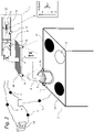
- Figure 1 illustrates schematically an example of an arrangement with a hob 2 and an example of an extractor hood 1 according to the invention.
- the hob 2 can be based on a cooking hob known from the prior art with known components and elements and comprises preferably at least one cooking zone 11.
- the at least one cooking zone 11 can comprise an induction plate and/or a gas burner and/or an electric hot plate or the like in order to process a substance 5 in a pot 12 being placed on the at least one cooking zone 11.
- the substance 5 such as food being in a cooking vessel 12 can be prepared by heat treatment (warming up).
- fumes 4 occur (cooking or baking fumes) resulting from the heat treatment (warming up) of the substance 5, i.e. of food 5.
- the fumes 4 can also contain odor-forming fats, for example.
- the arrangement further includes an extractor hood 1.
- the hob 2 has an integrated extractor hood 1 according to the invention.
- the extractor hood 1 is at least partially integrated in the hob 2.
- the extractor hood 1 can be preferably arranged between the at least one cooking zone 11 and a further at least one cocking zone 11, for example in order to optimize the sucking process of the fumes 4.
- the flow direction of the sucked fumes 4 is labeled with "X" in figure 1 .
- the extractor hood 1 or at least a part of the extractor hood 1 may be preferably configured to be controlled electronically or digitally by a control unit 7, preferably in a closed loop configuration, for example via a signal communication S.
- the control unit 7 is part of the extractor unit 1.
- the control unit 7 is part of the hob 2 or of a separate remote control device (not shown in the figures for the sake of clarity) for at least partially controlling the extractor hood 1 and/or the hob 2.
- the separate remote control device may comprise a display unit, e.g. a touchscreen, for corresponding interaction with a user of the extractor hood 1 and/or the hob 2.
- the control unit 7 can comprise an (electronic) computing device with known components and elements of internal hardware units such as at least one central processing unit (CPU) being configured to perform calculations and logic operations required to execute a computer program, at least one random access memory unit (RAM) for temporary storage of data and/or information, at least one input/output unit for signal communication, at least one energy supply unit, etc.
- CPU central processing unit
- RAM random access memory unit
- the computer program can comprise algorithms in order to at least partially control the extractor hood 1 and/or the hob 2 accordingly as it is further described exemplary in detail below.
- the signal communication S can be a wired and/or a wireless (e.g. WLAN, Bluetooth or the like of near field communication technology) signal communication S.
- a wireless e.g. WLAN, Bluetooth or the like of near field communication technology
- the extractor hood 1 may comprise or is at least configured for connection with a storage unit 14, for example via a signal communication S.
- the storage unit 14 is configured to store at least one setting SE or preferably all necessary settings SE for operating the extractor hood 1, for example in a predefined or predetermined or calculated hood operating mode.
- the hood operating mode represents a mode of the extractor hood 1 sucking gaseous medium being generated by the substance 5 and will be described in further detail below.
- the extractor hood 1 further comprises a drive unit 3.
- Figure 1 illustrates schematically a part of the inner region of the extractor hood 1 with the drive unit 3 in the highlighted section labeled with "Z".
- the drive unit 3 may comprise an electric motor (not shown in figure 1 for the sake of clarity).
- the drive unit 3 comprises or is configured for connection with a sucking unit in the form of a propeller 6 and drives the propeller 6. Following, the propeller 6 generates a suction flow of the gaseous medium 4, i.e. the fumes 4.
- the drive unit 3 together with the propeller 6 or at least the propeller 6 may be arranged in a flow channel 13 of the extractor hood 1 in order to achieve an optimal suction effect or optimal suction efficiency for the flow of fumes 4 from the hob 2.
- the drive unit 3 for driving the propeller 6 is configured and/or variably adjustable to operate the propeller 6 in different operating modes and thus hood operating modes for sucking the gaseous medium of fumes 4.
- the rotational speed [rpm] and/or the drive torque [Nm] of the drive unit 3 depending on the intensity and/or amount of the fumes 4 and thus the propeller 6 can be adjusted accordingly or can be adjusted at the drive unit 3.
- the flow channel 13 comprises inside the channel at least one sensor unit 8 being configured to detect at least the presence of fumes 4 in the flow channel 13 and/or preferably an average amount of fumes 4 being sucked by the propeller 6. In other words, with the at least one sensor unit 8 it is possible to measure a quantity of the gaseous medium of fumes 4 per time or a flow rate of the fumes 4.
- the extractor hood 1 comprises or is configured for connection with at least one sensor unit 8 outside the flow channel 13.
- Such at least one sensor unit 8 may detect and/or measure, for example, the presence of fumes 4 in order to automatically initiate or start the extractor hood 1, i.e. the propeller 6 of the drive unit 3, into a hood operating mode A of corresponding rotational speed of the drive unit 3 and/or the propeller 6 (see figure 1 ).
- the at least one signal unit 8 may record and/or generate at least one parameter of at least one setting SE for operating the extractor hood 1 and preferably the drive unit 3.
- the at least one sensor unit 8 outside the flow channel 13 and/or the at least one sensor unit 8 inside the flow channel 13 may additionally or alternatively be configured to record and/or generate at least one signal for controlling the at least one drive unit 3, preferably by the control unit 7.
- the at least one sensor unit 8 may comprise for example an optical sensor and/or an electro-mechanical sensor being configured to record and/or generate the at least one parameter of at least one setting SE for controlling the extractor hood 1 and preferably the drive unit 3 of the extractor hood 1.
- the at least one sensor unit 8 is at least in signal communication S with the drive unit 3, the control unit 7 and/or the storage unit 9 of the extractor hood 1.
- the flow channel 13 of the extractor hood 1 comprises a filter unit 9 for at least partially filtering the fumes 4.
- the filter unit 9 may be arranged upstream, i.e. in flow direction X in front of the propeller 6.
- the extractor hood 1 further comprises a grid structure 10.
- the grid structure 10 can be, for example, made from a metallic material, in order to prevent objects from accidentally entering the extractor hood 1. During suction 4, fumes 4 passes through the grid structure 10 on the way to the flow channel 13.
- the hob 2 and/or the extractor hood 1 may be operated separately from each other or in mutual interaction with each other.
- the extractor hood 1 and/or the hob 2 can be operated by a user via a display unit (not shown in figure 1 for the sake of clarity) being part of the hob 2 and/or the extractor hood 1, or via a separate remote control device comprising a display unit and being preferably in wireless signal communication S with the hob 2 and/or the extractor hood 1.
- the extractor hood 1 and preferably the drive unit 3 of the extractor hood 1 is configured to switch from a hood operating mode A of corresponding rotational speed [rpm] of the propeller 6 for example to a hood paused mode B of corresponding lower rotational speed [rpm] of the propeller 6 being different to the rotational speed [rpm] of the propeller 6 in the hood operating mode A.
- Switching between mode A and mode B can be preferably initialized and/or performed via at least one paused signal S which is further described in detail below.
- At least one setting SE or preferably all necessary settings SE for operating the hood operating mode A, preferably operating the drive unit 3, are stored in the storage unit 14, for example via the control unit 7.
- the hood paused mode may be an adjustable low power mode of the drive unit 3.
- the hood paused mode is different to the hood operating mode with regard to at least one (operating) setting SE.
- the at least one paused signal S may be generated, for example, by the control unit 7 and can, for example, result due to a user request. It can also be initiated and/or generated by at least one sensor unit 8 and thus automatically without the need of a user input.
- control unit 7 is configured to adjust at least two modes A, B of the extractor hood 1 and preferably the drive unit 3, preferably via a signal communication S with at least one paused signal S.
- the extractor hood 1 and preferably the drive unit 3 of the extractor hood 1 is further configured to remain in the hood paused mode B for a predetermined time period. Remaining can be preferably initialized and/or performed via at least one automatic time control signal S.
- the at least one automatic time control signal S may be generated, for example, by the control unit 7 and can result due to an automatic timed function being implemented as computer program and executed on the control unit 7.
- the extractor hood 1 and preferably the drive unit 3 of the extractor hood 1 is further configured to reactivate the hood operating mode A.
- the reactivation of the hood operating mode A can be preferably at least initiated and/or performed via at least one reactivation signal S, wherein at least one setting SE for operating the hood operating mode A, i.e. a setting SE which is necessary to operate the extractor hood 1 in the hood operating mode A, is a recovered at least one setting SE.
- Figure 2 illustrates schematically a further, i.e. second example of an arrangement with a hob 2 and an extractor hood 1 according to the invention.
- the extractor hood 1 is configured as a separate autarkic extractor hood 1 being spaced apart from the hob 2 with its respective cooking zones 11.
- the extractor hood 1 is in signal communication S with the hob 2, preferably via the control unit 7 of the extractor hood 1.
- the signal communication S can be a wired and/or a wireless signal communication S.
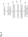
- Figure 3 illustrates a flowchart of an example of the method according to the invention.
- the method can be initiated or started in phase S10 by operating the extractor hood 1 in a hood operating mode A.
- Food 5 to be prepared is in a pot or a cooking vessel 12 on a cooking zone 11 of a hob 2 and fumes 4 are generated due to heat treatment of the food 5.
- the extractor hood 1 and preferably the drive unit 3 and/or the propeller 6 are in an operating mode with, for example, a certain rotational speed [rpm] of the drive unit 3 and/or the propeller 6 in order to suck the fumes 4.
- At least one paused signal S is provided which causes the extractor hood 1 and thus the drive unit 3 to switch from the hood operating mode A to the hood paused mode B.
- At least one setting SE or preferably all necessary settings SE for operating the extractor hood 1 and thus the drive unit 3 in the hood operating mode A is/are stored in phase S20 in the storage unit 14 of the extractor hood 1.
- the at least one setting SE or preferably all necessary settings SE comprise a parameter and/or a set of parameters and/or a time sequence of parameters of the extractor hood 1 and preferably of the drive unit 3 in the hood operating mode A.
- the parameter or the set of parameters can be a rotational speed [rpm] of the drive unit and/or a rotational speed [rpm] of a suction device being driven by the drive unit 3 such as the propeller 6 and/or a drive torque [Nm] of the drive unit 3 or the like.
- the at least one setting SE comprise at least one parameter that represents a characteristic value of the fumes 4 being recorded and/or generated by at least on sensor unit 8.
- phase S30 the extractor hood 1 switches from the hood operating mode A to the hood paused mode B.
- the hood paused mode B is different to the hood operating mode A with regard to at least one setting SE.
- the hood paused mode B is an adjustable low power mode, preferably of the at least one drive unit 3 driving a suction unit such as the propeller 6 of the extractor hood 1.
- the rotational speed [rpm] of the drive unit 3 and/or the propeller 6 is reduced to a predetermined lower level. This results further in a reduced noise level or noise emission of the extractor hood 1, i.e. the extractor hood 1 is in the hood paused mode B more quiet.
- the extractor hood 1 Once the extractor hood 1 has reached the hood paused mode B, it remains in the hood paused mode B for a predetermined time period in phase S40.
- the remaining in the hood paused mode B for a predetermined time period can be preferably realized via at least one automatic time control signal S.
- the predetermined time period for example may be generated by an automatic timed function.
- the automatic timed function is implemented as computer program and executed, for example, on the control unit 7.
- the hood paused mode B represents a hood standby mode of the extractor hood 1 with minimum energy consumption.
- At least one reactivation signal S is provided which causes the extractor hood 1 and thus the drive unit 3 to switch from the hood paused mode B to the hood operating mode A.
- the hood operating mode A of the extractor hood 1 is reactivated, i.e. the extractor hood 1 switches from the hood paused mode B to the hood operating mode A via and/or using at least one setting SE or preferably all necessary settings SE for operating the extractor hood 1 and thus the drive unit 3 in the hood operating mode A, wherein the at least one setting SE or preferably all necessary settings SE are recovered from the storing unit 14.
- phase S60 the extractor hood 1 and thus the drive unit 3 is operated in the hood operating mode A which represents the hood operating mode A before switching the extractor hood 1 in the hood paused mode B.
- the user needs not to adjust at least one setting SE of the extractor hood 1 again since it is recovered from the storage unit 14.
- the hood paused mode B can be applied accordingly to a hob 2 with at least one cooking zone 11 being in signal communication S with the extractor hood 1.
- the extractor hood 1 can be configured for signal communication S with the hob 2 to cause the hob 2 - when switching from the hood operating mode A to the hood operating mode B - to switch from a hob operating mode (corresponding to the hood operating mode A) to a hob paused mode (corresponding to the hood paused mode B) with reduced or minimized energy consumption of the hob 2.
- the method according to the invention can be preferably at least partially a computer-implemented method to perform at least the controlling of the at least one drive unit 3 and/or the at least one propeller 6 and/or the hob 2.
- the invention can be realized at least partially in hardware and/or software and can be transferred to or realized with several physical products, i.e. apparatuses and/or devices.
- the invention can be transferred to at least one computer program product as regards preferably the method or at least partially the method according to the invention.
- the invention also claims protection for the subject matter and the features of the sub-claims independently of the claims referred to.
Landscapes
- Engineering & Computer Science (AREA)
- Chemical & Material Sciences (AREA)
- Combustion & Propulsion (AREA)
- Mechanical Engineering (AREA)
- General Engineering & Computer Science (AREA)
- Ventilation (AREA)
- Prevention Of Fouling (AREA)
Abstract
Description
- The present invention relates to an extractor hood for a hob, with at least one drive unit being variably adjustable for sucking a gaseous medium of a substance to be processed. The present invention relates further to a method for operating an extractor hood for a hob and an arrangement with an extractor hood and a hob.
- Extractor hoods are an integral part of modern kitchens and are used for extracting and filtering waste steam, i.e. vapors (cooking or baking vapors) produced during cooking or baking.
- Extractor hoods as separate components or elements or in combination with hob are known from the prior art.
- European patent application No.
EP 2 975327 A1 - European patent application No.
EP 3 290 813 A1 -
PCT patent applications No. WO 2017/029134 A1 and
WO 2017/029128 A1 describes a combination appliance with a cooktop having at least one opening and an extractor hood being arranged below the cooktop for suctioning air from the space above the cooktop. - German patent applications No.
DE 10 2016 216 061 A1 describes a combination appliance with a hob and an extractor hood being integrated into the hob and comprising a filter unit whose fan is arranged below the hob. The extractor hood comprises a cover which is detachably connected to a part of the combination appliance and which comprises lamellae being arranged in the cover. - German patent application No.
DE 10 2017 109 435 A1 describes an operating device for operating a cooktop in order to adjust at least one cooking function. The operating device has a planar shaped adjusting device which is designed to be arranged in standby position in the area of the cooktop and to be moveable into at least one operating position which arranged at a distance from the cooktop. - As regards the extractor hoods known from prior art, they can either be activated or deactivated. Hobs can be operated in different power modes and these are available in stored settings. However, extractor hood settings are not changed or controlled, in particular in combination appliances comprising a hob and a hood. Further, there is no application of a pause function as deactivation of the hood in part for a specific period of time present on such a combination appliance. Current settings of an extractor hood are not memorized in order to be able to recover if the extractor hood went into a pause function and shall return into the previous condition after completion of the pause function.
- It is hence an object of the invention to provide an extractor hood for a hob with improved handling characteristics regarding the change of operating modes.
- It is a further object of the invention to provide a method for operating an extractor hood according to which handling characteristics regarding the change of operating modes are improved and it is a further object of the invention to provide an arrangement with a hob and an extractor hood according to the invention.
- At least one of the objects is achieved by the extractor hood of
independent claim 1, the method ofclaim 12 and/or the arrangement of claim 15. Further examples and applications of the invention result from the dependent claims and are explained in the following description with partial reference to the figures. - A first general aspect of the invention relates to an extractor hood for a hob, with at least one drive unit, the at least one drive unit being variably adjustable for sucking a gaseous medium of a substance to be processed. The extractor hood is characterized in that the extractor hood, preferably the at least one drive unit, is configured to switch from a hood operating mode to a hood paused mode, preferably via at least one paused signal; and to remain in the hood paused mode for a predetermined time period, preferably via at least one automatic time control signal; and to reactivate the hood operating mode, preferably via at least one reactivation signal, wherein at least one setting for operating the hood operating mode is a recovered at least one setting.
- The invention provides, for example, an extractor hood as a suction device for the gaseous medium where at least one setting or preferably all necessary settings for operating the hood operating mode in a respective current state is/are stored and (chronologically) afterwards, i.e. after a switch of the hood operating mode to the hood paused mode to remain for a predetermined time period, can be recovered accordingly in order to switch from the hood paused mode back to the (previous) hood operating mode, i.e. to reactivate the hood operating mode.
- The storing of the at least one setting or preferably all settings for operating the hood operating mode can be for example either essentially continuously or intermittent or at least before switching from the hood operation mode to the hood paused mode.
- The hood paused mode may be preferably different to the hood operating mode. The hood paused mode may be an adjustable low power mode, preferably of the at least one drive unit driving a suction unit. In other words, the hood paused mode is different to the hood operating mode with regard to at least one (operating) setting.
- It is also possible that the low power mode may be a hood standby mode, i.e. a mode of minimum energy consumption of the extractor hood. In other words, the hood standby mode is a mode where the at least one drive unit is not switched off totally.
- The extractor hood may be configured for connection with a hob and/or the gaseous medium may be generated by at least one substance in a container such as food in a cooking vessel to be prepared by the hob. The gaseous medium can be a powdery medium, or a vaporous medium such as fumes. The at least one drive unit can be part of a blower unit or a suction unit.
- The at least one drive unit can be configured to switch from a current and/or an adjusted hood operating mode to the hood paused mode.
- The extractor hood may be preferably configured to be controlled, preferably in a closed loop configuration, electronically or digitally, for example via at least one digital signal.
- The predetermined time period for example may be generated by an automatic timed function.
- According to a further aspect of the invention, the recovered at least one setting may be at least one setting for operating the hood operating mode being stored - as described above - before switching to the hood paused mode.
- This allows, for example, the exact reproduction or restoration of a specific state of the extractor hood before switching into the hood paused mode and after leaving the hood paused mode.
- According to a further aspect of the invention, the recovered at least one setting, preferably being used to reactivate the hood operating mode, may comprise a parameter or a set of parameters or a time sequence of parameters of the at least one drive unit in the hood operating mode, preferably at least a rotational speed of the at least one drive unit and/or of at least one propeller being connected to the at least one drive unit.
- This allows, for example, a comprehensive control of the at least one drive unit in a closed loop configuration. Further, it is for example possible to check the at least one drive unit for proper functioning.
- The at least one propeller may be designed to generate the suction effect or the suction function of the extractor hood for the gaseous medium.
- According to a further aspect of the invention, the recovered at least one setting can comprise a quantity of the gaseous medium being measured per time or a flow rate of the gaseous medium.
- The quantity or the flow rate may be preferably parameters being measured by at least one sensor unit.
- This allows, for example, an optimized adjustment and/or operation of the extractor hood and further the at least one drive unit on the basis of the medium to be sucked.
- According to a further aspect of the invention, the at least one drive unit may comprise or may be configured for connection with at least one propeller for generating a suction flow of the gaseous medium in a flow direction.
- In other words, the at least one drive unit can be connectable or can be connected to at least one propeller for generating a suction flow.
- According to a further aspect of the invention, the extractor hood may comprise or can be configured for connection with a control unit for adjusting at least two hood modes of the at least one drive unit, preferably for adjusting at least one time sequence of the at least two hood modes of the at least one drive unit.
- The control unit can preferably be an (electronic) computing device with known components and elements of internal hardware units such as at least one central processing unit (CPU) being configured to perform calculations and logic operations required to execute a computer program in order to control the at least one drive unit, at least one random access memory unit(RAM) for temporary storage of data and/or information, at least one input/output unit for signal communication, at least one energy supply unit, etc.
- Alternatively, it is possible that the at least one drive unit of the extractor hood may comprise a control unit as disclosed herein.
- According to a further aspect of the invention, the extractor hood can comprise or may be configured for connection with at least one sensor unit for recording and/or generating at least one parameter of the at least one setting and/or at least one signal for controlling the at least one drive unit, preferably by a control unit.
- This allows, for example, the provision of an extractor hood with an integrated closed loop control function which entails a completely separate or autarkic acting extractor hood, preferably being independent from a hob.
- According to a further aspect of the invention, the at least one sensor unit can be configured to detect the presence of the gaseous medium and/or of the substance to be processed and/or of a user in front of the extractor hood.
- This allows, for example, that the extractor hood can act automatically, for example to switch from a hood operating mode to the hood paused mode if it is detected that the user is absence from the hob after a predetermined or predefined time duration. It is also possible that the extractor hood switches from a hood operating mode to the hood paused mode if it is detected that substance generating the gaseous medium is absence from the hob or that least on significant amount of gaseous medium is generated.
- According to a further aspect of the invention, the extractor hood may comprise or can be configured for connection with at least one memory unit for storing and/or restoring the at least one setting.
- This allows, for example, a later reactivation of individual or respective stored operating modes and preferably the at least one drive unit. This means for example that the extractor hood needs no longer to be set manually by a user for example.
- According to a further aspect of the invention, the extractor hood may comprise at least one filter unit for at least partially filtering the gaseous medium and/or the extractor hood may comprise at least one grid structure, the at least one filter unit and/or the at least one grid structure can be arranged in a flow direction of the gaseous medium in a flow channel in front of at least one propeller being connected to the at least one drive unit.
- This avoids, for example, the suction of foreign objects, which can damage the at least one drive unit of the extractor hood.
- According to a further aspect of the invention, the extractor hood may be configured for signal communication with a hob, preferably a wireless signal communication, to cause the hob to switch from a hob operating mode to a hob paused mode, preferably via at least one paused signal; and to remain in the hob paused mode for a predetermined time period, preferably via at least one automatic time control signal; and to reactivate the hob operating mode, preferably via at least one reactivation signal.
- In other words, the extractor hood can be connectable or can be connected to a hob or can at last interact with a hob via a signal communication.
- This allows, for example, that the hob can be controlled at least partially via the extractor hood accordingly, preferably to switch from a hob operating mode to a hob paused mode and after a predetermined time period reactivate or return to the hob operating mode via at least one recovered signal.
- It is possible that the signal communication comprises alternatively or additionally a wired communication.
- It is, for example, possible to provide a combination of an extractor hood according as disclosed herein together with a hob, known as "combo hob". The extractor hood can be integrated into the hob or can be positioned at a distance (preferably in close distance), i.e. is spaced apart from the hob.
- It is possible that the control unit controls both the hob and the extractor hood.
- A second general aspect of the invention relates to a method for operating an extractor hood for a hob, preferably an extractor hood as disclosed herein, with at least one drive unit, the at least one drive unit being variably adjustable for sucking a gaseous medium of a substance to be processed, the method comprising:
Operating the at least one drive unit in a hood operating mode; Providing at least one paused signal; Switching of the at least one drive unit from the hood operating mode to a hood paused mode; Remaining in the hood paused mode for a predetermined time period; Providing at least one reactivation signal; Reactivating the hood operating mode; Operating the at least one drive unit in the hood operating mode with at least one setting being recovered. - It is possible that the method according to the invention can be preferably at least partially a computer-implemented method to perform at least the controlling of the at least one drive unit and/or the at least one propeller.
- According to a further aspect of the invention, remaining in the hood paused mode may further comprise providing at least one automatic time control signal for predetermining the time period.
- According to a further aspect of the invention, the method may further comprise storing the at least one setting before switching of the at least one drive unit from the hood operating mode to a hood paused mode.
- A third general aspect of the invention relates to an arrangement with a hob and an extractor hood as disclosed herein, wherein the extractor hood is integrated in the hob or the extractor hood is spaced apart from the hob.
- In order to avoid repetition, features which are purely directed to the method according to the invention and/or disclosed in connection therewith should also be considered as disclosed according to the extractor device and be claimable and vice versa.
- The previously described examples and features of the invention can be combined with each other in any way.
- Further or other details and advantageous effects of the invention are described in more detail below with reference to the attached figures:
- Fig. 1
- illustrates schematically an example of an arrangement with a hob and an extractor hood according to the invention;
- Fig. 2
- illustrates schematically a further example of an arrangement with a hob and an extractor hood according to the invention;
- Fig. 3
- illustrates a flowchart of an example of the method according to the invention.
- Identical or functionally equivalent components or elements are marked or labeled in the figures with the same reference signs. For their explanation, reference is also made to the description of other examples and/or figures in order to avoid repetition.
- The following detailed description of the examples shown in the figures serves as a closer illustration or exemplification and is in no way intended to limit the scope of the invention.
-
Figure 1 illustrates schematically an example of an arrangement with ahob 2 and an example of anextractor hood 1 according to the invention. - The
hob 2 can be based on a cooking hob known from the prior art with known components and elements and comprises preferably at least onecooking zone 11. - The at least one
cooking zone 11 can comprise an induction plate and/or a gas burner and/or an electric hot plate or the like in order to process asubstance 5 in apot 12 being placed on the at least onecooking zone 11. In other words, thesubstance 5 such as food being in acooking vessel 12 can be prepared by heat treatment (warming up). - In the context of food preparation, it is a physical phenomenon that so-called
fumes 4 occur (cooking or baking fumes) resulting from the heat treatment (warming up) of thesubstance 5, i.e. offood 5. - In addition to water vapor as the main component, the
fumes 4 can also contain odor-forming fats, for example. To suck and filter thefumes 4, the arrangement further includes anextractor hood 1. - The
hob 2 has an integratedextractor hood 1 according to the invention. In detail, theextractor hood 1 is at least partially integrated in thehob 2. Theextractor hood 1 can be preferably arranged between the at least onecooking zone 11 and a further at least one cockingzone 11, for example in order to optimize the sucking process of thefumes 4. The flow direction of the sucked fumes 4 is labeled with "X" infigure 1 . - The
extractor hood 1 or at least a part of theextractor hood 1 may be preferably configured to be controlled electronically or digitally by a control unit 7, preferably in a closed loop configuration, for example via a signal communication S. - The control unit 7 is part of the
extractor unit 1. Alternatively, it is possible that the control unit 7 is part of thehob 2 or of a separate remote control device (not shown in the figures for the sake of clarity) for at least partially controlling theextractor hood 1 and/or thehob 2. The separate remote control device may comprise a display unit, e.g. a touchscreen, for corresponding interaction with a user of theextractor hood 1 and/or thehob 2. - The control unit 7 can comprise an (electronic) computing device with known components and elements of internal hardware units such as at least one central processing unit (CPU) being configured to perform calculations and logic operations required to execute a computer program, at least one random access memory unit (RAM) for temporary storage of data and/or information, at least one input/output unit for signal communication, at least one energy supply unit, etc.
- The computer program can comprise algorithms in order to at least partially control the
extractor hood 1 and/or thehob 2 accordingly as it is further described exemplary in detail below. - The signal communication S can be a wired and/or a wireless (e.g. WLAN, Bluetooth or the like of near field communication technology) signal communication S.
- In addition, the
extractor hood 1 may comprise or is at least configured for connection with astorage unit 14, for example via a signal communication S. - The
storage unit 14 is configured to store at least one setting SE or preferably all necessary settings SE for operating theextractor hood 1, for example in a predefined or predetermined or calculated hood operating mode. The hood operating mode represents a mode of theextractor hood 1 sucking gaseous medium being generated by thesubstance 5 and will be described in further detail below. - The
extractor hood 1 further comprises adrive unit 3.Figure 1 illustrates schematically a part of the inner region of theextractor hood 1 with thedrive unit 3 in the highlighted section labeled with "Z". Thedrive unit 3 may comprise an electric motor (not shown infigure 1 for the sake of clarity). Thedrive unit 3 comprises or is configured for connection with a sucking unit in the form of apropeller 6 and drives thepropeller 6. Following, thepropeller 6 generates a suction flow of thegaseous medium 4, i.e. thefumes 4. Thedrive unit 3 together with thepropeller 6 or at least thepropeller 6 may be arranged in aflow channel 13 of theextractor hood 1 in order to achieve an optimal suction effect or optimal suction efficiency for the flow offumes 4 from thehob 2. - The
drive unit 3 for driving thepropeller 6 is configured and/or variably adjustable to operate thepropeller 6 in different operating modes and thus hood operating modes for sucking the gaseous medium offumes 4. Preferably, the rotational speed [rpm] and/or the drive torque [Nm] of thedrive unit 3 depending on the intensity and/or amount of thefumes 4 and thus thepropeller 6 can be adjusted accordingly or can be adjusted at thedrive unit 3. - The
flow channel 13 comprises inside the channel at least onesensor unit 8 being configured to detect at least the presence offumes 4 in theflow channel 13 and/or preferably an average amount offumes 4 being sucked by thepropeller 6. In other words, with the at least onesensor unit 8 it is possible to measure a quantity of the gaseous medium offumes 4 per time or a flow rate of thefumes 4. - Further, the
extractor hood 1 comprises or is configured for connection with at least onesensor unit 8 outside theflow channel 13. Such at least onesensor unit 8 may detect and/or measure, for example, the presence offumes 4 in order to automatically initiate or start theextractor hood 1, i.e. thepropeller 6 of thedrive unit 3, into a hood operating mode A of corresponding rotational speed of thedrive unit 3 and/or the propeller 6 (seefigure 1 ). After the detection and/or measurement, the at least onesignal unit 8 may record and/or generate at least one parameter of at least one setting SE for operating theextractor hood 1 and preferably thedrive unit 3. - The at least one
sensor unit 8 outside theflow channel 13 and/or the at least onesensor unit 8 inside theflow channel 13 may additionally or alternatively be configured to record and/or generate at least one signal for controlling the at least onedrive unit 3, preferably by the control unit 7. - The at least one
sensor unit 8 may comprise for example an optical sensor and/or an electro-mechanical sensor being configured to record and/or generate the at least one parameter of at least one setting SE for controlling theextractor hood 1 and preferably thedrive unit 3 of theextractor hood 1. - It is possible that the at least one
sensor unit 8 is at least in signal communication S with thedrive unit 3, the control unit 7 and/or thestorage unit 9 of theextractor hood 1. - In addition, the
flow channel 13 of theextractor hood 1 comprises afilter unit 9 for at least partially filtering thefumes 4. Thefilter unit 9 may be arranged upstream, i.e. in flow direction X in front of thepropeller 6. - The
extractor hood 1 further comprises agrid structure 10. Thegrid structure 10 can be, for example, made from a metallic material, in order to prevent objects from accidentally entering theextractor hood 1. Duringsuction 4, fumes 4 passes through thegrid structure 10 on the way to theflow channel 13. - The
hob 2 and/or theextractor hood 1 may be operated separately from each other or in mutual interaction with each other. For example, theextractor hood 1 and/or thehob 2 can be operated by a user via a display unit (not shown infigure 1 for the sake of clarity) being part of thehob 2 and/or theextractor hood 1, or via a separate remote control device comprising a display unit and being preferably in wireless signal communication S with thehob 2 and/or theextractor hood 1. - The
extractor hood 1 and preferably thedrive unit 3 of theextractor hood 1 is configured to switch from a hood operating mode A of corresponding rotational speed [rpm] of thepropeller 6 for example to a hood paused mode B of corresponding lower rotational speed [rpm] of thepropeller 6 being different to the rotational speed [rpm] of thepropeller 6 in the hood operating mode A. Switching between mode A and mode B can be preferably initialized and/or performed via at least one paused signal S which is further described in detail below. - Before the switching between mode A to mode B is performed, at least one setting SE or preferably all necessary settings SE for operating the hood operating mode A, preferably operating the
drive unit 3, are stored in thestorage unit 14, for example via the control unit 7. - The hood paused mode may be an adjustable low power mode of the
drive unit 3. In other words, the hood paused mode is different to the hood operating mode with regard to at least one (operating) setting SE. - The at least one paused signal S may be generated, for example, by the control unit 7 and can, for example, result due to a user request. It can also be initiated and/or generated by at least one
sensor unit 8 and thus automatically without the need of a user input. - In other words, the control unit 7 is configured to adjust at least two modes A, B of the
extractor hood 1 and preferably thedrive unit 3, preferably via a signal communication S with at least one paused signal S. - The
extractor hood 1 and preferably thedrive unit 3 of theextractor hood 1 is further configured to remain in the hood paused mode B for a predetermined time period. Remaining can be preferably initialized and/or performed via at least one automatic time control signal S. - The at least one automatic time control signal S may be generated, for example, by the control unit 7 and can result due to an automatic timed function being implemented as computer program and executed on the control unit 7.
- The
extractor hood 1 and preferably thedrive unit 3 of theextractor hood 1 is further configured to reactivate the hood operating mode A. The reactivation of the hood operating mode A can be preferably at least initiated and/or performed via at least one reactivation signal S, wherein at least one setting SE for operating the hood operating mode A, i.e. a setting SE which is necessary to operate theextractor hood 1 in the hood operating mode A, is a recovered at least one setting SE. -
Figure 2 illustrates schematically a further, i.e. second example of an arrangement with ahob 2 and anextractor hood 1 according to the invention. - The
extractor hood 1 is configured as a separateautarkic extractor hood 1 being spaced apart from thehob 2 with itsrespective cooking zones 11. - The
extractor hood 1 is in signal communication S with thehob 2, preferably via the control unit 7 of theextractor hood 1. The signal communication S can be a wired and/or a wireless signal communication S. - The description of components and elements in
figure 2 which are already illustrated inFigure 1 is omitted to avoid repetition. -
Figure 3 illustrates a flowchart of an example of the method according to the invention. - Focus is now put on an example of the method according to the invention. Components and elements for executing or performing the method being referred to step rather into the background as they are already described above on the basis of the illustrations in
figures 1 and2 . - For the sake of clarity, only main phases of the example of the method are illustrated in the flowchart in
figure 3 . - As regards the illustration in
figure 3 , the method can be initiated or started in phase S10 by operating theextractor hood 1 in a hood operatingmode A. Food 5 to be prepared is in a pot or acooking vessel 12 on acooking zone 11 of ahob 2 andfumes 4 are generated due to heat treatment of thefood 5. Theextractor hood 1 and preferably thedrive unit 3 and/or thepropeller 6 are in an operating mode with, for example, a certain rotational speed [rpm] of thedrive unit 3 and/or thepropeller 6 in order to suck thefumes 4. - Next, at least one paused signal S is provided which causes the
extractor hood 1 and thus thedrive unit 3 to switch from the hood operating mode A to the hood paused mode B. - Before the switching is initiated and/or completed, at least one setting SE or preferably all necessary settings SE for operating the
extractor hood 1 and thus thedrive unit 3 in the hood operating mode A is/are stored in phase S20 in thestorage unit 14 of theextractor hood 1. - The at least one setting SE or preferably all necessary settings SE comprise a parameter and/or a set of parameters and/or a time sequence of parameters of the
extractor hood 1 and preferably of thedrive unit 3 in the hood operating mode A. The parameter or the set of parameters can be a rotational speed [rpm] of the drive unit and/or a rotational speed [rpm] of a suction device being driven by thedrive unit 3 such as thepropeller 6 and/or a drive torque [Nm] of thedrive unit 3 or the like. - It is also possible that the at least one setting SE comprise at least one parameter that represents a characteristic value of the
fumes 4 being recorded and/or generated by at least onsensor unit 8. - In phase S30 the
extractor hood 1 switches from the hood operating mode A to the hood paused mode B. The hood paused mode B is different to the hood operating mode A with regard to at least one setting SE. - The hood paused mode B is an adjustable low power mode, preferably of the at least one
drive unit 3 driving a suction unit such as thepropeller 6 of theextractor hood 1. Preferably, the rotational speed [rpm] of thedrive unit 3 and/or thepropeller 6 is reduced to a predetermined lower level. This results further in a reduced noise level or noise emission of theextractor hood 1, i.e. theextractor hood 1 is in the hood paused mode B more quiet. - Once the
extractor hood 1 has reached the hood paused mode B, it remains in the hood paused mode B for a predetermined time period in phase S40. The remaining in the hood paused mode B for a predetermined time period can be preferably realized via at least one automatic time control signal S. The predetermined time period for example may be generated by an automatic timed function. The automatic timed function is implemented as computer program and executed, for example, on the control unit 7. - It is also possible that the hood paused mode B represents a hood standby mode of the
extractor hood 1 with minimum energy consumption. - Next, at least one reactivation signal S is provided which causes the
extractor hood 1 and thus thedrive unit 3 to switch from the hood paused mode B to the hood operating mode A. - In phase S50 the hood operating mode A of the
extractor hood 1 is reactivated, i.e. theextractor hood 1 switches from the hood paused mode B to the hood operating mode A via and/or using at least one setting SE or preferably all necessary settings SE for operating theextractor hood 1 and thus thedrive unit 3 in the hood operating mode A, wherein the at least one setting SE or preferably all necessary settings SE are recovered from the storingunit 14. - In phase S60, the
extractor hood 1 and thus thedrive unit 3 is operated in the hood operating mode A which represents the hood operating mode A before switching theextractor hood 1 in the hood paused mode B. - The user needs not to adjust at least one setting SE of the
extractor hood 1 again since it is recovered from thestorage unit 14. - Additionally, or alternatively, it is possible that the hood paused mode B can be applied accordingly to a
hob 2 with at least onecooking zone 11 being in signal communication S with theextractor hood 1. Theextractor hood 1 can be configured for signal communication S with thehob 2 to cause the hob 2 - when switching from the hood operating mode A to the hood operating mode B - to switch from a hob operating mode (corresponding to the hood operating mode A) to a hob paused mode (corresponding to the hood paused mode B) with reduced or minimized energy consumption of thehob 2. - It is possible that the method according to the invention can be preferably at least partially a computer-implemented method to perform at least the controlling of the at least one
drive unit 3 and/or the at least onepropeller 6 and/or thehob 2. - The invention is not limited to the example described above. Rather, a large number of variants and modifications are possible, which also make use of the inventive idea and therefore fall within the scope of protection.
- The invention can be realized at least partially in hardware and/or software and can be transferred to or realized with several physical products, i.e. apparatuses and/or devices.
- The invention can be transferred to at least one computer program product as regards preferably the method or at least partially the method according to the invention.
- Preferably, the invention also claims protection for the subject matter and the features of the sub-claims independently of the claims referred to.
-
- 1
- extractor hood
- 2
- hob
- 3
- drive unit
- 4
- gaseous medium/fumes
- 5
- substance/food
- 6
- propeller
- 7
- control unit
- 8
- sensor unit
- 9
- filter unit
- 10
- grid structure
- 11
- cooking zone
- 12
- pot/cooking vessel
- 13
- flow channel
- 14
- storage unit
- A
- hood operating mode
- B
- hood paused mode
- SE
- setting
- X
- flow direction
Claims (15)
- An extractor hood (1) for a hob (2), with at least one drive unit (3), the at least one drive unit (3) being variably adjustable for sucking a gaseous medium (4) of a substance (5) to be processed,
characterized in that
the at least one drive unit (3) is configured to• switch from a hood operating mode (A) to a hood paused mode (B), preferably via at least one paused signal (S); and• to remain in the hood paused mode (B) for a predetermined time period, preferably via at least one automatic time control signal (S); and• to reactivate the hood operating mode (A), preferably via at least one reactivation signal (S), wherein at least one setting (SE) for operating the hood operating mode (A) is a recovered at least one setting (SE). - The extractor hood (1) according to claim 1,
wherein the recovered at least one setting (SE) is at least one setting (SE) for operating the hood operating mode (A) being stored before switching to the hood paused mode (B). - The extractor hood (1) according to claim 1 or 2,
wherein the recovered at least one setting (SE) comprises a parameter or a set of parameters or a time sequence of parameters of the at least one drive unit (3) in the hood operating mode (A), preferably at least a rotational speed (RS) of the at least one drive unit (3) and/or of at least one propeller (6) being connected to the at least one drive unit (3). - The extractor hood (1) according to any one of the preceding claims,
wherein the recovered at least one setting (SE) comprises a quantity of the gaseous medium (4) being measured per time or a flow rate of the gaseous medium (4). - The extractor hood (1) according to any one of the preceding claims,
wherein the at least one drive unit (3) comprises or is configured for connection with at least one propeller (6) for generating a suction flow of the gaseous medium (4) in a flow direction (X). - The extractor hood (1) according to any one of the preceding claims,
wherein the extractor hood (1) comprises or is configured for connection with a control unit (7) for adjusting at least two hood modes (A, B) of the at least one drive unit (3), preferably for adjusting at least one time sequence of the at least two hood modes (A, B) of the at least one drive unit (3). - The extractor hood (1) according to any one of the preceding claims,
wherein the extractor hood (1) comprises or is configured for connection with at least one sensor unit (8) for recording and/or generating at least one parameter of the at least one setting (SE) and/or at least one signal for controlling the at least one drive unit (3), preferably by a control unit (7). - The extractor hood (1) according to claim 7,
wherein the at least one sensor unit (8) is configured to detect the presence of the gaseous medium (4) and/or of the substance (5) to be processed and/or of a user in front of the extractor hood (1). - The extractor hood (1) according to any one of the preceding claims,
wherein the extractor hood (1) comprises or is configured for connection with at least one memory unit (8) for storing and/or restoring the at least one setting (SE). - The extractor hood (1) according to any one of the preceding claims,
wherein the extractor hood (1) comprises at least one filter unit (9) for at least partially filtering the gaseous medium (4) and/or wherein the extractor hood (1) comprises at least one grid structure (10), the at least one filter unit (9) and/or the at least one grid structure (10) being arranged in a flow direction (X) of the gaseous medium (4) in a flow channel (10) in front of at least one propeller (6) being connected to the at least one drive unit (3). - The extractor hood (1) according to any one of the preceding claims,
wherein the extractor hood (1) is configured for signal communication (S) with a hob (2), preferably a wireless signal communication (S), to cause the hob (2) to switch from a hob operating mode to a hob paused mode, preferably via at least one paused signal (S); and to remain in the hob paused mode for a predetermined time period, preferably via at least one automatic time control signal (S); and to reactivate the hob operating mode, preferably via at least one reactivation signal (S). - A method for operating an extractor hood (1) for a hob (2), preferably an extractor hood (1) according to any one of the preceding claims, with at least one drive unit (3), the at least one drive unit (3) being variably adjustable for sucking a gaseous medium (4) of a substance (5) to be processed, the method comprising:• Operating the at least one drive unit (3) in a hood operating mode (A);• Providing at least one paused signal (S);• Switching of the at least one drive unit (3) from the hood operating mode (A) to a hood paused mode (B);• Remaining in the hood paused mode (B) for a predetermined time period;• Providing at least one reactivation signal (S);• Reactivating the hood operating mode (A);• Operating the at least one drive unit (3) in the hood operating mode (A) with at least one setting (SE) being recovered.
- The method according to claim 12,
wherein remaining in the hood paused mode (B) further comprises
providing at least one automatic time control signal (S) for predetermining the time period. - The method according to claim 12 or 13,
further comprising:• Storing the at least one setting (SE) before switching of the at least one drive unit (3) from the hood operating mode (A) to a hood paused mode (B). - An arrangement with a hob (2) and an extractor hood (1) according to any one of the preceding claims 1 to 11, wherein the extractor hood (1) is integrated in the hob (2) or the extractor hood (1) is spaced apart from to the hob (2).
Priority Applications (4)
| Application Number | Priority Date | Filing Date | Title |
|---|---|---|---|
| EP21157490.0A EP4043799B1 (en) | 2021-02-16 | 2021-02-16 | Extractor hood for a hob and method for operating an extractor hood |
| ES21157490T ES2983240T3 (en) | 2021-02-16 | 2021-02-16 | Extractor hood for a cooktop and method of operating an extractor hood |
| PCT/EP2022/052401 WO2022175082A1 (en) | 2021-02-16 | 2022-02-02 | Extractor hood for a hob and method for operating an extractor hood |
| AU2022223310A AU2022223310A1 (en) | 2021-02-16 | 2022-02-02 | Extractor hood for a hob and method for operating an extractor hood |
Applications Claiming Priority (1)
| Application Number | Priority Date | Filing Date | Title |
|---|---|---|---|
| EP21157490.0A EP4043799B1 (en) | 2021-02-16 | 2021-02-16 | Extractor hood for a hob and method for operating an extractor hood |
Publications (2)
| Publication Number | Publication Date |
|---|---|
| EP4043799A1 true EP4043799A1 (en) | 2022-08-17 |
| EP4043799B1 EP4043799B1 (en) | 2024-04-10 |
Family
ID=74666501
Family Applications (1)
| Application Number | Title | Priority Date | Filing Date |
|---|---|---|---|
| EP21157490.0A Active EP4043799B1 (en) | 2021-02-16 | 2021-02-16 | Extractor hood for a hob and method for operating an extractor hood |
Country Status (4)
| Country | Link |
|---|---|
| EP (1) | EP4043799B1 (en) |
| AU (1) | AU2022223310A1 (en) |
| ES (1) | ES2983240T3 (en) |
| WO (1) | WO2022175082A1 (en) |
Cited By (1)
| Publication number | Priority date | Publication date | Assignee | Title |
|---|---|---|---|---|
| EP4332442A1 (en) * | 2022-08-30 | 2024-03-06 | Miele & Cie. KG | Method for operating an extractor hood device and cooking system |
Families Citing this family (1)
| Publication number | Priority date | Publication date | Assignee | Title |
|---|---|---|---|---|
| DE102023200817B4 (en) * | 2023-02-01 | 2025-06-18 | BSH Hausgeräte GmbH | Control of an extractor hood |
Citations (11)
| Publication number | Priority date | Publication date | Assignee | Title |
|---|---|---|---|---|
| DE19940123A1 (en) * | 1999-08-24 | 2001-03-01 | Bsh Bosch Siemens Hausgeraete | Control or regulating device of a cooker |
| WO2010065793A1 (en) * | 2008-12-03 | 2010-06-10 | Oy Halton Group Ltd. | Exhaust flow control system and method |
| EP2975327A1 (en) | 2011-04-28 | 2016-01-20 | Wilhelm Bruckbauer | Assembly unit comprising a hotplate and steam extractor |
| JP2016186386A (en) * | 2015-03-27 | 2016-10-27 | 三菱電機株式会社 | Heating cooker and heating cooking system |
| WO2017029134A1 (en) | 2015-08-19 | 2017-02-23 | BSH Hausgeräte GmbH | Combination appliance having a cooktop and steam extraction device |
| WO2017029128A1 (en) | 2015-08-19 | 2017-02-23 | BSH Hausgeräte GmbH | Combined device with cooking surface and fume extractor |
| DE102016216061A1 (en) | 2016-08-26 | 2018-03-01 | BSH Hausgeräte GmbH | Combination unit with hob, extractor fan and cover |
| EP3290813A1 (en) | 2016-08-26 | 2018-03-07 | BSH Hausgeräte GmbH | Fume extraction device and combination device with fume extraction device |
| US20180073744A1 (en) * | 2016-09-09 | 2018-03-15 | Samsung Electronics Co., Ltd. | Cook top, range hood and control methods thereof |
| DE102017109435A1 (en) | 2017-05-03 | 2018-11-08 | Miele & Cie. Kg | Operating device for operating a hob and hob system with a hob and a control device |
| CN111076245A (en) * | 2018-10-19 | 2020-04-28 | 宁波方太厨具有限公司 | Intelligent noise reduction method for range hood |
-
2021
- 2021-02-16 EP EP21157490.0A patent/EP4043799B1/en active Active
- 2021-02-16 ES ES21157490T patent/ES2983240T3/en active Active
-
2022
- 2022-02-02 AU AU2022223310A patent/AU2022223310A1/en active Pending
- 2022-02-02 WO PCT/EP2022/052401 patent/WO2022175082A1/en not_active Ceased
Patent Citations (11)
| Publication number | Priority date | Publication date | Assignee | Title |
|---|---|---|---|---|
| DE19940123A1 (en) * | 1999-08-24 | 2001-03-01 | Bsh Bosch Siemens Hausgeraete | Control or regulating device of a cooker |
| WO2010065793A1 (en) * | 2008-12-03 | 2010-06-10 | Oy Halton Group Ltd. | Exhaust flow control system and method |
| EP2975327A1 (en) | 2011-04-28 | 2016-01-20 | Wilhelm Bruckbauer | Assembly unit comprising a hotplate and steam extractor |
| JP2016186386A (en) * | 2015-03-27 | 2016-10-27 | 三菱電機株式会社 | Heating cooker and heating cooking system |
| WO2017029134A1 (en) | 2015-08-19 | 2017-02-23 | BSH Hausgeräte GmbH | Combination appliance having a cooktop and steam extraction device |
| WO2017029128A1 (en) | 2015-08-19 | 2017-02-23 | BSH Hausgeräte GmbH | Combined device with cooking surface and fume extractor |
| DE102016216061A1 (en) | 2016-08-26 | 2018-03-01 | BSH Hausgeräte GmbH | Combination unit with hob, extractor fan and cover |
| EP3290813A1 (en) | 2016-08-26 | 2018-03-07 | BSH Hausgeräte GmbH | Fume extraction device and combination device with fume extraction device |
| US20180073744A1 (en) * | 2016-09-09 | 2018-03-15 | Samsung Electronics Co., Ltd. | Cook top, range hood and control methods thereof |
| DE102017109435A1 (en) | 2017-05-03 | 2018-11-08 | Miele & Cie. Kg | Operating device for operating a hob and hob system with a hob and a control device |
| CN111076245A (en) * | 2018-10-19 | 2020-04-28 | 宁波方太厨具有限公司 | Intelligent noise reduction method for range hood |
Cited By (1)
| Publication number | Priority date | Publication date | Assignee | Title |
|---|---|---|---|---|
| EP4332442A1 (en) * | 2022-08-30 | 2024-03-06 | Miele & Cie. KG | Method for operating an extractor hood device and cooking system |
Also Published As
| Publication number | Publication date |
|---|---|
| WO2022175082A1 (en) | 2022-08-25 |
| ES2983240T3 (en) | 2024-10-22 |
| EP4043799B1 (en) | 2024-04-10 |
| AU2022223310A1 (en) | 2023-08-03 |
| AU2022223310A9 (en) | 2024-07-18 |
Similar Documents
| Publication | Publication Date | Title |
|---|---|---|
| CA2424326C (en) | Cooking appliance venting system | |
| CN103375826B (en) | Multifunctional cooking equipment | |
| EP4043799B1 (en) | Extractor hood for a hob and method for operating an extractor hood | |
| JP6131477B2 (en) | Indoor air quality control system | |
| WO2008137307A3 (en) | Variable speed convection in cooking applications | |
| EP3945249A1 (en) | Cooking system | |
| CN108386883A (en) | The inter-linked controlling method of smoke machine and cooking utensils, apparatus and system | |
| CN106642267A (en) | Automatic control method and device for range hood | |
| JP7112079B2 (en) | Range hood control method | |
| KR20040021142A (en) | Cooking apparatus having heater | |
| JP2016169917A (en) | Control device, air environment control system, program, air environment control method | |
| CN218495035U (en) | Control system of smokeless stove | |
| KR20210092045A (en) | Cooking appliance, kitchen ventilator and method for controlling the kitchen ventilator | |
| CN1281101C (en) | Combination oven with manual entry of control algorithms | |
| JP7121985B2 (en) | Range food | |
| AU2020313207A1 (en) | Method for controlling an induction cooking hob | |
| JP3861760B2 (en) | Cooker | |
| JP2011241992A (en) | Range hood | |
| JP2002061908A (en) | Ventilation air volume automatic control system | |
| CN117397996A (en) | Juice collection control method of cooking appliance, cooking appliance and storage medium | |
| KR102188875B1 (en) | Apparatus for interworking a heating cooking appliance and a hood | |
| EP1719416A2 (en) | Method for holding cooked food in a steam oven | |
| EP4386266A1 (en) | A household appliance with automatic fan control and the control method thereof | |
| JP2017067357A (en) | Range food | |
| JP2011185506A (en) | Toaster oven |
Legal Events
| Date | Code | Title | Description |
|---|---|---|---|
| PUAI | Public reference made under article 153(3) epc to a published international application that has entered the european phase |
Free format text: ORIGINAL CODE: 0009012 |
|
| STAA | Information on the status of an ep patent application or granted ep patent |
Free format text: STATUS: THE APPLICATION HAS BEEN PUBLISHED |
|
| AK | Designated contracting states |
Kind code of ref document: A1 Designated state(s): AL AT BE BG CH CY CZ DE DK EE ES FI FR GB GR HR HU IE IS IT LI LT LU LV MC MK MT NL NO PL PT RO RS SE SI SK SM TR |
|
| STAA | Information on the status of an ep patent application or granted ep patent |
Free format text: STATUS: REQUEST FOR EXAMINATION WAS MADE |
|
| 17P | Request for examination filed |
Effective date: 20230217 |
|
| RBV | Designated contracting states (corrected) |
Designated state(s): AL AT BE BG CH CY CZ DE DK EE ES FI FR GB GR HR HU IE IS IT LI LT LU LV MC MK MT NL NO PL PT RO RS SE SI SK SM TR |
|
| GRAP | Despatch of communication of intention to grant a patent |
Free format text: ORIGINAL CODE: EPIDOSNIGR1 |
|
| STAA | Information on the status of an ep patent application or granted ep patent |
Free format text: STATUS: GRANT OF PATENT IS INTENDED |
|
| INTG | Intention to grant announced |
Effective date: 20230921 |
|
| P01 | Opt-out of the competence of the unified patent court (upc) registered |
Effective date: 20231011 |
|
| GRAS | Grant fee paid |
Free format text: ORIGINAL CODE: EPIDOSNIGR3 |
|
| GRAA | (expected) grant |
Free format text: ORIGINAL CODE: 0009210 |
|
| STAA | Information on the status of an ep patent application or granted ep patent |
Free format text: STATUS: THE PATENT HAS BEEN GRANTED |
|
| AK | Designated contracting states |
Kind code of ref document: B1 Designated state(s): AL AT BE BG CH CY CZ DE DK EE ES FI FR GB GR HR HU IE IS IT LI LT LU LV MC MK MT NL NO PL PT RO RS SE SI SK SM TR |
|
| REG | Reference to a national code |
Ref country code: GB Ref legal event code: FG4D |
|
| REG | Reference to a national code |
Ref country code: CH Ref legal event code: EP |
|
| REG | Reference to a national code |
Ref country code: DE Ref legal event code: R096 Ref document number: 602021011451 Country of ref document: DE |
|
| REG | Reference to a national code |
Ref country code: IE Ref legal event code: FG4D |
|
| REG | Reference to a national code |
Ref country code: LT Ref legal event code: MG9D |
|
| REG | Reference to a national code |
Ref country code: NL Ref legal event code: MP Effective date: 20240410 |
|
| PG25 | Lapsed in a contracting state [announced via postgrant information from national office to epo] |
Ref country code: NL Free format text: LAPSE BECAUSE OF FAILURE TO SUBMIT A TRANSLATION OF THE DESCRIPTION OR TO PAY THE FEE WITHIN THE PRESCRIBED TIME-LIMIT Effective date: 20240410 |
|
| PG25 | Lapsed in a contracting state [announced via postgrant information from national office to epo] |
Ref country code: NL Free format text: LAPSE BECAUSE OF FAILURE TO SUBMIT A TRANSLATION OF THE DESCRIPTION OR TO PAY THE FEE WITHIN THE PRESCRIBED TIME-LIMIT Effective date: 20240410 |
|
| PG25 | Lapsed in a contracting state [announced via postgrant information from national office to epo] |
Ref country code: IS Free format text: LAPSE BECAUSE OF FAILURE TO SUBMIT A TRANSLATION OF THE DESCRIPTION OR TO PAY THE FEE WITHIN THE PRESCRIBED TIME-LIMIT Effective date: 20240810 |
|
| PG25 | Lapsed in a contracting state [announced via postgrant information from national office to epo] |
Ref country code: BG Free format text: LAPSE BECAUSE OF FAILURE TO SUBMIT A TRANSLATION OF THE DESCRIPTION OR TO PAY THE FEE WITHIN THE PRESCRIBED TIME-LIMIT Effective date: 20240410 |
|
| PG25 | Lapsed in a contracting state [announced via postgrant information from national office to epo] |
Ref country code: HR Free format text: LAPSE BECAUSE OF FAILURE TO SUBMIT A TRANSLATION OF THE DESCRIPTION OR TO PAY THE FEE WITHIN THE PRESCRIBED TIME-LIMIT Effective date: 20240410 Ref country code: FI Free format text: LAPSE BECAUSE OF FAILURE TO SUBMIT A TRANSLATION OF THE DESCRIPTION OR TO PAY THE FEE WITHIN THE PRESCRIBED TIME-LIMIT Effective date: 20240410 |
|
| PG25 | Lapsed in a contracting state [announced via postgrant information from national office to epo] |
Ref country code: GR Free format text: LAPSE BECAUSE OF FAILURE TO SUBMIT A TRANSLATION OF THE DESCRIPTION OR TO PAY THE FEE WITHIN THE PRESCRIBED TIME-LIMIT Effective date: 20240711 |
|
| PG25 | Lapsed in a contracting state [announced via postgrant information from national office to epo] |
Ref country code: PT Free format text: LAPSE BECAUSE OF FAILURE TO SUBMIT A TRANSLATION OF THE DESCRIPTION OR TO PAY THE FEE WITHIN THE PRESCRIBED TIME-LIMIT Effective date: 20240812 |
|
| REG | Reference to a national code |
Ref country code: ES Ref legal event code: FG2A Ref document number: 2983240 Country of ref document: ES Kind code of ref document: T3 Effective date: 20241022 |
|
| PG25 | Lapsed in a contracting state [announced via postgrant information from national office to epo] |
Ref country code: PL Free format text: LAPSE BECAUSE OF FAILURE TO SUBMIT A TRANSLATION OF THE DESCRIPTION OR TO PAY THE FEE WITHIN THE PRESCRIBED TIME-LIMIT Effective date: 20240410 |
|
| PG25 | Lapsed in a contracting state [announced via postgrant information from national office to epo] |
Ref country code: LV Free format text: LAPSE BECAUSE OF FAILURE TO SUBMIT A TRANSLATION OF THE DESCRIPTION OR TO PAY THE FEE WITHIN THE PRESCRIBED TIME-LIMIT Effective date: 20240410 |
|
| PG25 | Lapsed in a contracting state [announced via postgrant information from national office to epo] |
Ref country code: PT Free format text: LAPSE BECAUSE OF FAILURE TO SUBMIT A TRANSLATION OF THE DESCRIPTION OR TO PAY THE FEE WITHIN THE PRESCRIBED TIME-LIMIT Effective date: 20240812 Ref country code: PL Free format text: LAPSE BECAUSE OF FAILURE TO SUBMIT A TRANSLATION OF THE DESCRIPTION OR TO PAY THE FEE WITHIN THE PRESCRIBED TIME-LIMIT Effective date: 20240410 Ref country code: NO Free format text: LAPSE BECAUSE OF FAILURE TO SUBMIT A TRANSLATION OF THE DESCRIPTION OR TO PAY THE FEE WITHIN THE PRESCRIBED TIME-LIMIT Effective date: 20240710 Ref country code: LV Free format text: LAPSE BECAUSE OF FAILURE TO SUBMIT A TRANSLATION OF THE DESCRIPTION OR TO PAY THE FEE WITHIN THE PRESCRIBED TIME-LIMIT Effective date: 20240410 Ref country code: IS Free format text: LAPSE BECAUSE OF FAILURE TO SUBMIT A TRANSLATION OF THE DESCRIPTION OR TO PAY THE FEE WITHIN THE PRESCRIBED TIME-LIMIT Effective date: 20240810 Ref country code: HR Free format text: LAPSE BECAUSE OF FAILURE TO SUBMIT A TRANSLATION OF THE DESCRIPTION OR TO PAY THE FEE WITHIN THE PRESCRIBED TIME-LIMIT Effective date: 20240410 Ref country code: GR Free format text: LAPSE BECAUSE OF FAILURE TO SUBMIT A TRANSLATION OF THE DESCRIPTION OR TO PAY THE FEE WITHIN THE PRESCRIBED TIME-LIMIT Effective date: 20240711 Ref country code: FI Free format text: LAPSE BECAUSE OF FAILURE TO SUBMIT A TRANSLATION OF THE DESCRIPTION OR TO PAY THE FEE WITHIN THE PRESCRIBED TIME-LIMIT Effective date: 20240410 Ref country code: BG Free format text: LAPSE BECAUSE OF FAILURE TO SUBMIT A TRANSLATION OF THE DESCRIPTION OR TO PAY THE FEE WITHIN THE PRESCRIBED TIME-LIMIT Effective date: 20240410 Ref country code: RS Free format text: LAPSE BECAUSE OF FAILURE TO SUBMIT A TRANSLATION OF THE DESCRIPTION OR TO PAY THE FEE WITHIN THE PRESCRIBED TIME-LIMIT Effective date: 20240710 |
|
| REG | Reference to a national code |
Ref country code: DE Ref legal event code: R097 Ref document number: 602021011451 Country of ref document: DE |
|
| PG25 | Lapsed in a contracting state [announced via postgrant information from national office to epo] |
Ref country code: DK Free format text: LAPSE BECAUSE OF FAILURE TO SUBMIT A TRANSLATION OF THE DESCRIPTION OR TO PAY THE FEE WITHIN THE PRESCRIBED TIME-LIMIT Effective date: 20240410 |
|
| PG25 | Lapsed in a contracting state [announced via postgrant information from national office to epo] |
Ref country code: EE Free format text: LAPSE BECAUSE OF FAILURE TO SUBMIT A TRANSLATION OF THE DESCRIPTION OR TO PAY THE FEE WITHIN THE PRESCRIBED TIME-LIMIT Effective date: 20240410 |
|
| PG25 | Lapsed in a contracting state [announced via postgrant information from national office to epo] |
Ref country code: CZ Free format text: LAPSE BECAUSE OF FAILURE TO SUBMIT A TRANSLATION OF THE DESCRIPTION OR TO PAY THE FEE WITHIN THE PRESCRIBED TIME-LIMIT Effective date: 20240410 |
|
| PG25 | Lapsed in a contracting state [announced via postgrant information from national office to epo] |
Ref country code: SK Free format text: LAPSE BECAUSE OF FAILURE TO SUBMIT A TRANSLATION OF THE DESCRIPTION OR TO PAY THE FEE WITHIN THE PRESCRIBED TIME-LIMIT Effective date: 20240410 Ref country code: RO Free format text: LAPSE BECAUSE OF FAILURE TO SUBMIT A TRANSLATION OF THE DESCRIPTION OR TO PAY THE FEE WITHIN THE PRESCRIBED TIME-LIMIT Effective date: 20240410 |
|
| PG25 | Lapsed in a contracting state [announced via postgrant information from national office to epo] |
Ref country code: SM Free format text: LAPSE BECAUSE OF FAILURE TO SUBMIT A TRANSLATION OF THE DESCRIPTION OR TO PAY THE FEE WITHIN THE PRESCRIBED TIME-LIMIT Effective date: 20240410 |
|
| PG25 | Lapsed in a contracting state [announced via postgrant information from national office to epo] |
Ref country code: SM Free format text: LAPSE BECAUSE OF FAILURE TO SUBMIT A TRANSLATION OF THE DESCRIPTION OR TO PAY THE FEE WITHIN THE PRESCRIBED TIME-LIMIT Effective date: 20240410 Ref country code: SK Free format text: LAPSE BECAUSE OF FAILURE TO SUBMIT A TRANSLATION OF THE DESCRIPTION OR TO PAY THE FEE WITHIN THE PRESCRIBED TIME-LIMIT Effective date: 20240410 Ref country code: RO Free format text: LAPSE BECAUSE OF FAILURE TO SUBMIT A TRANSLATION OF THE DESCRIPTION OR TO PAY THE FEE WITHIN THE PRESCRIBED TIME-LIMIT Effective date: 20240410 Ref country code: EE Free format text: LAPSE BECAUSE OF FAILURE TO SUBMIT A TRANSLATION OF THE DESCRIPTION OR TO PAY THE FEE WITHIN THE PRESCRIBED TIME-LIMIT Effective date: 20240410 Ref country code: DK Free format text: LAPSE BECAUSE OF FAILURE TO SUBMIT A TRANSLATION OF THE DESCRIPTION OR TO PAY THE FEE WITHIN THE PRESCRIBED TIME-LIMIT Effective date: 20240410 Ref country code: CZ Free format text: LAPSE BECAUSE OF FAILURE TO SUBMIT A TRANSLATION OF THE DESCRIPTION OR TO PAY THE FEE WITHIN THE PRESCRIBED TIME-LIMIT Effective date: 20240410 |
|
| PLBE | No opposition filed within time limit |
Free format text: ORIGINAL CODE: 0009261 |
|
| STAA | Information on the status of an ep patent application or granted ep patent |
Free format text: STATUS: NO OPPOSITION FILED WITHIN TIME LIMIT |
|
| 26N | No opposition filed |
Effective date: 20250113 |
|
| PG25 | Lapsed in a contracting state [announced via postgrant information from national office to epo] |
Ref country code: SI Free format text: LAPSE BECAUSE OF FAILURE TO SUBMIT A TRANSLATION OF THE DESCRIPTION OR TO PAY THE FEE WITHIN THE PRESCRIBED TIME-LIMIT Effective date: 20240410 |
|
| PG25 | Lapsed in a contracting state [announced via postgrant information from national office to epo] |
Ref country code: SE Free format text: LAPSE BECAUSE OF FAILURE TO SUBMIT A TRANSLATION OF THE DESCRIPTION OR TO PAY THE FEE WITHIN THE PRESCRIBED TIME-LIMIT Effective date: 20240410 |
|
| PG25 | Lapsed in a contracting state [announced via postgrant information from national office to epo] |
Ref country code: MC Free format text: LAPSE BECAUSE OF FAILURE TO SUBMIT A TRANSLATION OF THE DESCRIPTION OR TO PAY THE FEE WITHIN THE PRESCRIBED TIME-LIMIT Effective date: 20240410 |
|
| REG | Reference to a national code |
Ref country code: CH Ref legal event code: PL |
|
| PG25 | Lapsed in a contracting state [announced via postgrant information from national office to epo] |
Ref country code: LU Free format text: LAPSE BECAUSE OF NON-PAYMENT OF DUE FEES Effective date: 20250216 |
|
| PG25 | Lapsed in a contracting state [announced via postgrant information from national office to epo] |
Ref country code: CH Free format text: LAPSE BECAUSE OF NON-PAYMENT OF DUE FEES Effective date: 20250228 |
|
| GBPC | Gb: european patent ceased through non-payment of renewal fee |
Effective date: 20250216 |
|
| REG | Reference to a national code |
Ref country code: BE Ref legal event code: MM Effective date: 20250228 |
|
| PG25 | Lapsed in a contracting state [announced via postgrant information from national office to epo] |
Ref country code: GB Free format text: LAPSE BECAUSE OF NON-PAYMENT OF DUE FEES Effective date: 20250216 |
|
| PG25 | Lapsed in a contracting state [announced via postgrant information from national office to epo] |
Ref country code: BE Free format text: LAPSE BECAUSE OF NON-PAYMENT OF DUE FEES Effective date: 20250228 |
|
| PG25 | Lapsed in a contracting state [announced via postgrant information from national office to epo] |
Ref country code: IE Free format text: LAPSE BECAUSE OF NON-PAYMENT OF DUE FEES Effective date: 20250216 |
|
| PGFP | Annual fee paid to national office [announced via postgrant information from national office to epo] |
Ref country code: ES Payment date: 20260317 Year of fee payment: 6 |
|
| PGFP | Annual fee paid to national office [announced via postgrant information from national office to epo] |
Ref country code: DE Payment date: 20260220 Year of fee payment: 6 |
|
| PGFP | Annual fee paid to national office [announced via postgrant information from national office to epo] |
Ref country code: AT Payment date: 20260218 Year of fee payment: 6 |
|
| PGFP | Annual fee paid to national office [announced via postgrant information from national office to epo] |
Ref country code: IT Payment date: 20260220 Year of fee payment: 6 |
|
| PGFP | Annual fee paid to national office [announced via postgrant information from national office to epo] |
Ref country code: FR Payment date: 20260224 Year of fee payment: 6 |