EP4043739A1 - Modulare schraube sowie verfahren zur herstellung einer modularen schraube - Google Patents
Modulare schraube sowie verfahren zur herstellung einer modularen schraube Download PDFInfo
- Publication number
- EP4043739A1 EP4043739A1 EP22150752.8A EP22150752A EP4043739A1 EP 4043739 A1 EP4043739 A1 EP 4043739A1 EP 22150752 A EP22150752 A EP 22150752A EP 4043739 A1 EP4043739 A1 EP 4043739A1
- Authority
- EP
- European Patent Office
- Prior art keywords
- screw
- functional section
- washer
- modular
- shank
- Prior art date
- Legal status (The legal status is an assumption and is not a legal conclusion. Google has not performed a legal analysis and makes no representation as to the accuracy of the status listed.)
- Granted
Links
Images


Classifications
-
- F—MECHANICAL ENGINEERING; LIGHTING; HEATING; WEAPONS; BLASTING
- F16—ENGINEERING ELEMENTS AND UNITS; GENERAL MEASURES FOR PRODUCING AND MAINTAINING EFFECTIVE FUNCTIONING OF MACHINES OR INSTALLATIONS; THERMAL INSULATION IN GENERAL
- F16B—DEVICES FOR FASTENING OR SECURING CONSTRUCTIONAL ELEMENTS OR MACHINE PARTS TOGETHER, e.g. NAILS, BOLTS, CIRCLIPS, CLAMPS, CLIPS OR WEDGES; JOINTS OR JOINTING
- F16B33/00—Features common to bolt and nut
- F16B33/02—Shape of thread; Special thread-forms
-
- F—MECHANICAL ENGINEERING; LIGHTING; HEATING; WEAPONS; BLASTING
- F16—ENGINEERING ELEMENTS AND UNITS; GENERAL MEASURES FOR PRODUCING AND MAINTAINING EFFECTIVE FUNCTIONING OF MACHINES OR INSTALLATIONS; THERMAL INSULATION IN GENERAL
- F16B—DEVICES FOR FASTENING OR SECURING CONSTRUCTIONAL ELEMENTS OR MACHINE PARTS TOGETHER, e.g. NAILS, BOLTS, CIRCLIPS, CLAMPS, CLIPS OR WEDGES; JOINTS OR JOINTING
- F16B25/00—Screws that cut thread in the body into which they are screwed, e.g. wood screws
- F16B25/0036—Screws that cut thread in the body into which they are screwed, e.g. wood screws characterised by geometric details of the screw
- F16B25/0094—Screws that cut thread in the body into which they are screwed, e.g. wood screws characterised by geometric details of the screw the screw being assembled or manufactured from several components, e.g. a tip out of a first material welded to shaft of a second material
-
- F—MECHANICAL ENGINEERING; LIGHTING; HEATING; WEAPONS; BLASTING
- F16—ENGINEERING ELEMENTS AND UNITS; GENERAL MEASURES FOR PRODUCING AND MAINTAINING EFFECTIVE FUNCTIONING OF MACHINES OR INSTALLATIONS; THERMAL INSULATION IN GENERAL
- F16B—DEVICES FOR FASTENING OR SECURING CONSTRUCTIONAL ELEMENTS OR MACHINE PARTS TOGETHER, e.g. NAILS, BOLTS, CIRCLIPS, CLAMPS, CLIPS OR WEDGES; JOINTS OR JOINTING
- F16B35/00—Screw-bolts; Stay-bolts; Screw-threaded studs; Screws; Set screws
- F16B35/04—Screw-bolts; Stay-bolts; Screw-threaded studs; Screws; Set screws with specially-shaped head or shaft in order to fix the bolt on or in an object
- F16B35/041—Specially-shaped shafts
- F16B35/048—Specially-shaped necks
-
- F—MECHANICAL ENGINEERING; LIGHTING; HEATING; WEAPONS; BLASTING
- F16—ENGINEERING ELEMENTS AND UNITS; GENERAL MEASURES FOR PRODUCING AND MAINTAINING EFFECTIVE FUNCTIONING OF MACHINES OR INSTALLATIONS; THERMAL INSULATION IN GENERAL
- F16B—DEVICES FOR FASTENING OR SECURING CONSTRUCTIONAL ELEMENTS OR MACHINE PARTS TOGETHER, e.g. NAILS, BOLTS, CIRCLIPS, CLAMPS, CLIPS OR WEDGES; JOINTS OR JOINTING
- F16B39/00—Locking of screws, bolts or nuts
- F16B39/22—Locking of screws, bolts or nuts in which the locking takes place during screwing down or tightening
- F16B39/24—Locking of screws, bolts or nuts in which the locking takes place during screwing down or tightening by means of washers, spring washers, or resilient plates that lock against the object
-
- B—PERFORMING OPERATIONS; TRANSPORTING
- B21—MECHANICAL METAL-WORKING WITHOUT ESSENTIALLY REMOVING MATERIAL; PUNCHING METAL
- B21H—MAKING PARTICULAR METAL OBJECTS BY ROLLING, e.g. SCREWS, WHEELS, RINGS, BARRELS, BALLS
- B21H3/00—Making helical bodies or bodies having parts of helical shape
- B21H3/02—Making helical bodies or bodies having parts of helical shape external screw-threads ; Making dies for thread rolling
-
- B—PERFORMING OPERATIONS; TRANSPORTING
- B21—MECHANICAL METAL-WORKING WITHOUT ESSENTIALLY REMOVING MATERIAL; PUNCHING METAL
- B21K—MAKING FORGED OR PRESSED METAL PRODUCTS, e.g. HORSE-SHOES, RIVETS, BOLTS OR WHEELS
- B21K1/00—Making machine elements
- B21K1/44—Making machine elements bolts, studs, or the like
-
- B—PERFORMING OPERATIONS; TRANSPORTING
- B21—MECHANICAL METAL-WORKING WITHOUT ESSENTIALLY REMOVING MATERIAL; PUNCHING METAL
- B21K—MAKING FORGED OR PRESSED METAL PRODUCTS, e.g. HORSE-SHOES, RIVETS, BOLTS OR WHEELS
- B21K1/00—Making machine elements
- B21K1/56—Making machine elements screw-threaded elements
-
- F—MECHANICAL ENGINEERING; LIGHTING; HEATING; WEAPONS; BLASTING
- F16—ENGINEERING ELEMENTS AND UNITS; GENERAL MEASURES FOR PRODUCING AND MAINTAINING EFFECTIVE FUNCTIONING OF MACHINES OR INSTALLATIONS; THERMAL INSULATION IN GENERAL
- F16B—DEVICES FOR FASTENING OR SECURING CONSTRUCTIONAL ELEMENTS OR MACHINE PARTS TOGETHER, e.g. NAILS, BOLTS, CIRCLIPS, CLAMPS, CLIPS OR WEDGES; JOINTS OR JOINTING
- F16B31/00—Screwed connections specially modified in view of tensile load; Break-bolts
- F16B31/04—Screwed connections specially modified in view of tensile load; Break-bolts for maintaining a tensile load
-
- F—MECHANICAL ENGINEERING; LIGHTING; HEATING; WEAPONS; BLASTING
- F16—ENGINEERING ELEMENTS AND UNITS; GENERAL MEASURES FOR PRODUCING AND MAINTAINING EFFECTIVE FUNCTIONING OF MACHINES OR INSTALLATIONS; THERMAL INSULATION IN GENERAL
- F16B—DEVICES FOR FASTENING OR SECURING CONSTRUCTIONAL ELEMENTS OR MACHINE PARTS TOGETHER, e.g. NAILS, BOLTS, CIRCLIPS, CLAMPS, CLIPS OR WEDGES; JOINTS OR JOINTING
- F16B33/00—Features common to bolt and nut
- F16B33/06—Surface treatment of parts furnished with screw-thread, e.g. for preventing seizure or fretting
-
- F—MECHANICAL ENGINEERING; LIGHTING; HEATING; WEAPONS; BLASTING
- F16—ENGINEERING ELEMENTS AND UNITS; GENERAL MEASURES FOR PRODUCING AND MAINTAINING EFFECTIVE FUNCTIONING OF MACHINES OR INSTALLATIONS; THERMAL INSULATION IN GENERAL
- F16B—DEVICES FOR FASTENING OR SECURING CONSTRUCTIONAL ELEMENTS OR MACHINE PARTS TOGETHER, e.g. NAILS, BOLTS, CIRCLIPS, CLAMPS, CLIPS OR WEDGES; JOINTS OR JOINTING
- F16B35/00—Screw-bolts; Stay-bolts; Screw-threaded studs; Screws; Set screws
- F16B35/04—Screw-bolts; Stay-bolts; Screw-threaded studs; Screws; Set screws with specially-shaped head or shaft in order to fix the bolt on or in an object
- F16B35/041—Specially-shaped shafts
-
- F—MECHANICAL ENGINEERING; LIGHTING; HEATING; WEAPONS; BLASTING
- F16—ENGINEERING ELEMENTS AND UNITS; GENERAL MEASURES FOR PRODUCING AND MAINTAINING EFFECTIVE FUNCTIONING OF MACHINES OR INSTALLATIONS; THERMAL INSULATION IN GENERAL
- F16B—DEVICES FOR FASTENING OR SECURING CONSTRUCTIONAL ELEMENTS OR MACHINE PARTS TOGETHER, e.g. NAILS, BOLTS, CIRCLIPS, CLAMPS, CLIPS OR WEDGES; JOINTS OR JOINTING
- F16B39/00—Locking of screws, bolts or nuts
- F16B39/22—Locking of screws, bolts or nuts in which the locking takes place during screwing down or tightening
- F16B39/24—Locking of screws, bolts or nuts in which the locking takes place during screwing down or tightening by means of washers, spring washers, or resilient plates that lock against the object
- F16B39/26—Locking of screws, bolts or nuts in which the locking takes place during screwing down or tightening by means of washers, spring washers, or resilient plates that lock against the object with spring washers fastened to the nut or bolt-head
-
- F—MECHANICAL ENGINEERING; LIGHTING; HEATING; WEAPONS; BLASTING
- F16—ENGINEERING ELEMENTS AND UNITS; GENERAL MEASURES FOR PRODUCING AND MAINTAINING EFFECTIVE FUNCTIONING OF MACHINES OR INSTALLATIONS; THERMAL INSULATION IN GENERAL
- F16B—DEVICES FOR FASTENING OR SECURING CONSTRUCTIONAL ELEMENTS OR MACHINE PARTS TOGETHER, e.g. NAILS, BOLTS, CIRCLIPS, CLAMPS, CLIPS OR WEDGES; JOINTS OR JOINTING
- F16B41/00—Measures against loss of bolts, nuts, or pins; Measures against unauthorised operation of bolts, nuts or pins
- F16B41/002—Measures against loss of bolts, nuts or pins
-
- F—MECHANICAL ENGINEERING; LIGHTING; HEATING; WEAPONS; BLASTING
- F16—ENGINEERING ELEMENTS AND UNITS; GENERAL MEASURES FOR PRODUCING AND MAINTAINING EFFECTIVE FUNCTIONING OF MACHINES OR INSTALLATIONS; THERMAL INSULATION IN GENERAL
- F16B—DEVICES FOR FASTENING OR SECURING CONSTRUCTIONAL ELEMENTS OR MACHINE PARTS TOGETHER, e.g. NAILS, BOLTS, CIRCLIPS, CLAMPS, CLIPS OR WEDGES; JOINTS OR JOINTING
- F16B43/00—Washers or equivalent devices; Other devices for supporting bolt-heads or nuts
-
- F—MECHANICAL ENGINEERING; LIGHTING; HEATING; WEAPONS; BLASTING
- F16—ENGINEERING ELEMENTS AND UNITS; GENERAL MEASURES FOR PRODUCING AND MAINTAINING EFFECTIVE FUNCTIONING OF MACHINES OR INSTALLATIONS; THERMAL INSULATION IN GENERAL
- F16B—DEVICES FOR FASTENING OR SECURING CONSTRUCTIONAL ELEMENTS OR MACHINE PARTS TOGETHER, e.g. NAILS, BOLTS, CIRCLIPS, CLAMPS, CLIPS OR WEDGES; JOINTS OR JOINTING
- F16B43/00—Washers or equivalent devices; Other devices for supporting bolt-heads or nuts
- F16B43/002—Washers or equivalent devices; Other devices for supporting bolt-heads or nuts with special provisions for reducing friction
Definitions
- the present invention relates to a modular screw and a method for manufacturing a modular screw.
- a screw is a cylindrical or slightly conical (conical) body with a thread (a spiral groove) cut or rolled into its surface.
- thread rolling often also called thread rolling, is a variant of rolling and is used to produce threads. The forming is based on the generation of compressive stresses by tools forming on the workpiece.
- a screw head on which a so-called drive is formed, is generally attached to one end of a screw.
- the drive has a special contour that creates the form fit with the appropriate tool, usually a screwdriver or wrench, with which the screw can be screwed in and out. Force is transmitted to a component to be fastened via a lower ring surface ("chin") of the screw head.
- Spring washers are spring elements, e.g. in the form of a plate spring, whose securing effect is based exclusively on frictional locking. They are intended to counteract loosening of a screw connection, such as by setting amounts, by maintaining a sufficiently high preload in the connection through spring forces.
- Washers or shims are ring-shaped discs that can be slipped over the shank of a screw and are mostly made of metal. "Enclosed" between the head of the screw and the part to be fixed with the screw, it serves to hold the screws from the underside to transmit the force exerted by the screw head over a larger area of this part, whose material is usually less strong than that of the screw.
- the washer Due to its larger diameter, the washer remains on the part to be fastened when tightening the screw or nut. Sliding takes place between it and the screw head or nut, and the surface of the part cannot be injured by rubbing.
- Compression limiters are metal inserts mostly intended for use in molded plastic parts.
- the compression limiter resists compressive force created when installing a mating screw or bolt.
- the use of a compression limiter prevents damage to components to be fastened. In addition, creep is prevented and a compressive force is maintained in the connection.
- the object of the present invention is to provide a modular screw that can be easily and flexibly adapted to different mechanical requirements and intended uses.
- Another object of the present invention is to provide a modular screw that performs two or more technical functions.
- a further object is to provide a corresponding method for manufacturing a modular screw in a cost-effective and simple manner.
- a modular screw comprising the following elements in an axial direction: a screw head, a shank with a second functional section, a third functional section for distributing a preload force, with a washer being arranged in the second functional section, which washer is arranged around a longitudinal axis of the Screw is rotatably mounted, and a fourth functional portion with an external thread and wherein the washer fixed in the axial direction by abutting on the second and the fourth functional portion approximately stationary.
- Such a screw then has three sections, the second, the third and the fourth functional section.
- the modular screw has a third functional section for distributing a prestressing force, a washer being arranged in the third functional section and being mounted such that it can rotate about a longitudinal axis of the screw, and the washer being supported in the axial direction by abutting on the second and the fourth functional section in is fixed or supported, for example, a modular screw is formed in which the washer contacts a component surface and rotates only slightly or not at all during tightening.
- the third functional section thus forms a force distribution section.
- a modular washer bolt According to a first aspect of the present invention, there is provided a modular washer bolt.
- screws known from the prior art usually have an enlarged radius or a radially circumferential collar instead of the washer in order to form a corresponding shoulder for contact with a component surface.
- washers of different diameters can be used by means of the modular screw according to the invention. In this way, a support surface increase and the screw is easily adaptable to different mechanical requirements.
- the contact of the washer in the axial direction on the second and the fourth functional section takes place through corresponding contact sections of the second and the fourth functional section, which have a larger diameter than a through-opening of the washer, so that the washers move against a displacement in the axial direction as well as against a rotary movement the longitudinal axis of the screw is roughly fixed or mounted.
- the washer enables pre-assembly in a through-opening of a component to be assembled. Therefore, according to the invention, an arrangement comprising the modular screw and a component to be fastened can also be provided.
- the component then has a through-opening, with three latching means or edges, for example, being provided in the through-opening, arranged radially circumferentially and equidistant from one another, which extend inwards in the radial direction and engage behind the washer.
- the modular screw is then preassembled and/or arranged in the component in a captive manner.
- a clamping disk can be arranged in a first functional section between the screw head and the second functional section, wherein the clamping disk is preferably designed as a plate spring and is stationarily connected and fixed to the shank.
- the clamping disk is preferably designed as a plate spring and is stationarily connected and fixed to the shank.
- Such a screw then has four sections, the first, the second, the third and the fourth functional section.
- the first functional section counteracts loosening of a screw connection, such as by setting amounts, in that the tension washer maintains a sufficiently high preload in the connection through spring forces.
- the first functional section is therefore referred to as the preload section.
- the clamping disk is preferably freely rotatable about the longitudinal axis. Movement of the tension washer in and against the axial direction is limited by the screw head and the washer. The clamping washer is thus captively connected to the screw shank or the washer forms a captive device for the clamping washer in connection with the screw head.
- clamping washers with different spring characteristics can be used by means of the modular screw according to the invention. In this way, the screw can easily be adapted to different mechanical requirements.
- the fourth functional section with the external thread can be dimensioned to be sufficiently strong to provide a desired preload force, whereas the clamping washer can be designed as desired, for example when using a low material thickness to form a soft spring characteristic.
- the fourth functional section thus forms a threaded section.
- the modular screw according to the invention requires a lower or the same tightening torque as the fastening means known from the prior art.
- the second functional section can be a compression limiting section, the diameter of which is preferably larger than a diameter of the external thread.
- the second functional portion By forming the second functional portion as a compression limiting portion, creep is prevented and a compressive force in a joint is maintained constant. In addition, damage to the component to be fastened is safely and reliably prevented.
- tension springs are formed together with a sleeve as a single component, for example by means of deep-drawing.
- the sleeve and tension spring therefore have the same material thickness.
- the sleeve can be designed as a compression limiting means.
- a stable sleeve and a tensioning spring with a low or reduced pretensioning force are often required, e.g. for the assembly of plastic and/or composite components (e.g. engine cover), in order not to damage them.
- the compression limiting portion is made independent of the tension washer. Therefore, thin-walled tension springs with a soft spring characteristic can be used, for example, to fasten plastic and/or composite components. In this way, the modular screw is easily adaptable to specific requirements.
- a modular screw which preferably comprises three parts, namely the screw itself, the tension washer and the washer. Because the modular screw can be formed from these three components, spring washers with different spring characteristics can be used.
- the washer can still be rotated freely, so that there are fewer frictional forces when tightening the screw, since the washer does not rotate when tightened and therefore there are no or only low frictional forces between a component surface and of the clamping disc occur.
- the screw head can have a corresponding drive, with the type of drive (e.g. slotted, Phillips, Allen, Torx, external hexagon drive) being adaptable as desired to the desired requirements.
- the type of drive e.g. slotted, Phillips, Allen, Torx, external hexagon drive
- the washer can have a larger diameter than the second functional section.
- a length of the compression limiting section and of the third functional section can be smaller in the axial direction than a height of a through-opening of a component in which the screw can be arranged. In this way, a predetermined surface pressure of a component to be fastened is not exceeded. Be particular this avoids damage to plastic and/or composite components through an appropriate tightening torque.
- a further step of heat treating and/or coating the modular screw can be done.
- a screw is usually produced by pressing and rolling. If necessary, this is then hardened and coated. At the same time, a corresponding disc is produced, which is then also hardened and coated. Then screw and washer are connected in one step or the washer is mounted on the screw.
- a blank for the screw comprising the screw head and the shank, is first produced by means of pressing in the pressing machine. Then unhardened and uncoated disks and the blanks are fed to the rolling machine.
- the feed can be carried out via appropriate feed devices, such as a distributor pot or a feed rail or the like.
- the clamping washer and/or the washer are then applied to the shank in an area in front of the corresponding rolling dies for thread rolling.
- the external thread is then rolled or produced using the rolling dies in the rolling machine.
- the bolt and washer(s) can then be hardened and coated together to form the modular bolt.
- a corresponding device for producing a modular screw can also be provided according to the invention, which comprises the pressing and rolling machine described above.
- one or more process steps are then omitted, such as separate mounting of a washer on the screw and/or hardening and/or separate coating of the washer.
- Fasteners of this type which are known from the prior art, generally use deep-drawn and stamped clamping washers, which require expensive tools and cause high production costs.
- Tension washers and/or washers are manufactured and treated separately and connected to or attached to a screw in a separate manufacturing step.
- the modular bolt of the present invention can be manufactured by comparatively simple manufacturing processes such as rolling, cutting and bending of the metal parts using simpler tooling can and lower manufacturing costs.
- the individual components are heat-treated and coated separately; in particular, the heat treatment and the coating of the screw shanks and the washers take place independently of one another. In most cases, another coating process then takes place after the screw has been installed.
- a joint coating process and a joint heat treatment are provided in order to form the modular screw.
- the coating process and/or heat treatment can also include two or more steps, depending on the requirements, e.g. if the components are to be galvanized and an additional KTL top coat (black colouration).
- these steps can always be carried out in a single operation simultaneously for all components of the modular screw.
- the screw, the washer and/or the clamping washer can be made of plastic or a metal material or a combination thereof.
- the design or the shape and geometry as well as the material properties can thus be adapted to the desired requirements as desired. Provision is preferably made for the clamping disk and/or the washer to be made of a metallic material.
- a modular screw comprising the following elements in an axial direction: a screw head, a shank with a first functional section, for applying a preload force, with a clamping washer being arranged in the first functional section adjacent to the screw head ,
- the clamping disc is preferably designed as a plate spring and is connected and fixed in a fixed position to the shaft, a second functional section, and a fourth functional section with an external thread.
- Such a screw then has three sections, the first, the second and the fourth functional section.
- the tension washer can be connected to the screw shank according to the above statements.
- the clamping disk can have a connecting means via which the clamping disk is connected in a stationary manner to the shaft by means of a frictional and/or positive connection, the connecting means being designed to provide a frictional connection.
- the clamping disk has a connecting means via which the clamping disk is connected in a stationary manner to the shaft by means of friction and/or positive locking, the connecting means being designed to provide a friction-locking connection modular screw with clamping screws with different spring characteristics can be provided in a simple way and can be adapted to the corresponding mechanical requirements.
- Such a modular screw can be produced much more cost-effectively than fastening means known from the prior art.
- the clamping disk can have a through-opening, with the connecting means being designed as tabs with retaining edges directed from an edge of the through-opening in the radial direction inwards in the direction of the longitudinal axis.
- brackets Preferably, three, four, five or more brackets can be provided that run radially around the circumference and are equally spaced apart from one another.
- a clamping disk with a corresponding connecting means offers the advantage that the geometry, the material thickness, the material quality and/or a heat treatment can be adapted as desired to the desired mechanical requirements of the clamping disk.
- connection means are provided in the modular screw according to the invention considerably simplifies the assembly process of the clamping washer.
- a screw according to the invention in which the technical features of the above-described embodiments can be combined with one another as desired, thus has the highest possible Modularity with regard to the technical requirements for the screw, in which the corresponding functional sections are provided and the corresponding technical features can be combined with one another depending on the requirement.
- the modular screw can, for example, be provided for fastening the following components: trim parts of motor vehicles, e.g. bumpers or underbody paneling, engine cover, door sill covers or wheel housings, trim parts, e.g. doors, interior or trunk lid, fastening antennas, air ducts, radiator grille, plastic cladding in general , Fastening busbars (copper material). Valve covers, oil pans and similar powertrain applications
- a method for producing a modular screw in particular one of the modular screws described above, is provided.
- a further step of heat treating and/or coating the modular screw can be done.
- a modular screw according to the invention can be produced in which two components do not have to be coupled or connected to one another for production. This happens in a single intermediate step during the rolling process.
- the spring washer and/or washer and screw do not have to be coated and/or heat treated separately, but are done in a single manufacturing step.
- a modular screw 1 according to the invention is described in more detail below using a first exemplary embodiment ( Figures 1 to 12 ).
- the modular screw 1 has a screw head 4 , a first functional section 5 , a second functional section 6 , a third functional section 7 and a fourth functional section 8 along a longitudinal axis 3 extending in the axial direction 2 .
- Any drive 9 is formed on the screw head 4 .
- An internal or external hexagon, a slot or Phillips connection or a torx can be provided as the drive 9 .
- the screw head 4 On a side opposite the drive 9, the screw head 4 has a stop face 10 extending transversely to the axial direction.
- a tension disk Adjacent to the stop surface 10 is arranged in the first functional section 5 a tension disk, preferably a plate spring, for generating a preload.
- the disk spring is fixedly connected in the axial direction to a screw shank 11 extending in the axial direction.
- the clamping disc 14 is preferably designed as a cup spring and has a through opening 19 .
- the first functional section 5 with the clamping disk 14 forms a prestressing section 15 .
- the second functional section 6 in the form of a compression limiting section 12 is provided adjacent to the first functional section in the axial direction 2 .
- the compression limiting section 12 is approximately cylindrical. However, it can also be designed to widen conically in the axial direction 2 or to taper conically.
- the compression limiting section 12 Adjacent to the third functional section 7, the compression limiting section 12 has a stop face 13 extending transversely to the axial direction.
- a height of the compression limiting section 12 in the axial direction 2 is less than a height of a through opening of a component in which the first and the second functional section 5, 6, 12, 15 can be arranged.
- a washer 16 is connected to the screw shank 11 so that it can rotate about the longitudinal axis 3 or is mounted on it and fixed in place in the axial direction 2 .
- the stationary fixing in the axial direction of the washer 16 takes place in that the washer is fixed in the axial direction 2 by abutting against the stop surface 13 of the second and an edge of the fourth functional section.
- the washer 16 has a through hole 25 .
- the third functional section 7 with the washer 16 forms a force distribution section 22 .
- An external thread 17 is formed on an outer jacket wall of the screw shank 11 in the fourth functional section 8 .
- the fourth functional section 8 with the external thread 17 forms a threaded section 23 .
- a blank for the screw comprising the screw head and the shank is first produced by means of pressing in the pressing machine. Then unhardened and uncoated disks and the blanks are fed to the rolling machine.
- the feed can be carried out via appropriate feed devices, such as a distributor pot or a feed rail or the like.
- the clamping washer and/or the washer are then applied to the shank in an area in front of the corresponding rolling dies for thread rolling.
- the external thread is then rolled or produced using the rolling dies in the rolling machine.
- the bolt and washer(s) can then be hardened and coated together to form the modular bolt.
- a corresponding device for producing a modular screw can also be provided according to the invention, which comprises the pressing and rolling machine shown above.
- a modular screw 1 according to the invention according to a second exemplary embodiment is described in more detail below ( Figures 13 to 16 ). Unless otherwise stated , the modular screw 1 according to the second embodiment has the same technical characteristics as the modular screw 1 according to the first embodiment.
- no clamping washer 14 is provided in the case of the modular screw 1 according to the second exemplary embodiment.
- the modular screw 1 according to the second exemplary embodiment accordingly has, in the axial direction 2, the screw head 4, the first and the second functional section 5, 6, which in the present exemplary embodiment are designed as a single functional section, the third functional section 7 and the fourth functional section 8.
- the first and the second functional section 5 are designed as a compression limiting section 12 .
- the washer 16 is arranged in the third functional section 7, which is designed as a force distribution section, and is connected to the screw shank so that it can rotate about the longitudinal axis.
- the screw is arranged in a stationary manner in the axial direction by abutting against the fourth and the first and second functional sections.
- the production takes place analogously to the first exemplary embodiment, but preferably without a clamping disk 16.
- a modular screw 1 according to the invention is explained below according to a third exemplary embodiment ( Figures 17 to 25 ). Unless otherwise described, the modular screw 1 according to the third exemplary embodiment has the same technical features as the modular screw 1 according to the first and second exemplary embodiments.
- the modular screw according to the third exemplary embodiment comprises the screw head 4 in the axial direction 2 and a corresponding screw shank 11.
- the screw 1 has the first functional section 5 , the second functional section 6 , and the fourth functional section 8 in the axial direction 2 .
- a clamping disk 16 is arranged according to the first embodiment.
- the screw 1 and the tension washer 16 can be provided according to the first embodiment.
- the clamping disk 16 has connecting means 21, via which the clamping disk is connected in a stationary manner to the shaft 11 by means of a frictional and/or form fit.
- the clamping disk is designed as a disc spring and has a through-opening 19 .
- Three connecting means 21 extending inward in the radial direction 20 in the direction of the longitudinal axis 3 are arranged in the through-opening 19 so as to run radially around the circumference and are equally spaced from one another.
- the connecting means are designed as tabs 21 which have contact edges 22 running along a circular direction.
- the contact edges 22 of the connecting means 21 connect the clamping washer 14 to the screw shank in the region of the first functional section by means of frictional engagement.
- the clamping washer 16 can be connected to the screw shank 11 by means of pressing.
Landscapes
- Engineering & Computer Science (AREA)
- General Engineering & Computer Science (AREA)
- Mechanical Engineering (AREA)
- Physics & Mathematics (AREA)
- Geometry (AREA)
- Bolts, Nuts, And Washers (AREA)
Abstract
Description
- Die vorliegende Erfindung betrifft eine modulare Schraube sowie ein Verfahren zur Herstellung einer modularen Schraube.
- Eine Schraube ist ein zylindrischer oder leicht kegeliger (konischer) Körper, in dessen Oberfläche ein Gewinde (eine spiralförmig umlaufende Nut) eingeschnitten oder -gewalzt ist. Bei Schaftschrauben (Schrauben mit Teilgewinde) ist nur ein Teil des Schafts mit einem Gewinde versehen. Gewindewalzen, oftmals auch Gewinderollen genannt, ist eine Variante des Walzens und dient zur Fertigung von Gewinden. Die Umformung beruht auf der Erzeugung von Druckspannungen durch sich auf dem Werkstück abbildende Werkzeuge.
- An einem Ende einer Schraube ist in der Regel ein Schraubenkopf angesetzt, an dem sich ein sogenannter Antrieb ausgebildet ist. Der Antrieb besitzt eine spezielle Kontur, über die der Formschluss zum passenden Werkzeug hergestellt wird, meist ein Schraubendreher oder ein Schraubenschlüssel, mit dem die Schraube ein- und ausgedreht werden kann. Über eine untere Ringfläche ("Kinn") des Schraubenkopfes erfolgt eine Kraftübertragung auf ein zu befestigendes Bauteil.
- Spannscheiben nach sind Federelemente, bspw. in Form einer Tellerfeder, deren Sicherungswirkung ausschließlich auf Kraftschluss beruht. Sie sollen einem Lockern einer Schraubverbindung, wie durch Setzbeträge, entgegenwirken, indem sie durch Federkräfte eine hinreichend hohe Vorspannung in der Verbindung aufrechterhalten.
- Unterlegscheiben oder Beilagscheiben sind ringförmige, über einen Schaft einer Schraube stülpbare und meistens aus Metall bestehende Scheiben. "Beigelegt" zwischen Schraubenkopf und dem mit der Schraube zu befestigenden Teil, dient sie dazu, die von der Unterseite des Schraubenkopfes ausgehende Kraft auf eine größere Fläche dieses Teils, dessen Werkstoff meistens weniger fest als der der Schraube ist, zu übertragen.
- Wegen ihres größeren Durchmessers bleibt die Unterlegscheibe beim Anziehen der Schraube oder der Mutter auf dem zu befestigten Teil liegen. Das Gleiten findet zwischen ihr und dem Schraubenkopf bzw. der Mutter statt, und die Oberfläche des Teils kann nicht durch Reiben verletzt werden.
- Kompressionsbegrenzer sind Metall-Einsätze, die zumeist für die Verwendung in Kunststoff-Formteilen vorgesehen sind. Der Kompressionsbegrenzer widersteht einer Druckkraft, die bei der Montage einer Gegenschraube oder eines Bolzens entsteht. Durch den Einsatz eines Kompressionsbegrenzers werden Schäden an zu befestigenden Bauteilen verhindert. Zudem wird ein Kriechen verhindert und eine Druckkraft in der Verbindung beibehalten.
- Aufgabe der vorliegenden Erfindung ist es, eine modulare Schraube bereitzustellen, die einfach und flexibel an unterschiedliche mechanische Anforderungen und Verwendungszwecke anpassbar ist.
- Eine weitere Aufgabe der vorliegenden Erfindung besteht darin, eine modulare Schraube vorzusehen, die zwei oder mehre technische Funktionen erfüllt.
- Insbesondere besteht eine Aufgabe der vorliegenden Erfindung darin, eine modulare Schraube vorzusehen, die bei einem vorbestimmten Anzugsmoment eine höhere Vorspannkraft ermöglicht.
- Zudem ist es eine Aufgabe der vorliegenden Erfindung, eine alternative modulare Schraube auszubilden, die eine Spannscheibe, ein Kompressionsbegrenzungsabschnitt und/oder eine Unterlegscheibe aufweist.
- Weiterhin besteht eine Aufgabe der vorliegenden Erfindung darin eine modulare Schraube vorzusehen, die einfach und kostengünstig herstellbar ist.
- Eine weitere Aufgabe ist es ein entsprechendes Verfahren zum kostengünstigen und einfachen Herstellen einer modularen Schraube vorzusehen.
- Eine oder mehrere dieser Aufgaben werden durch die Merkmale der unabhängigen Patentansprüche 1, 7 und 9 gelöst. Vorteilhafte Ausgestaltungen sind in den davon abhängigen Unteransprüchen angegeben.
- Erfindungsgemäß ist eine modulare Schraube vorgesehen, wobei die Schraube in einer Axialrichtung die Folgenden Elemente umfasst einen Schraubenkopf, einen Schaft mit einem zweiten Funktionsabschnitt, einem dritten Funktionsabschnitt, zum Verteilen einer Vorspannkraft, wobei im zweiten Funktionsabschnitt eine Unterlegscheibe angeordnet ist, die um eine Längsachse der Schraube drehbar gelagert ist, und einem vierten Funktionsabschnitt mit einem Außengewinde und wobei die Unterlegscheibe in Axialrichtung durch Anlage an dem zweiten und dem vierten Funktionsabschnitt in etwa ortsfest festgelegt.
- Eine solche Schraube weist dann drei Abschnitte auf, den zweiten, den dritten und den vierten Funktionsabschnitt.
- Dadurch, dass die modulare Schraube einen dritten Funktionsabschnitt zum Verteilen einer Vorspannkraft aufweist, wobei im dritten Funktionsabschnitt eine Unterlegscheibe angeordnet ist, die um eine Längsachse der Schraube drehbar gelagert ist, und wobei die Unterlegscheibe in Axialrichtung durch Anlage an dem zweiten und dem vierten Funktionsabschnitt in etwa ortsfest festgelegt bzw. gelagert ist, wird eine modulare Schraube ausgebildet, bei der die Unterlegscheibe eine Bauteiloberfläche kontaktiert und die sich während des Festziehens nur geringfügig oder gar nicht mitdreht. Der dritte Funktionsabschnitt bildet somit einen Kraftverteilungsabschnitt aus.
- Auf diese Weise wird ein verbesserter Befestigungsvorgang bereitgestellt, da nur geringe bzw. keine Reibungskräfte zwischen der drehbar gelagerten Unterlegscheibe und einer entsprechenden Bauteilfläche auftreten. Auf diese Weise ist eine höhere Vorspannkraft mittels der Schraube aufbringbar, wobei gleichzeitig ein gleiches oder geringeres Anzugsmoment im Vergleich zu bekannten Schraubverbindungen nötig ist. Gemäß einem ersten Aspekt der vorliegenden Erfindung ist eine modulare Schrauben mit Unterlegscheibe vorgesehen.
- Aus dem Stand der Technik bekannte Schrauben haben zu diesem Zweck zumeist einen vergrößerten Radius bzw. einen radial umlaufenden Kragen anstelle der Unterlegscheibe, um eine entsprechende Schulter zum Anliegen an einer Bauteiloberfläche auszubilden.
- Weiterhin können mittels der erfindungsgemäßen modularen Schraube Unterlegscheiben mit unterschiedlichem Durchmesser verwendet werden. Auf diese Weise lässt sich eine Auflagefläche vergrößern und die Schraube ist auf einfache Weise an unterschiedliche mechanische Anforderungen anpassbar.
- Die Anlage der Unterlegscheibe in Axialrichtung an dem zweiten und dem vierten Funktionsabschnitt erfolgt durch entsprechende Anlageabschnitte des zweiten und des vierten Funktionsabschnittes, die einen größeren Durchmesse aufweisen als eine Durchgangsöffnung der Unterlegscheibe, sodass die Unterlegscheiben in gegen eine Verschiebung in Axialrichtung als auch gegen eine Drehbewegung um die Längsachse der Schraube in etwa ortsfest festgelegt bzw. gelagert ist.
- Auf diese Weise wird eine Verliersicherung für die Unterlegscheibe ausgebildet, da diese dann verliersicher durch die Anlageabschnitte des zweiten und des Vierten Funktionsabschnittes gehalten wird.
- Zudem ermöglicht die Unterlegscheibe eine Vormontage in einer Durchgangsöffnung eines zu montierenden Bauteils. Daher kann erfindungsgemäß auch einen Anordnung umfassend die modulare Schraube und ein zu befestigendes Bauteil vorgesehen sein. Das Bauteil weist dann eine Durchgangsöffnung auf, wobei in der Durchgangsöffnung bspw. drei radial umlaufend und gleichbeabstandet voneinander angeordnete Rastmittel bzw. Kanten vorgesehen sind, die sich in radialer Richtung nach innen erstrecken und die Unterlegscheibe hintergreifen. Somit ist die modulare Schraube dann vormontiert und/oder verliersicher in dem Bauteil angeordnet.
- In einem ersten Funktionsabschnitt zwischen dem Schraubenkopf und dem zweiten Funktionsabschnitt, kann eine Spannscheibe angeordnet sein, wobei die Spannscheibe vorzugsweise als Tellerfeder ausgebildet ist und mit dem Schaft ortsfest verbunden und festgelegt ist. Gemäß einem zweiten Aspekt der vorliegenden Erfindung ist eine modulare Schrauben mit Unterlegscheibe und Spannscheibe vorgesehen.
- Eine solche Schraube weist dann vier Abschnitte auf, den ersten, den zweiten, den dritten und den vierten Funktionsabschnitt.
- Dadurch, dass die Schraube eine Spannscheibe aufweist, deren Sicherungswirkung ausschließlich auf Kraftschluss beruht, wirkt der erste Funktionsabschnitt einem Lockern einer Schraubverbindung, wie durch Setzbeträge, entgegen, indem die Spannscheibe durch Federkräfte eine ausreichend hohe Vorspannung in der Verbindung aufrechterhält. Der erste Funktionsabschnitt wird daher als Vorspannabschnitt bezeichnet.
- Die Spannscheibe ist vorzugsweise um die Längsachse frei drehbar. Eine Bewegung der Spannscheibe in und entgegen der Axialrichtung wird durch den Schraubenkopf und die Unterlegscheibe begrenzt. Die Spannscheibe ist somit verliersicher mit dem Schraubenschaft verbunden bzw. die Unterlegscheibe bildet in Verbindung mit dem Schraubenkopf eine Verliersicherung für die Spanscheibe aus.
- Zudem können mittels der erfindungsgemäßen modularen Schraube Spannscheiben mit unterschiedlicher Federkennlinie verwendet werden. Auf diese Weise ist die Schraube auf einfache Weise an unterschiedliche mechanische Anforderungen anpassbar.
- Mit den aus dem Stand der Technik bekannten Befestigungsmitteln kann meist eine nicht ausreichende Vorspannkraft aufgebracht werden.
- Bei der erfindungsgemäßen modularen Schraube hingegen kann der vierte Funktionsabschnitt mit dem Außengewinde ausreichend stark dimensioniert werden, um eine gewünschte Vorspannkraft bereitzustellen, wohingegen die Spannscheibe beliebig ausgelegt werden kann, beispielsweise bei Verwendung einer geringen Materialstärke, um eine weiche Federkennlinie auszubilden. Der vierte Funktionsabschnitt bildet somit einen Gewindeabschnitt aus.
- Auf diese Weise können vorbestimmte Anforderungen an die Vorspannkraft erfüllt werden. Gleichzeitig ist bei der erfindungsgemäßen modularen Schraube ein geringeres bzw. ein gleiches Anzugsmoment, wie bei aus dem Stand der Technik bekannten Befestigungsmitteln notwendig.
- Der zweite Funktionsabschnitt kann ein Kompressionsbegrenzungsabschnitt sein, dessen Durchmesser vorzugsweise größer als ein Durchmesser des Außengewindes ist.
- Dadurch, dass der zweite Funktionsabschnitt als Kompressionsbegrenzungsabschnitt ausgebildet ist, wird ein Kriechen verhindert und eine Druckkraft in einer Verbindung wird konstant beibehalten. Zudem werden Schäden am zu befestigenden Bauteil sicher und zuverlässig verhindert.
- Im Stand der Technik werden Spannfedern zusammen mit einer Hülse als ein einziges Bauteil, bspw. mittels Tiefziehen ausgebildet. Hülse und Spannfeder weisen daher die gleiche Materialstärke auf. Die Hülse kann dabei als Kompressionsbegrenzungsmittel ausgeführt sein.
- Häufig ist jedoch eine stabile Hülse und eine Spannfeder mit geringer bzw. reduzierter Vorspannkraft, bspw. zur Montage von Kunststoff und/oder Verbundbauteilen (z.B. Motorabdeckung), erwünscht, um diese nicht zu beschädigen.
- Bei der vorliegenden Erfindung ist der Kompressionsbegrenzungsabschnitt unabhängig von der Spannscheibe ausgeführt. Daher können bspw. zur Befestigung von Kunststoff- und/oder Verbundbauteilen dünnwandige Spannfedern mit einer weichen Federkennlinie verwendet werden. Auf diese Weise ist die modulare Schraube auf einfache Weise an bestimmte Anforderungen anpassbar.
- Durch Vorsehen eines oder mehrerer der vorstehend aufgezeigten technischen Merkmale der vorliegenden Erfindung, wird eine modulare Schraube bereitgestellt, die vorzugsweise drei Teile umfasst, nämlich die Schraube selbst, die Spannscheibe und die Unterlegscheibe. Dadurch, dass die modulare Schraube aus diesen drei Bauteilen ausgebildet sein kann, können Spannscheiben mit unterschiedlichen Federkennlinien verwendet werden.
- Obwohl die modulare Schraube mit Spannscheibe und Unterlegscheibe vollständig vormontiert ist, ist die Unterlegscheibe dennoch frei drehbar, so dass es zu geringeren Reibungskräften beim Festziehen der Schraube kommt, da die Unterlegscheibe beim Festschrauben nicht mitdreht und daher keine bzw. nur geringe Reibungskräfte zwischen einer Bauteiloberfläche und der Spannscheibe auftreten.
- Der Schraubenkopf kann einen entsprechenden Antrieb aufweisen, wobei die Art des Antriebs (bspw. Schlitz-, Kreuzschlitz-, Inbus-, Torx-, Außensechskantantrieb) beliebig an die gewünschten Anforderungen anpassbar ist. Gleiches gilt für eine entsprechende Schraubenlänge, eine Klemmlänge, einen Durchmesser der Unterlegscheibe, eine Federkennlinie und/oder einen Durchmesser der Spannscheibe sowie eine Dimensionierung des Kompressionsbegrenzungsabschnittes.
- Die Unterlegscheibe kann einen größeren Durchmesser aufweisen als der zweite Funktionsabschnitt.
- Eine Länge des Kompressionsbegrenzungsabschnitts und des dritten Funktionsabschnitts kann in axialer Richtung kleiner einer Höhe einer Durchgangsöffnung eines Bauteils in axialer Richtung sein, in dem die Schraube anordbar ist. Auf diese Weise wird eine vorbestimmte Flächenpressung eines zu befestigenden Bauteils nicht überschritten. Insbesondere werden dadurch Beschädigungen bei Kunststoff- und/oder Verbundbauteilen durch ein entsprechendes Anzugsmoment vermieden.
- Gemäß einem weiteren Aspekt der vorliegenden Erfindung kann eine erfindungsgemäße modulare Schraube durch
- Pressen des Schraubenkopfes und des Schaftes in einer Pressmaschine, Aufbringen von Unterlegscheibe und/oder Spannscheibe auf den Schaft vorzugsweise in einer Walzmaschine, und
- Walzen des Außengewindes in der Walzmaschine hergestellt sein.
- Ggfs. Kann ein weiterer Schritt des Wärmebehandeln und/oder Beschichten der modularen Schraube erfolgen.
- Zumeist wird eine Schraube durch Pressen und Walzen hergestellt. Diese wird dann ggfs. gehärtet und beschichtet. Parallel dazu wird einen entsprechende Scheibe hergestellt, die dann ebenfalls gehärtet und beschichtet wird. Anschließend werden Schraube und Scheibe in einem Schritt miteinander verbunden bzw. die Scheibe auf die Schraube montiert.
- Bei der vorliegenden Erfindung hingegen wird zunächst ein Rohling der Schraube umfassend den Schraubenkopf und den Schaft mittels Pressen in der Pressmaschine hergestellt. Anschließend werden ungehärtete und unbeschichtete Scheiben und die Rohlinge der Walzmaschine zugeführt. Die Zuführung kann jeweils über entsprechende Zuführeinrichtungen, wie z.B. einen Verteilertopf oder eine Zuführschiene oder dergleichen erfolgen.
- In der Walzmaschine werden dann in einem Bereich vor entsprechenden Walzbacken zum Gewindewalzen die Spann- und/oder die Unterlegscheibe auf den Schaft aufgebracht. Danach wird das Außengewinde mittels der Walzbacken in der Walzmaschine gewalzt bzw. hergestellt.
- Daraufhin können die Schraube und die Scheibe/-n gemeinsam gehärtet und beschichtet werden, um die modulare Schraube auszubilden.
- Dementsprechend kann erfindungsgemäß auch eine entsprechende Vorrichtung zur Herstellung einer modularen Schraube vorgesehen sein, die die vorstehend aufgezeigte Press- und Walzmaschine umfasst.
- Gegenüber bekannte derartigen Verfahren und Vorrichtungen entfallen dann ein oder mehrere Prozessschritte, wie bspw. eine separate Montage einer Scheibe auf der Schraube und/oder ein Härten und/oder separates Beschichten der Scheibe.
- Somit wird erfindungsgemäß eine wirtschaftlichere Fertigung bereitgestellt auch dadurch gekennzeichnet, das einzelne Prozessschritte wie das Härten sowie Beschichten nun zusammen möglich sind.
- Derartige aus dem Stand der Technik bekannte Befestigungsmittel verwenden in der Regel tiefgezogene und gestanzte Spannscheiben, die teure Werkzeuge erfordern und hohe Herstellungskosten verursachen. Spann- und oder Unterlegscheiben werden separat hergestellt und behandelt und in einem separaten Fertigungsschritt mit einer Schraube verbunden bzw. auf diese aufgebracht.
- Dadurch, dass bei der vorliegenden Erfindung die Spannscheibe und/oder die Unterlegscheibe in einer Walzmaschine unmittelbar vor dem Gewindewalzen zugeführt werden, kann die erfindungsgemäße modulare Schraube durch vergleichsweise einfache Herstellungsverfahren wie Walzen, Schneiden und Biegen der Metallteile hergestellt werden, für die einfachere Werkzeuge verwendet werden können und geringere Herstellungskosten anfallen.
- Weiterhin ist bei den aus dem Stand der Technik bekannten Befestigungsmitteln ein kostenintensiver Montageprozess für Schrauben mit Spannscheiben notwendig, die komplexe Maschinen erfordert. Bei der erfindungsgemäßen modularen Schraube hingegen ist der Montageprozess stark vereinfacht, da die Spannscheibe und/oder die Unterlegscheibe bei dem ohnehin notwendigen Walzprozess der Schraube und des Gewindes in einem Zwischenschritt hergestellt werden. Das bedeutet, das Ausgangsmaterial für die Scheiben wird der Walzmaschine zugeführt und während des Walzvorgangs montiert.
- Zudem ist bei derartigen Befestigungsmitteln aus dem Stand der Technik vorgesehen, dass die einzelnen Komponenten (Schraube, Spann- und/oder Unterlegscheibe) separat wärmebehandelt und beschichtet werden, insbesondere erfolgt die Wärmebehandlung und die Beschichtung der Schraubenschäfte und der Scheiben unabhängig voneinander. Zumeist erfolgt dann ein weiterer Beschichtungsprozess nachdem die Schraube montiert wurde. Bei der vorliegenden erfindungsgemäßen modularen Schraube hingegen, ist ein gemeinsamer Beschichtungsvorgang und eine gemeinsame Wärmebehandlung vorgesehen, um die modulare Schraube auszubilden.
- Das bedeutet die einzelnen Komponenten (Schraube, Spann- und/oder Unterlegscheibe) der modularen Schraube werden zeitgleich beschichtet, jedoch können der Beschichtungsvorgang und/oder die Wärmebehandlung, je nach Anforderung, auch zwei oder mehr Schritte umfassen, z.B. wenn die Komponenten verzinkt werden sollen und zusätzlich eine KTL-Deckschicht (schwarze Einfärbung) bekommen sollen. Gemäß der vorliegenden Erfindung können diese Schritte jedoch immer in einem einzigen Arbeitsgang gleichzeitig für alle Komponenten der modularen Schraube ausgeführt werden.
- Die Schraube, die Unterlegscheibe und/oder die Spannscheibe können sowohl aus Kunststoff, als auch aus einem metallischen Werkstoff oder in Kombinationen davon ausgebildet sein. Das Design bzw. die Form und Geometrie sowie die Materialeigenschaften sind somit beliebig an die gewünschten Anforderungen anpassbar. Vorzugsweise ist vorgesehen, dass die Spannscheibe und/oder die Unterlegscheibe aus einem metallischen Werkstoff ausgebildet sind.
- Gemäß einem weiteren Aspekt der vorliegenden Erfindung kann eine modulare Schraube vorgesehen sein, wobei die Schraube in einer Axialrichtung die Folgenden Elemente umfasst einen Schraubenkopf, einen Schaft mit einem ersten Funktionsabschnitt, zum Aufbringen einer Vorspannkraft, wobei im ersten Funktionsabschnitt benachbart zum Schraubenkopf eine Spannscheibe angeordnet ist, wobei die Spannscheibe vorzugsweise als Tellerfeder ausgebildet ist und mit dem Schaft ortsfest verbunden und festgelegt ist, einem zweiten Funktionsabschnitt, und einem vierten Funktionsabschnitt mit einem Außengewinde.
- Eine solche Schraube weist dann drei Abschnitte auf, den ersten, den zweiten und den vierten Funktionsabschnitt.
- Gemäß diesem Aspekt kann die Spannscheibe gemäß obigen Ausführungen mit dem Schraubenschaft verbunden sein.
- Insbesondere kann gemäß diesem Aspekt der vorliegenden Erfindung die Spannscheibe ein Verbindungsmittel aufweisen über das die Spannscheibe mittels Reib- und oder Formschluss ortsfest mit dem Schaft verbunden ist, wobei das Verbindungsmittel, zum Bereitstellen einer reibschlüssigen Verbindung ausgebildet ist.
- Dadurch, dass die Spannscheibe ein Verbindungsmittel aufweist über das die Spannscheibe mittels Reib- und/oder Formschluss ortsfest mit dem Schaft verbunden ist, wobei das Verbindungsmittel zum Bereitstellen einer reibschlüssigen Verbindung ausgebildet ist, kann eine modulare Schraube mit Spannschrauben mit unterschiedlichen Federkennlinien auf einfache Weise bereitgestellt werden und beliebig an entsprechende mechanischen Anforderungen angepasst werden. Eine derartige modulare Schraube ist wesentlich kostengünstiger herstellbar als aus dem Stand der Technik bekannte Befestigungsmittel.
- Die Spannscheibe kann eine Durchgangsöffnung aufweisen, wobei das Verbindungsmittel als sich von einem Rand der Durchgangsöffnung in radialer Richtung nach innen in Richtung Längsachse gerichtete Laschen mit Haltekanten ausgebildet ist.
- Vorzugsweise können drei, vier, fünf oder mehr radial umlaufend und gleich beabstandet voneinander angeordnete Laschen vorgesehen sein.
- Eine Spannscheibe mit einem entsprechenden Verbindungsmittel bietet den Vorteil, dass die Geometrie, die Materialdicke, die Materialqualität und/oder eine Wärmebehandlung beliebig an die gewünschten mechanischen Anforderungen der Spannscheibe angepasst werden kann.
- Aus dem Stand der Technik bekannte tiefgezogene Metallstanzteile erfordern teure Werkzeuge und hohe Produktionskosten. Bei der erfindungsgemäßen modularen Schraube sind nur einfache Schneid- und Biegevorgänge der Metallteile notwendig, die einfachere Werkzeuge benötigen und geringere Herstellungskosten verursachen.
- Zu den hohen Herstellungskosten bei aus dem Stand der Technik bekannten Befestigungsmitteln insbesondere bei Schrauben mit Spannscheiben ist der Zusammenbau von Schraube und Spannteil ein wesentlicher Faktor, da dieser komplexe und aufwendige Maschinen bzw. Werkzeuge erfordert. Dadurch, dass bei der erfindungsgemäßen modularen Schraube Verbindungsmittel vorgesehen sind, wird der Montageprozess der Spannscheibe erheblich vereinfacht.
- Weiterhin werden bei aus dem Stand der Technik bekannten Befestigungsmitteln die Schrauben und die Spannscheiben einzeln beschichtet, wobei nach der Montage zumeist eine weitere Beschichtung erfolgt. Im Gegensatz dazu genügt es bei der erfindungsgemäßen modularen Schraube, da dabei die Spannscheibe über das Verbindungsmittel mit der Schraube verbunden ist, einen einzigen Beschichtungsvorgang.
- Eine erfindungsgemäße Schraube, wobei die technischen Merkmale der vorstehend aufgezeigten Ausführungsformen beliebig miteinander kombinierbar sind weist somit eine höchstmöglich Modularität hinsichtlich der technischen Anforderungen an die Schraube auf, in dem entsprechende Funktionsabschnitte vorgesehen sind und die entsprechenden technischen Merkmale je nach Anforderung miteinander kombinierbar sind.
- Die modulare Schraube kann bspw. zum Befestigen folgender Bauteile vorgesehen sein: Verkleidungsteile von Kraftfahrzeugen, bspw. Stoßstangen oder Unterbodenverkleidung, Motorabdeckung, Abdeckung Türschweller oder Radkästen, Verkleidungsteile, bspw. Türen, Innenraum oder Kofferraumklappe, Befestigung Antennen, Luftkanäle, Kühlergrill, Kunststoffverkleidungen im Allgemeinen, Befestigung Stromschienen (Kupfermaterial). Ventilhauben, Ölwannen sowie ähnliche Applikationen im Bereich Powertrain
- Weiterhin ist erfindungsgemäß ein Verfahren zum Herstellen einer modularen Schraube, insbesondere einer der vorstehend beschriebenen modularen Schrauben vorgesehen.
- Gemäß einem weiteren Aspekt der vorliegenden Erfindung kann eine erfindungsgemäße modulare Schraube durch
- Pressen des Schraubenkopfes und des Schaftes in einer Pressmaschine, Aufbringen von Unterlegscheibe und/oder Spannscheibe auf den Schaft vorzugsweise in einer Walzmaschine, und
- Walzen des Außengewindes in der Walzmaschine hergestellt sein.
- Ggfs. Kann ein weiterer Schritt des Wärmebehandeln und/oder Beschichten der modularen Schraube erfolgen.
- Auf diese Weise ist eine erfindungsgemäße modulare Schraube herstellbar, bei der nicht zwei Bauteile zum Herstellen miteinander gekoppelt bzw. verbunden werden müssen. Dies geschieht in einem einzigen Zwischenschritt während des Walzvorgangs. Zudem müssen Spannscheibe und/oder Unterlegscheibe und Schraube nicht separat beschichtet und/oder wärmebehandelt werden, sondern dies erfolgt in einem einzigen Herstellungsschritt.
- Die weiteren Vorteile eines erfindungsgemäßen Verfahrens zur Herstellung einer modularen Schraube wurden bereits vorstehend anhand der verschiedenen Aspekte der vorliegenden Erfindung dargelegt.
- Die technischen Merkmale der verschiedenen Aspekte der vorliegenden Erfindung sind, sofern technisch möglich, beliebig miteinander kombinierbar. Dies macht auch die Modularität und Flexibilität der modularen Schraube aus.
- Die vorliegende Erfindung wird im Folgenden anhand von mehreren Ausführungsbeispielen näher beschrieben. Diese zeigen in:
-
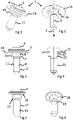
Figur 1 eine perspektivische Darstellung einer modularen Schraube gemäß einem ersten Ausführungsbeispiel, -
Figur 2 eine weitere perspektivische Darstellung der modularen Schraube, -
Figur 3 eine Seitenansicht der modularen Schraube, -
Figur 4 eine teilweise freigeschnittene Seitenansicht der modularen Schraube, -
Figur 5 eine Seitenansicht eines Schraubenkopfs und eines Schaftes der modularen Schraube, -
Figur 6 eine perspektivische Darstellung des Schraubenkopfes und des Schaftes der modularen Schraube, -
Figur 7 eine perspektivische Darstellung einer Spannscheibe der modularen Schraube, -
Figur 8 eine seitlich geschnittene Darstellung der Spannscheibe, -
Figur 9 eine Draufsicht auf die Spannscheibe, -
Figur 10 eine perspektivische Darstellung einer Unterlegscheibe der modularen Schraube, -
Figur 11 eine seitlich geschnittene Darstellung der Unterlegscheibe, und -
Figur 12 eine Draufsicht auf die Unterlegscheibe, -
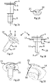
Figur 13 eine perspektivische Darstellung einer modularen Schraube gemäß einem zweiten Ausführungsbeispiel, -
Figur 14 eine Seitenansicht der modularen Schraube, -
Figur 15 eine Seitenansicht eines Schraubenkopfs und eines Schaftes der modularen Schraube, -
Figur 16 eine perspektivische Darstellung einer Unterlegscheibe, -
Figur 17 eine perspektivische Darstellung einer modularen Schraube gemäß einem dritten Ausführungsbeispiel, -
Figur 18 eine teilweise geschnittene Seitenansicht der modularen Schraube, -
Figur 19 eine weitere perspektivische Darstellung der modularen Schraube, -
Figur 20 eine Detailansicht der modularen Schraube ausFigur 19 , -
Figur 21 eine perspektivische Darstellung einer Spannscheibe mit Verbindungsmitteln, -
Figur 22 eine seitlich geschnittene Darstellung der Spannscheibe, -
Figur 23 eine Draufsicht auf die Spannscheibe, -
Figur 24 ein Schraubenkopf und ein Schaft der Schraube, und -
Figur 25 eine perspektivische Darstellung des Schraubenkopfes und der modularen Schraube. - Im Folgenden wird eine erfindungsgemäße modulare Schraube 1 anhand eines ersten Ausführungsbeispiels näher beschrieben (
Figuren 1 bis 12 ). - Die modulare Schraube 1 weist entlang einer sich in Axialrichtung 2 erstreckenden Längsachse 3 einen Schraubenkopf 4, einen ersten Funktionsabschnitt 5, einen zweiten Funktionsabschnitt 6, einen dritten Funktionsabschnitt 7 und einen vierten Funktionsabschnitt 8 auf.
- Am Schraubenkopf 4 ist ein beliebiger Antrieb 9 ausgebildet. Als Antrieb 9 kann ein Innen-oder Außensechskant, eine Schlitz- oder Kreuzschlitzverbindung oder ein Torx vorgesehen sein.
- An einer dem Antrieb 9 gegenüberliegenden Seite weist der Schraubenkopf 4 eine sich quer zur Axialrichtung erstreckende Anschlagfläche 10 auf.
- Benachbart zur Anschlagfläche 10 ist im ersten Funktionsabschnitt 5 eine Spannscheibe, vorzugsweise eine Tellerfeder, zum Erzeugen einer Vorspannung angeordnet. Die Tellerfeder ist in Axialrichtung ortsfest mit einem sich in Axialrichtung erstreckenden Schraubenschaft 11 verbunden.
- Die Spannscheibe 14 ist vorzugsweise als Tellerfeder ausgebildet und weist eine Durchgangsöffnung 19 auf.
- Der erste Funktionsabschnitt 5 mit der Spannscheibe 14 bildet einen Vorspannabschnitt 15 aus.
- Benachbart zum ersten Funktionsabschnitt ist in Axialrichtung 2 der zweite Funktionsabschnitt 6 in Form eines Kompressionsbegrenzungsabschnittes 12 vorgesehen. Der Kompressionsbegrenzungsabschnitt 12 ist in etwa zylindrisch ausgebildet. Er kann jedoch auch in Axialrichtung 2 kegelförmig aufweitend oder sich konusförmig verjüngend ausgebildet sein.
- Benachbart zum dritten Funktionsabschnitt 7 weist der Kompressionsbegrenzungsabschnitt 12 eine sich quer zur Axialrichtung erstreckende Anschlagfläche 13 auf.
- Eine Höhe des Kompressionsbegrenzungsabschnitts 12 ist in axialer Richtung 2 kleiner einer Höhe einer Durchgangsöffnung eines Bauteils, in dem der erste und der zweite Funktionsabschnitt 5, 6, 12, 15 anordbar sind.
- Im dritten Funktionsabschnitt 7 ist eine Unterlegscheibe 16 um die Längsachse 3 drehbar mit dem Schraubenschaft 11 verbunden bzw. an diesem gelagert und in Axialrichtung 2 ortsfest festgelegt.
- Die ortsfeste Festlegung in Axialrichtung der Unterlegscheibe 16 erfolgt dadurch, dass die Unterlegscheibe in Axialrichtung 2 durch Anlage an der Anschlagfläche 13 zweiten und einer Kante des vierten Funktionsabschnitt in etwa ortsfest festgelegt ist.
- Die Unterlegscheibe 16 weist eine Durchgangsöffnung 25 auf.
- Der dritte Funktionsabschnitt 7 mit der Unterlegscheibe 16 bildet einen Kraftverteilungsabschnitt 22 aus.
- Im vierten Funktionsabschnitt 8 ist an einer äußeren Mantelwandung des Schraubenschaftes 11 ein Außengewinde 17 ausgebildet.
- Der vierte Funktionsabschnitt 8 mit dem Außengewinde 17 bildet einen Gewindeabschnitt 23 aus.
- Ein Verfahren zum Herstellen einer modularen Schraube, umfasst die Folgenden Schritte
- Pressen eines Schraubenkopfes und eines Schaftes in einer Pressmaschine, Aufbringen einer Spann und/oder einer Unterlegscheibe in einer Walzmaschine, und Walzen eines Außengewindes in der Walzmaschine, und
- ggfs. Wärmebehandeln und/oder Beschichten der modularen Schraube.
- Bei der vorliegenden Erfindung hingegen wird somit zunächst ein Rohling der Schraube umfassend den Schraubenkopf und den Schaft mittels Pressen in der Pressmaschine hergestellt. Anschließend werden ungehärtete und unbeschichtete Scheiben und die Rohlinge der Walzmaschine zugeführt. Die Zuführung kann jeweils über entsprechende Zuführeinrichtungen, wie z.B. einen Verteilertopf oder eine Zuführschiene oder dergleichen erfolgen.
- In der Walzmaschine werden dann in einem Bereich vor entsprechenden Walzbacken zum Gewindewalzen die Spann- und/oder die Unterlegscheibe auf den Schaft aufgebracht. Danach wird das Außengewinde mittels der Walzbacken in der Walzmaschine gewalzt bzw. hergestellt.
- Daraufhin können die Schraube und die Scheibe/-n gemeinsam gehärtet und beschichtet werden, um die modulare Schraube auszubilden.
- Dementsprechend kann erfindungsgemäß auch eine entsprechende Vorrichtung zur Herstellung einer modularen Schraube vorgesehen sein, die die vorstehend aufgezeigte Press-und Walzmaschine umfasst.
- Im Folgenden wird eine erfindungsgemäße modulare Schraube 1 gemäß einem zweiten Ausführungsbeispiel näher beschrieben (
Figuren 13 bis 16 ). Sofern nichts anderes beschrieben ist, weist die modulare Schraube 1 gemäß dem zweiten Ausführungsbeispiel dieselben technischen Merkmale wie die modulare Schraube 1 gemäß dem ersten Ausführungsbeispiel auf. - Bei der modularen Schraube 1 gemäß dem zweiten Ausführungsbeispiel ist im Gegensatz zum ersten Ausführungsbeispiel keine Spannscheibe 14 vorgesehen.
- Die modulare Schraube 1 gemäß dem zweiten Ausführungsbeispiel weist demgemäß in Axialrichtung 2 den Schraubenkopf 4, den ersten und den zweiten Funktionsabschnitt 5, 6, die im vorliegenden Ausführungsbeispiel als ein einziger Funktionsabschnitt ausgebildet sind, den dritten Funktionsabschnitt 7 und den vierten Funktionsabschnitt 8 auf.
- Der erste und der zweite Funktionsabschnitt 5 sind als Kompressionsbegrenzungsabschnitt 12 ausgebildet.
- Im dritten Funktionsabschnitt 7, der als Kraftverteilungsabschnitt ausgebildet ist, ist die Unterlegscheibe 16 angeordnet und mit dem Schraubenschaft um die Längsachse drehbar gelagert verbunden. Entsprechend dem ersten Ausführungsbeispiel ist die Schraube in Axialrichtung ortsfest durch Anlage an dem vierten und an dem ersten und zweiten Funktionsabschnitt angeordnet.
- Die Herstellung erfolgt analog zum ersten Ausführungsbeispiel vorzugsweise jedoch ohne Spannscheibe 16.
- Im Folgenden wird eine erfindungsgemäße modulare Schraube 1 gemäß einem dritten Ausführungsbeispiel erläutert (
Figuren 17 bis 25 ). Sofern nichts anderes beschrieben ist, weist die modulare Schraube 1 gemäß dem dritten Ausführungsbeispiel dieselben technischen Merkmale auf, wie die modulare Schrauben 1 gemäß dem ersten und dem zweiten Ausführungsbeispiel. - Die modulare Schraube gemäß dem dritten Ausführungsbeispiel umfasst in Axialrichtung 2 den Schraubenkopf 4 und einen entsprechenden Schraubenschaft 11.
- Weiterhin weist die Schraube 1 in Axialrichtung 2 den ersten Funktionsabschnitt 5, den zweiten Funktionsabschnitt 6, und den vierten Funktionsabschnitt 8 auf.
- Im ersten Funktionsabschnitt 5, der als Vorspannabschnitt 15 ausgebildet ist, ist gemäß dem ersten Ausführungsbeispiel eine Spannscheibe 16 angeordnet.
- Die Schraube 1 und die Spannscheibe 16 können gemäß dem ersten Ausführungsbeispiel gestellt sein.
- Alternativ ist gemäß dem dritten Ausführungsbeispiel vorgesehen, dass die Spannscheibe 16 Verbindungsmittel 21 aufweist, über die die Spannscheibe mittels Reib- und/oder Formschluss ortsfest mit dem Schaft 11 verbunden ist.
- Die Spannscheibe ist als Tellerfeder ausgebildet und weist eine Durchgangsöffnung 19 auf. In der Durchgangsöffnung 19 sind drei, sich in radialer Richtung 20 nach innen in Richtung Längsachse 3 ersteckende Verbindungsmittel 21 radial umlaufend und gleich beabstandet voneinander angeordnet.
- Die Verbindungsmittel sind als Laschen 21 ausgebildet, die entlang einer Kreisrichtung verlaufende Kontaktkanten 22 aufweisen. Die Kontaktkanten 22 der Verbindungsmittel 21 verbinden die Spannscheibe 14 mittels Reibschluss mit dem Schraubenschaft im Bereich des ersten Funktionsabschnitts.
- Die Spannscheibe 16 kann gemäß diesem Ausführungsbeispiel mittels Pressen mit dem Schraubenschaft 11 verbunden sein.
-
- 1
- Schraube
- 2
- Axialrichtung
- 3
- Längsachse
- 4
- Schraubenkopf
- 5
- erster Funktionsabschnitt
- 6
- zweiter Funktionsabschnitt
- 7
- dritter Funktionsabschnitt
- 8
- vierter Funktionsabschnitt
- 9
- Antrieb
- 10
- Anschlagfläche
- 11
- Schraubenschaft
- 12
- Kompressionsbegrenzungsabschnitt
- 13
- Anschlagfläche
- 14
- Spannscheibe
- 15
- Vorspannabschnitt
- 16
- Unterlegscheibe
- 17
- Außengewinde
- 18 19
- Durchgangsöffnung
- 20
- Radiale Richtung
- 21
- Verbindungsmittel
- 22
- Kontaktkante
- 23
- Kraftübertragungsabschnitt
- 24
- Gewindeabschnitt
- 25
- Durchgangsöffnung
Claims (10)
- Modulare Schraube (1), wobei die Schraube (1) in einer Axialrichtung (2) die folgenden Elemente umfassteinen Schraubenkopf (4),einen Schaft miteinem zweiten Funktionsabschnitt (6),einem dritten Funktionsabschnitt (7), zum Verteilen einer Vorspannkraft, wobei im dritten Funktionsabschnitt (7) eine Unterlegscheibe (16) angeordnet ist, die um eine Längsachse (3) der Schraube (1) drehbar gelagert ist, undeinem vierten Funktionsabschnitt (8) mit einem Außengewinde (17), undwobei die Unterlegscheibe (16) in Axialrichtung (2) durch Anlage an dem zweiten und dem vierten Funktionsabschnitt (6, 8) in etwa ortsfest festgelegt ist.
- Modulare Schraube (1) gemäß Anspruch 1,
dadurch gekennzeichnet,
dass in einem ersten Funktionsabschnitt (5) zwischen Schraubenkopf (4) und zweitem Funktionsabschnitt (6) eine Spannscheibe (14) angeordnet ist, wobei die Spannscheibe (14) vorzugsweise als Tellerfeder ausgebildet ist und mit dem Schaft ortsfest verbunden und festgelegt ist, sodass des erste Funktionsabschnitt (5) einen Vorspannabschnitt (15) ausbildet. - Modulare Schraube (1) gemäß Anspruch 1 oder 2,
dadurch gekennzeichnet,
dass der zweite Funktionsabschnitt (6) ein Kompressionsbegrenzungsabschnitt (12) ist, dessen Durchmesser vorzugsweise größer als ein Durchmesser des Außengewindes (17) ist. - Modulare Schraube (1) gemäß einem der Ansprüche 1 bis 3,
dadurch gekennzeichnet,
dass die Unterlegscheibe (16) einen größeren Durchmesser aufweist als der zweite Funktionsabschnitt (6). - Modulare Schraube (1) gemäß einem der Ansprüche 1 bis 4,
dadurch gekennzeichnet,
dass eine Länge des zweiten Funktionsabschnittes (6) und des dritten Funktionsabschnittes (7) in axialer Richtung kleiner einer Höhe einer Durchgangsöffnung (19) eines Bauteils in axialer Richtung ist in dem die Schraube (1) anordbar ist. - Modulare Schraube (1) gemäß einem der Ansprüche 1 bis 5, hergestellt durch
Pressen des Schraubenkopfes (4) und des Schaftes in einer Pressmaschine, Aufbringen von Unterlegscheibe (16) und/oder Spannscheibe (14) auf den Schaft vorzugsweise in einer Walzmaschine, und
Walzen des Außengewindes (17) in der Walzmaschine. - Modulare Schraube (1), wobei die Schraube (1) in einer Axialrichtung (2) die folgenden Elemente umfassteinen Schraubenkopf (4),einen Schaft miteinem ersten Funktionsabschnitt (5), zum Aufbringen einer Vorspannkraft, wobei im ersten Funktionsabschnitt (5) benachbart zum Schraubenkopf (4) eine Spannscheibe (14) angeordnet ist, wobei die Spannscheibe (14) vorzugsweise als Tellerfeder ausgebildet ist und mit dem Schaft ortsfest verbunden und festgelegt ist,einem zweiten Funktionsabschnitt (6),und einem vierten Funktionsabschnitt (8) mit einem Außengewinde (17).
- Modulare Schraube (1) gemäß Anspruch 7,
dadurch gekennzeichnet,
dass die Spannscheibe (14) ein Verbindungsmittel (21) aufweist über das die Spannscheibe (14) mittels Reib- und oder Formschluss ortsfest mit dem Schaft verbunden ist, wobei das Verbindungsmittel (21), zum Bereitstellen einer reibschlüssigen Verbindung ausgebildet ist. - Modulare Schraube (1) gemäß Anspruch 8,
dadurch gekennzeichnet,
dass die Spannscheibe (14) eine Durchgangsöffnung (19) aufweist, wobei das Verbindungsmittel (21) als sich von einem Rand der Durchgangsöffnung (19) in radialer Richtung nach innen in Richtung Längsachse (3) gerichtete Laschen mit Haltekanten ausgebildet ist. - Verfahren zum Herstellen einer Schraube (1), insbesondere nach einem der Ansprüche 1 bis 7, umfassend die folgenden Schritte,Pressen eines Schraubenkopfes (4) und eines Schaftes in einer Pressmaschine,Aufbringen einer Spann und/oder einer Unterlegscheibe (14, 16) in einer Zuführeinrichtung einer Walzmaschine, undWalzen eines Außengewindes (17) in der Walzmaschine, undvorzugsweise Wärmebehandeln und/oder Beschichten der modularen Schraube (1).
Applications Claiming Priority (1)
| Application Number | Priority Date | Filing Date | Title |
|---|---|---|---|
| DE102021103410 | 2021-02-12 |
Publications (2)
| Publication Number | Publication Date |
|---|---|
| EP4043739A1 true EP4043739A1 (de) | 2022-08-17 |
| EP4043739B1 EP4043739B1 (de) | 2024-07-31 |
Family
ID=79287985
Family Applications (1)
| Application Number | Title | Priority Date | Filing Date |
|---|---|---|---|
| EP22150752.8A Active EP4043739B1 (de) | 2021-02-12 | 2022-01-10 | Modulare schraube sowie verfahren zur herstellung einer modularen schraube |
Country Status (4)
| Country | Link |
|---|---|
| US (1) | US12006961B2 (de) |
| EP (1) | EP4043739B1 (de) |
| KR (1) | KR20220115877A (de) |
| CN (1) | CN114922893A (de) |
Citations (5)
| Publication number | Priority date | Publication date | Assignee | Title |
|---|---|---|---|---|
| US3862458A (en) * | 1972-10-02 | 1975-01-28 | Textron Inc | Pre-assembled terminal screw and washers and method of manufacture |
| US4941787A (en) * | 1989-10-05 | 1990-07-17 | Consulier Industries, Inc. | Locking mechanism for fastener |
| DE19916989A1 (de) * | 1999-04-15 | 2000-10-19 | Bauer Christian Gmbh & Co | Definiert spannbares elastisches Spannelement |
| CN204729438U (zh) * | 2015-06-14 | 2015-10-28 | 山东临大锐思智造技术有限公司 | 一种新型组合不脱出螺钉 |
| EP2638299B1 (de) * | 2010-11-10 | 2016-03-23 | Arçelik Anonim Sirketi | Waschmaschine |
Family Cites Families (17)
| Publication number | Priority date | Publication date | Assignee | Title |
|---|---|---|---|---|
| US1868415A (en) * | 1929-10-31 | 1932-07-19 | Gundersen Einar | Method of manufacturing screws with one or two appending washers |
| US2303224A (en) * | 1938-08-27 | 1942-11-24 | Illinois Tool Works | Method and means for assembling screws and lock washers |
| US3181584A (en) * | 1959-08-21 | 1965-05-04 | George K Garrett Company | Screw-and-washer pre-assembly |
| US3152507A (en) * | 1961-07-05 | 1964-10-13 | Illinois Tool Works | Fastener having a grooved and slotted head |
| JPS507553B1 (de) * | 1970-05-06 | 1975-03-26 | ||
| US3816820A (en) * | 1972-10-02 | 1974-06-11 | Textron Inc | Pre-assembled terminal screw and washers and method of manufacture |
| GB1493220A (en) * | 1976-10-12 | 1977-11-30 | Pye Ltd | Screw or nut and a washer intended to be held captive thereon |
| US4321001A (en) * | 1980-06-19 | 1982-03-23 | Peter Gruich | Fabricated industrial fastener |
| JP2809584B2 (ja) * | 1993-12-13 | 1998-10-08 | 光洋器材株式会社 | デッキプレート用インサート |
| US20070274805A1 (en) * | 2006-05-26 | 2007-11-29 | Nebl David R | Fastener and assembly therewith |
| DE102006059232B3 (de) * | 2006-12-13 | 2008-06-12 | Richard Bergner Verbindungstechnik Gmbh & Co. Kg | Montageeinheit und eine solche umfassendes Bauteil |
| US20090232618A1 (en) * | 2008-03-13 | 2009-09-17 | The Timken Company | Fastener assembly |
| US8920092B2 (en) * | 2011-04-18 | 2014-12-30 | D'addario & Company, Inc. | Rotatable end pin for instrument strap |
| CN203130751U (zh) * | 2013-02-25 | 2013-08-14 | 中国石油化工股份有限公司 | 一种碟簧金属橡胶复合缓冲防松弛元件 |
| CN205190502U (zh) * | 2015-11-02 | 2016-04-27 | 长兴宏利五金配件有限公司 | 一体式螺栓 |
| CN106089925A (zh) * | 2016-08-25 | 2016-11-09 | 安徽六方重联机械股份有限公司 | 弹性预紧型螺栓 |
| PT3938666T (pt) * | 2019-03-15 | 2024-11-13 | Acument Intellectual Properties Llc | União aparafusada utilizando manga deformável com ranhuras longitudinais |
-
2022
- 2022-01-10 EP EP22150752.8A patent/EP4043739B1/de active Active
- 2022-02-01 US US17/590,399 patent/US12006961B2/en active Active
- 2022-02-09 KR KR1020220016848A patent/KR20220115877A/ko active Pending
- 2022-02-10 CN CN202210124101.4A patent/CN114922893A/zh active Pending
Patent Citations (5)
| Publication number | Priority date | Publication date | Assignee | Title |
|---|---|---|---|---|
| US3862458A (en) * | 1972-10-02 | 1975-01-28 | Textron Inc | Pre-assembled terminal screw and washers and method of manufacture |
| US4941787A (en) * | 1989-10-05 | 1990-07-17 | Consulier Industries, Inc. | Locking mechanism for fastener |
| DE19916989A1 (de) * | 1999-04-15 | 2000-10-19 | Bauer Christian Gmbh & Co | Definiert spannbares elastisches Spannelement |
| EP2638299B1 (de) * | 2010-11-10 | 2016-03-23 | Arçelik Anonim Sirketi | Waschmaschine |
| CN204729438U (zh) * | 2015-06-14 | 2015-10-28 | 山东临大锐思智造技术有限公司 | 一种新型组合不脱出螺钉 |
Also Published As
| Publication number | Publication date |
|---|---|
| KR20220115877A (ko) | 2022-08-19 |
| US12006961B2 (en) | 2024-06-11 |
| US20220260105A1 (en) | 2022-08-18 |
| EP4043739B1 (de) | 2024-07-31 |
| CN114922893A (zh) | 2022-08-19 |
Similar Documents
| Publication | Publication Date | Title |
|---|---|---|
| DE3620005C1 (en) | Device for adjusting a first structural part relative to a second structural part | |
| DE10034748B4 (de) | Lösbares Verbindungselement für ein Fahrzeugrad, mit einem Schraubteil und einem Stützring | |
| EP3036443B1 (de) | Verfahren zum verbinden von bauteilen sowie baugruppe | |
| EP2130722B1 (de) | Toleranzausgleichselement | |
| DE102006004678A1 (de) | Montageeinheit für die Befestigungsöse eines Gurtschlosses | |
| EP3445980A1 (de) | Axialkugelgelenk und längeneinstellbarer zweipunktlenker mit einem solchen axialkugelgelenk | |
| DE102018126958A1 (de) | Verbindungseinheit zum Verbinden von zwei Bauteilen mit einem Abstand dazwischen | |
| EP1205676B1 (de) | Montageeinheit aus einem Bauteil und mindestens einer Schraube | |
| EP1308638B1 (de) | Sicherungsmutter | |
| EP3765750B1 (de) | Ein verbindungselement mit aussenhülse sowie entsprechende verbindungs- und herstellungsverfahren | |
| EP0759377B1 (de) | Anordnung zur Einstellung des Reflektorneigungenswinkels bei Frontscheinwerfeern eines Kraftfahrzeuges | |
| EP4043739B1 (de) | Modulare schraube sowie verfahren zur herstellung einer modularen schraube | |
| DE102020211158B4 (de) | Passverbindung | |
| DE4307092B4 (de) | Mutter, insbesondere Radmutter | |
| EP1276996B1 (de) | Montageeinheit aus einem bauteil und mindestens einer gewindeformenden schraube | |
| EP4411151B1 (de) | Verstellelement mit dämpfender befestigungshülse sowie ein installations- und ein herstellungsverfahren dafür | |
| DE102006022382A1 (de) | Vorrichtung und Verfahren zur Befestigung eines Wischermotors an ein Wischergestänge | |
| EP1712326A2 (de) | Befestigungselement und Verfahren zu seiner Herstellung | |
| DE102011013389A1 (de) | Verbindungsanordnung zweier zumindest im Wesentlichen aus einem Leichtmetall gebildeten Bauteile | |
| WO2023131430A1 (de) | Befestigungsanordnung und korrespondierende sensoranordnung | |
| WO2022207295A1 (de) | Fixierbolzen | |
| DE102020125085B4 (de) | Vormontierte Baugruppe für die Verwendung zum Verbinden zweier Bauteile und Verfahren zum Herstellen einer vormontierten Baugruppe | |
| EP4095397B1 (de) | Vorrichtung zum ausgleichen von toleranzen zwischen zwei miteinander zu verbindenden bauteilen | |
| DE102019107888A1 (de) | Halteanordnung eines ersten Bauteils an einem zweiten Bauteil eines Kraftfahrzeugs sowie Verfahren zum Herstellen einer Halteanordnung | |
| DE102023122430A1 (de) | Befestigungselement, Befestigungsanordnung und Verfahren zum Befestigen |
Legal Events
| Date | Code | Title | Description |
|---|---|---|---|
| PUAI | Public reference made under article 153(3) epc to a published international application that has entered the european phase |
Free format text: ORIGINAL CODE: 0009012 |
|
| STAA | Information on the status of an ep patent application or granted ep patent |
Free format text: STATUS: THE APPLICATION HAS BEEN PUBLISHED |
|
| AK | Designated contracting states |
Kind code of ref document: A1 Designated state(s): AL AT BE BG CH CY CZ DE DK EE ES FI FR GB GR HR HU IE IS IT LI LT LU LV MC MK MT NL NO PL PT RO RS SE SI SK SM TR |
|
| STAA | Information on the status of an ep patent application or granted ep patent |
Free format text: STATUS: REQUEST FOR EXAMINATION WAS MADE |
|
| 17P | Request for examination filed |
Effective date: 20230214 |
|
| RBV | Designated contracting states (corrected) |
Designated state(s): AL AT BE BG CH CY CZ DE DK EE ES FI FR GB GR HR HU IE IS IT LI LT LU LV MC MK MT NL NO PL PT RO RS SE SI SK SM TR |
|
| GRAP | Despatch of communication of intention to grant a patent |
Free format text: ORIGINAL CODE: EPIDOSNIGR1 |
|
| STAA | Information on the status of an ep patent application or granted ep patent |
Free format text: STATUS: GRANT OF PATENT IS INTENDED |
|
| INTG | Intention to grant announced |
Effective date: 20240221 |
|
| GRAS | Grant fee paid |
Free format text: ORIGINAL CODE: EPIDOSNIGR3 |
|
| GRAA | (expected) grant |
Free format text: ORIGINAL CODE: 0009210 |
|
| STAA | Information on the status of an ep patent application or granted ep patent |
Free format text: STATUS: THE PATENT HAS BEEN GRANTED |
|
| AK | Designated contracting states |
Kind code of ref document: B1 Designated state(s): AL AT BE BG CH CY CZ DE DK EE ES FI FR GB GR HR HU IE IS IT LI LT LU LV MC MK MT NL NO PL PT RO RS SE SI SK SM TR |
|
| REG | Reference to a national code |
Ref country code: CH Ref legal event code: EP Ref country code: GB Ref legal event code: FG4D Free format text: NOT ENGLISH |
|
| P01 | Opt-out of the competence of the unified patent court (upc) registered |
Free format text: CASE NUMBER: APP_41239/2024 Effective date: 20240711 |
|
| REG | Reference to a national code |
Ref country code: DE Ref legal event code: R096 Ref document number: 502022001323 Country of ref document: DE |
|
| REG | Reference to a national code |
Ref country code: IE Ref legal event code: FG4D Free format text: LANGUAGE OF EP DOCUMENT: GERMAN |
|
| REG | Reference to a national code |
Ref country code: LT Ref legal event code: MG9D |
|
| REG | Reference to a national code |
Ref country code: NL Ref legal event code: MP Effective date: 20240731 |
|
| PG25 | Lapsed in a contracting state [announced via postgrant information from national office to epo] |
Ref country code: PT Free format text: LAPSE BECAUSE OF FAILURE TO SUBMIT A TRANSLATION OF THE DESCRIPTION OR TO PAY THE FEE WITHIN THE PRESCRIBED TIME-LIMIT Effective date: 20241202 |
|
| PG25 | Lapsed in a contracting state [announced via postgrant information from national office to epo] |
Ref country code: PT Free format text: LAPSE BECAUSE OF FAILURE TO SUBMIT A TRANSLATION OF THE DESCRIPTION OR TO PAY THE FEE WITHIN THE PRESCRIBED TIME-LIMIT Effective date: 20241202 |
|
| PG25 | Lapsed in a contracting state [announced via postgrant information from national office to epo] |
Ref country code: NO Free format text: LAPSE BECAUSE OF FAILURE TO SUBMIT A TRANSLATION OF THE DESCRIPTION OR TO PAY THE FEE WITHIN THE PRESCRIBED TIME-LIMIT Effective date: 20241031 |
|
| PG25 | Lapsed in a contracting state [announced via postgrant information from national office to epo] |
Ref country code: NL Free format text: LAPSE BECAUSE OF FAILURE TO SUBMIT A TRANSLATION OF THE DESCRIPTION OR TO PAY THE FEE WITHIN THE PRESCRIBED TIME-LIMIT Effective date: 20240731 Ref country code: FI Free format text: LAPSE BECAUSE OF FAILURE TO SUBMIT A TRANSLATION OF THE DESCRIPTION OR TO PAY THE FEE WITHIN THE PRESCRIBED TIME-LIMIT Effective date: 20240731 Ref country code: PL Free format text: LAPSE BECAUSE OF FAILURE TO SUBMIT A TRANSLATION OF THE DESCRIPTION OR TO PAY THE FEE WITHIN THE PRESCRIBED TIME-LIMIT Effective date: 20240731 Ref country code: GR Free format text: LAPSE BECAUSE OF FAILURE TO SUBMIT A TRANSLATION OF THE DESCRIPTION OR TO PAY THE FEE WITHIN THE PRESCRIBED TIME-LIMIT Effective date: 20241101 |
|
| PG25 | Lapsed in a contracting state [announced via postgrant information from national office to epo] |
Ref country code: BG Free format text: LAPSE BECAUSE OF FAILURE TO SUBMIT A TRANSLATION OF THE DESCRIPTION OR TO PAY THE FEE WITHIN THE PRESCRIBED TIME-LIMIT Effective date: 20240731 |
|
| PG25 | Lapsed in a contracting state [announced via postgrant information from national office to epo] |
Ref country code: LV Free format text: LAPSE BECAUSE OF FAILURE TO SUBMIT A TRANSLATION OF THE DESCRIPTION OR TO PAY THE FEE WITHIN THE PRESCRIBED TIME-LIMIT Effective date: 20240731 |
|
| PG25 | Lapsed in a contracting state [announced via postgrant information from national office to epo] |
Ref country code: IS Free format text: LAPSE BECAUSE OF FAILURE TO SUBMIT A TRANSLATION OF THE DESCRIPTION OR TO PAY THE FEE WITHIN THE PRESCRIBED TIME-LIMIT Effective date: 20241130 |
|
| PG25 | Lapsed in a contracting state [announced via postgrant information from national office to epo] |
Ref country code: HR Free format text: LAPSE BECAUSE OF FAILURE TO SUBMIT A TRANSLATION OF THE DESCRIPTION OR TO PAY THE FEE WITHIN THE PRESCRIBED TIME-LIMIT Effective date: 20240731 |
|
| PG25 | Lapsed in a contracting state [announced via postgrant information from national office to epo] |
Ref country code: RS Free format text: LAPSE BECAUSE OF FAILURE TO SUBMIT A TRANSLATION OF THE DESCRIPTION OR TO PAY THE FEE WITHIN THE PRESCRIBED TIME-LIMIT Effective date: 20241031 Ref country code: ES Free format text: LAPSE BECAUSE OF FAILURE TO SUBMIT A TRANSLATION OF THE DESCRIPTION OR TO PAY THE FEE WITHIN THE PRESCRIBED TIME-LIMIT Effective date: 20240731 |
|
| PG25 | Lapsed in a contracting state [announced via postgrant information from national office to epo] |
Ref country code: RS Free format text: LAPSE BECAUSE OF FAILURE TO SUBMIT A TRANSLATION OF THE DESCRIPTION OR TO PAY THE FEE WITHIN THE PRESCRIBED TIME-LIMIT Effective date: 20241031 Ref country code: PL Free format text: LAPSE BECAUSE OF FAILURE TO SUBMIT A TRANSLATION OF THE DESCRIPTION OR TO PAY THE FEE WITHIN THE PRESCRIBED TIME-LIMIT Effective date: 20240731 Ref country code: NO Free format text: LAPSE BECAUSE OF FAILURE TO SUBMIT A TRANSLATION OF THE DESCRIPTION OR TO PAY THE FEE WITHIN THE PRESCRIBED TIME-LIMIT Effective date: 20241031 Ref country code: NL Free format text: LAPSE BECAUSE OF FAILURE TO SUBMIT A TRANSLATION OF THE DESCRIPTION OR TO PAY THE FEE WITHIN THE PRESCRIBED TIME-LIMIT Effective date: 20240731 Ref country code: LV Free format text: LAPSE BECAUSE OF FAILURE TO SUBMIT A TRANSLATION OF THE DESCRIPTION OR TO PAY THE FEE WITHIN THE PRESCRIBED TIME-LIMIT Effective date: 20240731 Ref country code: IS Free format text: LAPSE BECAUSE OF FAILURE TO SUBMIT A TRANSLATION OF THE DESCRIPTION OR TO PAY THE FEE WITHIN THE PRESCRIBED TIME-LIMIT Effective date: 20241130 Ref country code: HR Free format text: LAPSE BECAUSE OF FAILURE TO SUBMIT A TRANSLATION OF THE DESCRIPTION OR TO PAY THE FEE WITHIN THE PRESCRIBED TIME-LIMIT Effective date: 20240731 Ref country code: GR Free format text: LAPSE BECAUSE OF FAILURE TO SUBMIT A TRANSLATION OF THE DESCRIPTION OR TO PAY THE FEE WITHIN THE PRESCRIBED TIME-LIMIT Effective date: 20241101 Ref country code: FI Free format text: LAPSE BECAUSE OF FAILURE TO SUBMIT A TRANSLATION OF THE DESCRIPTION OR TO PAY THE FEE WITHIN THE PRESCRIBED TIME-LIMIT Effective date: 20240731 Ref country code: ES Free format text: LAPSE BECAUSE OF FAILURE TO SUBMIT A TRANSLATION OF THE DESCRIPTION OR TO PAY THE FEE WITHIN THE PRESCRIBED TIME-LIMIT Effective date: 20240731 Ref country code: BG Free format text: LAPSE BECAUSE OF FAILURE TO SUBMIT A TRANSLATION OF THE DESCRIPTION OR TO PAY THE FEE WITHIN THE PRESCRIBED TIME-LIMIT Effective date: 20240731 |
|
| PG25 | Lapsed in a contracting state [announced via postgrant information from national office to epo] |
Ref country code: RO Free format text: LAPSE BECAUSE OF FAILURE TO SUBMIT A TRANSLATION OF THE DESCRIPTION OR TO PAY THE FEE WITHIN THE PRESCRIBED TIME-LIMIT Effective date: 20240731 Ref country code: DK Free format text: LAPSE BECAUSE OF FAILURE TO SUBMIT A TRANSLATION OF THE DESCRIPTION OR TO PAY THE FEE WITHIN THE PRESCRIBED TIME-LIMIT Effective date: 20240731 Ref country code: SM Free format text: LAPSE BECAUSE OF FAILURE TO SUBMIT A TRANSLATION OF THE DESCRIPTION OR TO PAY THE FEE WITHIN THE PRESCRIBED TIME-LIMIT Effective date: 20240731 |
|
| PG25 | Lapsed in a contracting state [announced via postgrant information from national office to epo] |
Ref country code: EE Free format text: LAPSE BECAUSE OF FAILURE TO SUBMIT A TRANSLATION OF THE DESCRIPTION OR TO PAY THE FEE WITHIN THE PRESCRIBED TIME-LIMIT Effective date: 20240731 |
|
| PG25 | Lapsed in a contracting state [announced via postgrant information from national office to epo] |
Ref country code: CZ Free format text: LAPSE BECAUSE OF FAILURE TO SUBMIT A TRANSLATION OF THE DESCRIPTION OR TO PAY THE FEE WITHIN THE PRESCRIBED TIME-LIMIT Effective date: 20240731 |
|
| PG25 | Lapsed in a contracting state [announced via postgrant information from national office to epo] |
Ref country code: IT Free format text: LAPSE BECAUSE OF FAILURE TO SUBMIT A TRANSLATION OF THE DESCRIPTION OR TO PAY THE FEE WITHIN THE PRESCRIBED TIME-LIMIT Effective date: 20240731 Ref country code: SK Free format text: LAPSE BECAUSE OF FAILURE TO SUBMIT A TRANSLATION OF THE DESCRIPTION OR TO PAY THE FEE WITHIN THE PRESCRIBED TIME-LIMIT Effective date: 20240731 |
|
| REG | Reference to a national code |
Ref country code: DE Ref legal event code: R097 Ref document number: 502022001323 Country of ref document: DE |
|
| PLBE | No opposition filed within time limit |
Free format text: ORIGINAL CODE: 0009261 |
|
| STAA | Information on the status of an ep patent application or granted ep patent |
Free format text: STATUS: NO OPPOSITION FILED WITHIN TIME LIMIT |
|
| 26N | No opposition filed |
Effective date: 20250501 |
|
| REG | Reference to a national code |
Ref country code: CH Ref legal event code: PL |
|
| PG25 | Lapsed in a contracting state [announced via postgrant information from national office to epo] |
Ref country code: SE Free format text: LAPSE BECAUSE OF FAILURE TO SUBMIT A TRANSLATION OF THE DESCRIPTION OR TO PAY THE FEE WITHIN THE PRESCRIBED TIME-LIMIT Effective date: 20240731 |
|
| PG25 | Lapsed in a contracting state [announced via postgrant information from national office to epo] |
Ref country code: LU Free format text: LAPSE BECAUSE OF NON-PAYMENT OF DUE FEES Effective date: 20250110 Ref country code: MC Free format text: LAPSE BECAUSE OF FAILURE TO SUBMIT A TRANSLATION OF THE DESCRIPTION OR TO PAY THE FEE WITHIN THE PRESCRIBED TIME-LIMIT Effective date: 20240731 |
|
| PG25 | Lapsed in a contracting state [announced via postgrant information from national office to epo] |
Ref country code: BE Free format text: LAPSE BECAUSE OF NON-PAYMENT OF DUE FEES Effective date: 20250131 |
|
| PG25 | Lapsed in a contracting state [announced via postgrant information from national office to epo] |
Ref country code: FR Free format text: LAPSE BECAUSE OF NON-PAYMENT OF DUE FEES Effective date: 20250131 |
|
| PG25 | Lapsed in a contracting state [announced via postgrant information from national office to epo] |
Ref country code: CH Free format text: LAPSE BECAUSE OF NON-PAYMENT OF DUE FEES Effective date: 20250131 |
|
| REG | Reference to a national code |
Ref country code: BE Ref legal event code: MM Effective date: 20250131 |
|
| PG25 | Lapsed in a contracting state [announced via postgrant information from national office to epo] |
Ref country code: IE Free format text: LAPSE BECAUSE OF NON-PAYMENT OF DUE FEES Effective date: 20250110 |
|
| PGFP | Annual fee paid to national office [announced via postgrant information from national office to epo] |
Ref country code: DE Payment date: 20260128 Year of fee payment: 5 |
|
| PGFP | Annual fee paid to national office [announced via postgrant information from national office to epo] |
Ref country code: AT Payment date: 20260301 Year of fee payment: 5 |