EP4043703A1 - Drive system - Google Patents
Drive system Download PDFInfo
- Publication number
- EP4043703A1 EP4043703A1 EP20873794.0A EP20873794A EP4043703A1 EP 4043703 A1 EP4043703 A1 EP 4043703A1 EP 20873794 A EP20873794 A EP 20873794A EP 4043703 A1 EP4043703 A1 EP 4043703A1
- Authority
- EP
- European Patent Office
- Prior art keywords
- temperature
- oil
- lubricating oil
- motor
- catalyst
- Prior art date
- Legal status (The legal status is an assumption and is not a legal conclusion. Google has not performed a legal analysis and makes no representation as to the accuracy of the status listed.)
- Pending
Links
Images




Classifications
-
- H—ELECTRICITY
- H02—GENERATION; CONVERSION OR DISTRIBUTION OF ELECTRIC POWER
- H02K—DYNAMO-ELECTRIC MACHINES
- H02K9/00—Arrangements for cooling or ventilating
- H02K9/19—Arrangements for cooling or ventilating for machines with closed casing and closed-circuit cooling using a liquid cooling medium, e.g. oil
-
- B—PERFORMING OPERATIONS; TRANSPORTING
- B60—VEHICLES IN GENERAL
- B60K—ARRANGEMENT OR MOUNTING OF PROPULSION UNITS OR OF TRANSMISSIONS IN VEHICLES; ARRANGEMENT OR MOUNTING OF PLURAL DIVERSE PRIME-MOVERS IN VEHICLES; AUXILIARY DRIVES FOR VEHICLES; INSTRUMENTATION OR DASHBOARDS FOR VEHICLES; ARRANGEMENTS IN CONNECTION WITH COOLING, AIR INTAKE, GAS EXHAUST OR FUEL SUPPLY OF PROPULSION UNITS IN VEHICLES
- B60K11/00—Arrangement in connection with cooling of propulsion units
- B60K11/02—Arrangement in connection with cooling of propulsion units with liquid cooling
-
- B—PERFORMING OPERATIONS; TRANSPORTING
- B60—VEHICLES IN GENERAL
- B60K—ARRANGEMENT OR MOUNTING OF PROPULSION UNITS OR OF TRANSMISSIONS IN VEHICLES; ARRANGEMENT OR MOUNTING OF PLURAL DIVERSE PRIME-MOVERS IN VEHICLES; AUXILIARY DRIVES FOR VEHICLES; INSTRUMENTATION OR DASHBOARDS FOR VEHICLES; ARRANGEMENTS IN CONNECTION WITH COOLING, AIR INTAKE, GAS EXHAUST OR FUEL SUPPLY OF PROPULSION UNITS IN VEHICLES
- B60K6/00—Arrangement or mounting of plural diverse prime-movers for mutual or common propulsion, e.g. hybrid propulsion systems comprising electric motors and internal combustion engines
- B60K6/20—Arrangement or mounting of plural diverse prime-movers for mutual or common propulsion, e.g. hybrid propulsion systems comprising electric motors and internal combustion engines the prime-movers consisting of electric motors and internal combustion engines, e.g. HEVs
- B60K6/42—Arrangement or mounting of plural diverse prime-movers for mutual or common propulsion, e.g. hybrid propulsion systems comprising electric motors and internal combustion engines the prime-movers consisting of electric motors and internal combustion engines, e.g. HEVs characterised by the architecture of the hybrid electric vehicle
- B60K6/48—Parallel type
- B60K6/485—Motor-assist type
-
- B—PERFORMING OPERATIONS; TRANSPORTING
- B60—VEHICLES IN GENERAL
- B60W—CONJOINT CONTROL OF VEHICLE SUB-UNITS OF DIFFERENT TYPE OR DIFFERENT FUNCTION; CONTROL SYSTEMS SPECIALLY ADAPTED FOR HYBRID VEHICLES; ROAD VEHICLE DRIVE CONTROL SYSTEMS FOR PURPOSES NOT RELATED TO THE CONTROL OF A PARTICULAR SUB-UNIT
- B60W10/00—Conjoint control of vehicle sub-units of different type or different function
- B60W10/04—Conjoint control of vehicle sub-units of different type or different function including control of propulsion units
- B60W10/06—Conjoint control of vehicle sub-units of different type or different function including control of propulsion units including control of combustion engines
-
- B—PERFORMING OPERATIONS; TRANSPORTING
- B60—VEHICLES IN GENERAL
- B60W—CONJOINT CONTROL OF VEHICLE SUB-UNITS OF DIFFERENT TYPE OR DIFFERENT FUNCTION; CONTROL SYSTEMS SPECIALLY ADAPTED FOR HYBRID VEHICLES; ROAD VEHICLE DRIVE CONTROL SYSTEMS FOR PURPOSES NOT RELATED TO THE CONTROL OF A PARTICULAR SUB-UNIT
- B60W10/00—Conjoint control of vehicle sub-units of different type or different function
- B60W10/04—Conjoint control of vehicle sub-units of different type or different function including control of propulsion units
- B60W10/08—Conjoint control of vehicle sub-units of different type or different function including control of propulsion units including control of electric propulsion units, e.g. motors or generators
-
- B—PERFORMING OPERATIONS; TRANSPORTING
- B60—VEHICLES IN GENERAL
- B60W—CONJOINT CONTROL OF VEHICLE SUB-UNITS OF DIFFERENT TYPE OR DIFFERENT FUNCTION; CONTROL SYSTEMS SPECIALLY ADAPTED FOR HYBRID VEHICLES; ROAD VEHICLE DRIVE CONTROL SYSTEMS FOR PURPOSES NOT RELATED TO THE CONTROL OF A PARTICULAR SUB-UNIT
- B60W10/00—Conjoint control of vehicle sub-units of different type or different function
- B60W10/30—Conjoint control of vehicle sub-units of different type or different function including control of auxiliary equipment, e.g. air-conditioning compressors or oil pumps
-
- B—PERFORMING OPERATIONS; TRANSPORTING
- B60—VEHICLES IN GENERAL
- B60W—CONJOINT CONTROL OF VEHICLE SUB-UNITS OF DIFFERENT TYPE OR DIFFERENT FUNCTION; CONTROL SYSTEMS SPECIALLY ADAPTED FOR HYBRID VEHICLES; ROAD VEHICLE DRIVE CONTROL SYSTEMS FOR PURPOSES NOT RELATED TO THE CONTROL OF A PARTICULAR SUB-UNIT
- B60W20/00—Control systems specially adapted for hybrid vehicles
- B60W20/10—Controlling the power contribution of each of the prime movers to meet required power demand
- B60W20/15—Control strategies specially adapted for achieving a particular effect
- B60W20/16—Control strategies specially adapted for achieving a particular effect for reducing engine exhaust emissions
-
- F—MECHANICAL ENGINEERING; LIGHTING; HEATING; WEAPONS; BLASTING
- F01—MACHINES OR ENGINES IN GENERAL; ENGINE PLANTS IN GENERAL; STEAM ENGINES
- F01M—LUBRICATING OF MACHINES OR ENGINES IN GENERAL; LUBRICATING INTERNAL COMBUSTION ENGINES; CRANKCASE VENTILATING
- F01M5/00—Heating, cooling, or controlling temperature of lubricant; Lubrication means facilitating engine starting
-
- F—MECHANICAL ENGINEERING; LIGHTING; HEATING; WEAPONS; BLASTING
- F01—MACHINES OR ENGINES IN GENERAL; ENGINE PLANTS IN GENERAL; STEAM ENGINES
- F01N—GAS-FLOW SILENCERS OR EXHAUST APPARATUS FOR MACHINES OR ENGINES IN GENERAL; GAS-FLOW SILENCERS OR EXHAUST APPARATUS FOR INTERNAL-COMBUSTION ENGINES
- F01N3/00—Exhaust or silencing apparatus having means for purifying, rendering innocuous, or otherwise treating exhaust
- F01N3/02—Exhaust or silencing apparatus having means for purifying, rendering innocuous, or otherwise treating exhaust for cooling, or for removing solid constituents of, exhaust
- F01N3/04—Exhaust or silencing apparatus having means for purifying, rendering innocuous, or otherwise treating exhaust for cooling, or for removing solid constituents of, exhaust using liquids
- F01N3/043—Exhaust or silencing apparatus having means for purifying, rendering innocuous, or otherwise treating exhaust for cooling, or for removing solid constituents of, exhaust using liquids without contact between liquid and exhaust gases
-
- F—MECHANICAL ENGINEERING; LIGHTING; HEATING; WEAPONS; BLASTING
- F01—MACHINES OR ENGINES IN GENERAL; ENGINE PLANTS IN GENERAL; STEAM ENGINES
- F01N—GAS-FLOW SILENCERS OR EXHAUST APPARATUS FOR MACHINES OR ENGINES IN GENERAL; GAS-FLOW SILENCERS OR EXHAUST APPARATUS FOR INTERNAL-COMBUSTION ENGINES
- F01N3/00—Exhaust or silencing apparatus having means for purifying, rendering innocuous, or otherwise treating exhaust
- F01N3/08—Exhaust or silencing apparatus having means for purifying, rendering innocuous, or otherwise treating exhaust for rendering innocuous
- F01N3/10—Exhaust or silencing apparatus having means for purifying, rendering innocuous, or otherwise treating exhaust for rendering innocuous by thermal or catalytic conversion of noxious components of exhaust
-
- F—MECHANICAL ENGINEERING; LIGHTING; HEATING; WEAPONS; BLASTING
- F01—MACHINES OR ENGINES IN GENERAL; ENGINE PLANTS IN GENERAL; STEAM ENGINES
- F01N—GAS-FLOW SILENCERS OR EXHAUST APPARATUS FOR MACHINES OR ENGINES IN GENERAL; GAS-FLOW SILENCERS OR EXHAUST APPARATUS FOR INTERNAL-COMBUSTION ENGINES
- F01N3/00—Exhaust or silencing apparatus having means for purifying, rendering innocuous, or otherwise treating exhaust
- F01N3/08—Exhaust or silencing apparatus having means for purifying, rendering innocuous, or otherwise treating exhaust for rendering innocuous
- F01N3/10—Exhaust or silencing apparatus having means for purifying, rendering innocuous, or otherwise treating exhaust for rendering innocuous by thermal or catalytic conversion of noxious components of exhaust
- F01N3/18—Exhaust or silencing apparatus having means for purifying, rendering innocuous, or otherwise treating exhaust for rendering innocuous by thermal or catalytic conversion of noxious components of exhaust characterised by methods of operation; Control
- F01N3/20—Exhaust or silencing apparatus having means for purifying, rendering innocuous, or otherwise treating exhaust for rendering innocuous by thermal or catalytic conversion of noxious components of exhaust characterised by methods of operation; Control specially adapted for catalytic conversion
- F01N3/2006—Periodically heating or cooling catalytic reactors, e.g. at cold starting or overheating
-
- F—MECHANICAL ENGINEERING; LIGHTING; HEATING; WEAPONS; BLASTING
- F01—MACHINES OR ENGINES IN GENERAL; ENGINE PLANTS IN GENERAL; STEAM ENGINES
- F01N—GAS-FLOW SILENCERS OR EXHAUST APPARATUS FOR MACHINES OR ENGINES IN GENERAL; GAS-FLOW SILENCERS OR EXHAUST APPARATUS FOR INTERNAL-COMBUSTION ENGINES
- F01N3/00—Exhaust or silencing apparatus having means for purifying, rendering innocuous, or otherwise treating exhaust
- F01N3/08—Exhaust or silencing apparatus having means for purifying, rendering innocuous, or otherwise treating exhaust for rendering innocuous
- F01N3/10—Exhaust or silencing apparatus having means for purifying, rendering innocuous, or otherwise treating exhaust for rendering innocuous by thermal or catalytic conversion of noxious components of exhaust
- F01N3/24—Exhaust or silencing apparatus having means for purifying, rendering innocuous, or otherwise treating exhaust for rendering innocuous by thermal or catalytic conversion of noxious components of exhaust characterised by constructional aspects of converting apparatus
-
- F—MECHANICAL ENGINEERING; LIGHTING; HEATING; WEAPONS; BLASTING
- F01—MACHINES OR ENGINES IN GENERAL; ENGINE PLANTS IN GENERAL; STEAM ENGINES
- F01N—GAS-FLOW SILENCERS OR EXHAUST APPARATUS FOR MACHINES OR ENGINES IN GENERAL; GAS-FLOW SILENCERS OR EXHAUST APPARATUS FOR INTERNAL-COMBUSTION ENGINES
- F01N3/00—Exhaust or silencing apparatus having means for purifying, rendering innocuous, or otherwise treating exhaust
- F01N3/08—Exhaust or silencing apparatus having means for purifying, rendering innocuous, or otherwise treating exhaust for rendering innocuous
- F01N3/10—Exhaust or silencing apparatus having means for purifying, rendering innocuous, or otherwise treating exhaust for rendering innocuous by thermal or catalytic conversion of noxious components of exhaust
- F01N3/24—Exhaust or silencing apparatus having means for purifying, rendering innocuous, or otherwise treating exhaust for rendering innocuous by thermal or catalytic conversion of noxious components of exhaust characterised by constructional aspects of converting apparatus
- F01N3/28—Construction of catalytic reactors
- F01N3/2882—Catalytic reactors combined or associated with other devices, e.g. exhaust silencers or other exhaust purification devices
- F01N3/2889—Catalytic reactors combined or associated with other devices, e.g. exhaust silencers or other exhaust purification devices with heat exchangers in a single housing
-
- F—MECHANICAL ENGINEERING; LIGHTING; HEATING; WEAPONS; BLASTING
- F01—MACHINES OR ENGINES IN GENERAL; ENGINE PLANTS IN GENERAL; STEAM ENGINES
- F01P—COOLING OF MACHINES OR ENGINES IN GENERAL; COOLING OF INTERNAL-COMBUSTION ENGINES
- F01P3/00—Liquid cooling
- F01P3/12—Arrangements for cooling other engine or machine parts
-
- F—MECHANICAL ENGINEERING; LIGHTING; HEATING; WEAPONS; BLASTING
- F01—MACHINES OR ENGINES IN GENERAL; ENGINE PLANTS IN GENERAL; STEAM ENGINES
- F01P—COOLING OF MACHINES OR ENGINES IN GENERAL; COOLING OF INTERNAL-COMBUSTION ENGINES
- F01P3/00—Liquid cooling
- F01P3/20—Cooling circuits not specific to a single part of engine or machine
-
- H—ELECTRICITY
- H02—GENERATION; CONVERSION OR DISTRIBUTION OF ELECTRIC POWER
- H02K—DYNAMO-ELECTRIC MACHINES
- H02K7/00—Arrangements for handling mechanical energy structurally associated with dynamo-electric machines, e.g. structural association with mechanical driving motors or auxiliary dynamo-electric machines
- H02K7/10—Structural association with clutches, brakes, gears, pulleys or mechanical starters
- H02K7/116—Structural association with clutches, brakes, gears, pulleys or mechanical starters with gears
-
- B—PERFORMING OPERATIONS; TRANSPORTING
- B60—VEHICLES IN GENERAL
- B60K—ARRANGEMENT OR MOUNTING OF PROPULSION UNITS OR OF TRANSMISSIONS IN VEHICLES; ARRANGEMENT OR MOUNTING OF PLURAL DIVERSE PRIME-MOVERS IN VEHICLES; AUXILIARY DRIVES FOR VEHICLES; INSTRUMENTATION OR DASHBOARDS FOR VEHICLES; ARRANGEMENTS IN CONNECTION WITH COOLING, AIR INTAKE, GAS EXHAUST OR FUEL SUPPLY OF PROPULSION UNITS IN VEHICLES
- B60K1/00—Arrangement or mounting of electrical propulsion units
- B60K2001/003—Arrangement or mounting of electrical propulsion units with means for cooling the electrical propulsion units
- B60K2001/006—Arrangement or mounting of electrical propulsion units with means for cooling the electrical propulsion units the electric motors
-
- B—PERFORMING OPERATIONS; TRANSPORTING
- B60—VEHICLES IN GENERAL
- B60K—ARRANGEMENT OR MOUNTING OF PROPULSION UNITS OR OF TRANSMISSIONS IN VEHICLES; ARRANGEMENT OR MOUNTING OF PLURAL DIVERSE PRIME-MOVERS IN VEHICLES; AUXILIARY DRIVES FOR VEHICLES; INSTRUMENTATION OR DASHBOARDS FOR VEHICLES; ARRANGEMENTS IN CONNECTION WITH COOLING, AIR INTAKE, GAS EXHAUST OR FUEL SUPPLY OF PROPULSION UNITS IN VEHICLES
- B60K6/00—Arrangement or mounting of plural diverse prime-movers for mutual or common propulsion, e.g. hybrid propulsion systems comprising electric motors and internal combustion engines
- B60K6/20—Arrangement or mounting of plural diverse prime-movers for mutual or common propulsion, e.g. hybrid propulsion systems comprising electric motors and internal combustion engines the prime-movers consisting of electric motors and internal combustion engines, e.g. HEVs
- B60K6/42—Arrangement or mounting of plural diverse prime-movers for mutual or common propulsion, e.g. hybrid propulsion systems comprising electric motors and internal combustion engines the prime-movers consisting of electric motors and internal combustion engines, e.g. HEVs characterised by the architecture of the hybrid electric vehicle
- B60K6/48—Parallel type
- B60K2006/4825—Electric machine connected or connectable to gearbox input shaft
-
- B—PERFORMING OPERATIONS; TRANSPORTING
- B60—VEHICLES IN GENERAL
- B60W—CONJOINT CONTROL OF VEHICLE SUB-UNITS OF DIFFERENT TYPE OR DIFFERENT FUNCTION; CONTROL SYSTEMS SPECIALLY ADAPTED FOR HYBRID VEHICLES; ROAD VEHICLE DRIVE CONTROL SYSTEMS FOR PURPOSES NOT RELATED TO THE CONTROL OF A PARTICULAR SUB-UNIT
- B60W2510/00—Input parameters relating to a particular sub-units
- B60W2510/06—Combustion engines, Gas turbines
-
- B—PERFORMING OPERATIONS; TRANSPORTING
- B60—VEHICLES IN GENERAL
- B60W—CONJOINT CONTROL OF VEHICLE SUB-UNITS OF DIFFERENT TYPE OR DIFFERENT FUNCTION; CONTROL SYSTEMS SPECIALLY ADAPTED FOR HYBRID VEHICLES; ROAD VEHICLE DRIVE CONTROL SYSTEMS FOR PURPOSES NOT RELATED TO THE CONTROL OF A PARTICULAR SUB-UNIT
- B60W2510/00—Input parameters relating to a particular sub-units
- B60W2510/06—Combustion engines, Gas turbines
- B60W2510/0676—Engine temperature
-
- B—PERFORMING OPERATIONS; TRANSPORTING
- B60—VEHICLES IN GENERAL
- B60W—CONJOINT CONTROL OF VEHICLE SUB-UNITS OF DIFFERENT TYPE OR DIFFERENT FUNCTION; CONTROL SYSTEMS SPECIALLY ADAPTED FOR HYBRID VEHICLES; ROAD VEHICLE DRIVE CONTROL SYSTEMS FOR PURPOSES NOT RELATED TO THE CONTROL OF A PARTICULAR SUB-UNIT
- B60W2510/00—Input parameters relating to a particular sub-units
- B60W2510/06—Combustion engines, Gas turbines
- B60W2510/068—Engine exhaust temperature
-
- B—PERFORMING OPERATIONS; TRANSPORTING
- B60—VEHICLES IN GENERAL
- B60W—CONJOINT CONTROL OF VEHICLE SUB-UNITS OF DIFFERENT TYPE OR DIFFERENT FUNCTION; CONTROL SYSTEMS SPECIALLY ADAPTED FOR HYBRID VEHICLES; ROAD VEHICLE DRIVE CONTROL SYSTEMS FOR PURPOSES NOT RELATED TO THE CONTROL OF A PARTICULAR SUB-UNIT
- B60W2510/00—Input parameters relating to a particular sub-units
- B60W2510/08—Electric propulsion units
- B60W2510/087—Temperature
-
- B—PERFORMING OPERATIONS; TRANSPORTING
- B60—VEHICLES IN GENERAL
- B60W—CONJOINT CONTROL OF VEHICLE SUB-UNITS OF DIFFERENT TYPE OR DIFFERENT FUNCTION; CONTROL SYSTEMS SPECIALLY ADAPTED FOR HYBRID VEHICLES; ROAD VEHICLE DRIVE CONTROL SYSTEMS FOR PURPOSES NOT RELATED TO THE CONTROL OF A PARTICULAR SUB-UNIT
- B60W2530/00—Input parameters relating to vehicle conditions or values, not covered by groups B60W2510/00 or B60W2520/00
- B60W2530/12—Catalyst or filter state
-
- B—PERFORMING OPERATIONS; TRANSPORTING
- B60—VEHICLES IN GENERAL
- B60W—CONJOINT CONTROL OF VEHICLE SUB-UNITS OF DIFFERENT TYPE OR DIFFERENT FUNCTION; CONTROL SYSTEMS SPECIALLY ADAPTED FOR HYBRID VEHICLES; ROAD VEHICLE DRIVE CONTROL SYSTEMS FOR PURPOSES NOT RELATED TO THE CONTROL OF A PARTICULAR SUB-UNIT
- B60W2710/00—Output or target parameters relating to a particular sub-units
- B60W2710/30—Auxiliary equipments
- B60W2710/305—Auxiliary equipments target power to auxiliaries
-
- F—MECHANICAL ENGINEERING; LIGHTING; HEATING; WEAPONS; BLASTING
- F01—MACHINES OR ENGINES IN GENERAL; ENGINE PLANTS IN GENERAL; STEAM ENGINES
- F01N—GAS-FLOW SILENCERS OR EXHAUST APPARATUS FOR MACHINES OR ENGINES IN GENERAL; GAS-FLOW SILENCERS OR EXHAUST APPARATUS FOR INTERNAL-COMBUSTION ENGINES
- F01N2240/00—Combination or association of two or more different exhaust treating devices, or of at least one such device with an auxiliary device, not covered by indexing codes F01N2230/00 or F01N2250/00, one of the devices being
- F01N2240/02—Combination or association of two or more different exhaust treating devices, or of at least one such device with an auxiliary device, not covered by indexing codes F01N2230/00 or F01N2250/00, one of the devices being a heat exchanger
-
- F—MECHANICAL ENGINEERING; LIGHTING; HEATING; WEAPONS; BLASTING
- F01—MACHINES OR ENGINES IN GENERAL; ENGINE PLANTS IN GENERAL; STEAM ENGINES
- F01P—COOLING OF MACHINES OR ENGINES IN GENERAL; COOLING OF INTERNAL-COMBUSTION ENGINES
- F01P2025/00—Measuring
- F01P2025/08—Temperature
- F01P2025/40—Oil temperature
-
- F—MECHANICAL ENGINEERING; LIGHTING; HEATING; WEAPONS; BLASTING
- F01—MACHINES OR ENGINES IN GENERAL; ENGINE PLANTS IN GENERAL; STEAM ENGINES
- F01P—COOLING OF MACHINES OR ENGINES IN GENERAL; COOLING OF INTERNAL-COMBUSTION ENGINES
- F01P2060/00—Cooling circuits using auxiliaries
- F01P2060/04—Lubricant cooler
- F01P2060/045—Lubricant cooler for transmissions
-
- F—MECHANICAL ENGINEERING; LIGHTING; HEATING; WEAPONS; BLASTING
- F28—HEAT EXCHANGE IN GENERAL
- F28D—HEAT-EXCHANGE APPARATUS, NOT PROVIDED FOR IN ANOTHER SUBCLASS, IN WHICH THE HEAT-EXCHANGE MEDIA DO NOT COME INTO DIRECT CONTACT
- F28D7/00—Heat-exchange apparatus having stationary tubular conduit assemblies for both heat-exchange media, the media being in contact with different sides of a conduit wall
- F28D7/10—Heat-exchange apparatus having stationary tubular conduit assemblies for both heat-exchange media, the media being in contact with different sides of a conduit wall the conduits being arranged one within the other, e.g. concentrically
- F28D7/106—Heat-exchange apparatus having stationary tubular conduit assemblies for both heat-exchange media, the media being in contact with different sides of a conduit wall the conduits being arranged one within the other, e.g. concentrically consisting of two coaxial conduits or modules of two coaxial conduits
-
- Y—GENERAL TAGGING OF NEW TECHNOLOGICAL DEVELOPMENTS; GENERAL TAGGING OF CROSS-SECTIONAL TECHNOLOGIES SPANNING OVER SEVERAL SECTIONS OF THE IPC; TECHNICAL SUBJECTS COVERED BY FORMER USPC CROSS-REFERENCE ART COLLECTIONS [XRACs] AND DIGESTS
- Y02—TECHNOLOGIES OR APPLICATIONS FOR MITIGATION OR ADAPTATION AGAINST CLIMATE CHANGE
- Y02T—CLIMATE CHANGE MITIGATION TECHNOLOGIES RELATED TO TRANSPORTATION
- Y02T10/00—Road transport of goods or passengers
- Y02T10/60—Other road transportation technologies with climate change mitigation effect
- Y02T10/64—Electric machine technologies in electromobility
Definitions
- This invention relates to a drive system, and more particularly, to a drive system including a motor and an engine.
- a vehicle including an engine warms up a three-way catalyst with a high-temperature exhaust gas emitted from the engine. Meanwhile, a vehicle including an engine and a motor, such as a hybrid vehicle, less frequently uses the engine to travel, and thus cannot sufficiently warm up the three-way catalyst with an exhaust gas. As a result, a temperature of the catalyst may decrease to lower exhaust-gas purification performance.
- Patent Literature 1 JP H6-276614A
- a drive apparatus for a hybrid vehicle which includes a power generator, a battery, an electric motor, a power conversion controller, a heating means, a temperature detecting means, and a refrigerant flow-path switching means.
- the power generator is rotationally driven by an engine to generate electric power.
- the battery converts an output from the power generator into DC power, and stores the DC power.
- the electric motor generates a driving force by using the power generator and the battery as power sources.
- the power conversion controller controls the electric motor.
- the heating means collects heat generated in the power conversion controller and the electric motor, and heats an engine-associated component.
- the temperature detecting means detects a temperature of the engine-associated component.
- the refrigerant flow-path switching means switches a flow path for refrigerant being the heating means based on the temperature detected by the temperature detecting means.
- Patent Literature 2 JP 2017-227163A
- a temperature raising apparatus including a retarder, an exhaust pipe, an exhaust-gas purification device, a refrigerant circulation pipe, and a pump.
- the retarder applies a braking force to a drive system of a vehicle when the vehicle decelerates.
- the exhaust pipe allows an exhaust gas from an engine mounted in the vehicle to flow therethrough.
- the exhaust-gas purification device includes a casing provided in the exhaust pipe, and the casing contains an exhaust-gas purification catalyst.
- the refrigerant circulation pipe includes a first heat exchange pipe portion, a second heat exchange pipe portion, a first connection pipe portion, and a second connection pipe portion, and encloses refrigerant therein.
- the first heat exchange pipe portion is mounted to an outer periphery of the retarder.
- the second heat exchange pipe portion is mounted to an outer periphery of the casing or on an outer periphery of the exhaust pipe so as to be located on an upstream side of the casing.
- the first connection pipe portion couples an outlet portion of the first heat exchange pipe portion and an inlet portion of the second heat exchange pipe portion to each other.
- the second connection pipe portion couples an outlet portion of the second heat exchange pipe portion and an inlet portion of the first heat exchange pipe portion to each other.
- the pump is driven to pump the refrigerant into the refrigerant circulation pipe and circulate the refrigerant therethrough when the retarder is actuated.
- Patent Literature 3 JP2000-265910A
- a hybrid vehicle including a self-ignition type gasoline engine, a motor generator, and a battery.
- the battery drives the motor generator. Output torque from the engine and the motor generator is transmitted to drive wheels via a transmission.
- the hybrid vehicle further includes a first chamber, a second chamber, a waste-heat absorbing means, a waste-heat guiding means, and an intake-air temperature raising means.
- the first chamber and the second chamber are provided in series on an upstream side in an intake air passage of the engine.
- the waste-heat absorbing means absorbs waste heat from at least one of the engine, the motor generator, and the transmission.
- the waste-heat guiding means guides the absorbed waste heat into the first chamber to raise an intake-air temperature in the first chamber.
- the intake-air temperature raising means raises an intake-air temperature in the second chamber with use of electric energy supplied from the battery.
- cooling water for the engine is used to warm up the catalyst.
- the cooling water has a low temperature, and is given at merely about 65°C to 90°C.
- a temperature of the catalyst does not sufficiently rise, providing only small effects of warming up the catalyst and keeping its temperature.
- a drive system capable of more efficiently warming up the catalyst and keeping its temperature is desired.
- a drive system including: an internal combustion engine; a catalytic unit configured to purify an exhaust gas from the internal combustion engine; a motor used for at least one of drive or regeneration; and a flow path formed so as to allow an oil-based medium for lubricating the motor to flow in the vicinity of the catalytic unit, wherein the oil-based medium is heated in the motor and exchanges heat in the catalytic unit to heat the catalytic unit.
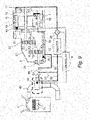
- FIG. 1 is a view for illustrating a configuration of a drive system for a vehicle according to a first embodiment of this invention.
- the drive system includes a motor 1, a gear assembly 3, an engine 4, and a controller 5.
- the gear assembly 3 is arranged on an output side of the motor 1.
- the motor 1 includes a stator 10 and a rotor 11 arranged on a radially inner side of the stator 10.
- a winding 12 is wound around the stator 10.
- the motor 1 may be, for example, a permanent-magnet electric motor including permanent magnets, a synchronous electric motor including a field winding, an induction electric motor including a cage-shaped conductor, or a reluctance motor in which a rotor includes only a rotor core. Components for causing a rotor to generate a magnetic field and shapes thereof are not limited.
- the stator 10 is fixed on an inner peripheral side of a frame 16 by, for example, shrink fit.
- the frame 16 is formed by, for example, low-pressure casting or die casting.
- a shape and dimensions of the frame 16 including a bracket for supporting bearings are not limited.
- the winding 12 is formed by distributed winding or concentrated winding.
- the winding 12 may be formed of any of a square wire or a round wire.
- a winding method and a kind of winding are not limited.
- a current and a voltage output from an inverter 2 cause a current to flow through the winding 12, and generate a rotating magnetic field.
- the rotating magnetic field rotates the rotor 11 so that the motor 1 generates torque.
- the rotor 11 is coupled to the gear assembly 3 through intermediation of a shaft 17.
- a gear output shaft 23 of the gear assembly 3 is coupled to an axle, a vehicle is driven.
- the motor 1 is not required to be a motor for drive that converts electric energy into kinetic energy for a vehicle, but may be a motor for regeneration that generates electric energy from kinetic energy for a vehicle.
- the motor 1 may also be used for both drive and regeneration.
- the motor 1 may be cooled with refrigerant such as water. At this time, it is preferred that a lubricating oil 30 be heated to a temperature higher than that of the refrigerant.
- the gear assembly 3 includes a gear box 21 and a plurality of gears 22 arranged therein.
- a gear ratio of the gears 22 is determined so as to decelerate a rotation speed of the motor 1.
- the gears 22 are parallel-axis spur gears.
- the gears 22 may be all planetary gears or a combination of a planetary gear and a spur gear. Whether the gears 22 have a parallel-axis configuration or a uniaxial configuration and a gear ratio of the gears 22 are not limited. Although illustration is omitted, in general, a differential gear is arranged between the gear assembly 3 and the axle.
- the lubricating oil 30 is stagnant in a lower part of the gear assembly 3.
- the lubricating oil 30 flows between the motor 1 and the gear assembly 3 to lubricate and cool the motor 1 and the gears 22.
- a part of the gears 22 in the gear assembly 3 is immersed in the lubricating oil 30.
- the lubricating oil 30 is diffused inside the gear assembly 3 to lubricate the gears 22.
- the engine 4 is an internal combustion engine including a cylinder and a piston provided in the cylinder.
- the engine 4 generates torque for travel and/or drives the electric motor.
- a catalytic converter 44 is provided to an exhaust pipe 43.
- Exhaust-gas purification performance of a three-way catalyst included in the catalytic converter 44 does not become effective at a low temperature, and a catalyst temperature is required to exceed 500°C.
- a temperature of an exhaust gas from the engine 4 widely ranges from about 200°C, which is a temperature during idling, to about 800°C, which is a temperature during a full-load operation.
- the purification performance of the catalyst cannot become effective at the time of cold start.
- the drive system includes oil paths for circulating the lubricating oil 30 through the gear assembly 3 and the catalytic converter 44.
- the oil paths according to this embodiment include an oil path 51 and an oil path 52.
- the oil path 51 allows the lubricating oil 30 to be introduced from the gear assembly 3 into the catalytic converter 44.
- the oil path 52 allows the lubricating oil 30 to return from the catalytic converter 44 to the motor 1. It is preferred that the oil path 52 extend downwardly from the catalytic converter 44 so that the lubricating oil 30 in the catalytic converter 44 exits under the gravity.
- a pump 59 for circulating the lubricating oil 30 is provided in the oil path 52. Details of operating conditions of the pump 59 are described later. It is preferred that the pump 59 be set to operate when a temperature of the catalytic converter 44 is lower than an oil temperature.
- the pump 59 be provided on a downstream side of the catalytic converter 44 to suck the lubricating oil 30 stagnant in the catalytic converter 44.
- the lubricating oil 30 that has been cooled in the catalytic converter 44 flows into the pump 59.
- the lubricating oil 30 having a high temperature does not flow into the pump 59, and thus the pump 59 can be driven under a small temperature load.
- the lubricating oil 30 that has returned to the motor 1 through the oil path 52 may be directly supplied to the winding 12 of the motor 1, or the lubricating oil 30 discharged through the oil path 52 may be stored inside the motor 1 to cool the winding 12.
- the winding 12 in contact with the lubricating oil 30 be configured to extend to an outside (coil end) of an outer periphery of the stator 10.
- the lubricating oil 30 that has cooled the motor 1 is warmed up with the winding 12. After that, the lubricating oil 30 passes through a connecting path between the motor 1 and the gear assembly 3 to stagnate in the lower part of the gear assembly 3.
- the lubricating oil 30 cools a coil of the motor 1, then lubricates the gears 22, and is guided to the catalytic converter 44.
- the gears 22 are lubricated with the lubricating oil 30 having a high temperature (specifically, a low viscosity). After that, the lubricating oil 30 having a high temperature supplies heat to the catalyst.
- the drive system includes three temperature sensors 61 to 63.
- the temperature sensor 61 is provided to the motor 1, and measures a temperature of the winding 12.
- the temperature sensor 62 is provided to the gear assembly 3, and measures a temperature (oil temperature) of the lubricating oil 30.
- the temperature sensor 63 is provided to the catalytic converter 44, and measures a temperature of the catalyst.
- the pump 59 is switched on and off to be operated based on the temperatures measured by the sensors 61 to 63, respectively.
- opening and closing of a valve are controlled based on the temperatures measured by the sensors 61 to 63, respectively.
- the controller 5 includes a computer (microcomputer) including an arithmetic device, a memory, and an input/output device.
- the controller 5 may be provided separately from the inverter 2 or may be provided in the inverter 2 that controls the motor 1.
- the arithmetic device includes a processor, and executes a program stored in the memory. A part of processing, which is performed through the execution of the program by the arithmetic device, may be executed by another arithmetic device (for example, hardware such as a field programmable gate array (FPGA) or an application specific integrated circuit (ASIC)).
- FPGA field programmable gate array
- ASIC application specific integrated circuit
- the memory includes a ROM and a RAM, which are non-volatile storage elements.
- the ROM stores, for example, an invariable program (such as a BIOS).
- the RAM is a high-speed volatile storage element such as a dynamic random access memory (DRAM) and a non-volatile storage element such as a static random access memory (SRAM).
- the RAM stores a program to be executed by the arithmetic device and data to be used at the time of execution of the program.
- the program to be executed by the arithmetic device is stored in a non-volatile storage device, which is a non-transitory storage medium for the controller 5.
- the input/output device is an interface that transmits a content of processing to an outside and receives data from the outside in accordance with a predetermined protocol.
- FIG. 2 to FIG. 5 are views for illustrating a configuration of the catalytic converter 44 according to this embodiment.
- the catalytic converter 44 illustrated in FIG. 2 includes a case 441.
- the case 441 contains a catalyst 442, and allows the exhaust gas to pass therethrough.
- the case 441 has a side wall having a double-layered structure.
- the catalytic converter 44 has an oil passage 443 for the lubricating oil 30 inside the case 441.
- the oil passage 443 has an inflow port 445 and an outflow port 446.
- the lubricating oil 30 flows into the inflow port 445 in an inflow direction of the exhaust gas (indicated by an arrow 440).
- the lubricating oil 30 flows out from the outflow port 446 in an outflow direction of the exhaust gas.
- An air layer 444 is defined by the case 441 and the catalyst 442.
- the air layer 444 functions as a heat insulator so as to prevent a sudden increase in temperature of the catalyst 442, which may be caused by the lubricating oil 30 having a high temperature, or an increase in temperature of the lubricating oil 30, which may be caused by the exhaust gas having a high temperature.
- a catalytic converter 44 illustrated in FIG. 3 includes a case 441.
- the case 441 contains a catalyst 442, and allows the exhaust gas to pass therethrough.
- the case 441 has a side wall having a double-layered structure.
- the catalytic converter 44 has an oil passage 443 for the lubricating oil 30 inside the case 441.
- An arrow 440 in FIG. 3 indicates the direction in which the exhaust gas flows.
- the case 441 has an inflow port 445 and an outflow port 446.
- the lubricating oil 30 flows into the case 441 in a radial direction through the inflow port 445.
- the lubricating oil 30 flows out in the radial direction through the outflow port 446.
- An air layer 444 is defined by the case 441 and the catalyst 442.
- the air layer 444 functions as a heat insulator so as to prevent a sudden increase in temperature of the catalyst 442, which may be caused by the lubricating oil 30 having a high temperature, or an increase in temperature of the lubricating oil 30, which may be caused by the exhaust gas having a high temperature.
- a catalytic converter 44 illustrated in FIG. 4 has an oil passage 443 for the lubricating oil 30.
- the oil passage 443 extends along an inner surface of a side wall of a case 441 that stores a catalyst 442 and allows the exhaust gas to pass therethrough.
- the oil passage 443 has an inflow port 445 and an outflow port 446.
- the lubricating oil 30 flows into the case 441 through the inflow port 445 in an inflow direction of the exhaust gas (indicated by an arrow 440).
- the lubricating oil 30 flows out of the case 441 through the outflow port 446 in an outflow direction of the exhaust gas.
- the catalytic converter 44 illustrated in FIG. 4 does not have an air layer. However, when the lubricating oil 30 is controlled to flow in a sufficient amount, an increase in temperature of the lubricating oil 30 can be prevented without an air layer.
- a catalytic converter 44 illustrated in FIG. 5 has an oil passage 443 having a helical structure inside a case 441.
- the oil passage 443 may be formed in an inner surface or an outer surface of the case 441.
- the oil passage 443 has an inflow port 445 and an outflow port 446 at its ends.
- the lubricating oil 30 flows into the case 441 through the inflow port 445, and flows out of the case 441 through the outflow port 446.
- the catalytic converter 44 illustrated in FIG. 5 may be with or without an air layer.
- An arrow 440 in FIG. 5 indicates a direction in which the exhaust gas flows.
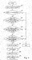
- FIG. 6 is a flowchart for illustrating an example of control on the drive system according to this embodiment.
- Step 101 When turn-on of an ignition switch is detected, control on the drive system according to this flowchart starts (Step 101).
- Step 102 determines whether or not the engine 4 is in a stop state.
- Step 102 elapsed time from the last start of the engine 4 to the achievement of sufficient warm-up of the catalyst 442 may be determined.
- the processing is terminated.
- a temperature of the catalyst 442 is equal to or lower than a predetermined threshold value (for example, 550°C) (Step 103).
- a predetermined threshold value for example, 550°C
- Step 104 it is determined whether or not the temperature of the lubricating oil 30 is equal to or higher than a predetermined threshold value (Step 104).
- the catalyst 442 cannot be warmed up.
- the determination relating to the temperature of the catalyst 442 and the determination relating to the oil temperature may be made in Step 103 and Step 104 not by comparing the temperature of the catalyst 442 and the oil temperature with the predetermined threshold values, respectively, but by first determining whether or not the temperature of the lubricating oil 30 is higher than the temperature of the catalyst 442. In this case, when the temperature of the lubricating oil 30 is higher than the temperature of the catalyst 442, the processing may proceed to Step 105.
- Step 105 it is determined whether or not the temperature of the winding 12 is equal to or higher than a predetermined threshold value.
- the winding 12 cannot warm up the lubricating oil 30, and thus cannot warm up the catalyst 442. Thus, this processing is terminated.
- the pump 59 is operated to circulate the lubricating oil 30 through the oil paths (Step 106).
- the motor 1 is cooled with the lubricating oil 30 that has been cooled in the catalytic converter 44 (Step 107).
- the gears 22 are lubricated with the lubricating oil 30 that has been warmed up in the motor 1 (Step 108).
- the lubricating oil 30 that has been warmed up in the motor 1 is circulated through the catalytic converter 44 to heat the catalyst 442 to thereby raise the temperature of the catalyst 442 (Step 109).
- the pump 59 is controlled to operate under a state in which the catalyst 442 has not been warmed up.
- the pump 59 is controlled to operate.
- the lubricating oil 30 having a high temperature, which has not been sufficiently cooled is circulated after the temperature of the catalyst 442 has risen, the temperature of the winding 12 may become higher, which may result in burnout of the winding 12.
- the temperature of the lubricating oil 30 is high, it is necessary to circulate a large amount of the lubricating oil 30 to perform control so as to lower the temperatures of the lubricating oil 30 and the winding 12.
- FIG. 7 and FIG. 8 are graphs each for showing a change in temperature of the catalyst 442 in the drive system according to this embodiment.
- the catalyst 442 when the engine 4 operates, the catalyst 442 is warmed up to 550°C or higher with the exhaust gas from the engine 4.
- the temperature of the catalyst 442 decreases. After that, when the engine 4 repeats starting and stopping, the temperature of the catalyst 442 fluctuates.
- the motor 1 when the engine 4 is in a stop state, the catalyst 442 is warmed up with heat generated from the winding 12.
- the temperature of the catalyst 442 is maintained at about 100°C.
- the pump 59 may be operated to warm up the catalyst 442. In this manner, the catalyst 442 is warmed up to prevent its temperature from decreasing to normal temperature, and is maintained at about 100°C. In this manner, time required to raise the temperature of the catalyst 442 at the time of start of the engine 4 can be shortened.
- the lubricating oil 30 in the gear assembly 3, which has been heated in the motor 1 is allowed to flow through the catalytic converter 44 to warm up the catalyst 442 and keep its temperature.
- the operation of the pump 59 is switched to circulate the lubricating oil 30 based on the temperature of the catalyst 442, the temperature of the lubricating oil 30, and the temperature of the winding 12.
- the motor 1 can be cooled without a heat exchanger for cooling the lubricating oil 30 that has been heated in the motor 1.
- time required to raise the temperature of the catalyst 442 can be shortened.
- the catalyst converter 44 is not required to be warmed up, resulting in reduced fuel consumption and power consumption.
- an electrically-driven vehicle including an internal combustion engine such as a plug-in hybrid electric vehicle (PHEV)
- PHEV plug-in hybrid electric vehicle
- the catalyst 442 can be maintained at a temperature higher than normal temperature.
- FIG. 9 is a view for illustrating a configuration of a drive system for a vehicle according to a second embodiment of this invention.
- the drive system according to the second embodiment includes a bypass oil path 53 included in oil paths and a radiator 55 provided in the oil path.
- a bypass oil path 53 included in oil paths and a radiator 55 provided in the oil path included in oil paths and a radiator 55 provided in the oil path.
- components different from those of the above-mentioned drive system according to the first embodiment are mainly described, and a description of components having the same functions as those of the drive system according to the first embodiment is omitted.
- the drive system includes a motor 1, a gear assembly 3, an engine 4, and a controller 5.
- the oil paths according to this embodiment includes an oil path 51, an oil path 52, and the bypass oil path 53.
- the oil path 51 allows a lubricating oil 30 to be introduced from the gear assembly 3 into a catalytic converter 44.
- the oil path 52 allows the lubricating oil 30 to return from the catalytic converter 44 to the motor 1.
- the bypass oil path 53 connects the oil path 51 and the oil path 52 to each other, bypassing the catalytic converter 44.
- a valve 56 is provided at a branch point at which the bypass oil path 53 branches from the oil path 51. When the valve 56 is in an open state, the lubricating oil 30 flows from the gear assembly 3 into the catalytic converter 44. When the valve 56 is in a closed state, the lubricating oil 30 flows from the gear assembly 3 into the bypass oil path 53 without flowing into the catalytic converter 44.
- the oil path 52 extend downwardly from the catalytic converter 44 so that the lubricating oil 30 in the catalytic converter 44 exits under the gravity.
- the radiator 55 for cooling the lubricating oil 30 that has been heated in the motor 1 is provided in the oil path 52.
- a pump 59 for circulating the lubricating oil 30 is provided on a downstream side of the radiator 55 in the oil path 52. As described in the first embodiment, it is preferred that the pump 59 operate when a temperature of the catalytic converter 44 is lower than an oil temperature. It is preferred that the pump 59 be provided on a downstream side of the catalytic converter 44 to suck the lubricating oil 30 stagnant in the catalytic converter 44.
- the lubricating oil 30 that has returned to the motor 1 through the oil path 52 may be directly supplied to the winding 12 of the motor 1, or the lubricating oil 30 discharged from the oil path 52 may be stored in the motor 1 to cool the winding 12. Further, it is preferred that the winding 12 in contact with the lubricating oil 30 extend to an outside (coil end) of an outer periphery of a stator 10. After the lubricating oil 30, which has cooled the motor 1, is warmed up with the winding 12, the lubricating oil 30 passes through a connecting path between the motor 1 and the gear assembly 3 to stagnate in a lower part of the gear assembly 3.
- the lubricating oil 30 lubricates the gears 22 and is then guided to the catalytic converter 44.
- the gears 22 are lubricated with the lubricating oil 30 having a high temperature (specifically, a low viscosity).
- the lubricating oil 30 having a high temperature supplies heat to a catalyst.
- the valve 56 is closed. In this manner, the lubricating oil 30 flowing from the gear assembly 3 is allowed to bypass the catalytic converter 44 and flow into the bypass oil path 53. As a result, the lubricating oil 30 is prevented from coming into contact with the catalyst 442 having a high temperature to thereby suppress degradation of the lubricating oil 30.
- the radiator 55 is provided on the downstream side of the catalytic converter 44.
- the lubricating oil 30 having a temperature increased in the motor 1 can transfer heat to the catalytic converter 44 before releasing heat in the radiator 55.
- the lubricating oil 30 that has been cooled in the catalytic converter 44 is further cooled by the radiator 55 to thereby improve cooling efficiency for the motor 1.
- the pump 59 is provided on a downstream side of the radiator 55.
- the lubricating oil 30 that has been cooled in the radiator 55 flows into the pump 59.
- the lubricating oil 30 having a high temperature does not flow into the pump 59.
- the pump 59 can be driven under a small temperature load state.
- FIG. 10 is a view for illustrating a configuration of a drive system for a vehicle according to a third embodiment of this invention.
- the drive system according to the third embodiment includes a circulation oil path 54 included in oil paths and a radiator 55 provided in the oil path.
- a circulation oil path 54 included in oil paths and a radiator 55 provided in the oil path components different from those of the above-mentioned drive systems according to the first embodiment and the second embodiment are mainly described, and a description of components having the same functions as those of the drive systems according to the first embodiment and the second embodiment is omitted.
- the oil paths according to this embodiment includes an oil path 51, an oil path 52, and the circulation oil path 54.
- the oil path 51 allows a lubricating oil 30 to be introduced from a gear assembly 3 into a catalytic converter 44.
- the oil path 52 allows the lubricating oil 30 to return from the catalytic converter 44 to the motor 1.
- the circulation oil path 54 allows the lubricating oil 30 to circulate in the radiator 55.
- a valve 57 is provided on an upstream side of the catalytic converter 44. When the valve 57 is in an open state, the lubricating oil 30 flowing from the gear assembly 3 flows into the catalytic converter 44. When the valve 57 is in a closed state, the lubricating oil 30 flowing from the gear assembly 3 does not flow into the catalytic converter 44.
- the oil path 52 extend downwardly from the catalytic converter 44 so that the lubricating oil 30 in the catalytic converter 44 exits under the gravity.
- the radiator 55 for cooling the lubricating oil 30 that has been heated in the motor 1 is provided in the oil path 52.
- a pump 59 for circulating the lubricating oil 30 is provided on a downstream side of the radiator 55 in the oil path 52. As described in the first embodiment, it is preferred that the pump 59 operate when a temperature of the catalytic converter 44 is lower than an oil temperature. It is preferred that the pump 59 be provided on a downstream side of the catalytic converter 44 to suck the lubricating oil 30 stagnant in the catalytic converter 44.
- the lubricating oil 30 that has returned to the motor 1 through the oil path 52 may be directly supplied to the winding 12 of the motor 1, or the lubricating oil 30 discharged from the oil path 52 may be stored in the motor 1 to cool the winding 12. Further, it is preferred that the winding 12 in contact with the lubricating oil 30 extend to an outside (coil end) of an outer periphery of a stator 10. After the lubricating oil 30, which has returned to the motor 1, is warmed up with the winding 12, the lubricating oil 30 passes through a connecting path between the motor 1 and the gear assembly 3 to stagnate in a lower part of the gear assembly 3.
- the circulation oil path 54 is formed so as to bring a part of the oil path 52, which is in the vicinity of an outlet of the catalytic converter 44 for the lubricating oil 30, and an outlet of the radiator 55 for the lubricating oil 30 into with each other.
- a valve 58 is provided in the middle of the circulation oil path 54.
- a circulation pump may be provided in the middle of the circulation oil path 54.
- the valve 57 is opened and the valve 58 is closed.
- the lubricating oil 30 is circulated through the catalytic converter 44 and the radiator 55 to thereby cool the lubricating oil 30 that has been heated in the motor 1.
- the lubricating oil 30 lubricates the gears 22 and is then guided to the catalytic converter 44.
- the gears 22 are lubricated with the lubricating oil 30 having a high temperature (specifically, a low viscosity).
- the lubricating oil 30 having a high temperature supplies heat to a catalyst.
- the catalytic converter 44 has a high temperature
- the lubricating oil 30 is circulated through the radiator 55 via the circulation oil path 54. In this manner, the lubricating oil 30 is efficiently cooled to thereby suppress the degradation of the lubricating oil 30.
- the radiator 55 is provided on the downstream side of the catalytic converter 44.
- the lubricating oil 30 having a temperature increased in the motor 1 can transfer heat to the catalytic converter 44 before releasing heat in the radiator 55.
- the lubricating oil 30 that has been cooled in the catalytic converter 44 is further cooled by the radiator 55 to thereby improve cooling efficiency for the motor 1.
- the pump 59 is provided on a downstream side of the radiator 55.
- the lubricating oil 30 that has been cooled in the radiator 55 flows into the pump 59.
- the lubricating oil 30 having a high temperature does not flow into the pump 59.
- the pump 59 can be driven under a small temperature load state.
- the drive system includes the internal combustion engine (engine 4), the catalytic unit (catalytic converter 44) that purifies the exhaust gas from the internal combustion engine, the motor 1 used for at least one of drive or regeneration, and the flow paths (oil paths 51, 52 and 53) formed so as to allow the oil-based medium (lubricating oil 30) for lubricating the motor 1 to flow in the vicinity of the catalytic unit (catalyst 442).
- the oil-based medium 30 is heated in the motor 1, and exchanges heat in the catalytic converter 44 to thereby heat the catalyst 442.
- the use of the oil-based medium 30 that can have a temperature higher than a temperature of water improves warm-up efficiency for the catalytic converter 44, and the catalytic converter 44 can be more quickly warmed up to a high temperature and start keeping its temperature earlier in comparison to a case in which a catalytic converter is warmed up with cooling water to a temperature falling within a range of from 65°C to 90°C and keeps its temperature.
- a fuel consumption for warming up the catalytic converter 44 and keeping its temperature can be reduced.
- the drive system includes the gear assembly 3 that transmits the output from the motor 1 via the gears 22, and uses the lubricating oil 30 for lubricating the gears 22 as the oil-based medium.
- a transmission oil is circulated through the catalytic converter 44 to thereby warm up the catalytic converter 44 and raise the temperature of the catalytic converter 44.
- the lubricating oil 30 is supplied to the transmission and is then introduced into the catalytic converter 44.
- the lubricating oil 30 is maintained at a high temperature to thereby warm up the catalytic converter 44.
- the gear assembly 3 can be lubricated with the lubricating oil 30 having a high temperature and a low viscosity.
- lubrication resistance of the gear assembly 3 can be reduced.
- the oil-based medium 30 is heated by cooling the winding 12 of the motor 1 through contact with the winding 12.
- raising the temperature of the oil-based medium 30 allows heat to be used to warm up the catalyst 442 after the lubrication resistance of the gear assembly 3 is reduced.
- the motor 1 is cooled with the refrigerant, and the oil-based medium 30 is heated to a temperature higher than a temperature of the refrigerant.
- the use of the oil-based medium 30 allows the catalytic converter 44 to be warmed up to a high temperature and its temperature to be kept.
- the drive system includes the valves 56 and 57 that control the oil-based medium 30 so as to prevent the oil-based medium 30 from flowing in the vicinity of the catalyst 442 when the temperature of the catalyst 442 is higher than the predetermined threshold value.
- the temperature of the lubricating oil 30 is not increased to a high temperature. As a result, the degradation of the lubricating oil 30 can be prevented.
- the drive system includes the pump 59 that allows the oil-based medium 30 to circulate.
- the pump 59 is controlled so as to prevent the oil-based medium 30 from flowing in the vicinity of the catalyst 442.
- the information of programs, tables, and files to implement the functions may be stored in a storage device such as a memory, a hard disk drive, or an SSD (a Solid State Drive), or a storage medium such as an IC card, or an SD card.
- a storage device such as a memory, a hard disk drive, or an SSD (a Solid State Drive), or a storage medium such as an IC card, or an SD card.
Landscapes
- Engineering & Computer Science (AREA)
- Chemical & Material Sciences (AREA)
- Combustion & Propulsion (AREA)
- Mechanical Engineering (AREA)
- Chemical Kinetics & Catalysis (AREA)
- General Engineering & Computer Science (AREA)
- Transportation (AREA)
- Power Engineering (AREA)
- Health & Medical Sciences (AREA)
- Toxicology (AREA)
- Automation & Control Theory (AREA)
- Exhaust Gas After Treatment (AREA)
- Cooling, Air Intake And Gas Exhaust, And Fuel Tank Arrangements In Propulsion Units (AREA)
- Hybrid Electric Vehicles (AREA)
Abstract
Description
- This invention relates to a drive system, and more particularly, to a drive system including a motor and an engine.
- A vehicle including an engine warms up a three-way catalyst with a high-temperature exhaust gas emitted from the engine. Meanwhile, a vehicle including an engine and a motor, such as a hybrid vehicle, less frequently uses the engine to travel, and thus cannot sufficiently warm up the three-way catalyst with an exhaust gas. As a result, a temperature of the catalyst may decrease to lower exhaust-gas purification performance.
- Examples of the background art of this technical field include Patent Literature 1 (
JP H6-276614A Patent Literature 1, there is described a drive apparatus for a hybrid vehicle, which includes a power generator, a battery, an electric motor, a power conversion controller, a heating means, a temperature detecting means, and a refrigerant flow-path switching means. The power generator is rotationally driven by an engine to generate electric power. The battery converts an output from the power generator into DC power, and stores the DC power. The electric motor generates a driving force by using the power generator and the battery as power sources. The power conversion controller controls the electric motor. The heating means collects heat generated in the power conversion controller and the electric motor, and heats an engine-associated component. The temperature detecting means detects a temperature of the engine-associated component. The refrigerant flow-path switching means switches a flow path for refrigerant being the heating means based on the temperature detected by the temperature detecting means. - Further, in Patent Literature 2 (
JP 2017-227163A - Still further, in Patent Literature 3 (
JP2000-265910A - In the above-mentioned related art, cooling water for the engine is used to warm up the catalyst. Thus, the cooling water has a low temperature, and is given at merely about 65°C to 90°C. As a result, a temperature of the catalyst does not sufficiently rise, providing only small effects of warming up the catalyst and keeping its temperature. Thus, a drive system capable of more efficiently warming up the catalyst and keeping its temperature is desired.
- A representative one of the invention disclosed in this application is outlined as follows. There is provided a drive system including: an internal combustion engine; a catalytic unit configured to purify an exhaust gas from the internal combustion engine; a motor used for at least one of drive or regeneration; and a flow path formed so as to allow an oil-based medium for lubricating the motor to flow in the vicinity of the catalytic unit, wherein the oil-based medium is heated in the motor and exchanges heat in the catalytic unit to heat the catalytic unit.
- According to one aspect of this invention, fuel consumption for warming up the catalyst and keeping its temperature can be reduced. Problems, configurations, and effects other than those described above become apparent through the following description of embodiments.
-
-
FIG. 1 is a view for illustrating a configuration of a drive system for a vehicle according to a first embodiment of this invention. -
FIG. 2 is a view for illustrating a configuration of the catalytic converter according to this embodiment. -
FIG. 3 is a view for illustrating a configuration of the catalytic converter according to this embodiment. -
FIG. 4 is a view for illustrating a configuration of the catalytic converter according to this embodiment. -
FIG. 5 is a view for illustrating a configuration of the catalytic converter according to this embodiment. -
FIG. 6 is a flowchart for illustrating an example of control on the drive system according to this embodiment. -
FIG. 7 is a graph for showing a change in temperature of the catalyst in the drive system according to this embodiment. -
FIG. 8 is a graph for showing a change in temperature of the catalyst in the drive system according to this embodiment. -
FIG. 9 is a view for illustrating a configuration of a drive system for a vehicle according to a second embodiment of this invention. -
FIG. 10 is a view for illustrating a configuration of a drive system for a vehicle according to a third embodiment of this invention. -
FIG. 1 is a view for illustrating a configuration of a drive system for a vehicle according to a first embodiment of this invention. - The drive system according to this embodiment includes a
motor 1, agear assembly 3, anengine 4, and acontroller 5. Thegear assembly 3 is arranged on an output side of themotor 1. - The
motor 1 includes astator 10 and arotor 11 arranged on a radially inner side of thestator 10. A winding 12 is wound around thestator 10. Themotor 1 may be, for example, a permanent-magnet electric motor including permanent magnets, a synchronous electric motor including a field winding, an induction electric motor including a cage-shaped conductor, or a reluctance motor in which a rotor includes only a rotor core. Components for causing a rotor to generate a magnetic field and shapes thereof are not limited. Thestator 10 is fixed on an inner peripheral side of aframe 16 by, for example, shrink fit. Theframe 16 is formed by, for example, low-pressure casting or die casting. A shape and dimensions of theframe 16 including a bracket for supporting bearings are not limited. The winding 12 is formed by distributed winding or concentrated winding. The winding 12 may be formed of any of a square wire or a round wire. A winding method and a kind of winding are not limited. - A current and a voltage output from an
inverter 2 cause a current to flow through the winding 12, and generate a rotating magnetic field. The rotating magnetic field rotates therotor 11 so that themotor 1 generates torque. Therotor 11 is coupled to thegear assembly 3 through intermediation of ashaft 17. When agear output shaft 23 of thegear assembly 3 is coupled to an axle, a vehicle is driven. Further, themotor 1 is not required to be a motor for drive that converts electric energy into kinetic energy for a vehicle, but may be a motor for regeneration that generates electric energy from kinetic energy for a vehicle. Themotor 1 may also be used for both drive and regeneration. Further, themotor 1 may be cooled with refrigerant such as water. At this time, it is preferred that a lubricatingoil 30 be heated to a temperature higher than that of the refrigerant. - The
gear assembly 3 includes agear box 21 and a plurality ofgears 22 arranged therein. A gear ratio of thegears 22 is determined so as to decelerate a rotation speed of themotor 1. InFIG. 1 , thegears 22 are parallel-axis spur gears. However, thegears 22 may be all planetary gears or a combination of a planetary gear and a spur gear. Whether thegears 22 have a parallel-axis configuration or a uniaxial configuration and a gear ratio of thegears 22 are not limited. Although illustration is omitted, in general, a differential gear is arranged between thegear assembly 3 and the axle. - As illustrated with small dots in
FIG. 1 , the lubricatingoil 30 is stagnant in a lower part of thegear assembly 3. The lubricatingoil 30 flows between themotor 1 and thegear assembly 3 to lubricate and cool themotor 1 and thegears 22. A part of thegears 22 in thegear assembly 3 is immersed in the lubricatingoil 30. Along with the rotation of thegears 22, the lubricatingoil 30 is diffused inside thegear assembly 3 to lubricate thegears 22. - The
engine 4 is an internal combustion engine including a cylinder and a piston provided in the cylinder. Theengine 4 generates torque for travel and/or drives the electric motor. Acatalytic converter 44 is provided to anexhaust pipe 43. Exhaust-gas purification performance of a three-way catalyst included in thecatalytic converter 44 does not become effective at a low temperature, and a catalyst temperature is required to exceed 500°C. Meanwhile, a temperature of an exhaust gas from theengine 4 widely ranges from about 200°C, which is a temperature during idling, to about 800°C, which is a temperature during a full-load operation. Thus, the purification performance of the catalyst cannot become effective at the time of cold start. - Thus, the drive system according to this embodiment includes oil paths for circulating the lubricating
oil 30 through thegear assembly 3 and thecatalytic converter 44. - The oil paths according to this embodiment include an
oil path 51 and anoil path 52. Theoil path 51 allows the lubricatingoil 30 to be introduced from thegear assembly 3 into thecatalytic converter 44. Theoil path 52 allows the lubricatingoil 30 to return from thecatalytic converter 44 to themotor 1. It is preferred that theoil path 52 extend downwardly from thecatalytic converter 44 so that the lubricatingoil 30 in thecatalytic converter 44 exits under the gravity. Apump 59 for circulating the lubricatingoil 30 is provided in theoil path 52. Details of operating conditions of thepump 59 are described later. It is preferred that thepump 59 be set to operate when a temperature of thecatalytic converter 44 is lower than an oil temperature. It is preferred that thepump 59 be provided on a downstream side of thecatalytic converter 44 to suck the lubricatingoil 30 stagnant in thecatalytic converter 44. The lubricatingoil 30 that has been cooled in thecatalytic converter 44 flows into thepump 59. Thus, the lubricatingoil 30 having a high temperature does not flow into thepump 59, and thus thepump 59 can be driven under a small temperature load. The lubricatingoil 30 that has returned to themotor 1 through theoil path 52 may be directly supplied to the winding 12 of themotor 1, or the lubricatingoil 30 discharged through theoil path 52 may be stored inside themotor 1 to cool the winding 12. Further, it is preferred that the winding 12 in contact with the lubricatingoil 30 be configured to extend to an outside (coil end) of an outer periphery of thestator 10. The lubricatingoil 30 that has cooled themotor 1 is warmed up with the winding 12. After that, the lubricatingoil 30 passes through a connecting path between themotor 1 and thegear assembly 3 to stagnate in the lower part of thegear assembly 3. - In this embodiment, the lubricating
oil 30 cools a coil of themotor 1, then lubricates thegears 22, and is guided to thecatalytic converter 44. Thus, thegears 22 are lubricated with the lubricatingoil 30 having a high temperature (specifically, a low viscosity). After that, the lubricatingoil 30 having a high temperature supplies heat to the catalyst. - The drive system according to this embodiment includes three
temperature sensors 61 to 63. Thetemperature sensor 61 is provided to themotor 1, and measures a temperature of the winding 12. Thetemperature sensor 62 is provided to thegear assembly 3, and measures a temperature (oil temperature) of the lubricatingoil 30. Thetemperature sensor 63 is provided to thecatalytic converter 44, and measures a temperature of the catalyst. In this embodiment, thepump 59 is switched on and off to be operated based on the temperatures measured by thesensors 61 to 63, respectively. In another embodiment to be described later, in addition to on and off of thepump 59, opening and closing of a valve are controlled based on the temperatures measured by thesensors 61 to 63, respectively. - The
controller 5 includes a computer (microcomputer) including an arithmetic device, a memory, and an input/output device. Thecontroller 5 may be provided separately from theinverter 2 or may be provided in theinverter 2 that controls themotor 1. - The arithmetic device includes a processor, and executes a program stored in the memory. A part of processing, which is performed through the execution of the program by the arithmetic device, may be executed by another arithmetic device (for example, hardware such as a field programmable gate array (FPGA) or an application specific integrated circuit (ASIC)).
- The memory includes a ROM and a RAM, which are non-volatile storage elements. The ROM stores, for example, an invariable program (such as a BIOS). The RAM is a high-speed volatile storage element such as a dynamic random access memory (DRAM) and a non-volatile storage element such as a static random access memory (SRAM). The RAM stores a program to be executed by the arithmetic device and data to be used at the time of execution of the program. The program to be executed by the arithmetic device is stored in a non-volatile storage device, which is a non-transitory storage medium for the
controller 5. - The input/output device is an interface that transmits a content of processing to an outside and receives data from the outside in accordance with a predetermined protocol.
-
FIG. 2 to FIG. 5 are views for illustrating a configuration of thecatalytic converter 44 according to this embodiment. - The
catalytic converter 44 illustrated inFIG. 2 includes acase 441. Thecase 441 contains acatalyst 442, and allows the exhaust gas to pass therethrough. Thecase 441 has a side wall having a double-layered structure. Thecatalytic converter 44 has anoil passage 443 for the lubricatingoil 30 inside thecase 441. Theoil passage 443 has aninflow port 445 and anoutflow port 446. The lubricatingoil 30 flows into theinflow port 445 in an inflow direction of the exhaust gas (indicated by an arrow 440). The lubricatingoil 30 flows out from theoutflow port 446 in an outflow direction of the exhaust gas. Anair layer 444 is defined by thecase 441 and thecatalyst 442. Theair layer 444 functions as a heat insulator so as to prevent a sudden increase in temperature of thecatalyst 442, which may be caused by the lubricatingoil 30 having a high temperature, or an increase in temperature of the lubricatingoil 30, which may be caused by the exhaust gas having a high temperature. - A
catalytic converter 44 illustrated inFIG. 3 includes acase 441. Thecase 441 contains acatalyst 442, and allows the exhaust gas to pass therethrough. Thecase 441 has a side wall having a double-layered structure. Thecatalytic converter 44 has anoil passage 443 for the lubricatingoil 30 inside thecase 441. Anarrow 440 inFIG. 3 indicates the direction in which the exhaust gas flows. Thecase 441 has aninflow port 445 and anoutflow port 446. The lubricatingoil 30 flows into thecase 441 in a radial direction through theinflow port 445. The lubricatingoil 30 flows out in the radial direction through theoutflow port 446. Anair layer 444 is defined by thecase 441 and thecatalyst 442. Theair layer 444 functions as a heat insulator so as to prevent a sudden increase in temperature of thecatalyst 442, which may be caused by the lubricatingoil 30 having a high temperature, or an increase in temperature of the lubricatingoil 30, which may be caused by the exhaust gas having a high temperature. - A
catalytic converter 44 illustrated inFIG. 4 has anoil passage 443 for the lubricatingoil 30. Theoil passage 443 extends along an inner surface of a side wall of acase 441 that stores acatalyst 442 and allows the exhaust gas to pass therethrough. Theoil passage 443 has aninflow port 445 and anoutflow port 446. The lubricatingoil 30 flows into thecase 441 through theinflow port 445 in an inflow direction of the exhaust gas (indicated by an arrow 440). The lubricatingoil 30 flows out of thecase 441 through theoutflow port 446 in an outflow direction of the exhaust gas. Thecatalytic converter 44 illustrated inFIG. 4 does not have an air layer. However, when the lubricatingoil 30 is controlled to flow in a sufficient amount, an increase in temperature of the lubricatingoil 30 can be prevented without an air layer. - A
catalytic converter 44 illustrated inFIG. 5 has anoil passage 443 having a helical structure inside acase 441. Theoil passage 443 may be formed in an inner surface or an outer surface of thecase 441. Theoil passage 443 has aninflow port 445 and anoutflow port 446 at its ends. The lubricatingoil 30 flows into thecase 441 through theinflow port 445, and flows out of thecase 441 through theoutflow port 446. Thecatalytic converter 44 illustrated inFIG. 5 may be with or without an air layer. Anarrow 440 inFIG. 5 indicates a direction in which the exhaust gas flows. -
FIG. 6 is a flowchart for illustrating an example of control on the drive system according to this embodiment. - When turn-on of an ignition switch is detected, control on the drive system according to this flowchart starts (Step 101).
- After that, the
controller 5 determines whether or not theengine 4 is in a stop state (Step 102). InStep 102, elapsed time from the last start of theengine 4 to the achievement of sufficient warm-up of thecatalyst 442 may be determined. When theengine 4 is operating, it is assumed that thecatalyst 442 has been warmed up with the exhaust gas. Thus, the processing is terminated. - Meanwhile, when the
engine 4 is in a stop state, it is assumed that thecatalyst 442 is cold. Thus, it is determined whether or not a temperature of thecatalyst 442 is equal to or lower than a predetermined threshold value (for example, 550°C) (Step 103). When the temperature of thecatalyst 442 is higher than the predetermined threshold value, thecatalyst 442 is not required to be warmed up. Thus, this processing is terminated. - Meanwhile, when the temperature of the
catalyst 442 is equal to or lower than the predetermined threshold value, thecatalyst 442 is required to be warmed up. Thus, it is determined whether or not the temperature of the lubricatingoil 30 is equal to or higher than a predetermined threshold value (Step 104). When the temperature of the lubricatingoil 30 is lower than the predetermined threshold value, thecatalyst 442 cannot be warmed up. Thus, this processing is terminated. The determination relating to the temperature of thecatalyst 442 and the determination relating to the oil temperature may be made inStep 103 andStep 104 not by comparing the temperature of thecatalyst 442 and the oil temperature with the predetermined threshold values, respectively, but by first determining whether or not the temperature of the lubricatingoil 30 is higher than the temperature of thecatalyst 442. In this case, when the temperature of the lubricatingoil 30 is higher than the temperature of thecatalyst 442, the processing may proceed to Step 105. - Meanwhile, when the temperature of the lubricating
oil 30 is higher than the predetermined threshold value, the lubricatingoil 30 can warm up thecatalyst 442. Thus, it is determined whether or not the temperature of the winding 12 is equal to or higher than a predetermined threshold value (Step 105). When the temperature of the winding 12 is lower than the predetermined threshold value, the winding 12 cannot warm up the lubricatingoil 30, and thus cannot warm up thecatalyst 442. Thus, this processing is terminated. - Meanwhile, when the temperature of the winding 12 is equal to or higher than the predetermined threshold value, the winding 12 can warm up the lubricating
oil 30. Thus, thepump 59 is operated to circulate the lubricatingoil 30 through the oil paths (Step 106). Themotor 1 is cooled with the lubricatingoil 30 that has been cooled in the catalytic converter 44 (Step 107). Thegears 22 are lubricated with the lubricatingoil 30 that has been warmed up in the motor 1 (Step 108). The lubricatingoil 30 that has been warmed up in themotor 1 is circulated through thecatalytic converter 44 to heat thecatalyst 442 to thereby raise the temperature of the catalyst 442 (Step 109). - Specifically, the
pump 59 is controlled to operate under a state in which thecatalyst 442 has not been warmed up. When thecatalyst 442 has been warmed up and the coil temperature is sufficiently high for warming up thecatalyst 442, thepump 59 is controlled to operate. When the lubricatingoil 30 having a high temperature, which has not been sufficiently cooled, is circulated after the temperature of thecatalyst 442 has risen, the temperature of the winding 12 may become higher, which may result in burnout of the winding 12. Thus, when the temperature of the lubricatingoil 30 is high, it is necessary to circulate a large amount of the lubricatingoil 30 to perform control so as to lower the temperatures of the lubricatingoil 30 and the winding 12. -
FIG. 7 and FIG. 8 are graphs each for showing a change in temperature of thecatalyst 442 in the drive system according to this embodiment. - As shown in
FIG. 7 , when theengine 4 operates, thecatalyst 442 is warmed up to 550°C or higher with the exhaust gas from theengine 4. When theengine 4 stops, the temperature of thecatalyst 442 decreases. After that, when theengine 4 repeats starting and stopping, the temperature of thecatalyst 442 fluctuates. In this embodiment, however, when themotor 1 operates while theengine 4 is in a stop state, thecatalyst 442 is warmed up with heat generated from the winding 12. Thus, the temperature of thecatalyst 442 is maintained at about 100°C. Hence, in comparison to related-art control for a temperature of a catalyst, which is indicated by a broken line, time required to raise the temperature of thecatalyst 442 at the time of start of theengine 4 can be shortened. - Further, as shown in
FIG. 8 , when theengine 4 stops and the temperature of thecatalyst 442 drops to a predetermined threshold value (circulation determination temperature), thepump 59 may be operated to warm up thecatalyst 442. In this manner, thecatalyst 442 is warmed up to prevent its temperature from decreasing to normal temperature, and is maintained at about 100°C. In this manner, time required to raise the temperature of thecatalyst 442 at the time of start of theengine 4 can be shortened. - As described above, in the first embodiment, when the vehicle travels in an electric vehicle (EV) mode for a long period of time (while the
engine 4 is in a stop state), the lubricatingoil 30 in thegear assembly 3, which has been heated in themotor 1, is allowed to flow through thecatalytic converter 44 to warm up thecatalyst 442 and keep its temperature. Thus, the operation of thepump 59 is switched to circulate the lubricatingoil 30 based on the temperature of thecatalyst 442, the temperature of the lubricatingoil 30, and the temperature of the winding 12. Further, themotor 1 can be cooled without a heat exchanger for cooling the lubricatingoil 30 that has been heated in themotor 1. - Further, time required to raise the temperature of the
catalyst 442 can be shortened. Thus, thecatalyst converter 44 is not required to be warmed up, resulting in reduced fuel consumption and power consumption. In particular, in a case of an electrically-driven vehicle including an internal combustion engine, such as a plug-in hybrid electric vehicle (PHEV), when the internal combustion engine is in a stop state for a long period of time, an effect of raising the temperature of thecatalyst 442 with the exhaust gas cannot be obtained, resulting in a decrease in temperature of thecatalyst 442. In this embodiment, however, even when theengine 4 is in a stop state for a long period of time or is frequently stopped, thecatalyst 442 can be maintained at a temperature higher than normal temperature. -
FIG. 9 is a view for illustrating a configuration of a drive system for a vehicle according to a second embodiment of this invention. - The drive system according to the second embodiment includes a
bypass oil path 53 included in oil paths and aradiator 55 provided in the oil path. In the second embodiment, components different from those of the above-mentioned drive system according to the first embodiment are mainly described, and a description of components having the same functions as those of the drive system according to the first embodiment is omitted. - The drive system according to this embodiment includes a
motor 1, agear assembly 3, anengine 4, and acontroller 5. - The oil paths according to this embodiment includes an
oil path 51, anoil path 52, and thebypass oil path 53. Theoil path 51 allows a lubricatingoil 30 to be introduced from thegear assembly 3 into acatalytic converter 44. Theoil path 52 allows the lubricatingoil 30 to return from thecatalytic converter 44 to themotor 1. Thebypass oil path 53 connects theoil path 51 and theoil path 52 to each other, bypassing thecatalytic converter 44. Avalve 56 is provided at a branch point at which thebypass oil path 53 branches from theoil path 51. When thevalve 56 is in an open state, the lubricatingoil 30 flows from thegear assembly 3 into thecatalytic converter 44. When thevalve 56 is in a closed state, the lubricatingoil 30 flows from thegear assembly 3 into thebypass oil path 53 without flowing into thecatalytic converter 44. - It is preferred that the
oil path 52 extend downwardly from thecatalytic converter 44 so that the lubricatingoil 30 in thecatalytic converter 44 exits under the gravity. Theradiator 55 for cooling the lubricatingoil 30 that has been heated in themotor 1 is provided in theoil path 52. Further, apump 59 for circulating the lubricatingoil 30 is provided on a downstream side of theradiator 55 in theoil path 52. As described in the first embodiment, it is preferred that thepump 59 operate when a temperature of thecatalytic converter 44 is lower than an oil temperature. It is preferred that thepump 59 be provided on a downstream side of thecatalytic converter 44 to suck the lubricatingoil 30 stagnant in thecatalytic converter 44. The lubricatingoil 30 that has returned to themotor 1 through theoil path 52 may be directly supplied to the winding 12 of themotor 1, or the lubricatingoil 30 discharged from theoil path 52 may be stored in themotor 1 to cool the winding 12. Further, it is preferred that the winding 12 in contact with the lubricatingoil 30 extend to an outside (coil end) of an outer periphery of astator 10. After the lubricatingoil 30, which has cooled themotor 1, is warmed up with the winding 12, the lubricatingoil 30 passes through a connecting path between themotor 1 and thegear assembly 3 to stagnate in a lower part of thegear assembly 3. - In this embodiment, after cooling a coil of the
motor 1, the lubricatingoil 30 lubricates thegears 22 and is then guided to thecatalytic converter 44. Thus, thegears 22 are lubricated with the lubricatingoil 30 having a high temperature (specifically, a low viscosity). After that, the lubricatingoil 30 having a high temperature supplies heat to a catalyst. Further, when the temperature of thecatalytic converter 44 becomes higher, thevalve 56 is closed. In this manner, the lubricatingoil 30 flowing from thegear assembly 3 is allowed to bypass thecatalytic converter 44 and flow into thebypass oil path 53. As a result, the lubricatingoil 30 is prevented from coming into contact with thecatalyst 442 having a high temperature to thereby suppress degradation of the lubricatingoil 30. - Further, the
radiator 55 is provided on the downstream side of thecatalytic converter 44. Thus, the lubricatingoil 30 having a temperature increased in themotor 1 can transfer heat to thecatalytic converter 44 before releasing heat in theradiator 55. Further, the lubricatingoil 30 that has been cooled in thecatalytic converter 44 is further cooled by theradiator 55 to thereby improve cooling efficiency for themotor 1. - Still further, the
pump 59 is provided on a downstream side of theradiator 55. Thus, the lubricatingoil 30 that has been cooled in theradiator 55 flows into thepump 59. Thus, the lubricatingoil 30 having a high temperature does not flow into thepump 59. As a result, thepump 59 can be driven under a small temperature load state. -
FIG. 10 is a view for illustrating a configuration of a drive system for a vehicle according to a third embodiment of this invention. - The drive system according to the third embodiment includes a
circulation oil path 54 included in oil paths and aradiator 55 provided in the oil path. In the third embodiment, components different from those of the above-mentioned drive systems according to the first embodiment and the second embodiment are mainly described, and a description of components having the same functions as those of the drive systems according to the first embodiment and the second embodiment is omitted. - The oil paths according to this embodiment includes an
oil path 51, anoil path 52, and thecirculation oil path 54. Theoil path 51 allows a lubricatingoil 30 to be introduced from agear assembly 3 into acatalytic converter 44. Theoil path 52 allows the lubricatingoil 30 to return from thecatalytic converter 44 to themotor 1. Thecirculation oil path 54 allows the lubricatingoil 30 to circulate in theradiator 55. Avalve 57 is provided on an upstream side of thecatalytic converter 44. When thevalve 57 is in an open state, the lubricatingoil 30 flowing from thegear assembly 3 flows into thecatalytic converter 44. When thevalve 57 is in a closed state, the lubricatingoil 30 flowing from thegear assembly 3 does not flow into thecatalytic converter 44. - It is preferred that the
oil path 52 extend downwardly from thecatalytic converter 44 so that the lubricatingoil 30 in thecatalytic converter 44 exits under the gravity. Theradiator 55 for cooling the lubricatingoil 30 that has been heated in themotor 1 is provided in theoil path 52. Further, apump 59 for circulating the lubricatingoil 30 is provided on a downstream side of theradiator 55 in theoil path 52. As described in the first embodiment, it is preferred that thepump 59 operate when a temperature of thecatalytic converter 44 is lower than an oil temperature. It is preferred that thepump 59 be provided on a downstream side of thecatalytic converter 44 to suck the lubricatingoil 30 stagnant in thecatalytic converter 44. The lubricatingoil 30 that has returned to themotor 1 through theoil path 52 may be directly supplied to the winding 12 of themotor 1, or the lubricatingoil 30 discharged from theoil path 52 may be stored in themotor 1 to cool the winding 12. Further, it is preferred that the winding 12 in contact with the lubricatingoil 30 extend to an outside (coil end) of an outer periphery of astator 10. After the lubricatingoil 30, which has returned to themotor 1, is warmed up with the winding 12, the lubricatingoil 30 passes through a connecting path between themotor 1 and thegear assembly 3 to stagnate in a lower part of thegear assembly 3. - The
circulation oil path 54 is formed so as to bring a part of theoil path 52, which is in the vicinity of an outlet of thecatalytic converter 44 for the lubricatingoil 30, and an outlet of theradiator 55 for the lubricatingoil 30 into with each other. Avalve 58 is provided in the middle of thecirculation oil path 54. A circulation pump may be provided in the middle of thecirculation oil path 54. When the lubricatingoil 30 is to be normally circulated, thevalve 58 is closed. Meanwhile, when thecatalytic converter 44 has a high temperature and the lubricatingoil 30 has a high temperature, thevalve 57 is closed and thevalve 58 is opened. As a result, the lubricatingoil 30 having a high temperature can be efficiently cooled in theradiator 55. Meanwhile, when the temperature of the lubricatingoil 30 decreases, thevalve 57 is opened and thevalve 58 is closed. As a result, the lubricatingoil 30 is circulated through thecatalytic converter 44 and theradiator 55 to thereby cool the lubricatingoil 30 that has been heated in themotor 1. - In this embodiment, after cooling a coil of the
motor 1, the lubricatingoil 30 lubricates thegears 22 and is then guided to thecatalytic converter 44. Thus, thegears 22 are lubricated with the lubricatingoil 30 having a high temperature (specifically, a low viscosity). After that, the lubricatingoil 30 having a high temperature supplies heat to a catalyst. When thecatalytic converter 44 has a high temperature, the lubricatingoil 30 is circulated through theradiator 55 via thecirculation oil path 54. In this manner, the lubricatingoil 30 is efficiently cooled to thereby suppress the degradation of the lubricatingoil 30. - Further, the
radiator 55 is provided on the downstream side of thecatalytic converter 44. Thus, the lubricatingoil 30 having a temperature increased in themotor 1 can transfer heat to thecatalytic converter 44 before releasing heat in theradiator 55. Further, the lubricatingoil 30 that has been cooled in thecatalytic converter 44 is further cooled by theradiator 55 to thereby improve cooling efficiency for themotor 1. - Still further, the
pump 59 is provided on a downstream side of theradiator 55. Thus, the lubricatingoil 30 that has been cooled in theradiator 55 flows into thepump 59. Thus, the lubricatingoil 30 having a high temperature does not flow into thepump 59. As a result, thepump 59 can be driven under a small temperature load state. - As described above, the drive system according to the embodiments of this invention includes the internal combustion engine (engine 4), the catalytic unit (catalytic converter 44) that purifies the exhaust gas from the internal combustion engine, the
motor 1 used for at least one of drive or regeneration, and the flow paths (oil paths motor 1 to flow in the vicinity of the catalytic unit (catalyst 442). The oil-basedmedium 30 is heated in themotor 1, and exchanges heat in thecatalytic converter 44 to thereby heat thecatalyst 442. Thus, the use of the oil-basedmedium 30 that can have a temperature higher than a temperature of water improves warm-up efficiency for thecatalytic converter 44, and thecatalytic converter 44 can be more quickly warmed up to a high temperature and start keeping its temperature earlier in comparison to a case in which a catalytic converter is warmed up with cooling water to a temperature falling within a range of from 65°C to 90°C and keeps its temperature. A fuel consumption for warming up thecatalytic converter 44 and keeping its temperature can be reduced. - Further, the drive system includes the
gear assembly 3 that transmits the output from themotor 1 via thegears 22, and uses the lubricatingoil 30 for lubricating thegears 22 as the oil-based medium. Specifically, a transmission oil is circulated through thecatalytic converter 44 to thereby warm up thecatalytic converter 44 and raise the temperature of thecatalytic converter 44. After cooling the winding 12 of themotor 1, the lubricatingoil 30 is supplied to the transmission and is then introduced into thecatalytic converter 44. Thus, the lubricatingoil 30 is maintained at a high temperature to thereby warm up thecatalytic converter 44. In comparison to a case in which the lubricatingoil 30 is directly introduced from themotor 1 into thecatalytic converter 44, thegear assembly 3 can be lubricated with the lubricatingoil 30 having a high temperature and a low viscosity. Thus, lubrication resistance of thegear assembly 3 can be reduced. - Still further, the oil-based
medium 30 is heated by cooling the winding 12 of themotor 1 through contact with the winding 12. Thus, raising the temperature of the oil-basedmedium 30 allows heat to be used to warm up thecatalyst 442 after the lubrication resistance of thegear assembly 3 is reduced. - Still further, the
motor 1 is cooled with the refrigerant, and the oil-basedmedium 30 is heated to a temperature higher than a temperature of the refrigerant. Thus, in comparison to a case in which thecatalytic converter 44 is warmed up with cooling water, the use of the oil-basedmedium 30 allows thecatalytic converter 44 to be warmed up to a high temperature and its temperature to be kept. - Still further, the drive system includes the
valves medium 30 so as to prevent the oil-based medium 30 from flowing in the vicinity of thecatalyst 442 when the temperature of thecatalyst 442 is higher than the predetermined threshold value. Thus, when warm-up is not needed, the temperature of the lubricatingoil 30 is not increased to a high temperature. As a result, the degradation of the lubricatingoil 30 can be prevented. - Still further, the drive system includes the
pump 59 that allows the oil-basedmedium 30 to circulate. When the temperature of themotor 1 is lower than the predetermined threshold value, thepump 59 is controlled so as to prevent the oil-based medium 30 from flowing in the vicinity of thecatalyst 442. Thus, when warm-up is impossible, energy consumption, which may otherwise be increased by thepump 59, can be reduced. - This invention is not limited to the above-described embodiments but includes various modifications. The above-described embodiments are explained in details for better understanding of this invention and are not limited to those including all the configurations described above. A part of the configuration of one embodiment may be replaced with that of another embodiment; the configuration of one embodiment may be incorporated to the configuration of another embodiment. A part of the configuration of each embodiment may be added, deleted, or replaced by that of a different configuration.
- The above-described configurations, functions, processing modules, and processing means, for all or a part of them, may be implemented by hardware: for example, by designing an integrated circuit, and may be implemented by software, which means that a processor interprets and executes programs providing the functions.
- The information of programs, tables, and files to implement the functions may be stored in a storage device such as a memory, a hard disk drive, or an SSD (a Solid State Drive), or a storage medium such as an IC card, or an SD card.
- The drawings illustrate control lines and information lines as considered necessary for explanation but do not illustrate all control lines or information lines in the products. It can be considered that almost of all components are actually interconnected.
Claims (6)
- A drive system, comprising:an internal combustion engine;a catalytic unit configured to purify an exhaust gas from the internal combustion engine;a motor used for at least one of drive or regeneration; anda flow path formed so as to allow an oil-based medium for lubricating the motor to flow in the vicinity of the catalytic unit,wherein the oil-based medium is heated in the motor and exchanges heat in the catalytic unit to heat the catalytic unit.
- The drive system according to claim 1, further comprising a gear assembly configured to transmit an output from the motor via gears,
wherein the oil-based medium is a lubricating oil for lubricating the gears. - The drive system according to claim 1, wherein the oil-based medium is heated by cooling a winding of the motor through contact with the winding.
- The drive system according to claim 1,wherein the motor is cooled with refrigerant, andwherein the oil-based medium is heated to a temperature higher than a temperature of the refrigerant.
- The drive system according to claim 1, further comprising a valve that performs control, when a temperature of the catalytic unit is higher than a predetermined threshold value, so as to prevent the oil-based medium from flowing in the vicinity of the catalytic unit.
- The drive system according to claim 1, further comprising a pump configured to circulate the oil-based medium through the flow path,
wherein, when a temperature of the motor is lower than a predetermined threshold value, the pump is controlled so as to prevent the oil-based medium from flowing in the vicinity of the catalytic unit.
Applications Claiming Priority (2)
| Application Number | Priority Date | Filing Date | Title |
|---|---|---|---|
| JP2019184613 | 2019-10-07 | ||
| PCT/JP2020/033880 WO2021070535A1 (en) | 2019-10-07 | 2020-09-08 | Drive system |
Publications (2)
| Publication Number | Publication Date |
|---|---|
| EP4043703A1 true EP4043703A1 (en) | 2022-08-17 |
| EP4043703A4 EP4043703A4 (en) | 2023-11-15 |
Family
ID=75437145
Family Applications (1)
| Application Number | Title | Priority Date | Filing Date |
|---|---|---|---|
| EP20873794.0A Pending EP4043703A4 (en) | 2019-10-07 | 2020-09-08 | Drive system |
Country Status (5)
| Country | Link |
|---|---|
| US (1) | US12512727B2 (en) |
| EP (1) | EP4043703A4 (en) |
| JP (1) | JP7308279B2 (en) |
| CN (1) | CN114728574B (en) |
| WO (1) | WO2021070535A1 (en) |
Families Citing this family (2)
| Publication number | Priority date | Publication date | Assignee | Title |
|---|---|---|---|---|
| JP7443822B2 (en) * | 2020-02-28 | 2024-03-06 | 三菱ふそうトラック・バス株式会社 | Exhaust purification device |
| JP7452343B2 (en) | 2020-09-15 | 2024-03-19 | 日産自動車株式会社 | Hybrid vehicle control method and hybrid vehicle control device |
Family Cites Families (37)
| Publication number | Priority date | Publication date | Assignee | Title |
|---|---|---|---|---|
| US4391235A (en) * | 1981-05-28 | 1983-07-05 | Majkrzak David S | Vehicle exhaust gas warm-up heater system |
| JPH06276614A (en) * | 1993-03-17 | 1994-09-30 | Hitachi Ltd | Hybrid vehicle drive |
| JPH1193643A (en) * | 1997-09-25 | 1999-04-06 | Toyota Motor Corp | Exhaust gas purification device for internal combustion engine |
| JP3458752B2 (en) | 1999-03-16 | 2003-10-20 | 日産自動車株式会社 | Hybrid vehicle with self-igniting gasoline engine |
| JP3574049B2 (en) * | 1999-08-09 | 2004-10-06 | 本田技研工業株式会社 | Hybrid car |
| JP2004052672A (en) * | 2002-07-19 | 2004-02-19 | Toyota Motor Corp | Hybrid vehicle and control method thereof |
| JP2006291916A (en) * | 2005-04-14 | 2006-10-26 | Toyota Motor Corp | Drive system, automobile equipped with the drive system, and drive system control method |
| JP2008092727A (en) | 2006-10-04 | 2008-04-17 | Toyota Motor Corp | Vehicle drive device |
| JP2008121466A (en) * | 2006-11-09 | 2008-05-29 | Toyota Motor Corp | Electric turbocharger |
| JP4240130B2 (en) * | 2007-03-29 | 2009-03-18 | トヨタ自動車株式会社 | Catalyst heating device for hybrid vehicle |
| JP2010059862A (en) * | 2008-09-03 | 2010-03-18 | Toyota Motor Corp | Exhaust heat recovery device |
| DE102009013943A1 (en) * | 2009-03-19 | 2010-09-23 | Frank Will | Oil lubrication system |
| JP5039098B2 (en) * | 2009-07-24 | 2012-10-03 | 日産自動車株式会社 | Control device for hybrid vehicle |
| US10975747B2 (en) * | 2012-08-24 | 2021-04-13 | Advanced Technology Emission Solutions Inc. | Gaseous emissions treatment structures |
| SE536740C2 (en) * | 2012-11-07 | 2014-07-08 | BAE Systems Hägglunds Aktiebolag | Method and apparatus for liquid cooling an electric motor |
| JP2015074393A (en) * | 2013-10-10 | 2015-04-20 | トヨタ自動車株式会社 | Vehicle body front part structure |
| CN103633775B (en) | 2013-11-29 | 2015-11-11 | 华南理工大学 | A kind of built-in difference subtracts the driving motor for electric automobile of assembly |
| DE102014009293A1 (en) * | 2014-06-11 | 2015-12-17 | Eduard Hilberer | Motorcycle hybrid drive with a claw change gear and switchable multi-disc clutch in which the electric motor drives the transmission input shaft for electric driving with the crankshaft stationary. |
| DE102014218453A1 (en) | 2014-09-15 | 2016-03-17 | Schaeffler Technologies AG & Co. KG | Electric motor with oil cooling |
| DE102014015868A1 (en) * | 2014-10-25 | 2016-04-28 | Daimler Ag | Exhaust after-treatment device for an internal combustion engine, in particular a motor vehicle |
| JP2016108998A (en) * | 2014-12-04 | 2016-06-20 | トヨタ自動車株式会社 | Automobile |
| JP2016199210A (en) * | 2015-04-14 | 2016-12-01 | 美浜株式会社 | Temperature control system, temperature control method and catalyst heater |
| JP2017227163A (en) * | 2016-06-22 | 2017-12-28 | いすゞ自動車株式会社 | Temperature rise device |
| JP6253001B1 (en) * | 2016-09-29 | 2017-12-27 | マツダ株式会社 | Vehicle control device |
| CN206397556U (en) * | 2016-12-15 | 2017-08-11 | 浙江吉利罗佑发动机有限公司 | A kind of stroke-increasing electric automobile oil preheating device |
| JP6959945B2 (en) * | 2017-01-17 | 2021-11-05 | 日本碍子株式会社 | Heat generation system, exhaust gas purification device, and honeycomb structure regeneration method |
| JP6315143B1 (en) * | 2017-07-25 | 2018-04-25 | トヨタ自動車株式会社 | Vehicle control device |
| DE102017213213B4 (en) * | 2017-08-01 | 2020-03-26 | Ford Global Technologies, Llc | Method for controlling an exhaust gas heat management system, exhaust gas heat management system, motor vehicle and computer program product |
| JP6870545B2 (en) | 2017-09-05 | 2021-05-12 | トヨタ自動車株式会社 | Hybrid vehicle |
| JP7003606B2 (en) * | 2017-12-05 | 2022-01-20 | トヨタ自動車株式会社 | Hybrid vehicle and control device mounted on it |
| US10844824B2 (en) * | 2018-02-13 | 2020-11-24 | Ford Global Technologies, Llc | System and method for a range extender engine of a hybrid electric vehicle |
| CN108258850A (en) * | 2018-03-16 | 2018-07-06 | 深圳派赛科技有限公司 | The double cooling systems of motor grease |
| US10272767B1 (en) * | 2018-03-23 | 2019-04-30 | Sf Motors, Inc. | Dual loop liquid cooling of integrated electric drivetrain |
| CN208057205U (en) * | 2018-03-30 | 2018-11-06 | 河南交通职业技术学院 | A kind of automobile exhaust purification device |
| CN108952906A (en) * | 2018-08-17 | 2018-12-07 | 李奥鑫 | A kind of exhaust gas treating device |
| JP7276686B2 (en) * | 2019-02-27 | 2023-05-18 | マツダ株式会社 | vehicle drive |
| US11156197B1 (en) * | 2020-10-01 | 2021-10-26 | Ford Global Technologies, Llc | Methods and systems for engine cranking |
-
2020
- 2020-09-08 EP EP20873794.0A patent/EP4043703A4/en active Pending
- 2020-09-08 US US17/766,915 patent/US12512727B2/en active Active
- 2020-09-08 JP JP2021550510A patent/JP7308279B2/en active Active
- 2020-09-08 WO PCT/JP2020/033880 patent/WO2021070535A1/en not_active Ceased
- 2020-09-08 CN CN202080079473.9A patent/CN114728574B/en active Active
Also Published As
| Publication number | Publication date |
|---|---|
| WO2021070535A1 (en) | 2021-04-15 |
| US12512727B2 (en) | 2025-12-30 |
| JPWO2021070535A1 (en) | 2021-04-15 |
| EP4043703A4 (en) | 2023-11-15 |
| JP7308279B2 (en) | 2023-07-13 |
| CN114728574B (en) | 2025-09-12 |
| CN114728574A (en) | 2022-07-08 |
| US20220416624A1 (en) | 2022-12-29 |
Similar Documents
| Publication | Publication Date | Title |
|---|---|---|
| US10960752B2 (en) | Electric vehicle | |
| JP2011116366A (en) | Auxiliary pump scheme of cooling system in hybrid electric vehicle | |
| CN113227546B (en) | Vehicle heat exchange system | |
| US20120186775A1 (en) | Cooling system | |
| GB2454349A (en) | Heating hybrid vehicle engine oil | |
| US12512727B2 (en) | Drive system | |
| US20090000779A1 (en) | Single-loop cooling system having dual radiators | |
| CN110198851A (en) | Method for operating the hybrid electric vehicle cooling system including liquid coolant transmitting circuit | |
| JP2008185002A (en) | Engine cooling system | |
| JP4075189B2 (en) | Power output device | |
| JP2009079549A (en) | Cooling control device for recirculation gas recirculated from exhaust pipe to intake pipe of internal combustion engine, control method, program for realizing the method, and recording medium recording the program | |
| JP5929678B2 (en) | Control device for hybrid vehicle | |
| JP7707714B2 (en) | Vehicle Cooling System | |
| JP3889396B2 (en) | Hybrid vehicle cooling system | |
| JP2020180574A (en) | Cooling device for internal combustion engine | |
| HUP0104063A2 (en) | Cooling cycle | |
| WO2014039287A1 (en) | Thermal system transmission cooler | |
| CN103917758A (en) | Cooling of an electric motor via heat pipes | |
| JP2012031811A (en) | Device for controlling electric water pump | |
| WO2023170804A1 (en) | Hybrid vehicle control method and hybrid vehicle control device | |
| JP2010169010A (en) | Cooling device for internal combustion engine | |
| JP2017019413A (en) | Temperature raising system | |
| JP7623255B2 (en) | Hybrid vehicle control device | |
| JP2016056760A (en) | Engine cooling device | |
| JP7826872B2 (en) | Internal combustion engine cooling system |
Legal Events
| Date | Code | Title | Description |
|---|---|---|---|
| STAA | Information on the status of an ep patent application or granted ep patent |
Free format text: STATUS: THE INTERNATIONAL PUBLICATION HAS BEEN MADE |
|
| PUAI | Public reference made under article 153(3) epc to a published international application that has entered the european phase |
Free format text: ORIGINAL CODE: 0009012 |
|
| STAA | Information on the status of an ep patent application or granted ep patent |
Free format text: STATUS: REQUEST FOR EXAMINATION WAS MADE |
|
| 17P | Request for examination filed |
Effective date: 20220509 |
|
| AK | Designated contracting states |
Kind code of ref document: A1 Designated state(s): AL AT BE BG CH CY CZ DE DK EE ES FI FR GB GR HR HU IE IS IT LI LT LU LV MC MK MT NL NO PL PT RO RS SE SI SK SM TR |
|
| DAV | Request for validation of the european patent (deleted) | ||
| DAX | Request for extension of the european patent (deleted) | ||
| A4 | Supplementary search report drawn up and despatched |
Effective date: 20231016 |
|
| RAP3 | Party data changed (applicant data changed or rights of an application transferred) |
Owner name: ASTEMO, LTD. |
|
| RIC1 | Information provided on ipc code assigned before grant |
Ipc: F01M 1/06 20060101AFI20250722BHEP Ipc: F01M 5/00 20060101ALI20250722BHEP Ipc: F28D 7/10 20060101ALI20250722BHEP Ipc: H02K 7/116 20060101ALI20250722BHEP Ipc: H02K 9/19 20060101ALI20250722BHEP Ipc: F01N 3/24 20060101ALI20250722BHEP Ipc: B60W 20/16 20160101ALI20250722BHEP Ipc: B60K 6/24 20071001ALI20250722BHEP Ipc: B60K 6/40 20071001ALI20250722BHEP Ipc: B60K 6/48 20071001ALI20250722BHEP Ipc: B60W 10/30 20060101ALI20250722BHEP Ipc: F01P 3/12 20060101ALI20250722BHEP Ipc: F01P 3/20 20060101ALI20250722BHEP Ipc: F01M 7/00 20060101ALI20250722BHEP Ipc: B60K 11/02 20060101ALI20250722BHEP Ipc: B60W 10/08 20060101ALI20250722BHEP Ipc: F01N 3/04 20060101ALI20250722BHEP Ipc: F01N 3/10 20060101ALI20250722BHEP Ipc: F01N 3/28 20060101ALI20250722BHEP Ipc: F01M 11/03 20060101ALI20250722BHEP |
|
| STAA | Information on the status of an ep patent application or granted ep patent |
Free format text: STATUS: EXAMINATION IS IN PROGRESS |
|
| 17Q | First examination report despatched |
Effective date: 20250902 |