EP4043322B1 - Beinanordnung und vorrichtung für roboter - Google Patents
Beinanordnung und vorrichtung für roboter Download PDFInfo
- Publication number
- EP4043322B1 EP4043322B1 EP21855100.0A EP21855100A EP4043322B1 EP 4043322 B1 EP4043322 B1 EP 4043322B1 EP 21855100 A EP21855100 A EP 21855100A EP 4043322 B1 EP4043322 B1 EP 4043322B1
- Authority
- EP
- European Patent Office
- Prior art keywords
- plantar
- assembly
- sensor
- plantar plate
- robot
- Prior art date
- Legal status (The legal status is an assumption and is not a legal conclusion. Google has not performed a legal analysis and makes no representation as to the accuracy of the status listed.)
- Active
Links
Images


Classifications
-
- B—PERFORMING OPERATIONS; TRANSPORTING
- B62—LAND VEHICLES FOR TRAVELLING OTHERWISE THAN ON RAILS
- B62D—MOTOR VEHICLES; TRAILERS
- B62D57/00—Vehicles characterised by having other propulsion or other ground- engaging means than wheels or endless track, alone or in addition to wheels or endless track
- B62D57/02—Vehicles characterised by having other propulsion or other ground- engaging means than wheels or endless track, alone or in addition to wheels or endless track with ground-engaging propulsion means, e.g. walking members
- B62D57/032—Vehicles characterised by having other propulsion or other ground- engaging means than wheels or endless track, alone or in addition to wheels or endless track with ground-engaging propulsion means, e.g. walking members with alternately or sequentially lifted supporting base and legs; with alternately or sequentially lifted feet or skid
-
- B—PERFORMING OPERATIONS; TRANSPORTING
- B25—HAND TOOLS; PORTABLE POWER-DRIVEN TOOLS; MANIPULATORS
- B25J—MANIPULATORS; CHAMBERS PROVIDED WITH MANIPULATION DEVICES
- B25J13/00—Controls for manipulators
- B25J13/08—Controls for manipulators by means of sensing devices, e.g. viewing or touching devices
- B25J13/085—Force or torque sensors
-
- B—PERFORMING OPERATIONS; TRANSPORTING
- B25—HAND TOOLS; PORTABLE POWER-DRIVEN TOOLS; MANIPULATORS
- B25J—MANIPULATORS; CHAMBERS PROVIDED WITH MANIPULATION DEVICES
- B25J13/00—Controls for manipulators
- B25J13/08—Controls for manipulators by means of sensing devices, e.g. viewing or touching devices
- B25J13/088—Controls for manipulators by means of sensing devices, e.g. viewing or touching devices with position, velocity or acceleration sensors
- B25J13/089—Determining the position of the robot with reference to its environment
Definitions
- a pressure sensor is installed on a foot of a legged robot, to sense the magnitude and direction of a pressure contacted by the foot of the legged robot, and a walking mode of the legged robot is adjusted according to the detected information of the pressure, for example, a stride or a walking direction is adjusted, to realize normal walking of the legged robot in some unknown environments.
- the prior art document No. CN105015641A1 provides a foot mechanism with high load bearing of a foot type robot, belongs to the technical field of robots, and relates to a foot mechanism with high load bearing of the foot type robot, which has a favorable shock absorption property and a favorable self-resetting property.
- the foot mechanism of the foot type robot adopts conical springs to realize the shock absorption property and the self-resetting property of the foot mechanism and adopts a piston sliding structure to realize a shock absorption displacement stroke, and the requirements for the high load bearing, the good shock absorption property and the good self-resetting property of the foot mechanism are met.
- a desired floor reaction force of the robot 1 is corrected on the basis of a state amount error of zero, and compliance control is carried out to make the motion and the floor reaction force of the robot 1 follow the desired motion and the desired floor reaction force of the desired gait.
- a leg assembly and device for a robot are provided according to this application.
- the technical solutions are described as follows.
- a leg assembly for a robot includes: a connection assembly 110 and a plantar assembly 120.
- the connection assembly 110 is configured to connect the leg assembly 100 with an upper body 140 of the robot.
- the plantar assembly 120 includes a plantar plate 1201, a first force sensor 1202, a distance sensor 1203, and a posture sensor 1204.
- the connection assembly 110 includes a second force sensor 1101 and a shank connector 1102.
- the first force sensor 1202, the distance sensor 1203, the posture sensor 1204, and the second force sensor 1101 are electrically connected to a control unit 130.
- the first force sensor 1202 is configured to detect a normal reaction force applied to the plantar plate 1201 when the plantar plate (1201) is in contact with an obstacle.
- the ionic thin-film force sensor is arranged between the plantar rubber 1206 and the bottom of the metal structure part, and the ionic thin-film force sensor is of a ring shape.
- the distance sensor 1203 is a thin-film distance sensor.
- the thin-film distance sensor is centrally arranged between the plantar rubber 1206 and the bottom of the metal structure part. A thickness of the plantar rubber 1206 at a portion under the thin-film distance sensor is smaller than a thickness of the plantar rubber 1206 at another portion.
- the elastic assembly 1503 includes a conical return spring.
- the conical return spring is configured to be in a passively compressed state in a case that the plantar plate 1201 is in contact with the obstacle.
- the conical return spring is further configured to release stored energy in a case that the plantar plate 1201 is separated from the obstacle, to drive the plantar plate 1201 to restore to an initial state.
- the joint ball socket 1501 includes a limiting structure.
- the joint ball socket with the limiting structure are provided with low front and rear edges and high left and right edges.
- the posture sensor 1204 is arranged in the groove of the metal structure part.
- the elastic assembly 1503 includes a conical return spring.
- the conical return spring is sleeved on a periphery of the ball joint 1502, and a lower end of the conical return spring is connected to the plantar plate 1201, and an upper end of the conical return spring is connected to the shank connector 1102.
- the shank connector 1102 is a hollow triangular prism connector. A lower end of the shank connector 1102 is connected to the second force sensor 1101 by using a flange.
- the posture sensor 1204 is an inertial measurement unit (IMU).
- IMU inertial measurement unit
- the second force sensor 1101 is a six-axis force sensor.
- control unit 130 is arranged in the upper body 140 of the robot.
- AI Artificial intelligence
- the Al indicates a comprehensive technology of computer science, which attempts to understand essence of intelligence and produces a new intelligent machine that can respond in a manner similar to human intelligence.
- the Al is used to study the design principles and implementation methods of various intelligent machines, to enable the machines to have the functions of perception, reasoning, and decision-making.
- the Al technology involves a comprehensive discipline, and relates to a wide range of fields including both hardware-level technologies and software-level technologies.
- the basic Al technologies generally include technologies such as a sensor, a dedicated Al chip, cloud computing, distributed storage, a big data processing technology, an operating/interaction system, and electromechanical integration.
- the Al software technologies mainly include several major directions such as a computer vision technology, a speech processing technology, a natural language processing technology, and machine learning/deep learning.
- the Al technology is studied and applied in many fields such as a common smart home, a smart wearable device, a virtual assistant, a smart speaker, smart marketing, unmanned driving, automatic driving, an unmanned aerial vehicle, a robot, smart medical care, and smart customer service. It is believed that with the development of technologies, the Al technology will be applied to more fields, and play an increasingly important role.
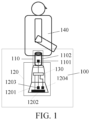
- FIG. 1 is a constructional diagram of a leg assembly for a robot according to an exemplary embodiment of this application.
- the leg assembly 100 includes: a connection assembly 110 and a plantar assembly 120.
- the connection assembly 110 is configured to connect the leg assembly 100 with an upper body 140 of the robot.
- the plantar assembly 120 includes a plantar plate 1201, a first force sensor 1202, a distance sensor 1203, and a posture sensor 1204.
- the connection assembly 110 includes a second force sensor 1101 and a shank connector 1102.
- the first force sensor 1202, the distance sensor 1203, the posture sensor 1204, and the second force sensor 1101 are electrically connected to a control unit 130.
- the leg assembly can perform comprehensive detection of a contact environment, and upload detection results of the sensors to a control unit, so that the control unit comprehensively controls the robot based on the detection results of the sensors.
- the control unit rather than obtaining a measurement result in a single aspect through detection of a single pressure sensor, more types and quality of perception information about the environment are obtained by the robot, so that the control unit can obtain a more comprehensive detection result, and control the robot to move through the leg assembly according to the detection result, thereby greatly improving a control effect on the leg assembly of the robot, thus extending application scenarios of a legged robot.
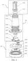
- FIG. 2 is a schematic structural diagram of a leg assembly according to an exemplary embodiment of this application.
- the leg assembly 100 includes: a connection assembly 110 and a plantar assembly 120.
- the connection assembly 110 is configured to connect the leg assembly 100 with an upper body 140 of the robot.
- the plantar assembly 120 includes a plantar plate 1201, a first force sensor 1202, a distance sensor 1203, and a posture sensor 1204.
- the connection assembly 110 includes a second force sensor 1101 and a shank connector 1102.
- the first force sensor 1202, the distance sensor 1203, the posture sensor 1204, and the second force sensor 1101 are electrically connected to a control unit 130.
- the first force sensor 1202 is configured to detect a normal reaction force applied to the plantar plate 1201 when the plantar plate 1201 is in contact with an obstacle.
- the distance sensor 1203 is configured to detect a distance between the plantar plate 1201 and the obstacle in real time.
- the posture sensor 1204 is configured to detect a spatial orientation of the plantar plate 1201.
- the second force sensor 1101 is configured to detect a resultant force of reaction forces applied to the plantar plate 1201 when the plantar plate 1201 is in contact with the obstacle.
- the plantar assembly 120 is connected with the connection assembly 110 through a joint assembly 150.
- the control unit 130 may be arranged in the leg assembly 100. Alternatively, the control unit 130 may be arranged in the upper body 140 of the robot.
- FIG. 3 is a schematic cross-sectional structural diagram of the plantar assembly 120 in the embodiment of this application.
- the plantar assembly 120 is an assembly of the robot that directly contacts the environment. Different degrees of contact between the environment and the plantar assembly 120 may be reflected by reaction forces of different magnitudes and different directions applied by the environment to the plantar assembly 120.
- the plantar assembly 120 needs to install a sensor configured to measure information generated by the robot on the contact with the environment.
- the plantar assembly 120 may include: a plantar plate 1201, a first force sensor 1202, a distance sensor 1203, a posture sensor 1204, a seal ring 1205, and plantar rubber 1206.
- a contact surface of the plantar plate 1201 with the environment is a circular plane.
- the circular plane may provide an isotropic contact condition, and facilitates mechanical modeling of a plantar contact force by using a classical Coulomb friction cone model. is a static friction force, is a coefficient of static friction, and is a normal contact force.
- a bottom and an outer side of the plantar plate 1201 are cladded with a rubber pad as the plantar rubber 1206.
- the first force sensor 1202 is arranged between the bottom of the plantar plate 1201 and the plantar rubber 1206.
- the first force sensor 1202 may be an ionic thin-film force sensor, and is arranged between the bottom of the plantar plate 1201 and the plantar rubber 1206 and is of a ring shape.
- the ionic thin-film force sensor may be configured to measure a normal contact force between the obstacle in contact with the plantar plate 1201 and the plantar plate 1201. By using the ionic thin-film force sensor, the accuracy of measuring the normal contact force can be improved, a space occupied by the force sensor of the plantar assembly 120 is reduced, and a weight of the plantar assembly 120 is also reduced.
- the distance sensor 1203 is arranged between the lower part of the plantar plate 1201 and the plantar rubber 1206 at the bottom.
- the distance sensor 1203 is arranged in a central area of the first force sensor 1202 that is of a ring shape, and the distance sensor 1203 may be a thin-film distance sensor.
- the thin-film distance sensor may be configured to measure a distance between the plantar rubber 1206 and the obstacle when the plantar plate 1201 is being close to or away from the obstacle in the environment.
- a thickness of the plantar rubber 1206 at a portion under the thin-film distance sensor is smaller than a thickness of the plantar rubber 1206 at another portion of the plantar assembly 120.
- the thin-film distance sensor may obtain a better measurement effect and have a large measurement distance. Measured values of a distance between the plantar rubber 1206 and the external environment and the normal contact force that are detected by the thin-film distance sensor and the ionic thin-film force sensor are all uploaded to a control unit 130, so that a control effect of the control unit 130 on the leg assembly 100 can be improved.
- the posture sensor 1204 is an inertial measurement unit (IMU).
- the IMU is a device configured to measure a three-axis posture angle and an acceleration of an object.
- postures of a coordinate system of the IMU relative to a coordinate system of the plantar plate 1201 may be arbitrarily arranged, and after the arranged IMU and plantar plate are calibrated, a three-axis posture angle of the plantar plate 1201 may be measured as a posture measurement value.
- a spatial orientation of the plantar plate 1201 is determined based on the posture measurement value.
- the coordinate system of the IMU and the coordinate system of the plantar plate 1201 are aligned.
- the arranged IMU and plantar plate may not be calibrated, and the posture measurement value is directly measured through the IMU.
- the IMU measures Euler angles of the plantar plate 1201 in a geographic absolute coordinate system.
- the Euler angles represent a series of three-dimensional basic rotation angles, that is, a series of rotation angles around coordinate axes of a coordinate system. For example, an angle is first formed by rotating around a z-axis, an angle is formed by rotating around an x-axis, and an angle is formed by rotating around a z-axis. According to the obtained Euler angles, the spatial orientation of the plantar plate 1201 is obtained.
- a shock absorbing gasket is arranged between the posture sensor 1204 and a metal structure part (the plantar plate 1201), to reduce interference on measurement of the posture sensor 1204 or physical damage to the posture sensor 1204 caused by a landing impact of the plantar plate 1201.
- a seal ring 1205 is configured to improve a connection effect with an upper cover of the plantar plate.
- the plantar plate 1201 is a metal structure part with a void or a groove.
- the first force sensor 1202, the distance sensor 1203, and the posture sensor 1204 are connected to the shank connector 1102 via connection wires passing through the void or the groove of the metal structure part.
- a contact surface of the plantar plate 1201 with the ground may be a circular plane.
- the connection wires may be connected to the control unit 130 in the upper body 140 of the robot through the shank connector 1102.
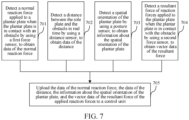
- the data of the normal reaction force, the data of the distance, the information about the spatial orientation of the plantar plate, and the vector data of the resultant force of the applied reaction forces are detected by corresponding sensors in real time.
Landscapes
- Engineering & Computer Science (AREA)
- Mechanical Engineering (AREA)
- Chemical & Material Sciences (AREA)
- Combustion & Propulsion (AREA)
- Transportation (AREA)
- Robotics (AREA)
- Human Computer Interaction (AREA)
- Manipulator (AREA)
Claims (12)
- Beinbaugruppe (100) für einen Roboter, wobei die Beinbaugruppe (100) aufweist:eine Verbindungsbaugruppe (110), die ausgebildet ist, die Beinbaugruppe (100) mit einem Oberkörper (140) des Roboters zu verbinden; undeine Plantar-Baugruppe (120), die eine plantare Platte (1201), einen ersten Kraftsensor (1202), einen Abstandssensor (1203) und einen Haltungssensor (1204) aufweist,wobei die Verbindungsbaugruppe (110) einen zweiten Kraftsensor (1101) und einen Schaftverbinder (1102) aufweist;der erste Kraftsensor (1202), der Abstandssensor (1203), der Haltungssensor (1204) und der zweite Kraftsensor (1101) elektrisch mit einer Steuereinheit (130) verbunden sind;der erste Kraftsensor (1202) ausgebildet ist, eine normale Reaktionskraft zu erfassen, die auf die plantare Platte (1201) ausgeübt wird, wenn die plantare Platte (1201) mit einem Hindernis in Kontakt ist;der Abstandssensor (1203) ausgebildet ist, einen Abstand zwischen der plantaren Platte (1201) und dem Hindernis in Echtzeit zu erfassen;der Haltungssensor (1204) ausgebildet ist, eine räumliche Ausrichtung der plantaren Platte (1201) zu erfassen; undder zweite Kraftsensor (1101) ausgebildet ist, eine resultierende Kraft von Reaktionskräften zu erfassen, die auf die plantare Platte (1201) einwirken, wenn die plantare Platte (1201) mit dem Hindernis in Kontakt ist,wobei die plantare Platte (1201) ein Metallstrukturteil mit einem Hohlraum oder einer Nut ist und der erste Kraftsensor (1202), der Abstandssensor (1203) und der Haltungssensor (1204) mit der Steuereinheit (130) über Verbindungsdrähte verbunden sind, die durch den Hohlraum oder die Nut des Metallstrukturteils verlaufen, undeine Unterseite und eine Außenseite des Metallstrukturteils mit plantarem Gummi (1206) verkleidet sind, wobeider erste Kraftsensor (1202) ein ionischer Dünnfilm-Kraftsensor ist und der ionische Dünnfilm-Kraftsensor zwischen dem plantaren Gummi (1206) und der Unterseite des Metallstrukturteils angeordnet und der ionische Dünnfilm-Kraftsensor ringförmig ist, oderder Abstandssensor (1203) ein Dünnfilm-Abstandssensor ist und der Dünnfilm-Abstandssensor mittig zwischen dem plantaren Gummi (1206) und der Unterseite des Metallstrukturteils angeordnet ist und eine Dicke des plantaren Gummis (1206) an einem Abschnitt unter dem Dünnfilm-Abstandssensor kleiner ist als eine Dicke des plantaren Gummis (1206) an einem anderen Abschnitt.
- Baugruppe gemäß Anspruch 1, wobei die Plantar-Baugruppe (120) mit der Verbindungsbaugruppe (110) durch eine Gelenkbaugruppe (150) verbunden ist unddie Gelenkbaugruppe (150) eine Gelenkkugelpfanne (1501), ein Kugelgelenk (1502) und eine elastische Baugruppe (1503) aufweist unddie plantare Platte (1201) ausgebildet ist, als Reaktion auf eine Reaktionskraft von einer Kontaktfläche die Gelenkkugelpfanne (1501) anzutreiben, um sich relativ zu dem Kugelgelenk (1502) mit drei Freiheitsgraden zu drehen, um die plantare Platte (1201) an die Kontaktfläche anzupassen.
- Baugruppe gemäß Anspruch 2, wobei die elastische Baugruppe (1503) eine konische Rückholfeder aufweist unddie konische Rückholfeder ausgebildet ist, sich in einem passiv komprimierten Zustand zu befinden, wenn die plantare Platte (1201) mit dem Hindernis in Kontakt ist; unddie konische Rückholfeder weiterhin ausgebildet ist, gespeicherte Energie freizusetzten, wenn die plantare Platte (1201) vom Hindernis getrennt wird, um die plantare Platte (1201) in einen Ausgangszustand zurückzubringen.
- Baugruppe gemäß Anspruch 2, wobei die Gelenkkugelpfanne (1501) eine Begrenzungsstruktur aufweist und
die Gelenkkugelpfanne mit der Begrenzungsstruktur mit niedrigen vorderen und hinteren Kanten und hohen linken und rechten Kanten versehen ist. - Baugruppe gemäß Anspruch 1, wobei der Haltungssensor (1204) in der Nut des Metallstrukturteils angeordnet ist.
- Baugruppe gemäß Anspruch 2, wobei die elastische Baugruppe (1503) eine konische Rückholfeder umfasst und
die konische Rückholfeder auf einem Umfang des Kugelgelenks (1502) aufgesteckt ist, und ein unteres Ende der konischen Rückholfeder mit der plantaren Platte (1201) verbunden ist, und ein oberes Ende der konischen Rückholfeder mit dem Schaftverbinder (1102) verbunden ist. - Baugruppe gemäß Anspruch 1, wobei der Schaftverbinder (1102) ein hohler dreieckiger Prismenverbinder ist, und
ein unteres Ende des Schaftverbinders (1102) mit dem zweiten Kraftsensor (1101) unter Verwendung eines Flansches verbunden ist. - Baugruppe gemäß Anspruch 1, wobei der Haltungssensor (1204) eine inertiale Messeinheit, IMU, ist.
- Baugruppe gemäß Anspruch 1, wobei der zweite Kraftsensor (1101) ein sechsachsiger Kraftsensor ist.
- Baugruppe gemäß einem der Ansprüche 1 bis 9, wobei eine Kontaktfläche der plantaren Platte (1201) mit der Umgebung eine kreisförmige Ebene ist.
- Baugruppe gemäß Anspruch 2, wobei ein Encoder an dem Kugelgelenk (1502) angeordnet ist.
- Beineinrichtung für einen Roboter, wobei die Beineinrichtung aufweist:einen Oberkörper (140) des Roboters unddie Beinbaugruppe (100) gemäß einem beliebigen der Ansprüche 1 bis 11.
Applications Claiming Priority (2)
| Application Number | Priority Date | Filing Date | Title |
|---|---|---|---|
| CN202010802986.XA CN111924020B (zh) | 2020-08-11 | 2020-08-11 | 用于机器人的腿部组件及设备 |
| PCT/CN2021/084746 WO2022033044A1 (zh) | 2020-08-11 | 2021-03-31 | 用于机器人的腿部组件及设备 |
Publications (3)
| Publication Number | Publication Date |
|---|---|
| EP4043322A1 EP4043322A1 (de) | 2022-08-17 |
| EP4043322A4 EP4043322A4 (de) | 2023-01-25 |
| EP4043322B1 true EP4043322B1 (de) | 2025-02-26 |
Family
ID=73310755
Family Applications (1)
| Application Number | Title | Priority Date | Filing Date |
|---|---|---|---|
| EP21855100.0A Active EP4043322B1 (de) | 2020-08-11 | 2021-03-31 | Beinanordnung und vorrichtung für roboter |
Country Status (5)
| Country | Link |
|---|---|
| US (1) | US12344336B2 (de) |
| EP (1) | EP4043322B1 (de) |
| JP (1) | JP7592353B2 (de) |
| CN (1) | CN111924020B (de) |
| WO (1) | WO2022033044A1 (de) |
Families Citing this family (6)
| Publication number | Priority date | Publication date | Assignee | Title |
|---|---|---|---|---|
| CN111924020B (zh) * | 2020-08-11 | 2022-07-12 | 腾讯科技(深圳)有限公司 | 用于机器人的腿部组件及设备 |
| CN113059568A (zh) * | 2021-04-07 | 2021-07-02 | 哈尔滨理工大学 | 一种多功能足端 |
| CN113401244A (zh) * | 2021-06-21 | 2021-09-17 | 北京理工大学 | 一种基于足式机器人的千斤顶自动顶升救灾系统 |
| CN115610550B (zh) * | 2021-07-13 | 2025-12-16 | Oppo广东移动通信有限公司 | 足部运动组件及足式机器人 |
| CN116161141B (zh) * | 2023-04-21 | 2023-06-30 | 成都理工大学 | 一种重载六足机器人自复位减震足端 |
| CN117381763B (zh) * | 2023-10-18 | 2024-05-31 | 芜湖藦卡机器人科技有限公司 | 一种机器人工具手自动标定检测机构及检测方法 |
Family Cites Families (22)
| Publication number | Priority date | Publication date | Assignee | Title |
|---|---|---|---|---|
| DE69840655D1 (de) * | 1997-01-31 | 2009-04-23 | Honda Motor Co Ltd | Steuerungssystem eines beweglichen Roboters mit Beinen |
| CN101763118B (zh) * | 2002-03-18 | 2015-09-02 | 索尼株式会社 | 机器人设备及其动作控制方法 |
| US7664572B2 (en) * | 2002-04-26 | 2010-02-16 | Honda Giken Kogyo Kabushiki Kaisha | Control device of legged mobile robot |
| US7145305B2 (en) * | 2002-04-26 | 2006-12-05 | Honda Giken Kogyo Kabushiki Kaisha | System for estimating attitude of leg type moving robot itself |
| JP4483254B2 (ja) | 2002-10-01 | 2010-06-16 | ソニー株式会社 | ロボット装置及びロボット装置の制御方法 |
| EP1547732A4 (de) * | 2002-10-01 | 2012-01-04 | Sony Corp | Robotervorrichtung und steuerverfahren dafür |
| KR100835361B1 (ko) * | 2003-08-29 | 2008-06-04 | 삼성전자주식회사 | 간이 지면반력 센서를 이용한 보행 로봇 및 그 제어 방법 |
| JP4466715B2 (ja) * | 2007-10-25 | 2010-05-26 | トヨタ自動車株式会社 | 脚式ロボット、及びその制御方法 |
| CN202413981U (zh) * | 2012-01-19 | 2012-09-05 | 浙江大学 | 多足步行机器人平底式脚结构 |
| JP2013208294A (ja) * | 2012-03-30 | 2013-10-10 | Equos Research Co Ltd | 歩行装置、及び歩行プログラム |
| CN103204190B (zh) * | 2013-03-11 | 2015-06-24 | 大连理工大学 | 一种机器人足部机构 |
| CN104434470B (zh) * | 2014-12-04 | 2017-01-04 | 电子科技大学 | 一种用于辅助行走的下肢外骨骼机器人 |
| CN105015641B (zh) * | 2015-07-09 | 2017-05-03 | 大连理工大学 | 一种大承载足式机器人足部机构 |
| CN105564528A (zh) * | 2016-01-14 | 2016-05-11 | 大连理工大学 | 一种机器人高适应性足部机构 |
| CN106828657B (zh) * | 2017-03-20 | 2019-02-22 | 哈尔滨工业大学 | 一种两级减振踝足一体并联低冲击行走足机构及控制方法 |
| CN108216420B (zh) * | 2018-01-23 | 2024-03-19 | 杭州云深处科技有限公司 | 一种搭载薄膜压力传感器的可调式足底机构 |
| CN108974172B (zh) * | 2018-06-07 | 2023-05-02 | 长安大学 | 一种四足机器人后肢系统踝关节与脚掌 |
| CN108714889A (zh) * | 2018-06-12 | 2018-10-30 | 广西科技师范学院 | 一种外骨骼人机系统 |
| CN108706060A (zh) * | 2018-06-26 | 2018-10-26 | 石高荣 | 智能爬楼车 |
| US12263582B2 (en) * | 2018-12-03 | 2025-04-01 | The University Of Queensland | Gyroscopically stabilised legged robot |
| CN109606500B (zh) * | 2018-12-14 | 2020-07-28 | 浙江大学 | 一种跑跳双足机器人踝足机构 |
| CN111924020B (zh) * | 2020-08-11 | 2022-07-12 | 腾讯科技(深圳)有限公司 | 用于机器人的腿部组件及设备 |
-
2020
- 2020-08-11 CN CN202010802986.XA patent/CN111924020B/zh active Active
-
2021
- 2021-03-31 JP JP2022552629A patent/JP7592353B2/ja active Active
- 2021-03-31 WO PCT/CN2021/084746 patent/WO2022033044A1/zh not_active Ceased
- 2021-03-31 EP EP21855100.0A patent/EP4043322B1/de active Active
-
2022
- 2022-05-13 US US17/743,982 patent/US12344336B2/en active Active
Also Published As
| Publication number | Publication date |
|---|---|
| US12344336B2 (en) | 2025-07-01 |
| EP4043322A1 (de) | 2022-08-17 |
| US20220266448A1 (en) | 2022-08-25 |
| EP4043322A4 (de) | 2023-01-25 |
| CN111924020B (zh) | 2022-07-12 |
| CN111924020A (zh) | 2020-11-13 |
| JP7592353B2 (ja) | 2024-12-02 |
| WO2022033044A9 (zh) | 2022-03-24 |
| WO2022033044A1 (zh) | 2022-02-17 |
| JP2023517002A (ja) | 2023-04-21 |
Similar Documents
| Publication | Publication Date | Title |
|---|---|---|
| US12344336B2 (en) | Leg assembly and device for robot | |
| EP1484134B1 (de) | Beinvorrichtung für beweglichen roboter mit beinen und verfahren zur steuerung des mit beinen versehenen beweglichen roboters | |
| JP4480843B2 (ja) | 脚式移動ロボット及びその制御方法、並びに、脚式移動ロボット用相対移動測定センサ | |
| JP4595727B2 (ja) | 外力推定システム及び外力推定方法、並びにコンピュータ・プログラム | |
| CN106547206B (zh) | 一种基于脚力估计算法的多足机器人动态稳定性定量判定方法 | |
| US7339340B2 (en) | Control system and related method for multi-limbed, multi-legged robot | |
| Catalano et al. | Adaptive feet for quadrupedal walkers | |
| KR20220080070A (ko) | 발자국 접촉 검출 | |
| JP4127043B2 (ja) | 脚式移動ロボット並びに脚式移動ロボットの関節軸として適用されるアクチュエータ装置 | |
| US7561941B2 (en) | Ambulatory robot and method for controlling the same | |
| Flacco et al. | Residual-based contacts estimation for humanoid robots | |
| Li et al. | Contact force/torque control based on viscoelastic model for stable bipedal walking on indefinite uneven terrain | |
| JP2006051564A (ja) | ロボット装置の動作制御装置及び動作制御方法 | |
| KR20010050355A (ko) | 로보트 및 로보트용 관절 장치 | |
| US8396593B2 (en) | Gait generating device of legged mobile robot | |
| Boix et al. | Modelling and control of helicopter robotic landing gear for uneven ground conditions | |
| WO2007139135A1 (ja) | ロボット及び制御装置 | |
| JP4295947B2 (ja) | 脚式移動ロボット及びその移動制御方法 | |
| CN113126659A (zh) | 一种仿人机器人跳跃着地状态检测系统与方法 | |
| US8442681B2 (en) | Desired motion evaluation apparatus of legged mobile robot | |
| JP3555945B2 (ja) | ロボット装置のためのモーション編集装置及びモーション編集方法、ロボット装置及びロボット装置の制御方法、並びにコンピュータ・プログラム | |
| CN115533898A (zh) | 一种基于非接触式电子皮肤的机械臂控制方法及系统 | |
| Shinjo et al. | Foot with a core-shell structural six-axis force sensor for pedal depressing and recovering from foot slipping during pedal pushing toward autonomous driving by humanoids | |
| Boix et al. | Helicopter lands on uneven terrain by means of articulated robotic legs-modelling, simulation and control approach | |
| de Barros et al. | An Adaptable Paw Design for Quadruped Robots Operation in Mining Environments |
Legal Events
| Date | Code | Title | Description |
|---|---|---|---|
| STAA | Information on the status of an ep patent application or granted ep patent |
Free format text: STATUS: THE INTERNATIONAL PUBLICATION HAS BEEN MADE |
|
| PUAI | Public reference made under article 153(3) epc to a published international application that has entered the european phase |
Free format text: ORIGINAL CODE: 0009012 |
|
| STAA | Information on the status of an ep patent application or granted ep patent |
Free format text: STATUS: THE APPLICATION HAS BEEN PUBLISHED |
|
| AK | Designated contracting states |
Kind code of ref document: A1 Designated state(s): AL AT BE BG CH CY CZ DE DK EE ES FI FR GB GR HR HU IE IS IT LI LT LU LV MC MK MT NL NO PL PT RO RS SE SI SK SM TR |
|
| STAA | Information on the status of an ep patent application or granted ep patent |
Free format text: STATUS: REQUEST FOR EXAMINATION WAS MADE |
|
| 17P | Request for examination filed |
Effective date: 20220817 |
|
| RBV | Designated contracting states (corrected) |
Designated state(s): AL AT BE BG CH CY CZ DE DK EE ES FI FR GB GR HR HU IE IS IT LI LT LU LV MC MK MT NL NO PL PT RO RS SE SI SK SM TR |
|
| A4 | Supplementary search report drawn up and despatched |
Effective date: 20230104 |
|
| RIC1 | Information provided on ipc code assigned before grant |
Ipc: B25J 13/08 20060101ALI20221222BHEP Ipc: B62D 57/032 20060101AFI20221222BHEP |
|
| DAV | Request for validation of the european patent (deleted) | ||
| DAX | Request for extension of the european patent (deleted) | ||
| GRAP | Despatch of communication of intention to grant a patent |
Free format text: ORIGINAL CODE: EPIDOSNIGR1 |
|
| STAA | Information on the status of an ep patent application or granted ep patent |
Free format text: STATUS: GRANT OF PATENT IS INTENDED |
|
| RIC1 | Information provided on ipc code assigned before grant |
Ipc: B25J 13/08 20060101ALI20241023BHEP Ipc: B62D 57/032 20060101AFI20241023BHEP |
|
| INTG | Intention to grant announced |
Effective date: 20241031 |
|
| GRAS | Grant fee paid |
Free format text: ORIGINAL CODE: EPIDOSNIGR3 |
|
| GRAA | (expected) grant |
Free format text: ORIGINAL CODE: 0009210 |
|
| STAA | Information on the status of an ep patent application or granted ep patent |
Free format text: STATUS: THE PATENT HAS BEEN GRANTED |
|
| AK | Designated contracting states |
Kind code of ref document: B1 Designated state(s): AL AT BE BG CH CY CZ DE DK EE ES FI FR GB GR HR HU IE IS IT LI LT LU LV MC MK MT NL NO PL PT RO RS SE SI SK SM TR |
|
| REG | Reference to a national code |
Ref country code: GB Ref legal event code: FG4D |
|
| REG | Reference to a national code |
Ref country code: CH Ref legal event code: EP |
|
| REG | Reference to a national code |
Ref country code: DE Ref legal event code: R096 Ref document number: 602021026918 Country of ref document: DE |
|
| REG | Reference to a national code |
Ref country code: IE Ref legal event code: FG4D |
|
| REG | Reference to a national code |
Ref country code: NL Ref legal event code: MP Effective date: 20250226 |
|
| PG25 | Lapsed in a contracting state [announced via postgrant information from national office to epo] |
Ref country code: RS Free format text: LAPSE BECAUSE OF FAILURE TO SUBMIT A TRANSLATION OF THE DESCRIPTION OR TO PAY THE FEE WITHIN THE PRESCRIBED TIME-LIMIT Effective date: 20250526 |
|
| PG25 | Lapsed in a contracting state [announced via postgrant information from national office to epo] |
Ref country code: FI Free format text: LAPSE BECAUSE OF FAILURE TO SUBMIT A TRANSLATION OF THE DESCRIPTION OR TO PAY THE FEE WITHIN THE PRESCRIBED TIME-LIMIT Effective date: 20250226 |
|
| PG25 | Lapsed in a contracting state [announced via postgrant information from national office to epo] |
Ref country code: PL Free format text: LAPSE BECAUSE OF FAILURE TO SUBMIT A TRANSLATION OF THE DESCRIPTION OR TO PAY THE FEE WITHIN THE PRESCRIBED TIME-LIMIT Effective date: 20250226 |
|
| PG25 | Lapsed in a contracting state [announced via postgrant information from national office to epo] |
Ref country code: ES Free format text: LAPSE BECAUSE OF FAILURE TO SUBMIT A TRANSLATION OF THE DESCRIPTION OR TO PAY THE FEE WITHIN THE PRESCRIBED TIME-LIMIT Effective date: 20250226 |
|
| REG | Reference to a national code |
Ref country code: LT Ref legal event code: MG9D |
|
| PG25 | Lapsed in a contracting state [announced via postgrant information from national office to epo] |
Ref country code: NO Free format text: LAPSE BECAUSE OF FAILURE TO SUBMIT A TRANSLATION OF THE DESCRIPTION OR TO PAY THE FEE WITHIN THE PRESCRIBED TIME-LIMIT Effective date: 20250526 Ref country code: IS Free format text: LAPSE BECAUSE OF FAILURE TO SUBMIT A TRANSLATION OF THE DESCRIPTION OR TO PAY THE FEE WITHIN THE PRESCRIBED TIME-LIMIT Effective date: 20250626 |
|
| PG25 | Lapsed in a contracting state [announced via postgrant information from national office to epo] |
Ref country code: NL Free format text: LAPSE BECAUSE OF FAILURE TO SUBMIT A TRANSLATION OF THE DESCRIPTION OR TO PAY THE FEE WITHIN THE PRESCRIBED TIME-LIMIT Effective date: 20250226 |
|
| PG25 | Lapsed in a contracting state [announced via postgrant information from national office to epo] |
Ref country code: HR Free format text: LAPSE BECAUSE OF FAILURE TO SUBMIT A TRANSLATION OF THE DESCRIPTION OR TO PAY THE FEE WITHIN THE PRESCRIBED TIME-LIMIT Effective date: 20250226 |
|
| PG25 | Lapsed in a contracting state [announced via postgrant information from national office to epo] |
Ref country code: PT Free format text: LAPSE BECAUSE OF FAILURE TO SUBMIT A TRANSLATION OF THE DESCRIPTION OR TO PAY THE FEE WITHIN THE PRESCRIBED TIME-LIMIT Effective date: 20250626 Ref country code: LV Free format text: LAPSE BECAUSE OF FAILURE TO SUBMIT A TRANSLATION OF THE DESCRIPTION OR TO PAY THE FEE WITHIN THE PRESCRIBED TIME-LIMIT Effective date: 20250226 |
|
| PG25 | Lapsed in a contracting state [announced via postgrant information from national office to epo] |
Ref country code: BG Free format text: LAPSE BECAUSE OF FAILURE TO SUBMIT A TRANSLATION OF THE DESCRIPTION OR TO PAY THE FEE WITHIN THE PRESCRIBED TIME-LIMIT Effective date: 20250226 Ref country code: GR Free format text: LAPSE BECAUSE OF FAILURE TO SUBMIT A TRANSLATION OF THE DESCRIPTION OR TO PAY THE FEE WITHIN THE PRESCRIBED TIME-LIMIT Effective date: 20250527 |
|
| REG | Reference to a national code |
Ref country code: AT Ref legal event code: MK05 Ref document number: 1770407 Country of ref document: AT Kind code of ref document: T Effective date: 20250226 |
|
| PG25 | Lapsed in a contracting state [announced via postgrant information from national office to epo] |
Ref country code: SE Free format text: LAPSE BECAUSE OF FAILURE TO SUBMIT A TRANSLATION OF THE DESCRIPTION OR TO PAY THE FEE WITHIN THE PRESCRIBED TIME-LIMIT Effective date: 20250226 |
|
| PG25 | Lapsed in a contracting state [announced via postgrant information from national office to epo] |
Ref country code: SM Free format text: LAPSE BECAUSE OF FAILURE TO SUBMIT A TRANSLATION OF THE DESCRIPTION OR TO PAY THE FEE WITHIN THE PRESCRIBED TIME-LIMIT Effective date: 20250226 |
|
| PG25 | Lapsed in a contracting state [announced via postgrant information from national office to epo] |
Ref country code: DK Free format text: LAPSE BECAUSE OF FAILURE TO SUBMIT A TRANSLATION OF THE DESCRIPTION OR TO PAY THE FEE WITHIN THE PRESCRIBED TIME-LIMIT Effective date: 20250226 |
|
| PG25 | Lapsed in a contracting state [announced via postgrant information from national office to epo] |
Ref country code: IT Free format text: LAPSE BECAUSE OF FAILURE TO SUBMIT A TRANSLATION OF THE DESCRIPTION OR TO PAY THE FEE WITHIN THE PRESCRIBED TIME-LIMIT Effective date: 20250226 |
|
| PG25 | Lapsed in a contracting state [announced via postgrant information from national office to epo] |
Ref country code: AT Free format text: LAPSE BECAUSE OF FAILURE TO SUBMIT A TRANSLATION OF THE DESCRIPTION OR TO PAY THE FEE WITHIN THE PRESCRIBED TIME-LIMIT Effective date: 20250226 |
|
| PG25 | Lapsed in a contracting state [announced via postgrant information from national office to epo] |
Ref country code: CZ Free format text: LAPSE BECAUSE OF FAILURE TO SUBMIT A TRANSLATION OF THE DESCRIPTION OR TO PAY THE FEE WITHIN THE PRESCRIBED TIME-LIMIT Effective date: 20250226 Ref country code: EE Free format text: LAPSE BECAUSE OF FAILURE TO SUBMIT A TRANSLATION OF THE DESCRIPTION OR TO PAY THE FEE WITHIN THE PRESCRIBED TIME-LIMIT Effective date: 20250226 |
|
| REG | Reference to a national code |
Ref country code: CH Ref legal event code: H13 Free format text: ST27 STATUS EVENT CODE: U-0-0-H10-H13 (AS PROVIDED BY THE NATIONAL OFFICE) Effective date: 20251023 |
|
| PG25 | Lapsed in a contracting state [announced via postgrant information from national office to epo] |
Ref country code: RO Free format text: LAPSE BECAUSE OF FAILURE TO SUBMIT A TRANSLATION OF THE DESCRIPTION OR TO PAY THE FEE WITHIN THE PRESCRIBED TIME-LIMIT Effective date: 20250226 |
|
| PG25 | Lapsed in a contracting state [announced via postgrant information from national office to epo] |
Ref country code: SK Free format text: LAPSE BECAUSE OF FAILURE TO SUBMIT A TRANSLATION OF THE DESCRIPTION OR TO PAY THE FEE WITHIN THE PRESCRIBED TIME-LIMIT Effective date: 20250226 |
|
| PG25 | Lapsed in a contracting state [announced via postgrant information from national office to epo] |
Ref country code: LU Free format text: LAPSE BECAUSE OF NON-PAYMENT OF DUE FEES Effective date: 20250331 |
|
| REG | Reference to a national code |
Ref country code: DE Ref legal event code: R097 Ref document number: 602021026918 Country of ref document: DE |
|
| REG | Reference to a national code |
Ref country code: BE Ref legal event code: MM Effective date: 20250331 |
|
| PG25 | Lapsed in a contracting state [announced via postgrant information from national office to epo] |
Ref country code: MC Free format text: LAPSE BECAUSE OF FAILURE TO SUBMIT A TRANSLATION OF THE DESCRIPTION OR TO PAY THE FEE WITHIN THE PRESCRIBED TIME-LIMIT Effective date: 20250226 |
|
| PLBE | No opposition filed within time limit |
Free format text: ORIGINAL CODE: 0009261 |
|
| STAA | Information on the status of an ep patent application or granted ep patent |
Free format text: STATUS: NO OPPOSITION FILED WITHIN TIME LIMIT |
|
| PG25 | Lapsed in a contracting state [announced via postgrant information from national office to epo] |
Ref country code: BE Free format text: LAPSE BECAUSE OF NON-PAYMENT OF DUE FEES Effective date: 20250331 |
|
| PG25 | Lapsed in a contracting state [announced via postgrant information from national office to epo] |
Ref country code: CH Free format text: LAPSE BECAUSE OF NON-PAYMENT OF DUE FEES Effective date: 20250331 |
|
| PG25 | Lapsed in a contracting state [announced via postgrant information from national office to epo] |
Ref country code: IE Free format text: LAPSE BECAUSE OF NON-PAYMENT OF DUE FEES Effective date: 20250331 |
|
| 26N | No opposition filed |
Effective date: 20251127 |
|
| PGFP | Annual fee paid to national office [announced via postgrant information from national office to epo] |
Ref country code: GB Payment date: 20260324 Year of fee payment: 6 |
|
| PGFP | Annual fee paid to national office [announced via postgrant information from national office to epo] |
Ref country code: DE Payment date: 20260320 Year of fee payment: 6 |
|
| PGFP | Annual fee paid to national office [announced via postgrant information from national office to epo] |
Ref country code: FR Payment date: 20260324 Year of fee payment: 6 |