EP4043318B1 - Steuerschaltung einer elektrischen servolenkung und verfahren zur abtastung und steuerung dafür - Google Patents
Steuerschaltung einer elektrischen servolenkung und verfahren zur abtastung und steuerung dafür Download PDFInfo
- Publication number
- EP4043318B1 EP4043318B1 EP20874341.9A EP20874341A EP4043318B1 EP 4043318 B1 EP4043318 B1 EP 4043318B1 EP 20874341 A EP20874341 A EP 20874341A EP 4043318 B1 EP4043318 B1 EP 4043318B1
- Authority
- EP
- European Patent Office
- Prior art keywords
- phase
- effect transistor
- field effect
- voltage
- bridge
- Prior art date
- Legal status (The legal status is an assumption and is not a legal conclusion. Google has not performed a legal analysis and makes no representation as to the accuracy of the status listed.)
- Active
Links
Images


Classifications
-
- B—PERFORMING OPERATIONS; TRANSPORTING
- B62—LAND VEHICLES FOR TRAVELLING OTHERWISE THAN ON RAILS
- B62D—MOTOR VEHICLES; TRAILERS
- B62D5/00—Power-assisted or power-driven steering
- B62D5/04—Power-assisted or power-driven steering electrical, e.g. using an electric servo-motor connected to, or forming part of, the steering gear
- B62D5/0457—Power-assisted or power-driven steering electrical, e.g. using an electric servo-motor connected to, or forming part of, the steering gear characterised by control features of the drive means as such
- B62D5/046—Controlling the motor
- B62D5/0463—Controlling the motor calculating assisting torque from the motor based on driver input
-
- B—PERFORMING OPERATIONS; TRANSPORTING
- B62—LAND VEHICLES FOR TRAVELLING OTHERWISE THAN ON RAILS
- B62D—MOTOR VEHICLES; TRAILERS
- B62D5/00—Power-assisted or power-driven steering
- B62D5/04—Power-assisted or power-driven steering electrical, e.g. using an electric servo-motor connected to, or forming part of, the steering gear
- B62D5/0457—Power-assisted or power-driven steering electrical, e.g. using an electric servo-motor connected to, or forming part of, the steering gear characterised by control features of the drive means as such
- B62D5/0481—Power-assisted or power-driven steering electrical, e.g. using an electric servo-motor connected to, or forming part of, the steering gear characterised by control features of the drive means as such monitoring the steering system, e.g. failures
- B62D5/0487—Power-assisted or power-driven steering electrical, e.g. using an electric servo-motor connected to, or forming part of, the steering gear characterised by control features of the drive means as such monitoring the steering system, e.g. failures detecting motor faults
-
- B—PERFORMING OPERATIONS; TRANSPORTING
- B62—LAND VEHICLES FOR TRAVELLING OTHERWISE THAN ON RAILS
- B62D—MOTOR VEHICLES; TRAILERS
- B62D5/00—Power-assisted or power-driven steering
- B62D5/04—Power-assisted or power-driven steering electrical, e.g. using an electric servo-motor connected to, or forming part of, the steering gear
- B62D5/0457—Power-assisted or power-driven steering electrical, e.g. using an electric servo-motor connected to, or forming part of, the steering gear characterised by control features of the drive means as such
- B62D5/046—Controlling the motor
-
- H—ELECTRICITY
- H02—GENERATION; CONVERSION OR DISTRIBUTION OF ELECTRIC POWER
- H02H—EMERGENCY PROTECTIVE CIRCUIT ARRANGEMENTS
- H02H7/00—Emergency protective circuit arrangements specially adapted for specific types of electric machines or apparatus or for sectionalised protection of cable or line systems, and effecting automatic switching in the event of an undesired change from normal working conditions
- H02H7/10—Emergency protective circuit arrangements specially adapted for specific types of electric machines or apparatus or for sectionalised protection of cable or line systems, and effecting automatic switching in the event of an undesired change from normal working conditions for converters; for rectifiers
- H02H7/12—Emergency protective circuit arrangements specially adapted for specific types of electric machines or apparatus or for sectionalised protection of cable or line systems, and effecting automatic switching in the event of an undesired change from normal working conditions for converters; for rectifiers for static converters or rectifiers
- H02H7/122—Emergency protective circuit arrangements specially adapted for specific types of electric machines or apparatus or for sectionalised protection of cable or line systems, and effecting automatic switching in the event of an undesired change from normal working conditions for converters; for rectifiers for static converters or rectifiers for inverters, i.e. DC/AC converters
-
- H—ELECTRICITY
- H02—GENERATION; CONVERSION OR DISTRIBUTION OF ELECTRIC POWER
- H02P—CONTROL OR REGULATION OF ELECTRIC MOTORS, ELECTRIC GENERATORS OR DYNAMO-ELECTRIC CONVERTERS; CONTROLLING TRANSFORMERS, REACTORS OR CHOKE COILS
- H02P29/00—Arrangements for regulating or controlling electric motors, appropriate for both AC and DC motors
- H02P29/02—Providing protection against overload without automatic interruption of supply
- H02P29/024—Detecting a fault condition, e.g. short circuit, locked rotor, open circuit or loss of load
- H02P29/0243—Detecting a fault condition, e.g. short circuit, locked rotor, open circuit or loss of load the fault being a broken phase
-
- H—ELECTRICITY
- H02—GENERATION; CONVERSION OR DISTRIBUTION OF ELECTRIC POWER
- H02P—CONTROL OR REGULATION OF ELECTRIC MOTORS, ELECTRIC GENERATORS OR DYNAMO-ELECTRIC CONVERTERS; CONTROLLING TRANSFORMERS, REACTORS OR CHOKE COILS
- H02P6/00—Arrangements for controlling synchronous motors or other dynamo-electric motors using electronic commutation dependent on the rotor position; Electronic commutators therefor
- H02P6/08—Arrangements for controlling the speed or torque of a single motor
Definitions
- the present invention relates to the control technical field of an electric power steering system, in particular to a controller circuit of an electric power steering system, and a sampling and control method thereof.
- the electric power steering system has the advantages of small size, light weight, simple structure, high efficiency, energy saving and environmental protection, and flexible control methods and so on, which has become an indispensable part of automobiles.
- the controller circuit design and its control method of the electric power steering system are the core of the electric power steering system, the suppliers of the electric power steering system or controller at home and abroad have their own controller circuit design and control method, and the core functions mainly realized are the control of the booster motor and the functional safety design of the steering system.
- the electric power steering system controller has relatively high requirements for safety performance, before the controller works normally, the three-phase bridge power-on fault must be diagnosed, specifically the switch of each field-effect transistor in the three-phase bridge module, after ensuring that each switch is normal, the controller can start the three-phase bridge driving chip to carry out PWM (Pulse width modulation) control on the three-phase bridge, so that the motor can generate a boosted power.
- PWM Pulse width modulation
- the existing electric power steering system controller circuit is not accurate enough for the diagnosis of the field-effect transistor of the three-phase bridge module.
- the motor boosted power needs to be cut off, it is easy to impact or even damage the phase separation switch field effect transistor on the controller.
- the sampling precision is relatively poor when the current value flowing through the motor changes in a larger range.
- the control circuit of the existing booster motor cannot quickly and simply control the switch and the boosted power input of the motor in real time, and the protection and diagnosis mechanism for the controller is not comprehensive enough, therefore, it is very necessary to design a controller circuit of an electric power steering system, and a sampling and control method thereof, in which a variety of measures are used to improve the functional safety level of the electric power steering system; the control performance of the booster motor is more stable; and the protection and diagnosis mechanism for the controller is more comprehensive, which makes the controller safer and more reliable, and not easily damaged.
- CN 105 629 122 A discloses a circuit and diagnostic method for static diagnosis of a three-phase full-bridge inverter.
- EP 2 731 257 A1 discloses a motor control device.
- the technical problem to be solved by the present invention is to overcome the defect that the diagnosis of the field-effect transistor of the three-phase bridge module in the electric power steering system controller circuit in the prior art is not accurate enough, and to provide a controller circuit of an electric power steering system, and a sampling and control method thereof which can easily and conveniently perform the three-phase bridge power-on fault diagnosis.
- controller circuit according to claim 1, a sampling method according to claim 4, a controller circuit of an electric power steering system according to claim 6, and a control method according to claim 10. Preferred features are set out in the dependent claims.
- the first aspect of the present invention provides a controller circuit of an electric power steering system, including a three-phase electric motor, a micro-controller, a three-phase bridge module, and a three-phase electric motor phase voltage state feedback circuit;
- the three-phase electric motor phase voltage state feedback circuit realizes power-on fault diagnosis for the field-effect transistors in the three-phase bridge module through three pull-up circuits, which improves the diagnosis coverage rate of the field-effect transistor.
- the voltage at the voltage dividing output end corresponding to the U-phase end is a U-phase feedback voltage
- the present solution further defines the specific way that the micro-controller performs power-on fault diagnosis on the field-effect transistor in the three-phase bridge module, which realizes the accurate diagnosis for each field-effect transistor in the three-phase bridge module.
- the pull-up circuit corresponding to the U-phase end includes a first resistor
- the voltage dividing circuit corresponding to the U-phase end includes a second resistor and a third resistor
- one end of the first resistor is electrically connected with the vehicle power supply
- both of the other end of the first resistor and one end of the second resistor are electrically connected with the original voltage end of the voltage dividing circuit corresponding to the U-phase end
- both of the other end of the second resistor and one end of the third resistor are electrically connected with the voltage dividing output end of the voltage dividing circuit corresponding to the U-phase end, and the other end of the third resistor is grounded;
- the controller circuit further includes a three-phase separation module, the three-phase separation module is connected in series between the three-phase electric motor and the three-phase bridge module, and the three-phase separation module is used to cut off the connection between the three-phase electric motor and the three-phase bridge module when the steering system controller fails.
- the three-phase separation module includes a U-phase separation field-effect transistor, a V-phase separation field-effect transistor, and a W-phase separation field-effect transistor;
- the controller circuit also includes a motor freewheeling circuit;
- the motor freewheeling circuit includes a U-phase diode, a V-phase diode, and a W-phase diode; and the anode of the U-phase diode, the anode of the V-phase diode, and the anode of the W-phase diode are all grounded;
- the diodes of the three phases in the motor freewheeling circuit are set at the drive end of the corresponding phase separation field-effect transistor transistor to provide the drive current for each phase separation field-effect transistor to turn on, and turn on the phase separation field-effect transistor when the negative voltage of the three-phase electric motor is generated, to form a freewheeling channel, which provides a way to release the energy of the three-phase electric motor and avoid damaging the related components in the circuit.
- the second aspect of the present invention provides a sampling method for the three-phase phase current of the controller circuit of an electric power steering system
- the present solution achieves a phase current sampling method that can keep the three-phase current sampling at a higher precision under various currents with different magnitudes, and solves the problem that in the existing motor control, the fixed gains and the bias voltage are used in all the three-phase current sampling, high-precision sampling can only be achieved within a certain current interval when the current value flowing through the motor changes within a relatively large range, and the accuracy is poor when sampling outside this interval.
- the gain value and the bias voltage value of the differential operational amplifier in the current cycle is set according to the actual value of the phase current of the previous cycle of the current cycle and/or the duty ratio of the PWM control signal of the previous cycle of the current cycle, to make the gain value and bias voltage value match the current range of the current measured, thereby control the phase current of the three-phase electric motor to maintain a high sampling accuracy, and then the motor control performance of power steering system is improved.
- the sampling method is implemented based on the controller circuit of the electric power steering system aforementioned in the first aspect.
- the three-phase phase current sampling circuit module includes a current sampling resistor for collecting the phase voltage signals of the lower-bridge arms of the two phases in the three-phase bridge module, and the collected phase voltage signals are a first phase voltage signal and a second phase voltage signal respectively, the actual value of the phase current corresponding to the first phase voltage signal is the actual value of the first phase current, and the actual value of the phase current corresponding to the second phase voltage signal is the actual value of the second phase current; the sampling method further includes the following steps:
- the present solution based on the characteristic that the motor current does not dramatically change but slowly changes, perform judgment according to the phase current vector length Is of the previous cycle of the current cycle and/or the internal where the duty ratio of the PWM control signal of the previous cycle of the current cycle is located, that is, make the gain value and the bias voltage value match the range of the present measured current by setting the gain value and the bias voltage value of the corresponding differential operational amplifier according to the interval, thereby control the phase current of the three-phase electric motor to keep a relatively high sampling precision, and then improve the motor control performance of the power steering system.
- the step of setting the gain value and the bias voltage value of the differential operational amplifier of the current cycle according to the partition where the measured current is located includes: the micro-controller sets the gain value and the bias voltage value of the differential operational amplifier in the current cycle through SPI (Serial Peripheral Interface) instructions according to the partition where the measured current is located.
- SPI Serial Peripheral Interface
- the gain value and bias voltage value of the differential operational amplifier are modified through SPI instructions in each control cycle of the analog-to-digital converter for different regions, so as to control the sampling precision of the phase current of the three-phase electric motor.
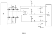
- the third aspect of the present invention provides a controller circuit of an electric power steering system, including a micro-controller, a power management chip, a power interface filter circuit module, a DC voltage stabilizer module, a three-phase bridge driving chip, a three-phase separation circuit driving chip, a CAN (Controller Area Network) transceiver, and a permanent magnet synchronous motor, one end of the battery is grounded, and the other end of the battery is connected in series with a fuse then divided into two channels, which are respectively connected with the power input port of the power management chip and the power input port of the power interface filter circuit module, and the power output port of the power interface filter circuit module is divided into two channels, which are respectively connected with the power input port of the three-phase bridge driving chip and the current input port of the DC voltage stabilizer module, and the current output of the DC voltage stabilizer module is connected to the current input port of the three-phase bridge module, the V MCU port of the power management chip is connected with the power input port of the micro-controller, and the SPI port of the power
- a three-phase electric motor phase voltage state feedback circuit is also arranged and connected with between the three-phase bridge module, the three-phase bridge driving chip and the micro-controller.
- the three-phase separation module is also connected with a low-power diode, so that a motor freewheeling circuit is formed among the three-phase bridge module, the three-phase separation module, and the low-power diode.
- the VBAT port is divided into nine channels, which are respectively connected with one end of the capacitor C1, one end of the capacitor C2, one end of the capacitor C3, one end of the capacitor C4, and one end of the capacitor C5, one end of the capacitor C6, one end of the capacitor C7, one end of the capacitor C8, and one end of the inductor L1
- the other end of the capacitor C1 is divided into four channels, which are respectively connected with HGND, one end of the capacitor C14, the other end of the capacitor C2, and one end of the capacitor C15, the other end of the capacitor C14 is joined with the other end of the capacitor C15 together then grounded
- the other end of the capacitor C3 is divided into eleven channels, which are respectively connected with the ground, the other end of the capacitor C4, the other end of the capacitor C5, the other end of the capacitor C6, the other end of the capacitor C7, the other end of the capacitor C8, one end of the capacitor C9, one end of the capacitor C10, one end
- the HGND, HGND1, HGND2, and HGND3 are the screw holes on the metal shell.
- the VBAT port is divided into three channels, which are respectively connected with the drain electrode of the field-effect transistor Q1, the drain electrode of the field-effect transistor Q2, and the drain electrode of the field-effect transistor Q3, and the source electrode of the field-effect transistor Q1 is divided into two channels, which are respectively connected with the drain electrode of the field-effect transistor Q4 and the drain electrode of the field-effect transistor Q7, the source electrode of field-effect transistor Q7 is connected with the U-phase of the three-phase electric motor, and the gate electrode of the field-effect transistor Q7 is connected with the cathode of the diode D1, the source electrode of the field-effect transistor Q2 is divided into two channels, which are respectively connected with the drain electrode of the field-effect transistor Q8 and the drain electrode of the field-effect transistor Q5, and the gate electrode of the field-effect transistor Q8 is connected with the diode D2, the source electrode of the field-effect transistor Q8 is connected with the V-phase of the three-phase electric motor
- the U-phase of the three-phase electric motor is divided into four channels, which are respectively connected with the source electrode of the field-effect transistor Q1, the drain electrode of the field-effect transistor Q4, one end of the resistor R1, and one end of the resistor R2
- the V-phase of the three-phase electric motor is divided into four channels, which are respectively connected with the source electrode of the field-effect transistor Q2
- the W-phase of the three-phase electric motor is divided into four channels, which are respectively connected with the source electrode of the field-effect transistor Q3, the drain electrode of the field-effect transistor Q6, one end of the resistor R7, one end of the resistor R8, the drain electrode of the field-effect transistor Q1, the drain electrode of the field-effect transistor Q2, the drain electrode of the field-effect transistor Q3 are joined together then connected with VBAT, the source electrode of the field-effect transistor
- the gate electrodes of the field-effect transistors Q1 to Q6 are jointed together then connected with the three-phase bridge driving chip.
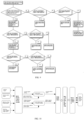
- the fourth aspect of the present invention provides a control method of the controller circuit in the electric power steering system, which is performed as follows:
- step 2 The specific calculation method of step 2 is as follows:
- the positive progressive effect of the present invention is that: compared with the prior art, the three-phase electric motor phase voltage state feedback circuit in the present invention timely feeds back the true phase voltage of the three-phase electric motor for assisting the motor control, and at the same time, achieves the accurate diagnosis for each field-effect transistor in the three-phase bridge module by the three pull-up circuits, and improves the diagnosis coverage of the field-effect transistor.
- the diodes of three phases in the motor freewheeling circuit are set at the drive end of the corresponding phase separation field-effect transistor, and when the controller of the electric power steering system needs to cut off the motor boosted power, provides a driving current for each phase separation field-effect transistor to turn on, and turns on the phase separation field-effect transistor when the negative voltage is generated in the three-phase electric motor, to form a freewheeling channel, which provides a way to release the energy of the three-phase electric motor and avoid damaging related components in the circuit.
- the present solution further achieves a phase current sampling method that can keep the three-phase current sampling at a relatively high precision under various currents with different magnitudes, and solves the problem that in the existing motor control, uses a fixed gain and bias voltage in all the three phases current sampling, high-precision sampling can only be achieved within a certain current interval when the current value flowing through the motor changes in a relatively large range, and the precision is poor when sampling outside this interval.
- the positive progressive effect of the present invention is: compared with the prior art, the present invention applies the latest generation motor rotation angle position sensor, which greatly improves the control performance of the motor; applies a three-phase separation circuit to make SCU (Steering Control Unit) can ensure to cut off the motor boosted power under a fault state, and the safety of the steering system is greatly improved, and the present invention can reduce the failure rate of the SCU to below 500 FIT (FIT, a failure rate unit).
- FIT a failure rate unit
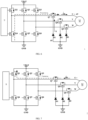
- this embodiment provides a controller circuit of an electric power steering system, which includes a three-phase electric motor 18, a micro-controller 1, a three-phase bridge module 5, a three-phase bridge driving chip 9 and a three-phase electric motor phase voltage state feedback circuit 14.
- the three-phase electric motor 18 includes a U-phase end 1801, a V-phase end 1802 and a W-phase end 1803.
- the micro-controller 1 includes at least three analog-to-digital conversion voltage collection ends, which are U-phase analog-to-digital conversion voltage collection end AD1, V-phase analog-to-digital conversion voltage collection end AD2, and W-phase analog-to-digital conversion voltage collection end AD3 respectively.
- the three-phase bridge module 5 includes U-phase upper-bridge field-effect transistor Q1, U-phase lower-bridge field-effect transistor Q4, V-phase upper-bridge field-effect transistor Q2, V-phase lower-bridge field-effect transistor Q5, W-phase upper-bridge field-effect transistor Q3 and W-phase lower-bridge field-effect transistor Q6.
- the three-phase electric motor phase voltage state feedback circuit 14 includes three voltage dividing circuits, namely, U-phase voltage dividing circuit 1404, V-phase voltage dividing circuit 1405, and W-phase voltage dividing circuit 1406.
- Each voltage dividing circuit includes an original voltage end, a voltage dividing output end, and a grounding end, the three original voltage ends are one by one correspondingly connected with the U-phase end 1801, the V-phase end 1802, and the W-phase end 1803.
- the U-phase voltage dividing circuit 1404 includes a U-phase original voltage end 14041, a U-phase voltage dividing output end 14042, and a U-phase grounding end 14043;
- the V-phase voltage dividing circuit 1405 includes a V-phase original voltage end 14051 and a V-phase voltage dividing output end 14052 and the V-phase grounding end 14053;
- the W-phase voltage dividing circuit 1406 includes a W-phase original voltage end 14061, a W-phase voltage dividing output end 14062 and a W-phase grounding end 14063.
- the three voltage dividing output ends are electrically connected with the three analog-to-digital conversion voltage collection ends in a one-to-one correspondence; that is, the U-phase voltage dividing output end 14042 is electrically connected with the U-phase analog-to-digital conversion voltage collection end AD1, and the V-phase voltage dividing output end 14052 is electrically connected with the V-phase analog-to-digital conversion voltage collection end AD2, and the W-phase voltage dividing output end 14062 is electrically connected with the W-phase analog-to-digital conversion voltage collection end AD3.
- the voltage dividing circuit is used to divide the phase voltage of the three-phase electric motor 18 to be within the voltage range supported by the analog-to-digital conversion voltage collection end.
- the U-phase end 1801 is electrically connected with the source electrode of the U-phase upper-bridge field-effect transistor Q1, the drain electrode of the U-phase lower-bridge field-effect transistor Q4, and the original voltage end of the corresponding voltage dividing circuit, that is, the U-phase original voltage end 14041.
- the V-phase end 1802 is electrically connected with the source electrode of the V-phase upper-bridge field-effect transistor Q2, the drain electrode of the V-phase lower-bridge field-effect transistor Q5, and the original voltage end of the corresponding voltage dividing circuit, that is, the V-phase original voltage end 14051.
- the W-phase end 1803 is electrically connected with the source electrode of the W-phase upper-bridge field-effect transistor Q3, the drain electrode of the W-phase lower-bridge field-effect transistor Q6, and the original voltage end of the corresponding voltage dividing circuit, that is, the W-phase original voltage end 14061.
- the three-phase electric motor phase voltage state feedback circuit 14 further includes three pull-up circuits, that is, a U-phase pull-up circuit 1401, a V-phase pull-up circuit 1402, and a W-phase pull-up circuit 1403.
- the three pull-up circuits are used to pull up the U-phase end 1801, the V-phase end 1802, and the W-phase end 1803 in a one-to-one correspondence; that is, the U-phase pull-up circuit 1401 is used to pull up the U-phase end 1801, and the V-phase pull-up circuit 1402 is used to pull up the V-phase end 1802, and the W-phase pull-up circuit 1403 is used to pull up the W-phase end 1803.
- the micro-controller 1 is used to perform power-on fault diagnosis for the U-phase upper-bridge field-effect transistor Q1 and/or the U-phase lower-bridge field-effect transistor Q4, by controlling the on or off of the U-phase upper-bridge field-effect transistor Q1 and the U-phase lower-bridge field-effect transistor Q4 respectively, and based on the voltage collected by the corresponding analog-to-digital conversion voltage collection end; the micro-controller 1 is also used to perform power-on fault diagnosis for the V-phase upper-bridge field-effect transistor Q2 and/or the V-phase lower-bridge field-effect transistor Q5, by controlling the on or off of the V-phase upper-bridge field-effect transistor Q2 and the V-phase lower-bridge field-effect transistor Q5 respectively, and based on the voltage collected by the corresponding analog-to-digital conversion voltage collection end; the micro-controller 1 is also used to perform power-on fault diagnosis for the W-phase upper-bridge field-effect transistor Q3 and/or the W-phase lower-bridge field-effect transistor Q6, by
- the pull-up circuit corresponding to the U-phase end 1801, that is, the U-phase pull-up circuit 1401, includes a first resistor R1
- the voltage dividing circuit corresponding to the U-phase end 1801, that is, the U-phase voltage dividing circuit 1404 includes a first capacitor C21, a second resistor R2 and a third resistor R3, one end of the first resistor R1 is electrically connected with the vehicle power supply VBAT
- the other end of the first resistor R1 and one end of the second resistor R2 are both electrically connected with the U-phase original voltage end 14041
- the other end of the second resistor R2 and one end of the third resistor R3 are both electrically connected with the U-phase voltage dividing output end 14042
- the other end of the third resistor R3 is ground connected with GND via the U-phase ground end 14043.
- the vehicle power supply VBAT is the power supply provided by the battery on the vehicle where the controller circuit of the electric power steering system of this embodiment is located.
- the pull-up circuit corresponding to the W-phase end 1803, that is, the W-phase pull-up circuit 1403, includes a seventh resistor R7
- the voltage dividing circuit corresponding to the W-phase end 1803, that is, the W-phase voltage dividing circuit 1406 includes a third capacitor C23, a eighth resistor R8 and a ninth resistor R9
- one end of the seventh resistor R7 is electrically connected with the vehicle power supply VBAT
- the other end of the seventh resistor R7 and one end of the eighth resistor R8 are both electrically connected with the W-phase original voltage end 14061
- the other end of the eighth resistor R8 and one end of the ninth resistor R9 are both electrically connected with the W-phase voltage dividing output end 14062
- the other end of the ninth resistor R9 is ground connected with GND via the W-phase ground end 14063.
- the voltage of the U-phase voltage dividing output end 14042 corresponding to the U-phase end 1801 is the U-phase feedback voltage; the U-phase first default value is VBAT*(R3)/(R2+R3), and the U-phase second default value is VBAT*(R3)/(R1+R2+R3).
- the micro-controller 1 is also used to control the U-phase upper-bridge field-effect transistor Q1 to turn off, and at the same time, control the U-phase lower-bridge field-effect transistor Q4 to turn on, then obtain the U-phase feedback voltage and use it as a third U-phase feedback voltage, and when the third U-phase feedback voltage is equal to 0, determine that both the U-phase upper-bridge field-effect transistor Q1 and the U-phase lower-bridge field-effect transistor Q4 work normally, when the third U-phase feedback voltage is not equal to 0, determine that the U-phase lower-bridge field-effect transistor Q4 has a broken circuit fault.
- the voltage of the V-phase voltage dividing output end 14052 corresponding to the V-phase end 1802 is the V-phase feedback voltage; the V-phase first default value is VBAT*(R6)/(R5+R6), and the V-phase second default value is VBAT*(R6)/(R4+R5+R6).
- the micro-controller 1 is used to control both the V-phase upper-bridge field-effect transistor Q2 and the V-phase lower-bridge field-effect transistor Q5 to turn off, then obtain the V-phase feedback voltage and use it as a first V-phase feedback voltage, when the first V-phase feedback voltage is equal to a V-phase first default value, determine that the V-phase upper-bridge field-effect transistor Q2 has a short circuit fault, and when the first V-phase feedback voltage is equal to 0, determine that the V-phase lower-bridge field-effect transistor Q5 has a short circuit fault, when the first V-phase feedback voltage is not equal to the V-phase first default value and not equal to 0 and not equal to a V-phase second default value, determine that the V-phase upper-bridge field-effect transistor Q2 and the V-phase lower-bridge field-effect transistor Q5 are in an unexpected status.
- the micro-controller 1 When the first V-phase feedback voltage is equal to the V-phase second default value, the micro-controller 1 is also used to control the V-phase upper-bridge field-effect transistor Q2 to turn on, and at the same time, control the V-phase lower-bridge field-effect transistor Q5 to turn off, then obtain the V-phase feedback voltage and use it as a second V-phase feedback voltage, and when the second V-phase feedback voltage is not equal to the V-phase first default value, determine that the V-phase upper-bridge field-effect transistor Q2 has a broken circuit fault.
- the micro-controller 1 is also used to control the V-phase upper-bridge field-effect transistor Q2 to turn off, and at the same time, control the V-phase lower-bridge field-effect transistor Q5 to turn on, then obtain the V-phase feedback voltage and use it as a third V-phase feedback voltage, and when the third V-phase feedback voltage is equal to 0, determine that both the V-phase upper-bridge field-effect transistor Q2 and the V-phase lower-bridge field-effect transistor Q5 work normally, when the third V-phase feedback voltage is not equal to 0, determine that the V-phase lower-bridge field-effect transistor Q5 has a broken circuit fault.
- the voltage of the W-phase voltage dividing output end 14062 corresponding to the W-phase end 1803 is the W-phase feedback voltage;
- the W-phase first default value is VBAT*(R9)/(R8+R9), and the W-phase second default value is VBAT*(R9)/(R7+R8+R9).
- the micro-controller 1 is used to control both the W-phase upper-bridge field-effect transistor Q3 and the W-phase lower-bridge field-effect transistor Q6 to turn off, then obtain the W-phase feedback voltage and use it as a first W-phase feedback voltage, when the first W-phase feedback voltage is equal to a W-phase first default value, determine that the W-phase upper-bridge field-effect transistor Q3 has a short circuit fault, and when the first W-phase feedback voltage is equal to 0, determine that the W-phase lower-bridge field-effect transistor Q6 has a short circuit fault, when the first W-phase feedback voltage is not equal to the W-phase first default value and not equal to 0 and not equal to a W-phase second default value, determine that the W-phase upper-bridge field-effect transistor Q3 and the W-phase lower-bridge field-effect transistor Q6 are in an unexpected status.
- the micro-controller 1 when the first W-phase feedback voltage is equal to the W-phase second default value, the micro-controller 1 is also used to control the W-phase upper-bridge field-effect transistor Q3 to turn on, and at the same time, control the W-phase lower-bridge field-effect transistor Q6 to turn off, then obtain the W-phase feedback voltage and use it as a second W-phase feedback voltage, and when the second W-phase feedback voltage is not equal to the W-phase first default value, determine that the W-phase upper-bridge field-effect transistor Q3 has a broken circuit fault.
- the micro-controller 1 is also used to control the W-phase upper-bridge field-effect transistor Q3 to turn off, and at the same time, control the W-phase lower-bridge field-effect transistor Q6 to turn on, then obtain the W-phase feedback voltage and use it as a third W-phase feedback voltage, and when the third W-phase feedback voltage is equal to 0, determine that both the W-phase upper-bridge field-effect transistor Q3 and the W-phase lower-bridge field-effect transistor Q6 work normally, when the third W-phase feedback voltage is equal to the W-phase second default value, determine that the W-phase lower-bridge field-effect transistor Q6 has a broken circuit fault, when the third W-phase feedback voltage is not equal to 0, determine that the W-phase lower-bridge field-effect transistor Q6 has a broken circuit fault.
- the three-phase electric motor phase voltage state feedback circuit realizes the power-on fault diagnosis for the field-effect transistor in the three-phase bridge module by three pull-up circuits, which improves the diagnosis coverage rate of the field-effect transistor.
- the controller circuit of the electric power steering system provided in this embodiment further includes a three-phase separation module 6 and a motor freewheeling circuit 15.
- the three-phase separation module 6 is connected in series between the three-phase electric motor 18 and the three-phase bridge module 5, and the three-phase separation module 6 is used to cut off the connection between the three-phase electric motor 18 and the three-phase bridge module 5 when the steering system controller fails.
- the three-phase separation module 6 includes a U-phase separation field-effect transistor Q7, a V-phase separation field-effect transistor Q8, and a W-phase separation field-effect transistor Q9.
- the motor freewheeling circuit 15 includes a U-phase diode D1, a V-phase diode D2, and a W-phase diode D3; the anode of the U-phase diode D1, the anode of the V-phase diode D2 and the anode of the W-phase diode D3 are all grounded.
- the grid electrode of the U-phase separation field-effect transistor Q7 is electrically connected with the cathode of the U-phase diode D1
- the source electrode of the U-phase separation field-effect transistor Q7 is electrically connected with the U-phase end 1801
- the drain electrode of the U-phase separation field-effect transistor Q7 is electrically connected with the source electrode of the U-phase upper-bridge field-effect transistor Q1.
- the grid electrode of the V-phase separation field-effect transistor Q8 is electrically connected with the cathode of the V-phase diode D2
- the source electrode of the V-phase separation field-effect transistor Q8 is electrically connected with the V-phase end 1802
- the drain electrode of the V-phase separation field-effect transistor Q8 is electrically connected with the source electrode of the V-phase upper-bridge field-effect transistor Q2.
- the grid electrode of the W-phase separation field-effect transistor Q9 is electrically connected with the cathode of the W-phase diode D3, the source electrode of the W-phase separation field-effect transistor Q9 is electrically connected with the W-phase end 1803, and the drain electrode of the W-phase separation field-effect transistor Q9 is electrically connected with the source electrode of the W-phase upper-bridge field-effect transistor Q3.
- the power of the U-phase diode D1, the V-phase diode D2, and the W-phase diode D3 is about 0.3W (watt)
- these three diodes are all placed on the drive end of the corresponding phase separation field-effect transistor to provide the driving current turned on by the phase separation field-effect transistor, it needs to turn on the phase separation field-effect transistor once the negative voltage of the motor is generated, to form a freewheeling channel, the driving power of the phase separation field-effect transistor is relatively low, so these three diodes can select a diode with relatively low power.
- the three phase diodes with extremely low power in the motor freewheeling circuit are set at the drive end of the corresponding phase separation field-effect transistor to provide the drive current for each phase separation field-effect transistor to turn on, and turn on the phase separation field-effect transistor once the negative voltage of the three-phase electric motor is generated, to form a freewheeling circuit, which provides a way to release the energy of the three-phase electric motor and avoid damaging the relevant components in the circuit.
- the controller circuit includes a three-phase electric motor, a micro-controller, a three-phase bridge module, a three-phase phase current sampling circuit module, and a three-phase bridge driving chip.
- the micro-controller is used to generate a PWM control signal and transmit it to the three-phase bridge driving chip.
- the three-phase bridge driving chip is used to control the on or off of each field-effect transistor in the three-phase bridge module according to the PWM control signal.
- the sampling method can be implemented based on the embodiment 1 or the embodiment 2 or the controller circuit of an existing electric power steering system.
- the sampling method includes the following steps:
- the three-phase phase current sampling circuit module includes the current sampling resistors for collecting the phase voltage signals of the lower-bridge arms of the two phases in the three-phase bridge module, and the collected phase voltage signals are a first phase voltage signal and a second phase voltage signal respectively, the actual value of the phase current corresponding to the first phase voltage signal is the actual value of the first phase current, and the actual value of the phase current corresponding to the second phase voltage signal is the actual value of the second phase current.
- I P1 represents the actual value of the first phase current
- I P2 represents the actual value of the second phase current.
- the current implementation of the three-phase phase current sampling circuit module requires the current sampling resistors for the phase voltage signal of the lower-bridge arm from the three phases, compared with the existing implementation, this embodiment reduces one phase, that is, the current sampling resistors corresponding to only two of the three phases are required, the value of the current vector length Is can be calculated.
- the two phases can be any two of U-phase, V-phase and W-phase. This embodiment can reduce circuit complexity and hardware cost.
- the step of setting the gain value and the bias voltage value of the differential operational amplifier of the current cycle according to the actual value of the phase current of the previous cycle of the current cycle and/or the duty ratio of the PWM control signal of the previous cycle of the current cycle includes the following steps:
- the current sampling precision can be controlled by changing the gain value and the bias voltage value of the amplifier according to the different measured current sampling ranges under the condition that the sampling resistance value is constant, realizes a phase current sampling method that can keep the three-phase current sampling at a relatively high precision under various currents with different magnitudes, solves the problem of using a fixed gain and bias voltage in all three phases current sampling in the existing motor control, when the current value flowing through the motor changes in a relatively large range, high-precision sampling can only be achieved in a certain current interval, when sampling outside this interval, then the precision is relatively poor.
- the detailed description of the above principle is described in the subsequent embodiment 4, and will not be repeated here.
- This embodiment is based on the characteristic that the motor current does not dramatically change but slowly changes, the gain value and the bias voltage value of the differential operational amplifier in the current cycle is set according to the actual value of the phase current of the previous cycle of the current cycle and/or the duty ratio of the PWM control signal of the previous cycle of the current cycle, to make the gain value and the bias voltage value match the range of the present measured current, thereby control the phase current of the three-phase electric motor to keep a high sampling precision, and then improves the motor control performance of the steering system.
- the present invention designs a controller circuit of an electric power steering system, including a micro-controller 1, a power management chip 2, a power interface filter circuit module 3, a DC voltage stabilizer module 4, a three-phase bridge driving chip 9, a three-phase separation circuit driving chip 10, a CAN transceiver 11, and a permanent magnet synchronous motor M, one end of the battery 12 is grounded, and the other end of the battery 12 is connected in series with a fuse 13 then divides into two channels, which are respectively connected with the power input port of the power management chip 2 and the power input port of the power interface filter circuit module 3, and the power output port of the power interface filter circuit module 3 is divided into two channels, which are respectively connected with the power input port of the three-phase bridge driving chip 9 and the current input port of the DC voltage stabilizer module 4, and the current output of the DC voltage stabilizer module 4 is connected with the current input port of the three-phase bridge module 5, the V MCU port of the power management chip 2 is connected with the power input port of the micro-controller 1, and the
- a three-phase electric motor phase voltage state feedback circuit 14 is also arranged and connected with between the three-phase bridge module 5, the three-phase bridge driving chip 9 and the micro-controller 1 to achieve the purpose of stabilizing the voltage.
- the specific connections of the power interface filter circuit in the invention are as follows: the VBAT port is divided into nine channels, which are respectively connected with one end of the capacitor C1, one end of the capacitor C2, one end of the capacitor C3, one end of the capacitor C4, one end of the capacitor C5, one end of the capacitor C6, one end of the capacitor C7, one end of the capacitor C8 and one end of the inductor L1, and the other end of capacitor C1 is divided into four channels, which are respectively connected with HGND, one end of the capacitor C14, the other end of the capacitor C2 and one end of the capacitor C15, the other end of the capacitor C14 and the other end of the capacitor C15 are joined then grounded, the other end of the capacitor C3 is divided into eleven channels, which are respectively connected with the ground, the other end of the capacitor C4, the other end of the capacitor C5, the other end of the capacitor C6, the other end of the capacitor C7, the other end of the capacitor C8, one end of the capacitor C9, one end of the capacitor C
- C1 and C14 are two 10uF ceramic capacitors, which form a Y capacitor filter, the main function of the Y capacitor is to filter the common mode noise on the power line and the ground line of the steering system controller, the 10uF capacitor is mainly to provide a low-impedance channel for low-frequency noise below 1MHz, the low-frequency common-mode noise in the same direction and coexisting on both of the power line and the ground line can be introduced to the steering system controller housing via this Y capacitor and returns to the battery by the low-impedance loop of the system controller housing.
- C2 and C15 are two 1nF (nanofarad) ceramic capacitors, which also form a Y capacitor filter, the 1nF capacitor is mainly aimed at the noise above 30MHz (megahertz), the high-frequency noise coexisting on both of the power line and the ground line will form a low-impedance path through C2 and C15, which will be introduced to the steering system controller housing, and return to the battery by the low-impedance loop of the steering system controller housing.
- C3, C4, C5 are a set of differential mode capacitors, C3 is a 4.7nF ceramic capacitor, C4 is a 1nF ceramic capacitor, and C5 is a 6.8nF ceramic capacitor. These three capacitors are connected between the power line and and the ground line of the steering system controller, which respectively generate low-impedance channels for the interference noise of different frequency bands on the power line, and introduce to the ground line of the steering system controller and then return to the battery.
- C6 is a 330uF electrolytic capacitor for DC voltage stabilization
- the stable voltage on this electrolytic capacitor is mainly used to supply power for the digital part of the steering system controller
- the digital part of the steering system controller includes a switching power supply, which is used to generate various voltages required by the digital system from the battery voltage
- this electrolytic capacitor stores the DC voltage required by the digital switching power supply, to reduce the ripple of the digital system power supply, and reduce low-frequency noise.
- C7, C8, L1, C9, C10 constitute a pi-type filter, by designing the parameters of the pi-type filter, the noise frequency bands that you want to filter can be filtered out pertinently, so that the noise signal can be introduced into the steering system controller ground line through the pi-type filter, and then return to the battery.
- C16, C17, C18 are the filter capacitors of the ground planes of the three steering system controller to the chassis, because the ground line of the steering system controller generally has a lot of noise, these three capacitors provide a low impedance loop for the noise on the ground line to the steering system controller housing, and then the noise returns to the battery through the steering system controller housing. It is very important that the ground line or the ground plane of the steering system controller form a low impedance loop to the steering system controller housing through capacitance.
- C11, C12, C13 are three big electrolytic capacitors with 2200uF (microfarad), which mainly provide the input voltage for the booster motor controlling three-phase bridge, the three capacitors are corresponding to the three phases of the motor controlling three-phase bridge, namely U, V, W three phase, the DC voltage on these three capacitors is changed to a AC voltage through the three-phase bridge to drive the motor, the AC current is mainly provided by the three capacitors, the three big capacitors ensure the stability of the input voltage controlled by the booster motor and ensure the stability of the motor control.
- 2200uF microfarad
- HGND, HGND1, HGND2, and HGND3 are the screw holes on the metal shell, by screwing conductive screws into the controller shell in these screw holes of the controller, achieve the noise on the power line or the ground line of the steering system controller being introduced to the steering system controller housing through the capacitor.
- the low-impedance connection here is also very important to make sure that the noise on the controller can be introduced into the steering system controller housing through the screw hole position with low impedance, and then return to the battery.
- the power filter circuit can ensure that the steering system controller is not affected and works normally in the electromagnetic interference environment of the whole vehicle, and ensure that the electromagnetic interference emitted by the steering system controller to the outside reaches the specified limit.
- the three-phase separation module 6 is also connected with low-power diodes D1 ⁇ D3, so that a motor freewheeling circuit 15 is formed between the three-phase bridge module 5, the three-phase separation module 6 and the low-power diodes D1 ⁇ D3,
- the specific connection method is as follows: the VBAT port is divided into three channels, which are respectively connected with the drain electrode of field-effect transistor Q1, the drain electrode of field-effect transistor Q2 and the drain electrode of field-effect transistor Q2, the source electrode of field-effect transistor Q1 is divided into two channels, which are respectively connected with the drain electrode of field-effect transistor Q4 and the drain electrode of field-effect transistor Q7, the source electrode of field-effect transistor Q7 is connected with the U-phase of three-phase electric motor, the gate electrode of field-effect transistor Q7 is connected with the cathode of the diode D1, and the source electrode of field-effect transistor Q2 is divided into two channels, which are respectively connected with the drain electrode of field-effect transistor Q2
- the power of the diodes D1 ⁇ D3 in the motor freewheeling circuit is about 0.3w, and these three diodes are placed at the driving end of the corresponding phase separation field-effect transistor Q7 ⁇ Q9 to provide the driving current for the field-effect transistors Q7 ⁇ Q9 to turn on, it is necessary to turn on the phase separation field-effect transistor when the negative voltage of the motor is generated, so as to form the freewheeling path, the driving power of the field-effect transistors Q7 ⁇ Q9 is relatively low, therefore, the three diodes can select a diode with lower power.
- V-phase and W-phase are similar to that of U-phase.
- the circuit can use a diode with extremely low power to control the switch of the field-effect transistor, so as to achieve the effect of motor freewheeling.
- the specific connection of the three-phase electric motor phase voltage state feedback circuit is as follows: the U-phase of the three-phase electric motor is divided into four channels, which are respectively connected with the source electrode of the field-effect transistor Q1, the drain electrode of the field-effect transistor Q4, one end of the resistor R1, and one end of the resistor R2, the V-phase of the three-phase electric motor is divided into four channels, which are respectively connected with the source electrode of the field-effect transistor Q2, the drain electrode of the field-effect transistor Q5, one end of the resistor R4, and one end of the resistor R5, the W-phase of the three-phase electric motor is divided into four channels, which are respectively connected with the source electrode of the field-effect transistor Q3, the drain electrode of the field-effect transistor Q6, one end of the resistor R7, and one end of the resistor R8, the drain electrode of the field-effect transistor Q1, the drain electrode of the field-effect transistor Q2, and the drain electrode of the field-effect transistor Q3 are joined together then connected with VBAT
- the model of the micro-controller used in the present invention can be TC234.
- the three-phase electric motor phase voltage state feedback circuit of the present invention also has two functions: phase voltage measurement and three-phase bridge power-on fault diagnosis, the specific working principle is as follows:
- the power-on fault diagnosis of the three-phase bridge can be easily and conveniently performed without additional measurement, in the specific implementation, the diagnosis process of the V-phase and W-phase field-effect transistor is same as the above-mentioned U-phase diagnosis process.
- the main function of the electric power steering system is to generate an electric boosted power through the booster motor when the car driver turns the steering wheel, so as to help the driver turn the car steering gear more easily and turn the car.
- the present invention also designs a control method of the controller circuit of the electric power steering system, which is carried out according to the following steps:
- the present invention has a very important function of fault diagnosis and fault protection, mainly including the fault diagnosis and protection mechanism integrated by the integrated chip itself, such as power management chip, micro-controller, CAN transceiver chip, three-phase bridge driving chip, the diagnosis and protection of internal signals and peripheral circuits by the three-phase phase separation circuit driving chip, and the optional three-phase phase voltage feedback circuit designed by the micro-controller 1 can also be used as the power-on diagnosis function of the three-phase bridge field-effect transistor, the micro-controller can also monitor the battery voltage signal as the diagnosis function by its own analog-to-digital conversion module (ADC).
- ADC analog-to-digital conversion module
- the power management chip can turn off the three-phase separation circuit driving chip by the power management chip control signal, and then cut off the motor power; the micro-controller can turn off the three-phase separation circuit driving chip by the micro-controller control signal to cut off the boosted power; after the three-phase bridge driving chip fails, the three-phase bridge module can be cut off, and the motor boosted power can also be cut off, after the three-phase separation circuit driving chip fails, the three-phase separation module can also be cut off, so as to achieve the effect of timely cutting off the motor boosted power.
- the diagnosis and protection mechanism of the controller it can be achieved that no matter which integrated chip is damaged or the other part of the controller fails, the motor boosted power can be cut off timely to avoid more serious accidents and protect the safety of drivers.
- the present invention applies the latest generation of motor rotation angle position sensor, which greatly improves the motor control performance; applies a three-phase separation circuit to ensure that the SCU can cut off the motor boosted power in a fault state, greatly improves the safety of the steering system, and can make the SCU failure rate reduce to below 500FIT; designs a new phase current sampling method that can keep the three-phase current sampling at a relatively high precision under various currents, which meets the real-time collection and control for the motor current, and can cut off the circuit in time to protect the entire system.
Landscapes
- Engineering & Computer Science (AREA)
- Power Engineering (AREA)
- Chemical & Material Sciences (AREA)
- Combustion & Propulsion (AREA)
- Transportation (AREA)
- Mechanical Engineering (AREA)
- Power Steering Mechanism (AREA)
Claims (12)
- Steuerschaltung einer elektrischen Servolenkung, beinhaltend einen Dreiphasenelektromotor (18), eine Mikrosteuerung (1), ein Dreiphasenbrückenmodul (5) und eine Dreiphasenelektromotorphasenspannungszustandsrückkopplungsschaltung (14);wobei die Mikrosteuerung (1) zumindest drei Analog-Digital-Wandlungsspannungssammlungsenden beinhaltet;der Dreiphasenelektromotor (18) ein U-Phasenende (1801), ein V-Phasenende (1802) und ein W-Phasenende (1803) beinhaltet;das Dreiphasenbrückenmodul (5) einen U-Phasen-Oberbrücken-Feldeffekttransistor (Q1), einen U-Phasen-Unterbrücken-Feldeffekttransistor (Q4), einen V-Phasen-Oberbrücken-Feldeffekttransistor (Q2), einen V-Phasen-Unterbrücken-Feldeffekttransistor (Q5), einen W-Phasen-Oberbrücken-Feldeffekttransistor (Q3) und einen W-Phasen-Unterbrücken-Feldeffekttransistor (Q6) beinhaltet;die Dreiphasenelektromotorphasenspannungszustandsrückkopplungsschaltung (14) drei Spannungsteilungsschaltungen (1404, 1405, 1406) beinhaltet, jede der Spannungsteilungsschaltungen (1404, 1405, 1406) ein ursprüngliches Spannungsende, ein Spannungsteilungsausgangsende und ein Erdungsende beinhaltet und die drei ursprünglichen Spannungsenden eine nach der anderen entsprechend mit dem U-Phasenende (1801), dem V-Phasenende (1802) und dem W-Phasenende (1803) verbunden sind;die drei Spannungsteilungsausgangsenden elektrisch mit den drei Analog-Digital-Wandlungsspannungssammlungsenden in einer Eins-zu-Eins-Entsprechung verbunden sind;die Spannungsteilungsschaltung (1404, 1405, 1406) verwendet wird, um die Phasenspannung des Dreiphasenelektromotors (18) zu teilen, um innerhalb des Spannungsbereichs zu sein, der durch das Analog-Digital-Wandlungsspannungssammlungsende unterstützt wird;das U-Phasenende (1801) elektrisch mit der Source-Elektrode des U-Phasen-Oberbrücken-Feldeffekttransistors (Q1), der Drain-Elektrode des U-Phasen-Unterbrücken-Feldeffekttransistors (Q4) und dem ursprünglichen Spannungsende der entsprechenden Spannungsteilungsschaltung (1404, 1405, 1406) verbunden ist;das V-Phasenende (1802) elektrisch mit der Source-Elektrode des V-Phasen-Oberbrücken-Feldeffekttransistors (Q2), der Drain-Elektrode des V-Phasen-Unterbrücken-Feldeffekttransistors (Q5) und dem ursprünglichen Spannungsende der entsprechenden Spannungsteilungsschaltung (1404, 1405, 1406) verbunden ist;das W-Phasenende (1803) elektrisch mit der Source-Elektrode des W-Phasen-Oberbrücken-Feldeffekttransistors (Q3), der Drain-Elektrode des W-Phasen-Unterbrücken-Feldeffekttransistors (Q6) und dem ursprünglichen Spannungsende der entsprechenden Spannungsteilungsschaltung (1404, 1405, 1406) verbunden ist;wobei die Dreiphasenelektromotorphasenspannungszustandsrückkopplungsschaltung (14) ferner drei Hochziehschaltungen (1401, 1402, 1403) beinhaltet und die drei Hochziehschaltungen (1401, 1402, 1403) zum Hochziehen des U-Phasenendes (1801), des V-Phasenendes (1802) und des W-Phasenendes (1803) in einer Eins-zu-Eins-Entsprechung verwendet werden;die Mikrosteuerung (1) verwendet wird, um Einschaltfehlerdiagnose für den U-Phasen-Oberbrücken-Feldeffekttransistor (Q1) und/oder den U-Phasen-Unterbrücken-Feldeffekttransistor (Q4) durchzuführen, indem das Ein- oder Ausschalten jeweils des U-Phasen-Oberbrücken-Feldeffekttransistors (Q1) und des U-Phasen-Unterbrücken-Feldeffekttransistors (Q4) gesteuert wird, und basierend auf der Spannung, die durch das entsprechende Analog-Digital-Umwandlungsspannungssammlungsende gesammelt wird; die Mikrosteuerung (1) auch verwendet wird, um Einschaltfehlerdiagnose für den V-Phasen-Oberbrücken-Feldeffekttransistor (Q2) und/oder oder den V-Phasen-Unterbrücken-Feldeffekttransistor (Q5) durchzuführen, indem das Ein- oder Ausschalten jeweils des V-Phasen-Oberbrücken-Feldeffekttransistors (Q2) und des V-Phasen-Unterbrücken-Feldeffekttransistors (Q5) gesteuert wird, und basierend auf der Spannung, die durch das entsprechende Analog-Digital-Umwandlungsspannungssammlungsende gesammelt wird; die Mikrosteuerung (1) auch verwendet wird, um Einschaltfehlerdiagnose für den W-Phasen-Oberbrücken-Feldeffekttransistor (Q3) und/oder den W-Phasen-Unterbrücken-Feldeffekttransistor (Q6) durchzuführen, indem das Ein- oder Ausschalten jeweils des W-Phasen-Oberbrücken-Feldeffekttransistors (Q3) und des W-Phasen-Unterbrücken-Feldeffekttransistors (Q6) gesteuert wird, und basierend auf der Spannung, die durch das entsprechende Analog-Digital-Umwandlungsspannungssammlungsende gesammelt wird;die Steuerschaltung dadurch gekennzeichnet ist, dass die Steuerschaltung ferner ein Dreiphasentrennmodul (6) beinhaltet, das Dreiphasentrennmodul (6) in Reihe zwischen dem Dreiphasenelektromotor (18) und dem Dreiphasenbrückenmodul (5) verbunden ist und das Dreiphasentrennmodul (6) verwendet wird, um die Verbindung zwischen dem Dreiphasenelektromotor (18) und dem Dreiphasenbrückenmodul (5) zu unterbrechen, wenn die Lenkungssteuerung ausfällt;wobei das Dreiphasentrennmodul (6) einen U-Phasen-Trennfeldeffekttransistor (Q7), einen V-Phasen-Trennfeldeffekttransistor (Q8) und einen W-Phasen-Trennfeldeffekttransistor (Q9) beinhaltet; die Steuerschaltung auch eine Motorfreilaufschaltung (15) beinhaltet; die Motorfreilaufschaltung (15) eine U-Phasen-Diode (D1), eine V-Phasen-Diode (D2) und eine W-Phasen-Diode (D3) beinhaltet; und die Anode der U-Phasen-Diode (D1), die Anode der V-Phasen-Diode (D2) und die Anode der W-Phasen-Diode (D3) alle geerdet sind;die Gitterelektrode des U-Phasen-Trennfeldeffekttransistors (Q7) elektrisch mit der Kathode der U-Phasen-Diode (D1) verbunden ist, die Source-Elektrode des U-Phasen-Trennfeldeffekttransistors (Q7) elektrisch mit dem U-Phasen-Anschluss (1801) verbunden ist und die Drain-Elektrode des U-Phasen-Trennfeldeffekttransistors (Q7) elektrisch mit der Source-Elektrode des U-Phasen-Oberbrücken-Feldeffekttransistors (Q1) verbunden ist;die Gitterelektrode des V-Phasen-Trennfeldeffekttransistors (Q8) elektrisch mit der Kathode der V-Phasen-Diode (D2) verbunden ist, die Source-Elektrode des V-Phasen-Trennfeldeffekttransistors (Q8) elektrisch mit dem V-Phasenende (1802) verbunden ist und die Drain-Elektrode des V-Phasen-Trennfeldeffekttransistors (Q8) elektrisch mit der Source-Elektrode des V-Phasen-Oberbrücken-Feldeffekttransistors (Q2) verbunden ist;die Gitterelektrode des W-Phasen-Trennfeldeffekttransistors (Q9) elektrisch mit der Kathode der W-Phasen-Diode (D3) verbunden ist, die Source-Elektrode des W-Phasen-Trennfeldeffekttransistors (Q9) elektrisch mit dem W-Phasenende (1803) verbunden ist und die Drain-Elektrode des W-Phasen-Trennfeldeffekttransistors (Q9) elektrisch mit der Source-Elektrode des W-Phasen-Oberbrücken-Feldeffekttransistors (Q3) verbunden ist.
- Steuerschaltung der elektrischen Servolenkung nach Anspruch 1, die dadurch gekennzeichnet ist, dass die Spannung an dem Spannungsteilungsausgangsende entsprechend dem U-Phasenende (1801) eine U-Phasen-Rückkopplungsspannung ist;die Mikrosteuerung (1) verwendet wird, um sowohl den U-Phasen-Oberbrücken-Feldeffekttransistor (Q1) als auch den U-Phasen-Unterbrücken-Feldeffekttransistor (Q4) zu steuern, um sich auszuschalten, dann die U-Phasen-Rückkopplungsspannung zu erhalten und sie als eine erste U-Phasen-Rückkopplungsspannung zu verwenden, wenn die erste U-Phasen-Rückkopplungsspannung gleich einem ersten U-Phasenstandardwert ist, zu bestimmen, dass der U-Phasen-Oberbrücken-Feldeffekttransistor (Q1) einen Kurzschlussfehler aufweist, und wenn die erste U-Phasen-Rückkopplungsspannung gleich 0 ist, zu bestimmen, dass der U-Phasen-Unterbrücken-Feldeffekttransistor (Q4) einen Kurzschlussfehler aufweist, wenn die erste U-Phasen-Rückkopplungsspannung nicht gleich dem ersten U-Phasenstandardwert und nicht gleich 0 und nicht gleich einem zweiten U-Phasenstandardwert ist, zu bestimmen, dass der U-Phasen-Oberbrücken-Feldeffekttransistor (Q1) und der U-Phasen-Abwärtsphasenbrücken-Feldeffekttransistor (Q4) in einem unerwarteten Status sind;wenn die erste U-Phasen-Rückkopplungsspannung gleich dem zweiten U-Phasenstandardwert ist, die Mikrosteuerung (1) auch verwendet wird, um den U-Phasen-Oberbrücken-Feldeffekttransistor (Q1) zu steuern, um sich einzuschalten, und gleichzeitig den U-Phasen-Unterbrücken-Feldeffekttransistor (Q4) zu steuern, um sich auszuschalten, dann die U-Phasen-Rückkopplungsspannung zu erhalten und sie als eine zweite U-Phasen-Rückkopplungsspannung zu verwenden, und wenn die zweite U-Phasen-Rückkopplungsspannung nicht gleich dem ersten U-Phasenstandardwert ist, zu bestimmen, dass der U-Phasen-Oberbrücken-Feldeffekttransistor (Q1) einen unterbrochenen Schaltungsfehler aufweist;wenn die zweite U-Phasen-Rückkopplungsspannung gleich dem ersten U-Phasenstandardwert ist, die Mikrosteuerung (1) auch verwendet wird, um den U-Phasen-Oberbrücken-Feldeffekttransistor (Q1) zu steuern, um sich auszuschalten, und gleichzeitig den U-Phasen-Unterbrücken-Feldeffekttransistor (Q4) zu steuern, um sich einzuschalten, dann die U-Phasen-Rückkopplungsspannung zu erhalten und sie als eine dritte U-Phasen-Rückkopplungsspannung zu verwenden, und wenn die dritte U-Phasen-Rückkopplungsspannung gleich 0 ist, zu bestimmen, dass sowohl der U-Phasen-Oberbrücken-Feldeffekttransistor (Q1) als auch der U-Phasen-Unterbrücken-Feldeffekttransistor (Q4) normal arbeiten, wenn die dritte U-Phasen-Rückkopplungsspannung nicht gleich 0 ist, zu bestimmen, dass der U-Phasen-Unterbrücken-Feldeffekttransistor (Q4) einen unterbrochenen Schaltungsfehler aufweist;die Spannung an dem Spannungsteilungsausgangsende entsprechend dem V-Phasenende (1802) eine V-Phasen-Rückkopplungsspannung ist;die Mikrosteuerung (1) auch verwendet wird, um sowohl den V-Phasen-Oberbrücken-Feldeffekttransistor (Q2) als auch den V-Phasen-Unterbrücken-Feldeffekttransistor (Q5) zu steuern, um sich auszuschalten, dann die V-Phasen-Rückkopplungsspannung zu erhalten und sie als eine erste V-Phasen-Rückkopplungsspannung zu verwenden, wenn die erste V-Phasen-Rückkopplungsspannung gleich einem ersten V-Phasenstandardwert ist, zu bestimmen, dass der V-Phasen-Oberbrücken-Feldeffekttransistor (Q2) einen Kurzschlussfehler aufweist, und wenn die erste V-Phasen-Rückkopplungsspannung gleich 0 ist, zu bestimmen, dass der V-Phasen-Unterbrücken-Feldeffekttransistor (Q5) einen Kurzschlussfehler aufweist, wenn die erste V-Phasen-Rückkopplungsspannung nicht gleich dem ersten V-Phasenstandardwert und nicht gleich 0 und nicht gleich einem zweiten V-Phasenstandardwert ist, zu bestimmen, dass der V-Phasen-Oberbrücken-Feldeffekttransistor (Q2) und der V-Phasen-Unterbrücken-Feldeffekttransistor (Q5) in einem unerwarteten Status sind;wenn die erste V-Phasen-Rückkopplungsspannung gleich dem zweiten V-Phasenstandardwert ist, die Mikrosteuerung (1) auch verwendet wird, um den V-Phasen-Oberbrücken-Feldeffekttransistor (Q2) zu steuern, um sich einzuschalten, und gleichzeitig den V-Phasen-Unterbrücken-Feldeffekttransistor (Q5) zu steuern, um sich auszuschalten, dann die V-Phasen-Rückkopplungsspannung zu erhalten und sie als eine zweite V-Phasen-Rückkopplungsspannung zu verwenden, und wenn die zweite V-Phasen-Rückkopplungsspannung nicht gleich dem ersten V-Phasenstandardwert ist, zu bestimmen, dass der V-Phasen-Oberbrücken-Feldeffekttransistor (Q2) einen unterbrochenen Schaltungsfehler aufweist;wenn die zweite V-Phasen-Rückkopplungsspannung gleich dem ersten V-Phasenstandardwert ist, die Mikrosteuerung (1) auch verwendet wird, um den V-Phasen-Oberbrücken-Feldeffekttransistor (Q2) zu steuern, um sich auszuschalten, und gleichzeitig den V-Phasen-Unterbrücken-Feldeffekttransistor (Q5) zu steuern, um sich einzuschalten, dann die V-Phasen-Rückkopplungsspannung zu erhalten und sie als eine dritte V-Phasen-Rückkopplungsspannung zu verwenden, und wenn die dritte V-Phasen-Rückkopplungsspannung gleich 0 ist, zu bestimmen, dass sowohl der V-Phasen-Oberbrücken-Feldeffekttransistor (Q2) als auch der V-Phasen-Unterbrücken-Feldeffekttransistor (Q5) normal arbeiten, wenn die dritte V-Phasen-Rückkopplungsspannung nicht gleich 0 ist, zu bestimmen, dass der V-Phasen-Unterbrücken-Feldeffekttransistor (Q5) einen unterbrochenen Schaltungsfehler aufweist;die Spannung an dem Spannungsteilungsausgangsende entsprechend dem W-Phasenende (1803) eine W-Phasen-Rückkopplungsspannung ist;die Mikrosteuerung (1) auch verwendet wird, um sowohl den W-Phasen-Oberbrücken-Feldeffekttransistor (Q3) als auch den W-Phasen-Unterbrücken-Feldeffekttransistor (Q6) zu steuern, um sich auszuschalten, dann die W-Phasen-Rückkopplungsspannung zu erhalten und sie als eine erste W-Phasen-Rückkopplungsspannung zu verwenden, wenn die erste W-Phasen-Rückkopplungsspannung gleich einem ersten W-Phasenstandardwert ist, zu bestimmen, dass der W-Phasen-Oberbrücken-Feldeffekttransistor (Q3) einen Kurzschlussfehler aufweist, und wenn die erste W-Phasen-Rückkopplungsspannung gleich 0 ist, zu bestimmen, dass der W-Phasen-Unterbrücken-Feldeffekttransistor (Q6) einen Kurzschlussfehler aufweist, wenn die erste W-Phasen-Rückkopplungsspannung nicht gleich dem ersten W-Phasenstandardwert und nicht gleich 0 und nicht gleich einem zweiten W-Phasenstandardwert ist, zu bestimmen, dass der W-Phasen-Oberbrücken-Feldeffekttransistor (Q3) und der W-Phasen-Unterbrücken-Feldeffekttransistor (Q6) in einem unerwarteten Status sind;wenn die erste W-Phasen-Rückkopplungsspannung gleich dem zweiten W-Phasenstandardwert ist, die Mikrosteuerung (1) auch verwendet wird, um den W-Phasen-Oberbrücken-Feldeffekttransistor (Q3) zu steuern, um sich einzuschalten, und gleichzeitig den W-Phasen-Unterbrücken-Feldeffekttransistor (Q6) zu steuern, um sich auszuschalten, dann die W-Phasen-Rückkopplungsspannung zu erhalten und sie als eine zweite W-Phasen-Rückkopplungsspannung zu verwenden, und wenn die zweite W-Phasen-Rückkopplungsspannung nicht gleich dem ersten W-Phasenstandardwert ist, zu bestimmen, dass der W-Phasen-Oberbrücken-Feldeffekttransistor (Q3) einen unterbrochenen Schaltungsfehler aufweist;wenn die zweite W-Phasen-Rückkopplungsspannung gleich dem ersten W-Phasenstandardwert ist, die Mikrosteuerung (1) auch verwendet wird, um den W-Phasen-Oberbrücken-Feldeffekttransistor (Q3) zu steuern, um sich auszuschalten, und gleichzeitig den W-Phasen-Unterbrücken-Feldeffekttransistor (Q6) zu steuern, um sich einzuschalten, dann die W-Phasen-Rückkopplungsspannung zu erhalten und sie als eine dritte W-Phasen-Rückkopplungsspannung zu verwenden, und wenn die dritte W-Phasen-Rückkopplungsspannung gleich 0 ist, zu bestimmen, dass sowohl der W-Phasen-Oberbrücken-Feldeffekttransistor (Q3) als auch der W-Phasen-Unterbrücken-Feldeffekttransistor (Q6) normal arbeiten, wenn die dritte W-Phasen-Rückkopplungsspannung nicht gleich 0 ist, zu bestimmen, dass der W-Phasen-Unterbrücken-Feldeffekttransistor (Q6) einen unterbrochenen Schaltungsfehler aufweist.
- Steuerschaltung der elektrischen Servolenkung nach Anspruch 1, die dadurch gekennzeichnet ist, dass die Hochziehschaltung (1401, 1402, 1403) entsprechend dem U-Phasenende (1801) einen ersten Widerstand (R1) beinhaltet, die Spannungsteilungsschaltung (1404, 1405, 1406) entsprechend dem U-Phasenende (1801) einen zweiten Widerstand (R2) und einen dritten Widerstand (R3) beinhaltet und ein Ende des ersten Widerstands (R1) elektrisch mit der Fahrzeugleistungsversorgung verbunden ist und beide von dem anderen Ende des ersten Widerstands (R1) und einem Ende des zweiten Widerstands (R2) elektrisch mit dem ursprünglichen Spannungsende der Spannungsteilungsschaltung (1404, 1405, 1406) entsprechend dem U-Phasenende (1801) verbunden sind und beide von dem anderen Ende des zweiten Widerstands (R2) und einem Ende des dritten Widerstands (R3) elektrisch mit dem Spannungsteilungsausgangsende der Spannungsteilungsschaltung (1404, 1405, 1406) entsprechend dem U-Phasenende (1801) verbunden sind und das andere Ende des dritten Widerstands (R13) geerdet ist;die Hochziehschaltung (1401, 1402, 1403) entsprechend dem V-Phasenende (1802) einen vierten Widerstand (R4) beinhaltet und die Spannungsteilungsschaltung entsprechend dem V-Phasenende einen fünften Widerstand (R5) und einen sechsten Widerstand (R6) beinhaltet und ein Ende des vierten Widerstands (R4) elektrisch mit der Fahrzeugleistungsversorgung verbunden ist und beide von dem anderen Ende des vierten Widerstands (R4) und einem Ende des fünften Widerstands (R5) elektrisch mit dem ursprünglichen Spannungsende der Spannungsteilungsschaltung (1404, 1405, 1406) entsprechend dem V-Phasenende (1802) verbunden sind und beide von dem anderen Ende des fünften Widerstands (R5) und einem Ende des sechsten Widerstands (R6) elektrisch mit dem Spannungsteilungsausgangsende der Spannungsteilungsschaltung (1404, 1405, 1406) entsprechend dem V-Phasenende (1802) verbunden sind und das andere Ende des sechsten Widerstands (R6) geerdet ist;die Hochziehschaltung (1401, 1402, 1403) entsprechend dem W-Phasenende (1803) einen siebten Widerstand (R7) beinhaltet, die Spannungsteilungsschaltung (1404, 1405, 1406) entsprechend dem W-Phasenende (1803) einen achten Widerstand (R8) und einen neunten Widerstand (R9) beinhaltet und ein Ende des siebten Widerstands (R7) elektrisch mit der Fahrzeugleistungsversorgung verbunden ist und beide von dem anderen Ende des siebten Widerstands (R7) und einem Ende des achten Widerstands (R8) elektrisch mit dem ursprünglichen Spannungsende der Spannungsteilungsschaltung (1404, 1405, 1406) entsprechend dem W-Phasenende (1803) verbunden sind, und beide von dem anderen Ende des achten Widerstands (R8) und einem Ende des neunten Widerstands (R9) elektrisch mit dem Spannungsteilungsausgangsende der Spannungsteilungsschaltung (1404, 1405, 1406) entsprechend dem W-Phasenende (1803) verbunden sind, und das andere Ende des neunten Widerstands (R9) geerdet ist.
- Abtastverfahren für den Dreiphasenphasenstrom der Steuerschaltung einer elektrischen Servolenkung, das dadurch gekennzeichnet ist, dassdas Abtastverfahren durch die Steuerschaltung nach einem der Ansprüche 1 bis 3 realisiert wird;die Steuerschaltung einen Dreiphasenelektromotor (18), eine Mikrosteuerung (1), ein Dreiphasenbrückenmodul (5), ein Dreiphasenstromabtastschaltungsmodul (8) und einen Dreiphasenbrückenantriebschip (9) beinhaltet;die Mikrosteuerung (1) verwendet wird, um ein PWM-Steuersignal zu erzeugen und es an den Dreiphasenbrückenantriebschip (9) zu übertragen;der Dreiphasenbrückenantriebschip (9) verwendet wird, um das Ein- oder Ausschalten jedes Feldeffekttransistors in dem Dreiphasenbrückenmodul (5) gemäß dem PWM-Steuersignal zu steuern;das Abtastverfahren die folgenden Schritte beinhaltet:das Dreiphasenstromabtastschaltungsmodul (8) sammelt die Phasenspannungssignale der Unterbrückenarme von zumindest zwei Phasen in dem Dreiphasenbrückenmodul (5) und überträgt die Phasenspannungssignale an den Dreiphasenbrückenantriebschip (9);ein Differentialoperationsverstärker innerhalb des Dreiphasenbrückenantriebschips (9) verstärkt das Phasenspannungssignal, um das verstärkte Phasenspannungssignal zu erhalten und es an die Mikrosteuerung (1) zu übertragen;der Analog-Digital-Wandler in der Mikrosteuerung (1) wandelt das verstärkte Phasenspannungssignal in eine digitale Spannung um;die Mikrosteuerung (1) führt Phasenstromabtastberechnung basierend auf der digitalen Spannung durch, um den tatsächlichen Wert des Phasenstroms zu erhalten, und die Mikrosteuerung (1) verwendet den tatsächlichen Wert des Phasenstroms als ein Rückkopplungssignal der Motorstromsteuerung;wobei die Mikrosteuerung (1) den Verstärkungswert und den Vorspannungswert des Differentialoperationsverstärkers in dem Stromzyklus gemäß dem tatsächlichen Wert des Phasenstroms in dem vorherigen Zyklus des Stromzyklus und/oder dem Tastverhältnis des PWM-Steuersignals in dem vorherigen Zyklus des Stromzyklus einstellt, um die Abtastgenauigkeit des Phasenstroms des Dreiphasenelektromotors (18) zu steuern.
- Abtastverfahren für den Dreiphasenphasenstrom der Steuerschaltung einer elektrischen Servolenkung nach Anspruch 4, das dadurch gekennzeichnet ist, dassdas Dreiphasenstromabtastschaltungsmodul (8) einen Stromabtastwiderstand zum Sammeln der Phasenspannungssignale der Unterbrückenarme der zwei Phasen in dem Dreiphasenbrückenmodul (5) beinhaltet und die gesammelten Phasenspannungssignale jeweils ein erstes Phasenspannungssignal und ein zweites Phasenspannungssignal sind, der tatsächliche Wert des Phasenstroms entsprechend dem ersten Phasenspannungssignal der tatsächliche Wert des ersten Phasenstroms ist und der tatsächliche Wert des Phasenstroms entsprechend dem zweiten Phasenspannungssignal der tatsächliche Wert des zweiten Phasenstroms ist;das Abtastverfahren ferner die folgenden Schritte beinhaltet:Berechnen des Wertes der Phasenstromvektorlänge Is gemäß der folgenden Formel
 wobei IP1 den tatsächlichen Wert des ersten Phasenstroms darstellt und IP2 den tatsächlichen Wert des zweiten Phasenstroms darstellt;der Schritt des Einstellens des Verstärkungswertes und des Vorspannungswertes des Differentialoperationsverstärkers in dem Stromzyklus gemäß dem tatsächlichen Wert des Phasenstroms in dem vorherigen Zyklus des Stromzyklus und/oder dem Tastverhältnis des PWM-Steuersignals in dem vorherigen Zyklus des Stromzyklus die folgenden Schritte beinhaltet:Aufteilen des gemessenen Stroms gemäß der Phasenstromvektorlänge Is des vorherigen Zyklus des Stromzyklus und/oder dem Tastverhältnis des PWM-Steuersignals des vorherigen Zyklus des Stromzyklus;Einstellen des Verstärkungswertes und des Vorspannungswertes des Differentialoperationsverstärkers des Stromzyklus gemäß der Aufteilung, in der sich der gemessene Strom befindet;optional die Schritte des Einstellens des Verstärkungswertes und des Vorspannungswertes des Differentialoperationsverstärkers des Stromzyklus gemäß der Aufteilung, in der sich der gemessene Strom befindet, Folgendes beinhalten:
die Mikrosteuerung (1) stellt den Verstärkungswert und den Vorspannungswert des Differentialoperationsverstärkers des Stromzyklus durch den SPI-Befehl gemäß der Aufteilung ein, in der sich der gemessene Strom befindet. - Steuerschaltung einer elektrischen Servolenkung, beinhaltend eine Mikrosteuerung (1), einen Leistungsverwaltungschip (2), ein Leistungsschnittstellenfilterschaltungsmodul (3), ein Gleichspannungsstabilisierungsmodul (4), einen Dreiphasenbrückenantriebschip (9), einen Dreiphasentrennschaltungsantriebschip (10), einen CAN-Sendeempfänger (11) und einen Permanentmagnetsynchronmotor M,wobei ein Ende der Batterie (12) geerdet ist, das andere Ende der Batterie (12) mit einer Sicherung (13) in Reihe verbunden, dann in zwei Kanäle geteilt ist, die jeweils mit dem Leistungseingangsanschluss des Leistungsverwaltungschips (2) und dem Leistungseingangsanschluss des Leistungsschnittstellenfilterschaltungsmoduls (3) verbunden sind; der Leistungsausganganschluss des Leistungsschnittstellenfilterschaltungsmoduls (3) in zwei Kanäle geteilt ist, die jeweils mit dem Leistungseingangsanschluss des Dreiphasenbrückenantriebschips (9) und dem Stromeingangsanschluss des Gleichspannungsstabilisierungsmoduls (4) verbunden sind, der Stromausgangsanschluss des Gleichspannungsstabilisierungsmoduls (4) mit dem Stromeingangsanschluss des Dreiphasenbrückenmoduls (5) verbunden ist, und der VMCU-Anschluss des Leistungsverwaltungschips (2) mit der Mikrosteuerung (1) verbunden ist, der SPI-Anschluss des Leistungsverwaltungschips (2) mit dem SPI-Anschluss der Mikrosteuerung (1) verbunden ist, der SPI-Anschluss der Mikrosteuerung (1) auch mit dem SPI-Anschluss des Dreiphasenbrückenantriebschips (9) und dem SPI-Anschluss des Motoreckpositionssensors (7) verbunden ist, der CAN-Anschluss der Mikrosteuerung (1) mit dem CAN-Sendeempfänger (11) verbunden ist und der Steuersignalausgangsanschluss des Leistungsverwaltungschips (2) und der Steuersignalausgangsanschluss der Mikrosteuerung (1) beide mit dem Signaleingangsanschluss des Dreiphasentrennschaltungsantriebschips (10) verbunden sind, der Signalausgangsanschluss des Dreiphasentrennschaltungsantriebschips (10) mit dem Steuersignalempfangsanschluss des Dreiphasentrennmoduls (6) verbunden ist und der Leistungseingangsanschluss des Dreiphasenbrückenmoduls (5) mit dem Leistungseingangsanschluss des Dreiphasenstromabtastschaltungsmoduls (8) und dem Leistungseingangsanschluss des Dreiphasenbrückenantriebschips (9) verbunden ist, der Signalausgangsanschluss des Dreiphasenbrückenmoduls (5) mit dem Signaleingangsanschluss des Dreiphasentrennmoduls (6) verbunden ist, der Signalausgangsanschluss des Dreiphasentrennmoduls (6) mit dem Signaleingangsanschluss des Permanentmagnetsynchronmotors M verbunden ist und der Signalausgangsanschluss des Permanentmagnetsynchronmotors M mit dem Motoreckpositionssensor (7) verbunden ist; das Dreiphasenstromabtastschaltungsmodul (8) auch mit dem Dreiphasenstromsignaleingangsanschluss des Dreiphasenbrückenantriebschips (9) verbunden ist;die Steuerschaltung dadurch gekennzeichnet ist, dass das Dreiphasentrennmodul (6) auch mit Niedrigleistungsdioden D1 - D3 verbunden ist, sodass eine Motorfreilaufschaltung (15) zwischen dem Dreiphasenbrückenmodul (5), dem Dreiphasentrennmodul (6) und den Niedrigleistungsdioden D1 - D3 gebildet ist;wobei die Motorfreilaufschaltung (15) wie folgt verbunden ist: der Stromeingangsanschluss des Dreiphasenbrückenmoduls (5) ist in drei Kanäle geteilt, die jeweils mit der Drain-Elektrode des Feldeffekttransistors Q1, der Drain-Elektrode des Feldeffekttransistors Q2 und der Drain-Elektrode des Feldeffekttransistors Q3 verbunden sind, und die Source-Elektrode des Feldeffekttransistors Q1 ist in zwei Kanäle geteilt, die jeweils mit der Drain-Elektrode des Feldeffekttransistors Q4 und der Drain-Elektrode des Feldeffekttransistors Q7 verbunden sind, die Source-Elektrode des Feldeffekttransistors Q7 ist mit der U-Phase des Dreiphasenelektromotors verbunden und die Gate-Elektrode des Feldeffekttransistors Q7 ist mit der Kathode der Diode D1 verbunden, die Source-Elektrode des Feldeffekttransistors Q2 ist in zwei Kanäle geteilt, die jeweils mit der Drain-Elektrode des Feldeffekttransistors Q8 und der Drain-Elektrode des Feldeffekttransistors Q5 verbunden sind, und die Gate-Elektrode des Feldeffekttransistors Q8 ist mit der Diode D2 verbunden, die Source-Elektrode des Feldeffekttransistors Q8 ist mit der V-Phase des Dreiphasenelektromotors verbunden und die Source-Elektrode des Feldeffekttransistors Q3 ist in zwei Kanäle geteilt, die jeweils mit der Drain-Elektrode des Feldeffekttransistors Q6 und der Drain-Elektrode des Feldeffekttransistors Q9 verbunden sind, die Gate-Elektrode des Feldeffekttransistors Q9 ist mit der Diode D3 verbunden, die Source-Elektrode des Feldeffekttransistors Q9 ist mit der V-Phase des Dreiphasenelektromotors verbunden, die Source-Elektrode des Feldeffekttransistors Q4, die Source-Elektrode des Feldeffekttransistors Q5 und die Source-Elektrode des Feldeffekttransistors Q6 sind zusammengefügt, dann geerdet, die Anode der Diode D1, die Anode der Diode D2 und die Anode der Diode D3 sind zusammengefügt, dann geerdet;die Gate-Elektroden der Feldeffekttransistoren Q1 bis Q6 sind zusammengefügt, dann mit dem Dreiphasenbrückenantriebschip (9) verbunden.
- Steuerschaltung einer elektrischen Servolenkung nach Anspruch 6, die dadurch gekennzeichnet ist, dass eine Dreiphasenelektromotorphasenspannungszustandsrückkopplungsschaltung (14) auch zwischen dem Dreiphasenbrückenmodul (5), dem Dreiphasenbrückenantriebschip (9) und der Mikrosteuerung (1) angeordnet und damit verbunden ist.
- Steuerschaltung einer elektrischen Servolenkung nach Anspruch 6, die dadurch gekennzeichnet ist, dass die spezifischen Verbindungsverfahren der Filterschaltung in dem Leistungsschnittstellenfilterschaltungsmodul wie folgt sind: der VBAT-Anschluss ist in neun Kanäle geteilt, die jeweils mit einem Ende des Kondensators C1, einem Ende des Kondensators C2, einem Ende des Kondensators C3, einem Ende des Kondensators C4 und einem Ende des Kondensators C5, einem Ende des Kondensators C6, einem Ende des Kondensators C7, einem Ende des Kondensators C8, einem Ende des Induktors L1 verbunden sind, das andere Ende des Kondensators C1 ist in vier Kanäle geteilt, die jeweils mit HGND, einem Ende des Kondensators C14, dem anderen Ende des Kondensators C2 und einem Ende des Kondensators C15 verbunden sind, das andere Ende des Kondensators C14 ist mit dem anderen Ende des Kondensators C15 zusammengefügt, dann geerdet, das andere Ende des Kondensators C3 ist in elf Kanäle geteilt, die jeweils mit der Erde, dem anderen Ende des Kondensators C4, dem anderen Ende des Kondensators C5 und dem anderen Ende des Kondensators C6, dem anderen Ende des Kondensators C7, dem anderen Ende des Kondensators C8, einem Ende des Kondensators C9, einem Ende des Kondensators C10, einem Ende des Kondensators C16, einem Ende des Kondensators C17 und einem Ende des Kondensators C18 verbunden sind, das andere Ende des Kondensators C9 ist in sechs Kanäle geteilt, die jeweils mit dem anderen Ende des Induktors L1, dem anderen Ende des Kondensators C10, einem Ende des Kondensators C11, einem Ende des Kondensators C12, einem Ende des Kondensators C13 und dem VBAT1-Anschluss verbunden sind, das andere Ende des Kondensators C16 ist mit HGND1 verbunden, das andere Ende des Kondensators C17 ist mit HGND2 verbunden und das andere Ende des Kondensators C18 ist mit HGND3 verbunden und das andere Ende des Kondensators C11, das andere Ende des Kondensators C12 und das andere Ende des Kondensators C13 sind zusammengefügt, dann geerdet;
alternativ sind die HGND, HGND1, HGND2 und HGND3 die Schraubenlöcher an der Metallhülle. - Steuerschaltung einer elektrischen Servolenkung nach Anspruch 7, die dadurch gekennzeichnet ist, dass die spezifischen Verbindungsverfahren der Dreiphasenelektromotorphasenspannungszustandsrückkopplungsschaltung (14) wie folgt sind: die U-Phase des Dreiphasenelektromotors ist mit der Source-Elektrode des Feldeffekttransistors Q1, der Drain-Elektrode des Feldeffekttransistors Q4, einem Ende des Widerstands R1, einem Ende des Widerstands R2 verbunden, die V-Phase des Dreiphasenelektromotors ist in vier Kanäle geteilt, die jeweils mit der Source-Elektrode des Feldeffekttransistors Q2, der Drain-Elektrode des Feldeffekttransistors Q5, einem Ende des Widerstands R4 und einem Ende des Widerstands R5 verbunden sind, die W-Phase des Dreiphasenelektromotors ist in vier Kanäle geteilt, die jeweils mit der Source-Elektrode des Feldeffekttransistors Q3, der Drain-Elektrode des Feldeffekttransistors Q6, einem Ende des Widerstands R7, einem Ende des Widerstands R8 verbunden sind, die Drain-Elektrode des Feldeffekttransistors Q1, die Drain-Elektrode des Feldeffekttransistors Q2, die Drain-Elektrode des Feldeffekttransistors Q3 sind zusammengefügt, dann mit VBAT verbunden, die Source-Elektrode des Feldeffekttransistors Q4, die Source-Elektrode des Feldeffekttransistors Q5 und die Source-Elektrode des Feldeffekttransistors Q6 sind zusammengefügt, dann geerdet, das andere Ende des Widerstands R1, das andere Ende des Widerstands R4, das andere Ende des Widerstands R7 sind mit VBAT verbunden, das andere Ende des Widerstands R2 ist in drei Kanäle geteilt, die jeweils mit einem Ende des Widerstands R3, einem Ende des Kondensators C21 und dem AD1-Anschluss von MCU verbunden sind, das andere Ende des Widerstands R5 ist in drei Kanäle geteilt, die jeweils mit einem Ende des Widerstands R6, einem Ende des Kondensators C22 und dem AD2-Anschluss von MCU verbunden sind, das andere Ende des Widerstands R8 ist in drei Kanäle geteilt, die jeweils mit einem Ende des Widerstands R9, einem Ende des Kondensators C23 und dem AD3-Anschluss von MCU verbunden sind, das andere Ende des Widerstands R3 und das andere Ende des Kondensators C21 sind zusammengefügt, dann geerdet, das andere Ende des Widerstands R6 und das andere Ende des Kondensators C22 sind zusammengefügt, dann geerdet, das andere Ende des Widerstands R9 und das andere Ende des Kondensators C23 sind zusammengefügt, dann geerdet;die Gate-Elektroden der Feldeffekttransistoren Q1 bis Q6 sind zusammengefügt, dann mit dem Dreiphasenbrückenantriebschip (9) verbunden;optional kann die Dreiphasenelektromotorphasenspannungszustandsrückkopplungsschaltung (14) die Einschaltfehlerdiagnose der Dreiphasenbrücke durchführen.
- Steuerverfahren der Steuerschaltung einer elektrischen Servolenkung nach Anspruch 6, das dadurch gekennzeichnet ist, dass es gemäß den folgenden Schritten durchgeführt wird:S1. Voreinstellen einer Boost-Kurve oder eines Boost-Modells in der Mikrosteuerung (1);S2. die Mikrosteuerung (1) sammelt ein Automobilzündsignal, ein Fahrzeuggeschwindigkeitssignal, ein Lenkraddrehmomentsignal und ein Lenkraddrehwinkelsignal;S3'. basierend auf der Boost-Kurve oder dem Boost-Modell und gemäß den relevanten Daten, die in S2 gesammelt werden, Erhalten einer Stromsignaleinstellung und einer Drehgeschwindigkeitssignaleinstellung;S3. das Dreiphasenstromabtastmodul (8) führt hochpräzise Abtastung für die drei Phasenströme durch, um die tatsächlichen Dreiphasenstromsignale des Motors zu erhalten, und überträgt das Signal an die Mikrosteuerung (1); die Aktion synchron dazu: der Motordrehwinkelpositionssensor (7) überträgt das synchron gesammelte tatsächliche Drehgeschwindigkeitssignal des Motors an die Mikrosteuerung (1);S4. die Mikrosteuerung (1) überträgt synchron die tatsächlichen Dreiphasenstromsignale des Motors, das tatsächliche Drehgeschwindigkeitssignal des Motors und die entsprechende Stromsignaleinstellung, die Drehgeschwindigkeitssignaleinstellung jeweils an die Motorstromsteuerung mit geschlossenem Regelkreis und die Motordrehgeschwindigkeitssteuerung mit geschlossenem Regelkreis innerhalb der Mikrosteuerung (1) und führt eine Verarbeitung mit geschlossenem Regelkreis durch, um ein Stromsteuersignal und ein Drehgeschwindigkeitssteuersignal zu erhalten;S5. Übertragen des Stromsteuersignals und des Drehgeschwindigkeitssteuersignals an den PWM-Modulator in der Mikrosteuerung (1), um ein Dreiphasenbrückensteuersignal zu erzeugen;S6. Übertragen des Dreiphasenbrückensteuersignals an den Dreiphasenbrückenantriebschip (9), um das Ein-/Ausschalten der sechs Feldeffekttransistoren Q1 - Q6 in dem Dreiphasenbrückenmodul (5) anzutreiben, um den Motor zu steuern, um entsprechende motorverstärkte Leistung zu erzeugen;optional sind die spezifischen Schritte des Dreiphasenstromhochpräzisionsabtastverfahrens, das in Schritt S3 beschrieben ist, wie folgt:Schritt 1: Erhalten der Größe des Phasenstroms in dem vorherigen Zyklus und des Dreiphasen-PWM-Tastverhältnisses;Schritt 2: Berechnen des tatsächlichen Wertes IPX des Phasenstroms;Schritt 3: Berechnen des Wertes der Phasenstromvektorlänge Is;Schritt 4: Berechnen des Wertes der Phasenstromabtastgenauigkeit Ics;Schritt 5: Aufteilen des gemessenen Stroms I gemäß den zwei Bedingungen des Dreiphasen-PWM-Tastverhältnisses oder der Stromvektorlänge Is;Schritt 6: Modifizieren des Verstärkungswertes AV und der Vorspannung Voos des Verstärkers durch die SPI-Anweisungen in jedem Steuerzyklus des Analog-Digital-Wandlers für verschiedene Regionen, um die Abtastgenauigkeit des Phasenstroms des Dreiphasenelektromotors zu steuern;X in den obigen Schritten stellt U-Phase, V-Phase und W-Phase in dem Dreiphasenstrom dar;optional ist das spezifische Berechnungsverfahren von Schritt 2 wie folgt:(1) Bestimmen der Abtastauflösung 2n des Analog-Digital-Wandlers, jeweils Messen des Abtastwertes PADCX des Analog-Digital-Wandlers entsprechend den drei Phasen von U, V und W, Einstellen des Referenzspannungswertes VREF, und Berechnen der Abtastspannung VCSXO des Analog-Digital-Wandlers,
 (2) Einstellen der Vorspannung Voos, Bestimmen des Verstärkungswertes AV des Verstärkers, und Berechnen der Spannung ΔVIOS über den Abtastwiderstand,
 (3) Berechnen des Abtaststroms IX durch den Abtastwiderstand gemäß dem Widerstandswert R des Abtastwiderstands,
 (4) Messen des Nullstroms Ix0 des Abtastwiderstands und der Abtastspannung VX0 des Analog-Digital-Wandlers unter dem Nullstromzustand und Berechnen des Phasenstromabtastwertes gemäß dem gemessenen Wert, Ips = IX - IX0;(5) Berechnen des tatsächlichen Wertes IPX des Phasenstroms gemäß dem Stromvorspannungswert IOFF verursacht durch den Verbindungsfehler in der Schaltungsverbindung und der Koeffizientenänderung K verursacht durch die äußeren Umgebungsfaktoren, IPX = K Ips + IOFF.
 - Steuerverfahren der Steuerschaltung der elektrischen Servolenkung nach Anspruch 10, das dadurch gekennzeichnet ist, dass das Berechnungsverfahren in Schritt 3 dazu dient, die Stromvektorlänge Is,

- Steuerverfahren der Steuerschaltung der elektrischen Servolenkung nach Anspruch 10, das dadurch gekennzeichnet ist, dass das spezifische Berechnungsverfahren von Schritt 4 wie folgt ist: zuerst Berechnen der Abtastgenauigkeit des Einphasenstroms


Applications Claiming Priority (3)
| Application Number | Priority Date | Filing Date | Title |
|---|---|---|---|
| CN201910963183 | 2019-10-11 | ||
| CN201921696089 | 2019-10-11 | ||
| PCT/CN2020/093381 WO2021068526A1 (zh) | 2019-10-11 | 2020-05-29 | 电动助力转向系统的控制器电路及采样、控制方法 |
Publications (4)
| Publication Number | Publication Date |
|---|---|
| EP4043318A1 EP4043318A1 (de) | 2022-08-17 |
| EP4043318A4 EP4043318A4 (de) | 2023-07-12 |
| EP4043318C0 EP4043318C0 (de) | 2025-04-30 |
| EP4043318B1 true EP4043318B1 (de) | 2025-04-30 |
Family
ID=73930647
Family Applications (1)
| Application Number | Title | Priority Date | Filing Date |
|---|---|---|---|
| EP20874341.9A Active EP4043318B1 (de) | 2019-10-11 | 2020-05-29 | Steuerschaltung einer elektrischen servolenkung und verfahren zur abtastung und steuerung dafür |
Country Status (5)
| Country | Link |
|---|---|
| EP (1) | EP4043318B1 (de) |
| CN (2) | CN112644583B (de) |
| ES (1) | ES3029082T3 (de) |
| HU (1) | HUE071867T2 (de) |
| WO (1) | WO2021068526A1 (de) |
Families Citing this family (9)
| Publication number | Priority date | Publication date | Assignee | Title |
|---|---|---|---|---|
| WO2021068526A1 (zh) * | 2019-10-11 | 2021-04-15 | 博世华域转向系统有限公司 | 电动助力转向系统的控制器电路及采样、控制方法 |
| CN113085998A (zh) * | 2021-04-28 | 2021-07-09 | 一汽解放汽车有限公司 | 车用转向控制电路板 |
| CN113978545B (zh) * | 2021-11-25 | 2024-05-14 | 联创汽车电子有限公司 | Eps控制器 |
| CN114189179A (zh) * | 2021-12-17 | 2022-03-15 | 深圳市鑫辉微电子有限公司 | 自动分拣筒控制器 |
| CN114415026B (zh) * | 2022-03-28 | 2022-06-24 | 爱科赛智能科技(浙江)有限公司 | 一种基于电流和相位识别的电机故障诊断系统及方法 |
| CN114421286B (zh) * | 2022-03-29 | 2022-06-24 | 北京福乐云数据科技有限公司 | 一种活性雾离子发生装置及其控制方法 |
| CN117048694A (zh) * | 2023-08-07 | 2023-11-14 | 博世华域转向系统有限公司 | 一种用于eps控制器的电机主动降速及安全关断方法 |
| CN119921625A (zh) * | 2023-10-30 | 2025-05-02 | 采埃孚股份公司 | 电机驱动控制系统的安全状态监控系统和方法 |
| CN117885804B (zh) * | 2024-03-14 | 2024-06-18 | 博世汽车转向系统(济南)有限公司 | 电液助力转向器、风险评估方法、介质和设备 |
Family Cites Families (13)
| Publication number | Priority date | Publication date | Assignee | Title |
|---|---|---|---|---|
| EP1698324A1 (de) * | 2004-11-09 | 2006-09-06 | The Procter & Gamble Company | Zink enthaltende Zahnpastazubereitung mit verbessertem Geschmack |
| CN2934008Y (zh) * | 2006-08-18 | 2007-08-15 | 浙江大学 | 车辆电动助力转向控制器 |
| JP4536085B2 (ja) * | 2007-04-27 | 2010-09-01 | 三菱電機株式会社 | 電動パワーステアリング制御装置 |
| JP5772173B2 (ja) * | 2011-04-13 | 2015-09-02 | 株式会社ジェイテクト | 電動パワーステアリング装置 |
| JP5833360B2 (ja) * | 2011-07-04 | 2015-12-16 | 株式会社ジェイテクト | モータ制御装置及び車両用操舵装置 |
| CN103825562B (zh) * | 2012-11-19 | 2017-08-25 | 北京北广科技股份有限公司 | 场效应管功率放大器及系统 |
| JP6010490B2 (ja) * | 2013-03-14 | 2016-10-19 | 日立オートモティブシステムズ株式会社 | モータ駆動装置 |
| CN105720865A (zh) * | 2014-12-04 | 2016-06-29 | 德昌电机(深圳)有限公司 | 直流无刷电机及其控制方法、以及电动助力转向系统 |
| CN104506091B (zh) * | 2015-01-15 | 2018-06-26 | 广州市奇虎实业有限公司 | 一种直流电机的延时控制电路 |
| CN105629122B (zh) * | 2015-12-24 | 2018-07-03 | 西北工业大学 | 一种三相全桥逆变器的静态故障诊断的电路及诊断方法 |
| CN107707159A (zh) * | 2017-10-12 | 2018-02-16 | 株洲易力达机电有限公司 | 一种基于eps的电机驱动桥控制及诊断保护方法 |
| GB201719771D0 (en) * | 2017-11-28 | 2018-01-10 | Trw Ltd | Control circuit for a multi-phase motor |
| WO2021068526A1 (zh) * | 2019-10-11 | 2021-04-15 | 博世华域转向系统有限公司 | 电动助力转向系统的控制器电路及采样、控制方法 |
-
2020
- 2020-05-29 WO PCT/CN2020/093381 patent/WO2021068526A1/zh not_active Ceased
- 2020-05-29 HU HUE20874341A patent/HUE071867T2/hu unknown
- 2020-05-29 CN CN202010476059.3A patent/CN112644583B/zh active Active
- 2020-05-29 CN CN202020960721.8U patent/CN212220367U/zh active Active
- 2020-05-29 ES ES20874341T patent/ES3029082T3/es active Active
- 2020-05-29 EP EP20874341.9A patent/EP4043318B1/de active Active
Also Published As
| Publication number | Publication date |
|---|---|
| EP4043318A4 (de) | 2023-07-12 |
| EP4043318C0 (de) | 2025-04-30 |
| WO2021068526A1 (zh) | 2021-04-15 |
| CN112644583B (zh) | 2024-12-06 |
| HUE071867T2 (hu) | 2025-09-28 |
| EP4043318A1 (de) | 2022-08-17 |
| ES3029082T3 (en) | 2025-06-23 |
| CN112644583A (zh) | 2021-04-13 |
| CN212220367U (zh) | 2020-12-25 |
Similar Documents
| Publication | Publication Date | Title |
|---|---|---|
| EP4043318B1 (de) | Steuerschaltung einer elektrischen servolenkung und verfahren zur abtastung und steuerung dafür | |
| JP5315155B2 (ja) | 半導体素子制御装置、車載用電機システム | |
| CN102859857B (zh) | 电力转换装置 | |
| CN108680793B (zh) | 一种纯电动汽车绝缘电阻检测电路及其检测方法 | |
| WO2010101032A1 (ja) | 電力変換装置 | |
| CN203481800U (zh) | 一种新能源车用电机逆变器保护装置 | |
| WO2011135694A1 (ja) | 電力変換装置 | |
| CN103022976B (zh) | 一种变频器输出短路保护电路及保护方法 | |
| JP5716601B2 (ja) | 絶縁抵抗低下検出装置 | |
| CN103616572B (zh) | 一种电动汽车pmsm驱动系统缺相故障的诊断方法 | |
| CN105186455A (zh) | 一种大功率双转无刷直流电机过流保护装置 | |
| EP2555410B1 (de) | Umrichtervorrichtung | |
| CN201928224U (zh) | 一种直流有刷电机伺服驱动器 | |
| CN115580201A (zh) | 一种电机控制器、动力总成及电动汽车 | |
| CN110361588A (zh) | 一种汽车电动压缩机中永磁同步电机的电流检测方法 | |
| CN203766542U (zh) | 一种电动车电路及电动车 | |
| CN115817379B (zh) | 电机控制电路的故障处理系统 | |
| CN205997827U (zh) | 一种具有高低压供电转换电路的电控液压助力转向系统 | |
| Qun et al. | The development of control unit in automotive electric power steering system | |
| CN211127110U (zh) | 电机控制器保护电路 | |
| CN203479942U (zh) | 基于BackEMF电压的检测接地、短路和缺相错误的装置 | |
| CN201398166Y (zh) | 车用永磁交流起动/发电机控制系统 | |
| CN105958881A (zh) | 一种直流电机运动驱动装置 | |
| CN206277965U (zh) | 纯电动汽车交流大功率供电系统 | |
| CN118343200A (zh) | 基于asil d等级的eps控制器内部主芯片隔离电路及控制方法 |
Legal Events
| Date | Code | Title | Description |
|---|---|---|---|
| STAA | Information on the status of an ep patent application or granted ep patent |
Free format text: STATUS: THE INTERNATIONAL PUBLICATION HAS BEEN MADE |
|
| PUAI | Public reference made under article 153(3) epc to a published international application that has entered the european phase |
Free format text: ORIGINAL CODE: 0009012 |
|
| STAA | Information on the status of an ep patent application or granted ep patent |
Free format text: STATUS: REQUEST FOR EXAMINATION WAS MADE |
|
| 17P | Request for examination filed |
Effective date: 20220411 |
|
| AK | Designated contracting states |
Kind code of ref document: A1 Designated state(s): AL AT BE BG CH CY CZ DE DK EE ES FI FR GB GR HR HU IE IS IT LI LT LU LV MC MK MT NL NO PL PT RO RS SE SI SK SM TR |
|
| DAV | Request for validation of the european patent (deleted) | ||
| DAX | Request for extension of the european patent (deleted) | ||
| RIC1 | Information provided on ipc code assigned before grant |
Ipc: H02P 29/024 20160101ALI20230303BHEP Ipc: B62D 5/04 20060101AFI20230303BHEP |
|
| A4 | Supplementary search report drawn up and despatched |
Effective date: 20230614 |
|
| RIC1 | Information provided on ipc code assigned before grant |
Ipc: H02P 29/024 20160101ALI20230607BHEP Ipc: B62D 5/04 20060101AFI20230607BHEP |
|
| STAA | Information on the status of an ep patent application or granted ep patent |
Free format text: STATUS: EXAMINATION IS IN PROGRESS |
|
| 17Q | First examination report despatched |
Effective date: 20240430 |
|
| GRAP | Despatch of communication of intention to grant a patent |
Free format text: ORIGINAL CODE: EPIDOSNIGR1 |
|
| STAA | Information on the status of an ep patent application or granted ep patent |
Free format text: STATUS: GRANT OF PATENT IS INTENDED |
|
| INTG | Intention to grant announced |
Effective date: 20241129 |
|
| GRAS | Grant fee paid |
Free format text: ORIGINAL CODE: EPIDOSNIGR3 |
|
| GRAA | (expected) grant |
Free format text: ORIGINAL CODE: 0009210 |
|
| STAA | Information on the status of an ep patent application or granted ep patent |
Free format text: STATUS: THE PATENT HAS BEEN GRANTED |
|
| AK | Designated contracting states |
Kind code of ref document: B1 Designated state(s): AL AT BE BG CH CY CZ DE DK EE ES FI FR GB GR HR HU IE IS IT LI LT LU LV MC MK MT NL NO PL PT RO RS SE SI SK SM TR |
|
| REG | Reference to a national code |
Ref country code: CH Ref legal event code: EP Ref country code: GB Ref legal event code: FG4D |
|
| REG | Reference to a national code |
Ref country code: DE Ref legal event code: R096 Ref document number: 602020050597 Country of ref document: DE |
|
| REG | Reference to a national code |
Ref country code: IE Ref legal event code: FG4D |
|
| REG | Reference to a national code |
Ref country code: ES Ref legal event code: FG2A Ref document number: 3029082 Country of ref document: ES Kind code of ref document: T3 Effective date: 20250623 |
|
| U01 | Request for unitary effect filed |
Effective date: 20250527 |
|
| U07 | Unitary effect registered |
Designated state(s): AT BE BG DE DK EE FI FR IT LT LU LV MT NL PT RO SE SI Effective date: 20250604 |
|
| PGFP | Annual fee paid to national office [announced via postgrant information from national office to epo] |
Ref country code: GB Payment date: 20250508 Year of fee payment: 6 |
|
| U20 | Renewal fee for the european patent with unitary effect paid |
Year of fee payment: 6 Effective date: 20250610 |
|
| REG | Reference to a national code |
Ref country code: HU Ref legal event code: AG4A Ref document number: E071867 Country of ref document: HU |
|
| PGFP | Annual fee paid to national office [announced via postgrant information from national office to epo] |
Ref country code: ES Payment date: 20250704 Year of fee payment: 6 |
|
| PG25 | Lapsed in a contracting state [announced via postgrant information from national office to epo] |
Ref country code: NO Free format text: LAPSE BECAUSE OF FAILURE TO SUBMIT A TRANSLATION OF THE DESCRIPTION OR TO PAY THE FEE WITHIN THE PRESCRIBED TIME-LIMIT Effective date: 20250730 Ref country code: GR Free format text: LAPSE BECAUSE OF FAILURE TO SUBMIT A TRANSLATION OF THE DESCRIPTION OR TO PAY THE FEE WITHIN THE PRESCRIBED TIME-LIMIT Effective date: 20250731 |
|
| PG25 | Lapsed in a contracting state [announced via postgrant information from national office to epo] |
Ref country code: PL Free format text: LAPSE BECAUSE OF FAILURE TO SUBMIT A TRANSLATION OF THE DESCRIPTION OR TO PAY THE FEE WITHIN THE PRESCRIBED TIME-LIMIT Effective date: 20250430 |
|
| PGFP | Annual fee paid to national office [announced via postgrant information from national office to epo] |
Ref country code: HU Payment date: 20250728 Year of fee payment: 6 |
|
| PG25 | Lapsed in a contracting state [announced via postgrant information from national office to epo] |
Ref country code: HR Free format text: LAPSE BECAUSE OF FAILURE TO SUBMIT A TRANSLATION OF THE DESCRIPTION OR TO PAY THE FEE WITHIN THE PRESCRIBED TIME-LIMIT Effective date: 20250430 |
|
| PG25 | Lapsed in a contracting state [announced via postgrant information from national office to epo] |
Ref country code: RS Free format text: LAPSE BECAUSE OF FAILURE TO SUBMIT A TRANSLATION OF THE DESCRIPTION OR TO PAY THE FEE WITHIN THE PRESCRIBED TIME-LIMIT Effective date: 20250731 |
|
| PG25 | Lapsed in a contracting state [announced via postgrant information from national office to epo] |
Ref country code: IS Free format text: LAPSE BECAUSE OF FAILURE TO SUBMIT A TRANSLATION OF THE DESCRIPTION OR TO PAY THE FEE WITHIN THE PRESCRIBED TIME-LIMIT Effective date: 20250830 |