EP4042082B1 - Wärmetauschersystem und verfahren zur montage - Google Patents
Wärmetauschersystem und verfahren zur montage Download PDFInfo
- Publication number
- EP4042082B1 EP4042082B1 EP20800402.8A EP20800402A EP4042082B1 EP 4042082 B1 EP4042082 B1 EP 4042082B1 EP 20800402 A EP20800402 A EP 20800402A EP 4042082 B1 EP4042082 B1 EP 4042082B1
- Authority
- EP
- European Patent Office
- Prior art keywords
- shell
- heat exchanger
- heat exchange
- module
- module frame
- Prior art date
- Legal status (The legal status is an assumption and is not a legal conclusion. Google has not performed a legal analysis and makes no representation as to the accuracy of the status listed.)
- Active
Links
Images


Classifications
-
- F—MECHANICAL ENGINEERING; LIGHTING; HEATING; WEAPONS; BLASTING
- F25—REFRIGERATION OR COOLING; COMBINED HEATING AND REFRIGERATION SYSTEMS; HEAT PUMP SYSTEMS; MANUFACTURE OR STORAGE OF ICE; LIQUEFACTION SOLIDIFICATION OF GASES
- F25J—LIQUEFACTION, SOLIDIFICATION OR SEPARATION OF GASES OR GASEOUS OR LIQUEFIED GASEOUS MIXTURES BY PRESSURE AND COLD TREATMENT OR BY BRINGING THEM INTO THE SUPERCRITICAL STATE
- F25J5/00—Arrangements of cold exchangers or cold accumulators in separation or liquefaction plants
- F25J5/002—Arrangements of cold exchangers or cold accumulators in separation or liquefaction plants for continuously recuperating cold, i.e. in a so-called recuperative heat exchanger
-
- B—PERFORMING OPERATIONS; TRANSPORTING
- B21—MECHANICAL METAL-WORKING WITHOUT ESSENTIALLY REMOVING MATERIAL; PUNCHING METAL
- B21D—WORKING OR PROCESSING OF SHEET METAL OR METAL TUBES, RODS OR PROFILES WITHOUT ESSENTIALLY REMOVING MATERIAL; PUNCHING METAL
- B21D11/00—Bending not restricted to forms of material mentioned in only one of groups B21D5/00, B21D7/00, B21D9/00; Bending not provided for in groups B21D5/00 - B21D9/00; Twisting
- B21D11/06—Bending into helical or spiral form; Forming a succession of return bends, e.g. serpentine form
-
- B—PERFORMING OPERATIONS; TRANSPORTING
- B21—MECHANICAL METAL-WORKING WITHOUT ESSENTIALLY REMOVING MATERIAL; PUNCHING METAL
- B21D—WORKING OR PROCESSING OF SHEET METAL OR METAL TUBES, RODS OR PROFILES WITHOUT ESSENTIALLY REMOVING MATERIAL; PUNCHING METAL
- B21D53/00—Making other particular articles
- B21D53/02—Making other particular articles heat exchangers or parts thereof, e.g. radiators, condensers fins, headers
- B21D53/027—Making other particular articles heat exchangers or parts thereof, e.g. radiators, condensers fins, headers by helically or spirally winding elongated elements
-
- B—PERFORMING OPERATIONS; TRANSPORTING
- B21—MECHANICAL METAL-WORKING WITHOUT ESSENTIALLY REMOVING MATERIAL; PUNCHING METAL
- B21D—WORKING OR PROCESSING OF SHEET METAL OR METAL TUBES, RODS OR PROFILES WITHOUT ESSENTIALLY REMOVING MATERIAL; PUNCHING METAL
- B21D53/00—Making other particular articles
- B21D53/02—Making other particular articles heat exchangers or parts thereof, e.g. radiators, condensers fins, headers
- B21D53/04—Making other particular articles heat exchangers or parts thereof, e.g. radiators, condensers fins, headers of sheet metal
-
- B—PERFORMING OPERATIONS; TRANSPORTING
- B21—MECHANICAL METAL-WORKING WITHOUT ESSENTIALLY REMOVING MATERIAL; PUNCHING METAL
- B21D—WORKING OR PROCESSING OF SHEET METAL OR METAL TUBES, RODS OR PROFILES WITHOUT ESSENTIALLY REMOVING MATERIAL; PUNCHING METAL
- B21D53/00—Making other particular articles
- B21D53/02—Making other particular articles heat exchangers or parts thereof, e.g. radiators, condensers fins, headers
- B21D53/06—Making other particular articles heat exchangers or parts thereof, e.g. radiators, condensers fins, headers of metal tubes
-
- B—PERFORMING OPERATIONS; TRANSPORTING
- B23—MACHINE TOOLS; METAL-WORKING NOT OTHERWISE PROVIDED FOR
- B23P—METAL-WORKING NOT OTHERWISE PROVIDED FOR; COMBINED OPERATIONS; UNIVERSAL MACHINE TOOLS
- B23P15/00—Making specific metal objects by operations not covered by a single other subclass or a group in this subclass
- B23P15/26—Making specific metal objects by operations not covered by a single other subclass or a group in this subclass heat exchangers or the like
-
- F—MECHANICAL ENGINEERING; LIGHTING; HEATING; WEAPONS; BLASTING
- F25—REFRIGERATION OR COOLING; COMBINED HEATING AND REFRIGERATION SYSTEMS; HEAT PUMP SYSTEMS; MANUFACTURE OR STORAGE OF ICE; LIQUEFACTION SOLIDIFICATION OF GASES
- F25J—LIQUEFACTION, SOLIDIFICATION OR SEPARATION OF GASES OR GASEOUS OR LIQUEFIED GASEOUS MIXTURES BY PRESSURE AND COLD TREATMENT OR BY BRINGING THEM INTO THE SUPERCRITICAL STATE
- F25J1/00—Processes or apparatus for liquefying or solidifying gases or gaseous mixtures
- F25J1/0002—Processes or apparatus for liquefying or solidifying gases or gaseous mixtures characterised by the fluid to be liquefied
- F25J1/0022—Hydrocarbons, e.g. natural gas
-
- F—MECHANICAL ENGINEERING; LIGHTING; HEATING; WEAPONS; BLASTING
- F25—REFRIGERATION OR COOLING; COMBINED HEATING AND REFRIGERATION SYSTEMS; HEAT PUMP SYSTEMS; MANUFACTURE OR STORAGE OF ICE; LIQUEFACTION SOLIDIFICATION OF GASES
- F25J—LIQUEFACTION, SOLIDIFICATION OR SEPARATION OF GASES OR GASEOUS OR LIQUEFIED GASEOUS MIXTURES BY PRESSURE AND COLD TREATMENT OR BY BRINGING THEM INTO THE SUPERCRITICAL STATE
- F25J1/00—Processes or apparatus for liquefying or solidifying gases or gaseous mixtures
- F25J1/003—Processes or apparatus for liquefying or solidifying gases or gaseous mixtures characterised by the kind of cold generation within the liquefaction unit for compensating heat leaks and liquid production
- F25J1/0047—Processes or apparatus for liquefying or solidifying gases or gaseous mixtures characterised by the kind of cold generation within the liquefaction unit for compensating heat leaks and liquid production using an "external" refrigerant stream in a closed vapor compression cycle
- F25J1/0052—Processes or apparatus for liquefying or solidifying gases or gaseous mixtures characterised by the kind of cold generation within the liquefaction unit for compensating heat leaks and liquid production using an "external" refrigerant stream in a closed vapor compression cycle by vaporising a liquid refrigerant stream
- F25J1/0055—Processes or apparatus for liquefying or solidifying gases or gaseous mixtures characterised by the kind of cold generation within the liquefaction unit for compensating heat leaks and liquid production using an "external" refrigerant stream in a closed vapor compression cycle by vaporising a liquid refrigerant stream originating from an incorporated cascade
-
- F—MECHANICAL ENGINEERING; LIGHTING; HEATING; WEAPONS; BLASTING
- F25—REFRIGERATION OR COOLING; COMBINED HEATING AND REFRIGERATION SYSTEMS; HEAT PUMP SYSTEMS; MANUFACTURE OR STORAGE OF ICE; LIQUEFACTION SOLIDIFICATION OF GASES
- F25J—LIQUEFACTION, SOLIDIFICATION OR SEPARATION OF GASES OR GASEOUS OR LIQUEFIED GASEOUS MIXTURES BY PRESSURE AND COLD TREATMENT OR BY BRINGING THEM INTO THE SUPERCRITICAL STATE
- F25J1/00—Processes or apparatus for liquefying or solidifying gases or gaseous mixtures
- F25J1/02—Processes or apparatus for liquefying or solidifying gases or gaseous mixtures requiring the use of refrigeration, e.g. of helium or hydrogen ; Details and kind of the refrigeration system used; Integration with other units or processes; Controlling aspects of the process
- F25J1/0243—Start-up or control of the process; Details of the apparatus used; Details of the refrigerant compression system used
- F25J1/0257—Construction and layout of liquefaction equipments, e.g. valves, machines
- F25J1/0258—Construction and layout of liquefaction equipments, e.g. valves, machines vertical layout of the equipments within in the cold box
-
- F—MECHANICAL ENGINEERING; LIGHTING; HEATING; WEAPONS; BLASTING
- F25—REFRIGERATION OR COOLING; COMBINED HEATING AND REFRIGERATION SYSTEMS; HEAT PUMP SYSTEMS; MANUFACTURE OR STORAGE OF ICE; LIQUEFACTION SOLIDIFICATION OF GASES
- F25J—LIQUEFACTION, SOLIDIFICATION OR SEPARATION OF GASES OR GASEOUS OR LIQUEFIED GASEOUS MIXTURES BY PRESSURE AND COLD TREATMENT OR BY BRINGING THEM INTO THE SUPERCRITICAL STATE
- F25J1/00—Processes or apparatus for liquefying or solidifying gases or gaseous mixtures
- F25J1/02—Processes or apparatus for liquefying or solidifying gases or gaseous mixtures requiring the use of refrigeration, e.g. of helium or hydrogen ; Details and kind of the refrigeration system used; Integration with other units or processes; Controlling aspects of the process
- F25J1/0243—Start-up or control of the process; Details of the apparatus used; Details of the refrigerant compression system used
- F25J1/0257—Construction and layout of liquefaction equipments, e.g. valves, machines
- F25J1/0261—Details of cold box insulation, housing and internal structure
-
- F—MECHANICAL ENGINEERING; LIGHTING; HEATING; WEAPONS; BLASTING
- F28—HEAT EXCHANGE IN GENERAL
- F28D—HEAT-EXCHANGE APPARATUS, NOT PROVIDED FOR IN ANOTHER SUBCLASS, IN WHICH THE HEAT-EXCHANGE MEDIA DO NOT COME INTO DIRECT CONTACT
- F28D1/00—Heat-exchange apparatus having stationary conduit assemblies for one heat-exchange medium only, the media being in contact with different sides of the conduit wall, in which the other heat-exchange medium is a large body of fluid, e.g. domestic or motor car radiators
- F28D1/02—Heat-exchange apparatus having stationary conduit assemblies for one heat-exchange medium only, the media being in contact with different sides of the conduit wall, in which the other heat-exchange medium is a large body of fluid, e.g. domestic or motor car radiators with heat-exchange conduits immersed in the body of fluid
- F28D1/04—Heat-exchange apparatus having stationary conduit assemblies for one heat-exchange medium only, the media being in contact with different sides of the conduit wall, in which the other heat-exchange medium is a large body of fluid, e.g. domestic or motor car radiators with heat-exchange conduits immersed in the body of fluid with tubular conduits
- F28D1/047—Heat-exchange apparatus having stationary conduit assemblies for one heat-exchange medium only, the media being in contact with different sides of the conduit wall, in which the other heat-exchange medium is a large body of fluid, e.g. domestic or motor car radiators with heat-exchange conduits immersed in the body of fluid with tubular conduits the conduits being bent, e.g. in a serpentine or zig-zag
- F28D1/0472—Heat-exchange apparatus having stationary conduit assemblies for one heat-exchange medium only, the media being in contact with different sides of the conduit wall, in which the other heat-exchange medium is a large body of fluid, e.g. domestic or motor car radiators with heat-exchange conduits immersed in the body of fluid with tubular conduits the conduits being bent, e.g. in a serpentine or zig-zag the conduits being helically or spirally coiled
-
- F—MECHANICAL ENGINEERING; LIGHTING; HEATING; WEAPONS; BLASTING
- F28—HEAT EXCHANGE IN GENERAL
- F28D—HEAT-EXCHANGE APPARATUS, NOT PROVIDED FOR IN ANOTHER SUBCLASS, IN WHICH THE HEAT-EXCHANGE MEDIA DO NOT COME INTO DIRECT CONTACT
- F28D7/00—Heat-exchange apparatus having stationary tubular conduit assemblies for both heat-exchange media, the media being in contact with different sides of a conduit wall
- F28D7/0066—Multi-circuit heat-exchangers, e.g. integrating different heat exchange sections in the same unit or heat-exchangers for more than two fluids
-
- F—MECHANICAL ENGINEERING; LIGHTING; HEATING; WEAPONS; BLASTING
- F28—HEAT EXCHANGE IN GENERAL
- F28D—HEAT-EXCHANGE APPARATUS, NOT PROVIDED FOR IN ANOTHER SUBCLASS, IN WHICH THE HEAT-EXCHANGE MEDIA DO NOT COME INTO DIRECT CONTACT
- F28D7/00—Heat-exchange apparatus having stationary tubular conduit assemblies for both heat-exchange media, the media being in contact with different sides of a conduit wall
- F28D7/02—Heat-exchange apparatus having stationary tubular conduit assemblies for both heat-exchange media, the media being in contact with different sides of a conduit wall the conduits being helically coiled
- F28D7/022—Heat-exchange apparatus having stationary tubular conduit assemblies for both heat-exchange media, the media being in contact with different sides of a conduit wall the conduits being helically coiled the conduits of two or more media in heat-exchange relationship being helically coiled, the coils having a cylindrical configuration
-
- F—MECHANICAL ENGINEERING; LIGHTING; HEATING; WEAPONS; BLASTING
- F28—HEAT EXCHANGE IN GENERAL
- F28D—HEAT-EXCHANGE APPARATUS, NOT PROVIDED FOR IN ANOTHER SUBCLASS, IN WHICH THE HEAT-EXCHANGE MEDIA DO NOT COME INTO DIRECT CONTACT
- F28D7/00—Heat-exchange apparatus having stationary tubular conduit assemblies for both heat-exchange media, the media being in contact with different sides of a conduit wall
- F28D7/02—Heat-exchange apparatus having stationary tubular conduit assemblies for both heat-exchange media, the media being in contact with different sides of a conduit wall the conduits being helically coiled
- F28D7/024—Heat-exchange apparatus having stationary tubular conduit assemblies for both heat-exchange media, the media being in contact with different sides of a conduit wall the conduits being helically coiled the conduits of only one medium being helically coiled tubes, the coils having a cylindrical configuration
-
- F—MECHANICAL ENGINEERING; LIGHTING; HEATING; WEAPONS; BLASTING
- F28—HEAT EXCHANGE IN GENERAL
- F28D—HEAT-EXCHANGE APPARATUS, NOT PROVIDED FOR IN ANOTHER SUBCLASS, IN WHICH THE HEAT-EXCHANGE MEDIA DO NOT COME INTO DIRECT CONTACT
- F28D7/00—Heat-exchange apparatus having stationary tubular conduit assemblies for both heat-exchange media, the media being in contact with different sides of a conduit wall
- F28D7/10—Heat-exchange apparatus having stationary tubular conduit assemblies for both heat-exchange media, the media being in contact with different sides of a conduit wall the conduits being arranged one within the other, e.g. concentrically
- F28D7/14—Heat-exchange apparatus having stationary tubular conduit assemblies for both heat-exchange media, the media being in contact with different sides of a conduit wall the conduits being arranged one within the other, e.g. concentrically both tubes being bent
-
- F—MECHANICAL ENGINEERING; LIGHTING; HEATING; WEAPONS; BLASTING
- F28—HEAT EXCHANGE IN GENERAL
- F28F—DETAILS OF HEAT-EXCHANGE AND HEAT-TRANSFER APPARATUS, OF GENERAL APPLICATION
- F28F9/00—Casings; Header boxes; Auxiliary supports for elements; Auxiliary members within casings
- F28F9/007—Auxiliary supports for elements
-
- B—PERFORMING OPERATIONS; TRANSPORTING
- B29—WORKING OF PLASTICS; WORKING OF SUBSTANCES IN A PLASTIC STATE IN GENERAL
- B29C—SHAPING OR JOINING OF PLASTICS; SHAPING OF MATERIAL IN A PLASTIC STATE, NOT OTHERWISE PROVIDED FOR; AFTER-TREATMENT OF THE SHAPED PRODUCTS, e.g. REPAIRING
- B29C53/00—Shaping by bending, folding, twisting, straightening or flattening; Apparatus therefor
- B29C53/02—Bending or folding
- B29C53/08—Bending or folding of tubes or other profiled members
- B29C53/083—Bending or folding of tubes or other profiled members bending longitudinally, i.e. modifying the curvature of the tube axis
-
- B—PERFORMING OPERATIONS; TRANSPORTING
- B29—WORKING OF PLASTICS; WORKING OF SUBSTANCES IN A PLASTIC STATE IN GENERAL
- B29C—SHAPING OR JOINING OF PLASTICS; SHAPING OF MATERIAL IN A PLASTIC STATE, NOT OTHERWISE PROVIDED FOR; AFTER-TREATMENT OF THE SHAPED PRODUCTS, e.g. REPAIRING
- B29C53/00—Shaping by bending, folding, twisting, straightening or flattening; Apparatus therefor
- B29C53/56—Winding and joining, e.g. winding spirally
- B29C53/58—Winding and joining, e.g. winding spirally helically
- B29C53/60—Winding and joining, e.g. winding spirally helically using internal forming surfaces, e.g. mandrels
-
- F—MECHANICAL ENGINEERING; LIGHTING; HEATING; WEAPONS; BLASTING
- F25—REFRIGERATION OR COOLING; COMBINED HEATING AND REFRIGERATION SYSTEMS; HEAT PUMP SYSTEMS; MANUFACTURE OR STORAGE OF ICE; LIQUEFACTION SOLIDIFICATION OF GASES
- F25J—LIQUEFACTION, SOLIDIFICATION OR SEPARATION OF GASES OR GASEOUS OR LIQUEFIED GASEOUS MIXTURES BY PRESSURE AND COLD TREATMENT OR BY BRINGING THEM INTO THE SUPERCRITICAL STATE
- F25J1/00—Processes or apparatus for liquefying or solidifying gases or gaseous mixtures
- F25J1/02—Processes or apparatus for liquefying or solidifying gases or gaseous mixtures requiring the use of refrigeration, e.g. of helium or hydrogen ; Details and kind of the refrigeration system used; Integration with other units or processes; Controlling aspects of the process
- F25J1/0243—Start-up or control of the process; Details of the apparatus used; Details of the refrigerant compression system used
- F25J1/0257—Construction and layout of liquefaction equipments, e.g. valves, machines
- F25J1/0259—Modularity and arrangement of parts of the liquefaction unit and in particular of the cold box, e.g. pre-fabrication, assembling and erection, dimensions, horizontal layout "plot"
-
- F—MECHANICAL ENGINEERING; LIGHTING; HEATING; WEAPONS; BLASTING
- F25—REFRIGERATION OR COOLING; COMBINED HEATING AND REFRIGERATION SYSTEMS; HEAT PUMP SYSTEMS; MANUFACTURE OR STORAGE OF ICE; LIQUEFACTION SOLIDIFICATION OF GASES
- F25J—LIQUEFACTION, SOLIDIFICATION OR SEPARATION OF GASES OR GASEOUS OR LIQUEFIED GASEOUS MIXTURES BY PRESSURE AND COLD TREATMENT OR BY BRINGING THEM INTO THE SUPERCRITICAL STATE
- F25J1/00—Processes or apparatus for liquefying or solidifying gases or gaseous mixtures
- F25J1/02—Processes or apparatus for liquefying or solidifying gases or gaseous mixtures requiring the use of refrigeration, e.g. of helium or hydrogen ; Details and kind of the refrigeration system used; Integration with other units or processes; Controlling aspects of the process
- F25J1/0243—Start-up or control of the process; Details of the apparatus used; Details of the refrigerant compression system used
- F25J1/0257—Construction and layout of liquefaction equipments, e.g. valves, machines
- F25J1/0262—Details of the cold heat exchange system
-
- F—MECHANICAL ENGINEERING; LIGHTING; HEATING; WEAPONS; BLASTING
- F25—REFRIGERATION OR COOLING; COMBINED HEATING AND REFRIGERATION SYSTEMS; HEAT PUMP SYSTEMS; MANUFACTURE OR STORAGE OF ICE; LIQUEFACTION SOLIDIFICATION OF GASES
- F25J—LIQUEFACTION, SOLIDIFICATION OR SEPARATION OF GASES OR GASEOUS OR LIQUEFIED GASEOUS MIXTURES BY PRESSURE AND COLD TREATMENT OR BY BRINGING THEM INTO THE SUPERCRITICAL STATE
- F25J2290/00—Other details not covered by groups F25J2200/00 - F25J2280/00
- F25J2290/42—Modularity, pre-fabrication of modules, assembling and erection, horizontal layout, i.e. plot plan, and vertical arrangement of parts of the cryogenic unit, e.g. of the cold box
-
- F—MECHANICAL ENGINEERING; LIGHTING; HEATING; WEAPONS; BLASTING
- F25—REFRIGERATION OR COOLING; COMBINED HEATING AND REFRIGERATION SYSTEMS; HEAT PUMP SYSTEMS; MANUFACTURE OR STORAGE OF ICE; LIQUEFACTION SOLIDIFICATION OF GASES
- F25J—LIQUEFACTION, SOLIDIFICATION OR SEPARATION OF GASES OR GASEOUS OR LIQUEFIED GASEOUS MIXTURES BY PRESSURE AND COLD TREATMENT OR BY BRINGING THEM INTO THE SUPERCRITICAL STATE
- F25J5/00—Arrangements of cold exchangers or cold accumulators in separation or liquefaction plants
-
- F—MECHANICAL ENGINEERING; LIGHTING; HEATING; WEAPONS; BLASTING
- F28—HEAT EXCHANGE IN GENERAL
- F28F—DETAILS OF HEAT-EXCHANGE AND HEAT-TRANSFER APPARATUS, OF GENERAL APPLICATION
- F28F2280/00—Mounting arrangements; Arrangements for facilitating assembling or disassembling of heat exchanger parts
Definitions
- the present disclosure relates generally to heat exchangers and cryogenic equipment, and, more particularly, to assembling heat exchangers and cryogenic equipment.
- CWHE coil wound heat exchanger
- CWHE assembly methods require that piping connections, electrical connections, instrumentation, walking platforms, etc. be installed after the CWHE has been erected at the plant site and at least some of the support frame has been built. This results in relatively long construction timelines and means that the installation of these items must take place outdoors at the plant site.
- three different sets of structures are used to support the CWHE during the various stages of construction and lifting equipment must be directly attached to the shell when the shell is lifted onto the transport vehicle and when it is erected at the plant site.
- US 2018/0299198 A1 describes a method for installation of a cryogenic distillation apparatus.
- the method includes the steps of: providing an upper module section of framework having an upper column section disposed within and secured to the upper module section; providing a lower module section of framework having a lower column section disposed within and secured to the lower module section; erecting the lower module section from a horizontal position to a vertical position at an installation site; lifting the upper module section from a horizontal position and attaching the upper module section, while in a vertical position, to a top portion of the lower module section; lowering the upper column section, independent of the upper module section, toward the lower column section; and welding the upper column section and the lower column section together.
- substantially may be used herein to account for manufacturing tolerances (e.g., within 5%) that are deemed acceptable in the industry without departing from the aspects of the embodiments described herein.
- the term “substantially” means within 5 degrees of that orientation.
- substantially vertical means within 5 degrees in either direction of vertical.
- orientation in reference to an orientation of a structure, is intended to mean that the orientation of the structure is defined by the structure's longest dimension.
- fluid flow communication refers to the nature of connectivity between two or more components that enables liquids, vapors, and/or two-phase mixtures to be transported between the components in a controlled fashion (i.e., without leakage) either directly or indirectly.
- Coupling two or more components such that they are in fluid flow communication with each other can involve any suitable method known in the art, such as with the use of welds, flanged conduits, gaskets, and bolts.
- Two or more components may also be coupled together via other components of the system that may separate them, for example, valves, gates, or other devices that may selectively restrict or direct fluid flow.
- conduit refers to one or more structures through which fluids can be transported between two or more components of a system.
- conduits can include pipes, ducts, passageways, and combinations thereof that transport liquids, vapors, and/or gases.
- natural gas means a hydrocarbon gas mixture consisting primarily of methane.
- mixed refrigerant means a fluid comprising at least two hydrocarbons and for which hydrocarbons comprise at least 80% of the overall composition of the refrigerant.
- compression circuit is used herein to refer to the components and conduits in fluid communication with one another and arranged in series (hereinafter “series fluid flow communication”), beginning upstream from the first compressor or compression stage and ending downstream from the last compressor or compressor stage.
- compression sequence is intended to refer to the steps performed by the components and conduits that comprise the associated compression circuit.
- vertical orientation is intended to mean that a structure's longest dimension is oriented vertically.
- horizontal orientation is intended to mean that a structure's longest dimension is oriented horizontally.
- the term "rigidly attached” is intended to mean that a structure is mechanically coupled to the other structure in a way that prevents any motion between the two structures, such as bolting or welding. Unless otherwise specified, a first element is considered to be “rigidly attached” to a second element even if the attachment is indirect (i.e., additional elements are located between the first and second elements).
- ambient temperature refers to the air temperature of the environment surrounding the equipment.
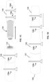
- FIGS. 1A-1E and FIG. 6 illustrate an exemplary method of assembling a single shell heat exchange module 100 ( FIG. 1D ).
- the heat exchange module 100 comprises a coil wound heat exchanger (CWHE).
- CWHEs are often employed for natural gas liquefaction.
- CWHEs typically contain helically wound tube bundles housed within an aluminum or stainless steel shell that forms a pressure vessel.
- LNG liquid natural gas
- a CWHE may include multiple tube bundles, each having several tube circuits.
- Cooling might be provided using any one of a variety of refrigerants, for example, a mixed refrigerant (MR) stream having a mixture of nitrogen, methane, ethane/ethylene, propane, butanes and pentanes is a commonly used refrigerant for many base-load LNG plants.
- the refrigeration cycle employed for natural gas liquefaction might be a cascade cycle, single mixed refrigerant cycle (SMR), propane-precooled mixed refrigerant cycle (C3MR), dual mixed refrigerant cycle (DMR), nitrogen or methane expander cycles, or any other appropriate refrigeration process.
- SMR single mixed refrigerant cycle
- C3MR propane-precooled mixed refrigerant cycle
- DMR dual mixed refrigerant cycle
- the composition of the MR stream is optimized for the feed gas composition and operating conditions.
- each tube bundle within the shell Located at the top of each tube bundle within the shell is a distributor assembly that distributes the refrigerant over the tube bundle in the space between the shell and the mandrel, which provides refrigeration for the fluids flowing through the tube bundles.
- a distributor assembly is disclosed in US Publication No. 2016/0209118 .
- FIGS. 1A-D illustrate a first exemplary method of assembling a heat exchange module 100 comprising a CWHE having two coil wound mandrels 114, 124.
- tubing 112 is spirally wound about a mandrel 110.
- multiple circuits of tubing will be wound about the mandrel 110.
- Each coil wound mandrel 114 has inlets located at or proximate to a first end 110a of the mandrel 110 and outlets located at or proximate to a second end 110b of the mandrel 110.
- two saddles 136a, 136b are affixed to a first (lower) portion 131 of the pressure vessel shell ("shell"), then the first coil wound mandrels 114 is telescoped (i.e., inserted) into the first portion 131 of the shell through an open top end of the first portion 131 along a longitudinal axis L of the lower portion 131.
- two saddles 136c and 136d affixed to a second (upper) portion 134 of the shell, then the second coil wound mandrel 124 is telescoped into the second portion 134.
- the first and second portions 131, 134 are joined to form the pressure vessel shell 132 (See FIG. 1D ).
- the shell 132 is transported to a plant site in a horizontal orientation (the orientation shown in FIG. 1D ).
- the heat exchange module 100 is erected into a vertical orientation and installation is completed.
- the module frame structure that supports the heat exchange module 100 at the plant site is not shown.
- the module frame is assembled and affixed to the first and second portions 131, 134 of the shell 130 prior to telescoping of the coil wound mandrels 114, 124.
- a key improvement of the assembly method described in connection with the heat exchange module 100 shown in FIGS. 1A-E is that the saddles 136a-136d are attached each portion 131, 134 of the shell 132 prior to telescoping the coil wound mandrel 114, 124 into each portion, that those saddles 136a-136d are never removed from the shell 132, and that the saddles 136a-136d are attached to the module frame when it is installed.
- the saddles 136a-d that are used to support the portions 131, 134 of the shell 132 during telescoping remain part of the structural support of the CWHE throughout the construction and installation process, as well as when the CWHE is operated.
- the saddles 136a-136d are adapted to provide support for the CWHE during transport (when it is in a horizonal orientation) and after the CWHE has been erected and installed at the plant site (in which the CWHE is in a vertical orientation). This is in contrast to conventional assembly methods, in which three different set of saddles are used in the telescoping, transportation, and final installation stages.
- each of saddles 136a-136b includes a frame portion (see frame portions 137a, 137b) that is framed around (i.e., fully encircles) the shell 132 and a base portion (see base portions 138a, 138b) that makes contact with a load bearing surface (e.g., a platform, ground, and/or a module frame) and supports horizontal and vertical loads when the shell 132 is in a horizontal orientation.
- a load bearing surface e.g., a platform, ground, and/or a module frame
- insulation can be installed on shell 132 prior to transportation of the CWHE to the plant site because it won't be disturbed by removal and installation of different saddles and additional connection to the module frame.
- FIGS. 2A-2C illustrate the exemplary assembly method on a heat exchange module 200 having a different configuration.
- This exemplary embodiment is very similar to the method described in FIGS. 1A-1E , the primary difference being that, in this exemplary embodiment, the CWHE has two separate shells (pressure vessels) 230, 240, each containing one coil wound mandrel 214.
- the coil wound mandrels are formed as shown in FIG. 1A .
- two saddles 236a, 236b are affixed to the first shell 230, then the first coil wound mandrel 210,214 is telescoped into the first shell 230 through an open top end/face.
- the top end of the shell 230 is sealed by, as shown in FIG. 2B .
- the process is repeated for the second shell 240.
- the assembled shells 230, 240 are transported to the plant site in the same manner as the shell 130 and as shown in FIG. 1D .
- each of the shells 230, 240 are erected into a vertical orientation.
- Two saddles 236c, 236d are affixed to the second shell 240.
- the module frame structure that supports the CWHE shells 230, 240 at the plant site is not shown.
- the module frame is assembled and affixed to the shells 230, 240 prior to telescoping of the coil wound mandrels.
- the CWHE comprises two shells 230, 240
- the second shell 240 is positioned atop the first shell 230.
- the module frame of the second shell 240 is preferably attached to the top of the module frame for the first shell 230.
- FIGS. 3A-3D illustrate another exemplary method of assembling a heat exchange module 300 having a multiple shell CWHE.
- the steps of the assembly process are nearly identical to those of the embodiment shown in FIGS. 2A-2C , except the module frames 360a-b are constructed and connected to the saddles 338a-b prior to telescoping the coil wound mandrels 310, 320 into the respective shells 330, 340 (see FIGS. 3A-C ).
- module frame 360a Constructing the module frame 360a and connecting the saddles 338a-b to the module frame 360a prior to telescoping enables external piping 354a-c, piping supports, valves, steps, ladders, standing platforms, and insulation to be installed prior to transportation of the shells 330, 340 to the plant site because the module frame 360a protects the shell 330 and provides attachment points for the elements being installed.
- the module frame 360a, the fully formed shell 330, and the saddles 336a-b form a heat exchange module 366a.
- a second heat exchange module 366b is formed using the same steps as the heat exchange module 366a.
- the first heat exchange module 366a is erected into a vertical position and the first module frame is affixed to a platform 361 at the plant site (typically a concrete pad or footer). Then the second heat exchange module 366b is erected into a vertical position and the second module frame 366b is mounted to top of the first module frame 366a.
- FIG. 3C illustrates another exemplary method for forming a heat exchange module 300.
- the multiple shell heat exchange module 300 includes two pressure vessels (shells) 330, 340, a first module frame 360a and a second module frame 360b are manufactured.
- Each module frame 360 includes a plurality of beams 362 and trusses 364 to increase the overall strength of the structure.
- the plurality of beams 362 define a frame volume of the module frame 360.
- Trusses 364, if included, may also define the frame volume since they do not extend beyond the frame volume defined by the beams 362.
- the framing of each module frame 360 forms a rectangular frame with a cavity (i.e., frame volume) configured to receive a corresponding pressure vessel.
- each module frame 360 is serves as an exoskeleton for its pressure vessel.
- Multiple module frames and support modules may be manufactured in parallel for each pressure vessel.
- the first and second module frames 360a, 360b are configured to be rigidly connected to a corresponding one of the first and second shells 330, 340, thereby forming a first heat exchange module.
- the plurality of beams 362 are sized and arranged such that no part of the pressure vessel shell extends outwardly beyond the frame volume.
- a pressure vessel including external piping and wiring is confined within the frame volume, while in other embodiments, some eternal piping and wiring may extend beyond the frame volume.
- the module frame 360 itself is a frame enclosure configured to enclose a pressure vessel therein, such that the module frame 360 defines an outermost boundary in each dimension of the corresponding pressure vessel shell. In other words, at the very least, the corresponding pressure vessel shell does not extend beyond the module frame 360 in any dimension.
- each of the first and second shells 330, 340 is suspended within the frame volume of its corresponding module frame, such that the pressure vessel is supported by the module frame both when in a horizonal orientation and in a vertical orientation.
- each saddle 136 is rigidly attached to its corresponding module frame 360 (see e.g., FIG. 3D ). Also, when the wound bundle 314 is being telescoped into the shell 330, it may be desirable to pull the wound bundle 314 through the shell 330 using cables that extend through a opening at the bottom end of the shell 330.
- FIGS. 4A-4H Another exemplary embodiment is shown in FIGS. 4A-4H .
- exemplary structures used to execute the assembly methods disclosed in FIGS. 1A-3D are disclosed in greater detail.
- FIGS. 4A-B show a fully assembled CWHE, which consists of two heat exchange modules 466a, 466b.
- Each heat exchange module 466a, 466b comprises a shell 430, 440, a module frame 460a, 460b, two saddles 436a-d, and a lug 441a, 441b.
- the saddles 436a-d, and the lug 441a, 441b connect the shells 430, 440 to their respective module frames 466a, 466b and are adapted to accommodate for multiple types of loads throughout the assembly process and during operation.
- the structure of the second heat exchange module 466b will be described in detail herein. The described structure is nearly identical in nature in the first heat exchange module 466a, understanding that some dimensions may be different due primarily to the fact that the shells 430, 440 have different dimensions.
- FIGS. 4C-E One of the saddles 436d is shown in FIGS. 4C-E .
- the saddle 436d includes a frame portion 437 which encircles the shell 440.
- the saddle 436d further includes sliding joint plates 438a-b which engage sliding joints 467a-d and connect the saddle 436d with a cross member 462 of the module frame 466d.
- a base plate 438 can be provided at the connection to the cross member 462 to provide additional structural strength.
- the saddle 436d further includes a contoured plate 472, which is arcuate and complimentary in shape to the outer surface of the shell 440 along an interface.
- the interface preferably overlaps at least one quarter and, more preferably, at least one third of the circumference of the shell 440.
- the saddle 436d further includes a plurality of ribs 439, which extend linearly from the base plate 438, are welded to the sliding joint plates 443a-b, then continue to the contour plate 472 in a direction that is perpendicular to the base plate 438.
- the saddle 436d is rigidly affixed to the shell 340, either with welds and or fasteners.
- Each of the sliding joints 467a-d includes a plurality of bolts 468 (in this embodiment, two bolts per sliding joint), which extend through slots 469 formed in the sliding joint plates 445a-b.
- Each slot 469 has a length that is significantly greater than the diameter of the bolt 468 that engages that slot 469.
- the length of the slot 469 is preferably at least 1.5 times (more preferably at least twice) the diameter of the bolt 468.
- an elongated slot 469 could be formed in one of the sliding joint plates 445a-b and holes that are much closer to the diameter of the bolts 468 could be provided.
- the joint plates 445a-b, slots 469, and bolts 468 combine to define a shear block.
- the configuration of the sliding joints 436a-d enables the saddle 436d to move relative to the module frame 466b in a direction parallel to the length of the shell 430, but prevents any other substantial movement of the saddle 436d relative to the module frame 466b.
- the movement allowed by the slots 469 is preferably sufficient to accommodate thermal contraction and expansion of the shell 440 that is expected to occur when the shell 440 is transition to operating temperature.
- FIGS. 4G-H show the structure of the lug 441b in detail.
- the lug 441b comprises cross-members 442a-d and beams 443a-d that "box" in the shell 440.
- the beams 443a-d are each welded to two cross-members 442a-d and are either welded or bolded to the shell 440.
- the cross-members 442a-d are also preferably welded or bolted to the module frame. This structure rigidly attaches the lug 441b to both the shell 440 and the module frame 460b.
- the lug 441b and the two saddles 436c-d attach the shell 440 to the module frame 460b and cooperate to accommodate multiple different types of loads during assembly, transportation, and operation of the heat exchange module 400.
- the saddles 436c-d provide the primary support and stability for the shell 440.
- the lug 441b provides the primary vertical support.
- the saddles 436c-d cooperate with the lug 441b to provide support against wind and seismic loads.
- the sliding joints 467a-d and the position of each saddle 436c-d allows for thermal expansion of the shell 440.
- the preferred location of the lug 441b and the saddles 436c-d will depend upon a number of factors, including the geometry of the shell 440, its position in the module frame 460b, and the location of piping protrusions on the surface of the shell 440. In general, it is preferable that the lug 441b be located within 5% (more preferably within 2%) of the center of mass of the shell 440.
- the lower saddle 436c is located between the lug 441b and the bottom end of the shell 440 and is preferably within 5% (more preferably within 2%) of the midpoint between the location of the lug 441b and the bottom end of the shell 440.
- the upper saddle 436c is located between the lug 441b and the top end of the shell 440 and is preferably within 5% (more preferably within 2%) of the midpoint between the location of the lug 441b and the top end of the shell 440.
- the lug 441b would be preferably located within 0.5 meters, and more preferably within 0.2 meters, of the midpoint.
- each shell 430, 440 is contained within a perimeter defined by the cross members 462a-d (see FIG. 4D ) of the module frame 466a-b. This provides protection for the shells 430,440 during construction and transport. It should be understood that a shell 430, 440 may extend beyond an end of the frame module 466a-b, such at the top of shell 430, which extends beyond the upper end of its frame module 466b. This most common for a shell of a single-shell heat exchanger or the uppermost shell of a multiple-shell heat exchanger.
- valves and instruments can be installed and insulated before the long lead bundles are telescoped into the shells. Additionally, this method can eliminate the need for temporary shipping saddles. In addition, the use of multiple pressure vessels including any combination thereof within the module frames can be accommodated. Furthermore, once at the operation site the final piping connections are made and the exchanger modules can be made operational.
- FIG. 5 An exemplary natural gas liquefaction system 2 is shown in FIG. 5 .
- a feed stream 1 which is preferably natural gas, is cleaned and dried by known methods in a pre-treatment section 7 to remove water, acid gases such as CO2 and H2S, and other contaminants such as mercury, resulting in a pre-treated feed stream 3.
- the pre-treated feed stream 3, which is essentially water free, is pre-cooled in a pre-cooling system 18 to produce a pre-cooled natural gas stream 5 and further cooled, liquefied, and/or sub-cooled in a CWHE 8 (which could be heat exchange module 100 or 200) to produce an LNG stream 6.
- the LNG stream 6 is typically let down in pressure by passing it through a valve or a turbine (not shown) and is then sent to LNG storage tank 9. Any flash vapor produced during the pressure letdown and/or boil-off in the tank is represented by stream 45, which may be used as fuel in the plant, recycled to feed, or vented.
- the pre-treated feed stream 1 is pre-cooled to a temperature below 10 degrees Celsius, preferably below about 0 degrees Celsius, and more preferably about -30 degrees Celsius.
- the pre-cooled natural gas stream 5 is liquefied to a temperature between about -150 degrees Celsius and about -70 degrees Celsius, preferably between about -145 degrees Celsius and about -100 degrees Celsius, and subsequently sub-cooled to a temperature between about -170 degrees Celsius and about -120 degrees Celsius, preferably between about -170 degrees Celsius and about -140 degrees Celsius.
- CWHE 8 is a coil wound heat exchanger with three bundles. However, any number of bundles and any exchanger type may be utilized.
- Refrigeration duty for the CWHE 8 is provided by a mixed refrigerant that is cooled and compressed in a compression system 31.
- the warm mixed refrigerant is withdrawn from the bottom of the CWHE 8 at stream 30, cooled and compressed, then reintroduced into the tube bundles through streams 41, 43.
- the mixed refrigerant is withdrawn, expanded, and reintroduced in the shell side of the CWHE 8 via streams 42, 44. Additional details concerning the natural gas liquefaction system can be found in US Publication No. 2018/0283774 .
- the system 2 shown in FIG. 5 is identical to the system shown in FIG. 1 of US Publication No. 2018/0283774 .
- the integration of the pressure containing shell (i.e., pressure vessel) into the module frame inclusive of piping outside as well as internal to the CWHE reduces manufacturing time, cost, and field work through simultaneous mechanical work and winding of the bundle.
- the wound bundle Once the wound bundle is completed it can be telescoped into the pressure shell that is already disposed within the module frame for final assembly.
- This method allows for completion of electrical and mechanical work, including both electrical systems and piping systems (both internal and external) within the module frame prior to completion of manufacturing of the mandrel with the wound bundle. It also allows for the manufacturing of the pressure shell and assembly to be completed at different sites to optimize labor availability and cost.
- saddles that are configured to support both horizontal and vertical loads of the pressure vessels aids in: performing the electrical and mechanical work on the pressure shell within the module frame, supporting the horizontal pressure vessel during shipping of the pressure vessel within the module frame, and supporting the erected pressure vessel within the module frame at the operation site, including during operation.
- FIG. 6 provides a flow diagram of an exemplary method of assembly, transport, and installation of a heat exchange module in accordance with the exemplary embodiments described herein.
- the process commences with construction of the shell (step 1012) and winding of tubes around the mandrel to form a wound bundle (step 1014).
- the module frame including the saddles and lug, is constructed (step 1016) and attached to the shell (step 1018).
- the wound bundle is finished, it is telescoped (inserted) into the shell (step 1022) and the top end of the shell is closed (step 1024).
- the heat exchange module can then be transferred to a transportation vehicle (step 1028), transported to the plant site (step 1030) and erected and installed at the plant site (step 1032).
- Constructing and attaching the module frame to the shell prior to telescoping the wound bundle into the shell provides a number of benefits.
- the structural stability of the module frame reduces stress on the shell during telescoping, transition to transportation, during transportation, and during erection of the shell at the plant side. In some applications, this will enable the shell to be thinner (and therefore lighter) and less costly.
- the bracing force used to stabilize the shell during the telescoping step 1022 can be applied to the module frame instead of being applied directly to the shell.
- the moving/lifting forces can be applied to the module frame instead of being applied directly to the shell.
- the upper shell e.g., shell 440 of FIG. 4A
- the lower shell e.g., shell 430 of FIG. 4A
- Constructing and attaching the module frame to the shell prior to telescoping also enables some process steps that are required to be performed in series using conventional methods to be performed in parallel.
- piping penetrations, piping, piping supports, electrical connections, instrumentation, and insulation, etc. can be installed on the shell (step 1020) prior to or in parallel with the telescoping step 1022.
- these elements could not be installed until after the shell is installed at the plant site.
- This improvement not only shortens the overall process length, it also enables additional process steps to be performed in an indoor environment instead of being performed outdoors at a plant site.
- it enables the option to pressure test the shell (step 1026) under shop conditions and before transport to the plant site (step 1030).
Landscapes
- Engineering & Computer Science (AREA)
- Mechanical Engineering (AREA)
- Physics & Mathematics (AREA)
- Thermal Sciences (AREA)
- General Engineering & Computer Science (AREA)
- Chemical & Material Sciences (AREA)
- Chemical Kinetics & Catalysis (AREA)
- General Chemical & Material Sciences (AREA)
- Oil, Petroleum & Natural Gas (AREA)
- Heat-Exchange Devices With Radiators And Conduit Assemblies (AREA)
- Separation By Low-Temperature Treatments (AREA)
Claims (16)
- Verfahren, das Folgendes umfasst:(a) Bilden eines ersten Dorns (110, 310);(b) Bilden eines ersten gewickelten Bündels auf dem ersten Dorn, um einen ersten spulengewickelten Dorn (114, 314) durch Wickeln eines Schlauches (112) um den ersten Dorn (110, 310) zu bilden;(c) Bereitstellen eines ersten Abschnitts (131) eines ersten Wärmetauschermantels (130, 330, 340, 430, 440), wobei der erste Abschnitt eine erste offene Fläche und eine erste Mantellängsachse (L) aufweist, die sich parallel zu einer größten Abmessung des ersten Wärmetauschermantels erstreckt;(d) Befestigen des ersten Abschnitts (131) des ersten Wärmetauschermantels (130, 330, 430, 440) an einem ersten Modulrahmen (360a-b, 460) mit mindestens zwei Verbindungselementen (336a-d, 436a-d, 441a-b), die starr am ersten Wärmetauschermantel befestigt sind, um ein erstes Wärmetauschermodul (366a-b, 466a-b) zu bilden, wobei der erste Modulrahmen eine Vielzahl von Säulen, die durch Querträger verbunden sind, umfasst;(e) nach dem Durchführen von Schritt (d), Teleskopieren des ersten spulengewickelten Dorns (114, 314) in den ersten Abschnitt (131) des ersten Wärmetauschermantels (130, 330, 340, 430, 440) durch die erste offene Fläche, während die erste Mantellängsachse (L) in einer im Wesentlichen horizontalen Ausrichtung ist;(f) nach dem Durchführen von Schritt (e), Schließen der ersten offenen Fläche des ersten Wärmetauschermantels (130, 330, 340, 430, 440);(g) nach dem Durchführen von Schritt (f), Transportieren des ersten Wärmetauschermoduls (366a-b, 466a-b) zu einem Anlagenstandort; und(h) nach dem Durchführen von Schritt (g), Montieren des ersten Wärmetauschermoduls (366a-b, 466a-b) am Anlagenstandort mit der ersten Mantellängsachse (L) in einer im Wesentlichen vertikalen Ausrichtung, wobei das erste Wärmetauschermodul in einer festen Position innerhalb des ersten Modulrahmens (360a-b, 460) durch die mindestens zwei Verbindungselemente (336a-d, 436a-d, 441a-b) aufgehängt ist.
- Verfahren nach Anspruch 1, wobei die mindestens zwei Verbindungselemente mindestens einen Sattel (336a-d, 436a-d) umfassen und Schritt (d) ferner das Verbinden des mindestens einen Sattels mit dem ersten Modulrahmen (360a-b, 460) mit einer Vielzahl von Gelenken (467a-d) umfasst, die es dem mindestens einen Sattel ermöglichen, sich relativ zu dem ersten Modulrahmen in einer Richtung zu bewegen, die parallel zu der ersten Mantellängsachse (L) verläuft, während eine Bewegung des mindestens einen Sattels relativ zum ersten Modulrahmen in Richtungen, die nicht parallel zur ersten Mantellängsachse verlaufen, verhindert wird.
- Verfahren nach Anspruch 1, wobei die mindestens zwei Verbindungselemente mindestens zwei Sättel (336a-d, 436a-d) umfassen und Schritt (d) ferner das Verbinden der mindestens zwei Sättel mit dem ersten Modulrahmen (360a-b, 460) mit einer Vielzahl von Gelenken (467a-d) umfasst, die es jedem der mindestens zwei Sättel ermöglichen, sich relativ zu dem ersten Modulrahmen in einer Richtung zu bewegen, die parallel zu der ersten Mantellängsachse (L) verläuft, während eine Bewegung jedes der mindestens zwei Sättel relativ zum ersten Modulrahmen in Richtungen, die nicht parallel zur ersten Mantellängsachse verlaufen, verhindert wird.
- Verfahren nach einem der Ansprüche 1 bis 3, wobei die mindestens zwei Verbindungselemente mindestens eine Lasche (441a-b) umfassen und Schritt (d) ferner das starre Befestigen der mindestens einen Lasche an dem ersten Modulrahmen (360a-b, 460) umfasst.
- Verfahren nach einem der Ansprüche 1 bis 4, das ferner Folgendes umfasst:(i) vor dem Durchführen von Schritt (g), Installieren von mindestens einem aus der Gruppe der folgenden Elemente auf dem ersten Wärmetauschermodul (366a-b, 466a-b): Rohrleitungen (354a-d), Rohrleitungshalterungen, Ventilen, Instrumentierung, elektrischen Systemen, Stufen, Leitern, Stehpodesten und Isolierung.
- Verfahren nach einem der Ansprüche 1 bis 4, das ferner Folgendes umfasst:
(j) vor dem Durchführen von Schritt (g), Installieren von mindestens einem aus der Gruppe der folgenden Elemente auf dem ersten Wärmetauschermodul (366a-b, 466a-b): Rohrleitungen (354a-d), Rohrleitungshalterungen, Ventilen, Stufen, Leitern, Stehpodesten und Isolierung. - Verfahren nach Anspruch 5, das ferner das Durchführen von Schritt (i) vor Abschluss von Schritt (e) umfasst.
- Verfahren nach einem der Ansprüche 1 bis 7, das ferner Folgendes umfasst:
(k) vor dem Durchführen von Schritt (g), Isolieren einer Außenfläche des ersten Wärmetauschermoduls (366a-b, 466a-b). - Verfahren nach einem der Ansprüche 1 bis 8, wobei der Schritt (h) das starre Befestigen des ersten Modulrahmens (360a-b, 460) an einer Plattform am Anlagenstandort (361) umfasst.
- Verfahren nach einem der Ansprüche 1 bis 9, wobei der Schritt (d) ferner das Konfigurieren des ersten Modulrahmens (360a-b, 460) umfasst, um den befestigten ersten Abschnitt (131) des ersten Wärmetauschermantels (130, 330, 340, 430, 440) innerhalb eines Rahmenumfangs zu enthalten, der durch die Vielzahl von Säulen des ersten Wärmetauschermoduls definiert ist.
- Verfahren nach einem der Ansprüche 1 bis 10, das ferner Folgendes umfasst:(l) Bereitstellen einer Kabelöffnung in dem ersten Wärmetauschermantel (130, 330, 340, 430, 440) an einem Ende, das sich distal zur ersten offenen Fläche befindet, und Durchleiten eines Kabels durch die Kabelöffnung;wobei der Schritt (e) ferner das Einziehen des ersten spulengewickelten Dorns (114, 314) in den ersten Wärmetauschermantel (130, 330, 340, 430, 440) unter Verwendung des Kabels während zumindest eines Abschnitts von Schritt (e) umfasst.
- Verfahren nach einem der Ansprüche 1 bis 11, das ferner Folgendes umfasst:(m) Wiederholen der Schritte (a) bis (f) zur Bildung eines zweiten Wärmetauschermoduls (366b, 466b);(n) nach dem Durchführen von Schritt (m), Transportieren des zweiten Wärmetauschermoduls zu einem Anlagenstandort (366b, 466b); und(o) nach dem Durchführen von Schritt (n), Montieren des zweiten Wärmetauschermoduls (366b, 466b) auf dem ersten Wärmetauschermodul (366a, 466a) am Anlagenstandort mit einer zweiten Mantellängsachse des zweiten Wärmetauschermoduls in einer im Wesentlichen vertikalen Ausrichtung, wobei das zweite Wärmetauschermodul innerhalb eines zweiten Modulrahmens (360b, 460) des zweiten Wärmetauschermoduls durch die mindestens zwei Verbindungselemente (336a-d, 436a-d, 441a-b) in einer festen Position aufgehängt ist.
- Verfahren nach Anspruch 12, das ferner Folgendes umfasst:
(p) Installieren mindestens einer Leitung, die eine Fluidstromverbindung zwischen dem Mantel (330, 430) des ersten Wärmetauschermoduls (366a, 466a) und dem Mantel (340, 440) des zweiten Wärmetauschermoduls (366b, 466b) herstellt. - Verfahren nach einem der Ansprüche 1 bis 13, das ferner Folgendes umfasst:
(q) während des Durchführens von Schritt (e), Verspannen des ersten Wärmetauschermantels (330, 340, 430, 440) gegen eine auf den ersten Wärmetauschermantel (130, 330, 340, 430, 440) ausgeübte Kraft durch das Teleskopieren des ersten spulengewickelten Dorns (114, 314) allein durch Aufbringen einer Verspannungskraft auf den ersten Modulrahmen. - Verfahren nach einem der Ansprüche 1 bis 14, das ferner Folgendes umfasst:
(r) Druckprüfen des ersten Wärmetauschermantels (130, 330, 340, 430, 440) vor dem Durchführen von Schritt (g). - Verfahren nach einem der Ansprüche 1 bis 15, das ferner Folgendes umfasst:(s) Bilden eines zweiten Dorns;(t) Bilden eines zweiten spulengewickelten Dorns (124) durch Wickeln von einem Schlauch um den zweiten Dorn;(u) Bereitstellen eines zweiten Abschnitts (134) des ersten Wärmetauschermantels (130), wobei der zweite Abschnitt eine zweite offene Fläche und eine zweite Mantellängsachse aufweist, die sich parallel zur größten Abmessung des zweiten Wärmetauschermantels erstreckt;(v) Befestigen des zweiten Abschnitts (134) des ersten Wärmetauschermantels (130) an einem zweiten Modulrahmen (360b) mit mindestens zwei Verbindungselementen (336c-d, 436c-d, 441b), die starr an dem zweiten Abschnitt des ersten Wärmetauschermantels befestigt sind, wobei der erste Modulrahmen eine Vielzahl von Säulen umfasst, die durch Querträger verbunden sind; und(w) Teleskopieren des zweiten spulengewickelten Dorns (124) in den zweiten Abschnitt (134) des ersten Wärmetauschermantels (130) durch die zweite offene Fläche, während die zweite Mantellängsachse in einer im Wesentlichen horizontalen Ausrichtung ist;wobei der Schritt (f) nach dem Durchführen der Schritte (e) und (w) das Schließen der ersten offenen Fläche des ersten Wärmetauschermantels (130) durch Verbinden des ersten Abschnitts (131) des ersten Wärmetauschermantels (130) mit dem zweiten Abschnitt (134) des ersten Wärmetauschermantels und Verbinden des ersten Modulrahmens (360a) mit dem zweiten Modulrahmen (360b) zum Bilden des ersten Wärmetauschermoduls (366a-b) umfasst.
Priority Applications (1)
| Application Number | Priority Date | Filing Date | Title |
|---|---|---|---|
| EP22211356.5A EP4166877B1 (de) | 2019-10-08 | 2020-10-08 | Wärmeaustauschsystem und montageverfahren |
Applications Claiming Priority (2)
| Application Number | Priority Date | Filing Date | Title |
|---|---|---|---|
| US201962912246P | 2019-10-08 | 2019-10-08 | |
| PCT/US2020/054794 WO2021072082A1 (en) | 2019-10-08 | 2020-10-08 | Heat exchange system and method of assembly |
Related Child Applications (2)
| Application Number | Title | Priority Date | Filing Date |
|---|---|---|---|
| EP22211356.5A Division EP4166877B1 (de) | 2019-10-08 | 2020-10-08 | Wärmeaustauschsystem und montageverfahren |
| EP22211356.5A Division-Into EP4166877B1 (de) | 2019-10-08 | 2020-10-08 | Wärmeaustauschsystem und montageverfahren |
Publications (3)
| Publication Number | Publication Date |
|---|---|
| EP4042082A1 EP4042082A1 (de) | 2022-08-17 |
| EP4042082B1 true EP4042082B1 (de) | 2024-10-23 |
| EP4042082B8 EP4042082B8 (de) | 2024-12-04 |
Family
ID=73040257
Family Applications (2)
| Application Number | Title | Priority Date | Filing Date |
|---|---|---|---|
| EP20800402.8A Active EP4042082B8 (de) | 2019-10-08 | 2020-10-08 | Wärmetauschersystem und verfahren zur montage |
| EP22211356.5A Active EP4166877B1 (de) | 2019-10-08 | 2020-10-08 | Wärmeaustauschsystem und montageverfahren |
Family Applications After (1)
| Application Number | Title | Priority Date | Filing Date |
|---|---|---|---|
| EP22211356.5A Active EP4166877B1 (de) | 2019-10-08 | 2020-10-08 | Wärmeaustauschsystem und montageverfahren |
Country Status (10)
| Country | Link |
|---|---|
| US (3) | US11187467B2 (de) |
| EP (2) | EP4042082B8 (de) |
| CN (1) | CN114555258B (de) |
| AU (1) | AU2020363817B2 (de) |
| CA (1) | CA3151989C (de) |
| ES (2) | ES2999637T3 (de) |
| MX (3) | MX2022002972A (de) |
| PE (1) | PE20220677A1 (de) |
| PL (2) | PL4166877T3 (de) |
| WO (1) | WO2021072082A1 (de) |
Families Citing this family (2)
| Publication number | Priority date | Publication date | Assignee | Title |
|---|---|---|---|---|
| FR3099815B1 (fr) * | 2019-08-05 | 2021-09-10 | Air Liquide | Dispositif et installation de réfrigération |
| US20240375226A1 (en) * | 2023-05-09 | 2024-11-14 | Air Products And Chemicals, Inc. | Apparatus and Method for Horizontal Transport and Vertical Installation of Heat Exchanger |
Family Cites Families (38)
| Publication number | Priority date | Publication date | Assignee | Title |
|---|---|---|---|---|
| US3126103A (en) * | 1964-03-24 | Connector for tube bundle extractor | ||
| US2475109A (en) * | 1945-08-06 | 1949-07-05 | Phillips Ptroleum Company | Floating heat exchanger support |
| US2615687A (en) | 1948-01-03 | 1952-10-28 | American Blower Corp | Heat exchanger |
| US3239076A (en) * | 1957-06-17 | 1966-03-08 | Texaco Inc | Apparatus for moving heat exchanger tube bundles |
| US3239077A (en) * | 1957-11-21 | 1966-03-08 | Texaco Inc | Apparatus for moving heat exchanger tube bundles |
| US3257001A (en) * | 1957-12-23 | 1966-06-21 | Chevron Res | Tube bundle extractor |
| US3048280A (en) * | 1958-05-09 | 1962-08-07 | Texaco Inc | Apparatus for removing heat exchanger tube bundles |
| US3075664A (en) * | 1960-02-18 | 1963-01-29 | Alfred C Body | Device for handling hollow cylindrical articles |
| US3180498A (en) * | 1961-10-02 | 1965-04-27 | California Research Corp | Tube bundle extractor for heat exchangers |
| US3510012A (en) * | 1968-08-15 | 1970-05-05 | Lummus Co | Tube bundle handling apparatus |
| US3567044A (en) * | 1968-09-03 | 1971-03-02 | Bobby J Travis | Apparatus for force application |
| US3658191A (en) * | 1970-12-14 | 1972-04-25 | Thomas V Murphy | Crane for extracting horizontally-aligned relatively-long tube bundles |
| US3765544A (en) * | 1972-08-16 | 1973-10-16 | T Murphy | Crane for extracting horizontal long tube bundles |
| NL7307086A (de) * | 1973-05-21 | 1974-11-25 | ||
| NL7307083A (de) * | 1973-05-21 | 1974-11-25 | ||
| US3935951A (en) * | 1974-07-26 | 1976-02-03 | Ulrich Claus | Apparatus for pulling and replacing heat exchange tubing |
| NO150237C (no) * | 1977-07-11 | 1984-09-12 | Ici Ltd | Anordning til aa skyve en roerbunt ut av eller inn i mantelen til en varmeveksler |
| US4192053A (en) * | 1977-09-19 | 1980-03-11 | Westinghouse Electric Corp. | Method for retubing a steam generator |
| US4346759A (en) | 1978-04-10 | 1982-08-31 | Aerco International, Inc. | Heat reclaiming system |
| US4199857A (en) * | 1978-05-01 | 1980-04-29 | Westinghouse Electric Corp. | Tube bundle removal method and apparatus |
| US4323398A (en) * | 1980-04-07 | 1982-04-06 | Andrew Simon | Performing maintenance operations on heat exchanger tube bundles |
| DE3146659A1 (de) | 1981-11-25 | 1983-06-23 | Gebrüder Uhl GmbH & Co KG, 7981 Vogt | "einrichtung zur uebertragung von waermeenergie" |
| US4869638A (en) * | 1987-11-04 | 1989-09-26 | Serv-Tech, Inc. | Aerial bundle puller |
| US5032054A (en) * | 1987-11-04 | 1991-07-16 | Serv-Tech, Inc. | Aerial bundle puller |
| US4970867A (en) | 1989-08-21 | 1990-11-20 | Air Products And Chemicals, Inc. | Liquefaction of natural gas using process-loaded expanders |
| US5188170A (en) | 1992-09-09 | 1993-02-23 | Giberson Melbourne F | Rocker connection |
| FR2703762B1 (fr) * | 1993-04-09 | 1995-05-24 | Maurice Grenier | Procédé et installation de refroidissement d'un fluide, notamment pour la liquéfaction de gaz naturel. |
| FR2775439B1 (fr) | 1997-10-14 | 2000-04-14 | Air Liquide | Procede de construction d'une structure interieure de confinement de fluide allongee, de grandes dimensions, et entouree d'une structure exterieure |
| ATE311580T1 (de) | 2002-05-27 | 2005-12-15 | Air Prod & Chem | Wärmetauscher mit gewickelten rohrschlangen |
| PT2161525T (pt) * | 2008-09-08 | 2016-07-26 | Balcke-Dürr GmbH | Permutador de calor de construção modular |
| KR101962996B1 (ko) * | 2012-01-12 | 2019-07-31 | 웨스팅하우스 일렉트릭 컴퍼니 엘엘씨 | 모듈형 플레이트 및 쉘 열 교환기 |
| US9528777B2 (en) * | 2012-06-29 | 2016-12-27 | Dana Canada Corporation | Heat exchangers with floating headers |
| KR101764391B1 (ko) * | 2014-03-17 | 2017-08-03 | 콘데보 에스.피.에이. | 열 교환 셀 및 방법 |
| US20160209118A1 (en) | 2015-01-16 | 2016-07-21 | Air Products And Chemicals, Inc. | Shell-Side Fluid Distribution in Coil Wound Heat Exchangers |
| DE102016002621A1 (de) * | 2016-03-07 | 2017-09-07 | Modine Manufacturing Company | Multifunktionelle Grundplatte eines Wärmeübertragers |
| EP3246647B1 (de) * | 2016-05-19 | 2019-10-30 | Borgwarner Emissions Systems Spain, S.L.U. | Wärmetauschervorrichtung |
| US10544986B2 (en) | 2017-03-29 | 2020-01-28 | Air Products And Chemicals, Inc. | Parallel compression in LNG plants using a double flow compressor |
| CN110709660B (zh) * | 2017-04-12 | 2022-04-19 | 乔治洛德方法研究和开发液化空气有限公司 | 用于构造冷箱模块的方法和所得设备 |
-
2020
- 2020-10-08 EP EP20800402.8A patent/EP4042082B8/de active Active
- 2020-10-08 MX MX2022002972A patent/MX2022002972A/es unknown
- 2020-10-08 PE PE2022000416A patent/PE20220677A1/es unknown
- 2020-10-08 ES ES20800402T patent/ES2999637T3/es active Active
- 2020-10-08 EP EP22211356.5A patent/EP4166877B1/de active Active
- 2020-10-08 PL PL22211356.5T patent/PL4166877T3/pl unknown
- 2020-10-08 ES ES22211356T patent/ES3033311T3/es active Active
- 2020-10-08 CN CN202080070854.0A patent/CN114555258B/zh active Active
- 2020-10-08 CA CA3151989A patent/CA3151989C/en active Active
- 2020-10-08 WO PCT/US2020/054794 patent/WO2021072082A1/en not_active Ceased
- 2020-10-08 AU AU2020363817A patent/AU2020363817B2/en active Active
- 2020-10-08 PL PL20800402.8T patent/PL4042082T3/pl unknown
- 2020-10-08 US US17/274,363 patent/US11187467B2/en active Active
-
2021
- 2021-03-09 US US17/196,609 patent/US11391512B2/en active Active
-
2022
- 2022-03-10 MX MX2023005777A patent/MX2023005777A/es unknown
- 2022-03-10 MX MX2023005776A patent/MX2023005776A/es unknown
- 2022-06-09 US US17/836,063 patent/US11859903B2/en active Active
Also Published As
| Publication number | Publication date |
|---|---|
| MX2023005777A (es) | 2023-05-29 |
| ES3033311T3 (en) | 2025-08-01 |
| US20210333050A1 (en) | 2021-10-28 |
| PE20220677A1 (es) | 2022-04-29 |
| ES2999637T3 (en) | 2025-02-26 |
| AU2020363817B2 (en) | 2024-04-18 |
| CN114555258A (zh) | 2022-05-27 |
| EP4166877A1 (de) | 2023-04-19 |
| MX2022002972A (es) | 2022-04-06 |
| US11187467B2 (en) | 2021-11-30 |
| EP4042082A1 (de) | 2022-08-17 |
| CA3151989A1 (en) | 2021-04-15 |
| PL4042082T3 (pl) | 2025-05-12 |
| US11859903B2 (en) | 2024-01-02 |
| CN114555258B (zh) | 2023-04-18 |
| EP4042082B8 (de) | 2024-12-04 |
| US20220299263A1 (en) | 2022-09-22 |
| AU2020363817A1 (en) | 2022-05-26 |
| CA3151989C (en) | 2023-04-11 |
| WO2021072082A1 (en) | 2021-04-15 |
| MX2023005776A (es) | 2023-05-29 |
| PL4166877T3 (pl) | 2025-10-20 |
| US20210190419A1 (en) | 2021-06-24 |
| US11391512B2 (en) | 2022-07-19 |
| EP4166877B1 (de) | 2025-05-21 |
Similar Documents
| Publication | Publication Date | Title |
|---|---|---|
| US10539361B2 (en) | Modular LNG production facility | |
| RU2758296C1 (ru) | Структурная система модульной технологической установки | |
| US11859903B2 (en) | Heat exchange system and method of assembly | |
| US10060670B2 (en) | Air-cooled modular LNG production facility | |
| US6250244B1 (en) | Liquefaction apparatus | |
| RU2727948C1 (ru) | Модуль для устройств сжижения природного газа, устройство сжижения природного газа и способ производства устройств сжижения природного газа | |
| US9927170B2 (en) | Heat exchanger system | |
| AU2013202033A1 (en) | Modular lng production facility | |
| CA3092669C (en) | Modular process plant structural system | |
| US20230235954A1 (en) | Modular mid-scale liquefied natural gas production system and method | |
| CN109676367A (zh) | 一种热交换器组件及装配所述热交换器组件的方法 | |
| WO2020075295A1 (ja) | 天然ガス液化装置 |
Legal Events
| Date | Code | Title | Description |
|---|---|---|---|
| STAA | Information on the status of an ep patent application or granted ep patent |
Free format text: STATUS: UNKNOWN |
|
| STAA | Information on the status of an ep patent application or granted ep patent |
Free format text: STATUS: THE INTERNATIONAL PUBLICATION HAS BEEN MADE |
|
| PUAI | Public reference made under article 153(3) epc to a published international application that has entered the european phase |
Free format text: ORIGINAL CODE: 0009012 |
|
| STAA | Information on the status of an ep patent application or granted ep patent |
Free format text: STATUS: REQUEST FOR EXAMINATION WAS MADE |
|
| 17P | Request for examination filed |
Effective date: 20220506 |
|
| AK | Designated contracting states |
Kind code of ref document: A1 Designated state(s): AL AT BE BG CH CY CZ DE DK EE ES FI FR GB GR HR HU IE IS IT LI LT LU LV MC MK MT NL NO PL PT RO RS SE SI SK SM TR |
|
| DAV | Request for validation of the european patent (deleted) | ||
| DAX | Request for extension of the european patent (deleted) | ||
| STAA | Information on the status of an ep patent application or granted ep patent |
Free format text: STATUS: EXAMINATION IS IN PROGRESS |
|
| 17Q | First examination report despatched |
Effective date: 20230328 |
|
| GRAP | Despatch of communication of intention to grant a patent |
Free format text: ORIGINAL CODE: EPIDOSNIGR1 |
|
| STAA | Information on the status of an ep patent application or granted ep patent |
Free format text: STATUS: GRANT OF PATENT IS INTENDED |
|
| INTG | Intention to grant announced |
Effective date: 20240226 |
|
| GRAS | Grant fee paid |
Free format text: ORIGINAL CODE: EPIDOSNIGR3 |
|
| GRAA | (expected) grant |
Free format text: ORIGINAL CODE: 0009210 |
|
| STAA | Information on the status of an ep patent application or granted ep patent |
Free format text: STATUS: THE PATENT HAS BEEN GRANTED |
|
| AK | Designated contracting states |
Kind code of ref document: B1 Designated state(s): AL AT BE BG CH CY CZ DE DK EE ES FI FR GB GR HR HU IE IS IT LI LT LU LV MC MK MT NL NO PL PT RO RS SE SI SK SM TR |
|
| REG | Reference to a national code |
Ref country code: GB Ref legal event code: FG4D |
|
| REG | Reference to a national code |
Ref country code: CH Ref legal event code: EP |
|
| REG | Reference to a national code |
Ref country code: DE Ref legal event code: R096 Ref document number: 602020039976 Country of ref document: DE |
|
| REG | Reference to a national code |
Ref country code: CH Ref legal event code: PK Free format text: BERICHTIGUNG B8 |
|
| REG | Reference to a national code |
Ref country code: IE Ref legal event code: FG4D |
|
| P01 | Opt-out of the competence of the unified patent court (upc) registered |
Free format text: CASE NUMBER: APP_57826/2024 Effective date: 20241023 |
|
| RAP2 | Party data changed (patent owner data changed or rights of a patent transferred) |
Owner name: HERCULES PROJECT COMPANY LLC |
|
| REG | Reference to a national code |
Ref country code: NL Ref legal event code: FP |
|
| REG | Reference to a national code |
Ref country code: DE Ref legal event code: R081 Ref document number: 602020039976 Country of ref document: DE Owner name: HERCULES PROJECT COMPANY LLC, ALLENTOWN, US Free format text: FORMER OWNER: AIR PRODUCTS AND CHEMICALS, INC., ALLENTOWN, PA, US Ref country code: DE Ref legal event code: R081 Ref document number: 602020039976 Country of ref document: DE Owner name: HONEYWELL LNG LLC (N.D.GES.D.STAATES DELAWARE), US Free format text: FORMER OWNER: AIR PRODUCTS AND CHEMICALS, INC., ALLENTOWN, PA, US |
|
| REG | Reference to a national code |
Ref country code: LT Ref legal event code: MG9D |
|
| REG | Reference to a national code |
Ref country code: ES Ref legal event code: FG2A Ref document number: 2999637 Country of ref document: ES Kind code of ref document: T3 Effective date: 20250226 Ref country code: GB Ref legal event code: 732E Free format text: REGISTERED BETWEEN 20250130 AND 20250205 |
|
| REG | Reference to a national code |
Ref country code: AT Ref legal event code: MK05 Ref document number: 1735163 Country of ref document: AT Kind code of ref document: T Effective date: 20241023 |
|
| PG25 | Lapsed in a contracting state [announced via postgrant information from national office to epo] |
Ref country code: PT Free format text: LAPSE BECAUSE OF FAILURE TO SUBMIT A TRANSLATION OF THE DESCRIPTION OR TO PAY THE FEE WITHIN THE PRESCRIBED TIME-LIMIT Effective date: 20250224 Ref country code: HR Free format text: LAPSE BECAUSE OF FAILURE TO SUBMIT A TRANSLATION OF THE DESCRIPTION OR TO PAY THE FEE WITHIN THE PRESCRIBED TIME-LIMIT Effective date: 20241023 Ref country code: IS Free format text: LAPSE BECAUSE OF FAILURE TO SUBMIT A TRANSLATION OF THE DESCRIPTION OR TO PAY THE FEE WITHIN THE PRESCRIBED TIME-LIMIT Effective date: 20250223 |
|
| PG25 | Lapsed in a contracting state [announced via postgrant information from national office to epo] |
Ref country code: FI Free format text: LAPSE BECAUSE OF FAILURE TO SUBMIT A TRANSLATION OF THE DESCRIPTION OR TO PAY THE FEE WITHIN THE PRESCRIBED TIME-LIMIT Effective date: 20241023 |
|
| PG25 | Lapsed in a contracting state [announced via postgrant information from national office to epo] |
Ref country code: BG Free format text: LAPSE BECAUSE OF FAILURE TO SUBMIT A TRANSLATION OF THE DESCRIPTION OR TO PAY THE FEE WITHIN THE PRESCRIBED TIME-LIMIT Effective date: 20241023 |
|
| PG25 | Lapsed in a contracting state [announced via postgrant information from national office to epo] |
Ref country code: LV Free format text: LAPSE BECAUSE OF FAILURE TO SUBMIT A TRANSLATION OF THE DESCRIPTION OR TO PAY THE FEE WITHIN THE PRESCRIBED TIME-LIMIT Effective date: 20241023 Ref country code: GR Free format text: LAPSE BECAUSE OF FAILURE TO SUBMIT A TRANSLATION OF THE DESCRIPTION OR TO PAY THE FEE WITHIN THE PRESCRIBED TIME-LIMIT Effective date: 20250124 Ref country code: AT Free format text: LAPSE BECAUSE OF FAILURE TO SUBMIT A TRANSLATION OF THE DESCRIPTION OR TO PAY THE FEE WITHIN THE PRESCRIBED TIME-LIMIT Effective date: 20241023 |
|
| PG25 | Lapsed in a contracting state [announced via postgrant information from national office to epo] |
Ref country code: RS Free format text: LAPSE BECAUSE OF FAILURE TO SUBMIT A TRANSLATION OF THE DESCRIPTION OR TO PAY THE FEE WITHIN THE PRESCRIBED TIME-LIMIT Effective date: 20250123 |
|
| PG25 | Lapsed in a contracting state [announced via postgrant information from national office to epo] |
Ref country code: SM Free format text: LAPSE BECAUSE OF FAILURE TO SUBMIT A TRANSLATION OF THE DESCRIPTION OR TO PAY THE FEE WITHIN THE PRESCRIBED TIME-LIMIT Effective date: 20241023 |
|
| PG25 | Lapsed in a contracting state [announced via postgrant information from national office to epo] |
Ref country code: DK Free format text: LAPSE BECAUSE OF FAILURE TO SUBMIT A TRANSLATION OF THE DESCRIPTION OR TO PAY THE FEE WITHIN THE PRESCRIBED TIME-LIMIT Effective date: 20241023 |
|
| PG25 | Lapsed in a contracting state [announced via postgrant information from national office to epo] |
Ref country code: RO Free format text: LAPSE BECAUSE OF FAILURE TO SUBMIT A TRANSLATION OF THE DESCRIPTION OR TO PAY THE FEE WITHIN THE PRESCRIBED TIME-LIMIT Effective date: 20241023 |
|
| REG | Reference to a national code |
Ref country code: DE Ref legal event code: R097 Ref document number: 602020039976 Country of ref document: DE |
|
| PG25 | Lapsed in a contracting state [announced via postgrant information from national office to epo] |
Ref country code: SK Free format text: LAPSE BECAUSE OF FAILURE TO SUBMIT A TRANSLATION OF THE DESCRIPTION OR TO PAY THE FEE WITHIN THE PRESCRIBED TIME-LIMIT Effective date: 20241023 |
|
| PG25 | Lapsed in a contracting state [announced via postgrant information from national office to epo] |
Ref country code: CZ Free format text: LAPSE BECAUSE OF FAILURE TO SUBMIT A TRANSLATION OF THE DESCRIPTION OR TO PAY THE FEE WITHIN THE PRESCRIBED TIME-LIMIT Effective date: 20241023 |
|
| PLBE | No opposition filed within time limit |
Free format text: ORIGINAL CODE: 0009261 |
|
| STAA | Information on the status of an ep patent application or granted ep patent |
Free format text: STATUS: NO OPPOSITION FILED WITHIN TIME LIMIT |
|
| PG25 | Lapsed in a contracting state [announced via postgrant information from national office to epo] |
Ref country code: SE Free format text: LAPSE BECAUSE OF FAILURE TO SUBMIT A TRANSLATION OF THE DESCRIPTION OR TO PAY THE FEE WITHIN THE PRESCRIBED TIME-LIMIT Effective date: 20241023 |
|
| PGFP | Annual fee paid to national office [announced via postgrant information from national office to epo] |
Ref country code: NL Payment date: 20250826 Year of fee payment: 6 |
|
| 26N | No opposition filed |
Effective date: 20250724 |
|
| PGFP | Annual fee paid to national office [announced via postgrant information from national office to epo] |
Ref country code: IT Payment date: 20250922 Year of fee payment: 6 Ref country code: TR Payment date: 20250924 Year of fee payment: 6 Ref country code: PL Payment date: 20250829 Year of fee payment: 6 |
|
| PGFP | Annual fee paid to national office [announced via postgrant information from national office to epo] |
Ref country code: GB Payment date: 20250821 Year of fee payment: 6 |
|
| PGFP | Annual fee paid to national office [announced via postgrant information from national office to epo] |
Ref country code: FR Payment date: 20250821 Year of fee payment: 6 |
|
| REG | Reference to a national code |
Ref country code: DE Ref legal event code: R081 Ref document number: 602020039976 Country of ref document: DE Owner name: HONEYWELL LNG LLC (N.D.GES.D.STAATES DELAWARE), US Free format text: FORMER OWNER: HERCULES PROJECT COMPANY LLC, ALLENTOWN, PA, US |
|
| PGFP | Annual fee paid to national office [announced via postgrant information from national office to epo] |
Ref country code: DE Payment date: 20250819 Year of fee payment: 6 |
|
| PGFP | Annual fee paid to national office [announced via postgrant information from national office to epo] |
Ref country code: NO Payment date: 20251009 Year of fee payment: 6 |
|
| REG | Reference to a national code |
Ref country code: NL Ref legal event code: HC Owner name: HONEYWELL LNG LLC; US Free format text: DETAILS ASSIGNMENT: CHANGE OF OWNER(S), CHANGE OF OWNER(S) NAME; FORMER OWNER NAME: HERCULES PROJECT COMPANY LLC Effective date: 20260106 |
|
| PGFP | Annual fee paid to national office [announced via postgrant information from national office to epo] |
Ref country code: ES Payment date: 20251104 Year of fee payment: 6 |