EP4042040B1 - Lineares mechanisches schneckengetriebe - Google Patents
Lineares mechanisches schneckengetriebe Download PDFInfo
- Publication number
- EP4042040B1 EP4042040B1 EP20781101.9A EP20781101A EP4042040B1 EP 4042040 B1 EP4042040 B1 EP 4042040B1 EP 20781101 A EP20781101 A EP 20781101A EP 4042040 B1 EP4042040 B1 EP 4042040B1
- Authority
- EP
- European Patent Office
- Prior art keywords
- roto
- translational
- translating
- transmission
- translational element
- Prior art date
- Legal status (The legal status is an assumption and is not a legal conclusion. Google has not performed a legal analysis and makes no representation as to the accuracy of the status listed.)
- Active
Links
Images


Classifications
-
- F—MECHANICAL ENGINEERING; LIGHTING; HEATING; WEAPONS; BLASTING
- F16—ENGINEERING ELEMENTS AND UNITS; GENERAL MEASURES FOR PRODUCING AND MAINTAINING EFFECTIVE FUNCTIONING OF MACHINES OR INSTALLATIONS; THERMAL INSULATION IN GENERAL
- F16H—GEARING
- F16H25/00—Gearings comprising primarily only cams, cam-followers and screw-and-nut mechanisms
- F16H25/18—Gearings comprising primarily only cams, cam-followers and screw-and-nut mechanisms for conveying or interconverting oscillating or reciprocating motions
- F16H25/20—Screw mechanisms
- F16H25/22—Screw mechanisms with balls, rollers, or similar members between the co-operating parts; Elements essential to the use of such members
- F16H25/2204—Screw mechanisms with balls, rollers, or similar members between the co-operating parts; Elements essential to the use of such members with balls
- F16H25/2214—Screw mechanisms with balls, rollers, or similar members between the co-operating parts; Elements essential to the use of such members with balls with elements for guiding the circulating balls
-
- B—PERFORMING OPERATIONS; TRANSPORTING
- B64—AIRCRAFT; AVIATION; COSMONAUTICS
- B64C—AEROPLANES; HELICOPTERS
- B64C13/00—Control systems or transmitting systems for actuating flying-control surfaces, lift-increasing flaps, air brakes, or spoilers
- B64C13/24—Transmitting means
- B64C13/26—Transmitting means without power amplification or where power amplification is irrelevant
- B64C13/28—Transmitting means without power amplification or where power amplification is irrelevant mechanical
-
- F—MECHANICAL ENGINEERING; LIGHTING; HEATING; WEAPONS; BLASTING
- F16—ENGINEERING ELEMENTS AND UNITS; GENERAL MEASURES FOR PRODUCING AND MAINTAINING EFFECTIVE FUNCTIONING OF MACHINES OR INSTALLATIONS; THERMAL INSULATION IN GENERAL
- F16H—GEARING
- F16H25/00—Gearings comprising primarily only cams, cam-followers and screw-and-nut mechanisms
- F16H25/18—Gearings comprising primarily only cams, cam-followers and screw-and-nut mechanisms for conveying or interconverting oscillating or reciprocating motions
- F16H25/20—Screw mechanisms
- F16H2025/204—Axial sliding means, i.e. for rotary support and axial guiding of nut or screw shaft
-
- F—MECHANICAL ENGINEERING; LIGHTING; HEATING; WEAPONS; BLASTING
- F16—ENGINEERING ELEMENTS AND UNITS; GENERAL MEASURES FOR PRODUCING AND MAINTAINING EFFECTIVE FUNCTIONING OF MACHINES OR INSTALLATIONS; THERMAL INSULATION IN GENERAL
- F16H—GEARING
- F16H25/00—Gearings comprising primarily only cams, cam-followers and screw-and-nut mechanisms
- F16H25/18—Gearings comprising primarily only cams, cam-followers and screw-and-nut mechanisms for conveying or interconverting oscillating or reciprocating motions
- F16H25/20—Screw mechanisms
- F16H2025/2062—Arrangements for driving the actuator
- F16H2025/2075—Coaxial drive motors
-
- F—MECHANICAL ENGINEERING; LIGHTING; HEATING; WEAPONS; BLASTING
- F16—ENGINEERING ELEMENTS AND UNITS; GENERAL MEASURES FOR PRODUCING AND MAINTAINING EFFECTIVE FUNCTIONING OF MACHINES OR INSTALLATIONS; THERMAL INSULATION IN GENERAL
- F16H—GEARING
- F16H25/00—Gearings comprising primarily only cams, cam-followers and screw-and-nut mechanisms
- F16H25/18—Gearings comprising primarily only cams, cam-followers and screw-and-nut mechanisms for conveying or interconverting oscillating or reciprocating motions
- F16H25/20—Screw mechanisms
- F16H25/22—Screw mechanisms with balls, rollers, or similar members between the co-operating parts; Elements essential to the use of such members
- F16H25/2204—Screw mechanisms with balls, rollers, or similar members between the co-operating parts; Elements essential to the use of such members with balls
Definitions
- This invention relates to a linear mechanical transmission and is used in particular in the aeronautical field in particular in the control of the surfaces of an aircraft such as, for example, spoiler or flap.
- linear electro-mechanical actuators comprising an electric motor and a transmission consisting, for example, a screw and a lead nut or a pinion and rack system or alternatively with worm screws.
- the direct-drive actuators that is, the actuators having the electric motor directly connected to the nut screw, must develop a torque proportional to the pitch of the screw which is higher the higher the axial load is.
- reduction systems are often used to reduce the load required of the motor by means of a gear box or epicyclic gear mechanisms which are interposed between the motor and the nut screw.
- a further aim of the invention is to provide a mechanical transmission which is compact, light and efficient.
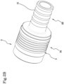
- the roto-translational element 2 is made in the form of a hollow body.
- the roto-translational element 2 has a first portion with larger diameter 2A, having the first and the second threaded portion 3, 4, and a second portion with reduced diameter 2B axially spaced from the first portion with larger diameter 2A and having a series of concentric tracks 15.
- the portion with larger diameter 2A may have the concentric tracks 15, whilst the portion with reduced diameter 2B may have the first and the second threaded portion 3, 4.
- the rotary element 5 is in effect equipped internally with a first thread 8 designed to engage rotatably with the first threaded portion 3 of the roto-translational element 2 in particular by means of a lead nut and screw or recirculating ball or roller connection in such a way as to define a first threaded connection of the helical type.
- the first thread 8 has an axial extension greater than that of the first threaded portion 3 in such a way as to define a track along which the roto-translational element 2 can move.
- the rotary element 5 is axially locked thanks to the presence, respectively, of ball bearings 6 and roller bearings 7; this means that the rotary element 5 is mounted inside the mechanical transmission "T" in such a way as to be axially locked and therefore not able to translate along a direction parallel to the axis "X" but only able to perform a rotational movement about the axis "X".
- the rotary element 5 is positioned about the roto-translational element 2 in such a way that the first thread 8 enters rotatably into contact with the first threaded portion 3 of the roto-translational element 2 positioned on the first portion with larger diameter 2A and such as to create the first threaded connection.
- the first threaded connection is of the recirculating ball type wherein the balls are recirculated inside the roto-translational element 2.
- the mechanical transmission "T” also comprises a fixed guide 9 forming part of the containment structure 1, in particular the fixed guide 9 extends from a cover "C” for closing the containment structure 1 towards the inside of the mechanical transmission "T".
- the fixed guide 9 is made using a fixed body, preferably a pin, axially inserted inside the roto-translational element 2.
- the fixed guide 9 is mounted in cantilever fashion, more preferably integral with the closing lid "C" of the containment body 1.
- the fixed guide 9 has a second thread 14 designed to engage with the second threaded portion 4 of the roto-translational element 2 in such a way as to define a second threaded connection of the helical type, preferably recirculating ball screw type wherein the balls are recirculated along the roto-translational element 2.
- the roto-translational element 2 is interposed between the rotary element 5, to which it is rotatably connected by means of the first recirculating ball threaded connection, and the fixed guide 9, to which it is connected by means of the second recirculating ball threaded connection.
- the pitches of the first and the second threaded connection have a constant value along the entire axial extension of each threaded portion 3, 4.
- first and the second threaded connection are positioned on opposite surfaces of the roto-translational element 2.
- first threaded connection is made on an outer surface of the roto-translational element 2 whilst the second threaded connection is made on the inner surface of the roto-translational element 2.
- first threaded connection is made on the outer surface of the portion with larger diameter 2A whilst the second threaded connection is made on the inner surface of the first portion with larger diameter 2A.
- first and second threaded connections are positioned in a position radially aligned one outside the other.
- first and the second threaded connection have different pitches from each other, in particular of a different module and/or of opposite direction.
- the roto-translational element 2 is therefore rotatably connected to the rotary element 5 by means of the first threaded connection defined by the first threaded portion 3 of the roto-translational element 2 and by the first thread 8 of the rotary element 5.
- the roto-translational element 2 is also engaged with the fixed guide 9 by means of the second threaded connection, defined by the second threaded portion 4 of the roto-translational element 2 and by the second thread 14 of the fixed guide 9.
- the outer surface of the portion with larger diameter 2A of the roto-translational element 2 rotates in contact with the rotary element 5 whilst the inner surface of the portion with larger diameter 2A moves in contact with the fixed guide 9.
- the roto-translational element 2 is interposed between the rotary element 5 and the fixed guide 9 and is simultaneously connected to them respectively by the first and the second threaded connection. Since the first and the second threaded connection have different pitches to each other, in particular of a different module and/ or opposite direction, they allow a variation in the angular speed between the roto-translational element 2 and the rotary element 5.
- a rotation of the rotary element 5 therefore corresponds to a roto-translation of the roto-translational element 2 the angular speed of which is different from that of the rotary element 5 and a function of the values of the pitches of the first and the second threaded connection.
- the mechanical transmission "T” also comprises a translating element 10 defining a mechanical power output unit.
- the translating element 10 is connected, by means of a circular guide 12 or one or more ball bearings, to the roto-translational element 2 for translating along the axis "X" at the same linear speed as the roto-translational element 2.
- the translating element 10 is connected to the portion with reduced diameter 2B of the roto-translational element 2 by one or more circumferential rows of balls 11, contained in the guide 12, for achieving a free rotation, and at the same time an axial connection, between the portion with reduced diameter 2B and the translating element 10.
- the circumferential rows of balls 11 may be replaced by one or more bearings, for example ball or roller bearings.
- the portion with reduced diameter 2B is rotatable relative to the translating element 10 and axially integral with the translating element 10 for translating at the same speed as the translating element 10.
- the rotary element 5 being connected to the drive unit, acts as a mechanical power input unit in the mechanical transmission "T".
Landscapes
- Engineering & Computer Science (AREA)
- General Engineering & Computer Science (AREA)
- Mechanical Engineering (AREA)
- Automation & Control Theory (AREA)
- Aviation & Aerospace Engineering (AREA)
- Transmission Devices (AREA)
Claims (15)
- Lineares mechanisches Getriebe (T), umfassend:- eine Fassungsstruktur (1);- ein Drehschiebeelement (2), das sich entlang einer Rotationsachse (X) erstreckt und einen ersten Gewindeabschnitt (3) und einen zweiten Gewindeabschnitt (4) umfasst, wobei das Drehschiebeelement (2) ausgelegt ist, um entlang der Achse (X) verschoben zu werden und sich gleichzeitig um die Achse (X) zu drehen;- ein Drehelement (5), das mit einer Antriebseinheit verbunden oder verbindbar ist, um eine mechanische Leistungseingangseinheit zu definieren, und das mit einem ersten Gewinde (8) ausgestattet ist, das ausgestaltet ist, um drehbar mit dem ersten Gewindeabschnitt (3) des Drehschiebeelements (2) in Eingriff zu gelangen, insbesondere mittels einer Schnecken-und-Spindel- oder einer Kugelumlauf- oder Wälzkupplung, sodass eine erste Gewindeverbindung (3, 8) definiert wird;- eine fixe Führung (9), die insbesondere einen Teil der Fassungsstruktur (1) bildet, aufweisend ein zweites Gewinde (14), das ausgestaltet ist, um mit dem zweiten Gewindeabschnitt (4) des Drehschiebeelements (2) in Eingriff zu gelangen, sodass eine zweite Gewindeverbindung (4, 14) definiert wird;- ein Schiebeelement (10), das entlang der Achse (X) verschoben wird und eine Leistungsausgangseinheit definiert, wobei das Schiebeelement (10) mit dem Drehschiebeelement (2) verbunden ist, um bei der gleichen Lineargeschwindigkeit wie das Drehschiebeelement (2) verschoben zu werden,wobei das Drehschiebeelement (2) gleichzeitig jeweils mit dem Drehelement (5) und der fixen Führung (9) mittels der ersten und zweiten Gewindeverbindung (3, 8; 4, 14) gekuppelt ist und wobei die erste und die zweite Gewindeverbindung (3, 8; 4, 14) unterschiedliche Steigungen aufweisen, sodass die Winkelgeschwindigkeit zwischen dem Drehschiebeelement (2) und dem Drehelement (5) variiert wird,dadurch gekennzeichnet, dass das Schiebeelement (10) mit dem Drehschiebeelement (2) durch ein oder mehrere Kugellager oder durch eine oder mehrere umfangseitige Reihen von Kugeln (11) oder durch ein oder mehrere Wälzlager verbunden ist, um eine freie Drehung und gleichzeitig eine axiale Verbindung zwischen dem Schiebeelement (10) und dem Drehschiebeelement (2) zu erzielen.
- Getriebe (T) nach Anspruch 1, wobei das Drehschiebeelement (2) in der Form eines Hohlkörpers ausgebildet ist und wobei die Gewindeverbindungen (3, 8; 4, 14) auf entgegengesetzten Oberflächen des Drehschiebeelements (2) positioniert sind, wobei insbesondere eine der Gewindeverbindungen (3, 8; 4, 14) auf einer inneren Oberfläche des Drehschiebeelements (2) ausgebildet ist und die andere der Gewindeverbindungen (3, 8; 4, 14) auf der äußeren Oberfläche des Drehschiebeelements (2) positioniert ist, sodass das Drehschiebeelement (2) zwischen dem Drehelement (5) und der fixen Führung (9) positioniert ist.
- Getriebe (T) nach Anspruch 2, wobei die erste und die zweite Gewindeverbindung (3, 8; 4, 14) in einer radial fluchtenden Position jeweils außerhalb voneinander positioniert sind.
- Getriebe (T) nach Anspruch 2 oder 3, wobei jeweils das erste und das zweite Gewinde (8, 14) des Drehelements (5) und der fixen Führung (9) eine axiale Ausdehnung aufweisen, die größer ist als die axiale Ausdehnung des ersten und zweiten Gewindeabschnitts (3, 4) des Drehschiebeelements (2), wobei die erste und die zweite Gewindeverbindung durch Umlaufkugeln ausgebildet sind, wobei die Kugeln innerhalb des Drehschiebeelements (2) in Umlauf gebracht werden.
- Getriebe (T) nach einem der Ansprüche 2 bis 4, wobei das Drehschiebeelement (2) einen ersten Abschnitt mit einem größeren Durchmesser (2A) aufweist, aufweisend die Gewindeabschnitte (3, 4), und einen zweiten Abschnitt mit einem reduzierten Durchmesser (2B), der axial vom ersten Abschnitt mit einem größeren Durchmesser (2A) beabstandet ist, wobei insbesondere der zweite Abschnitt mit einem reduzierten Durchmesser (2B) relativ zum Schiebeelement (10) drehbar und auf axial integrale Weise mit dem Schiebeelement (10) verbunden ist, um bei der gleichen Lineargeschwindigkeit wie das Schiebeelement (10) verschoben zu werden.
- Getriebe (T) nach Anspruch 5, wobei der zweite Abschnitt mit einem reduzierten Durchmesser (2B) mit dem Schiebeelement (10) durch eine oder mehrere umfangseitige Reihen von Kugeln (11) oder durch ein oder mehrere Kugellager verbunden ist, um eine freie Drehung und gleichzeitig eine axiale Verbindung zwischen dem zweiten Abschnitt mit einem reduzierten Durchmesser (2B) und dem Schiebeelement (10) zu erzielen.
- Getriebe (T) nach Anspruch 5 oder 6, wobei das Schiebeelement (10) einen kelchförmigen Abschnitt (13A) aufweist, der um den zweiten Abschnitt mit einem reduzierten Durchmesser (2B) des Drehschiebeelements (10) positioniert und drehbar mit diesem gekuppelt ist, und einen Eingriffsabschnitt (13B), der axial integral mit dem kelchförmigen Abschnitt (13A) ist und zum Kuppeln mit einer mechanischen Last (13C) ausgelegt ist, wobei der kelchförmige Abschnitt (13A) vorzugsweise eine Zugangsöffnung aufweist, die der einen oder den mehreren umfangseitigen Reihen von Kugeln (11) zugewandt und mittels einer Abdeckung wiederverschließbar ist, definierend einen Teil einer äußeren Führung für die eine oder mehreren umfangseitigen Reihen von Kugeln (11).
- Getriebe (T) nach einem der Ansprüche 3 bis 7, wobei die fixe Führung (9) unter Nutzung eines axial in das Drehschiebeelement (2) eingefügten fixen Körpers ausgebildet ist und wobei das Drehelement (5) hohl und rund um das Drehschiebeelement (2) positioniert ist.
- Getriebe (T) nach einem der Ansprüche 3 bis 7, wobei das Drehelement (5) mittels einer Drehwelle ausgebildet ist, die axial in das Drehschiebeelement (2) eingefügt ist und wobei die fixe Führung (9) rund um das Drehschiebeelement (2) positioniert ist.
- Getriebe (T) nach einem der vorhergehenden Ansprüche, wobei die erste und die zweite Gewindeverbindung (3, 8; 4, 14) in der Form von Kugelumlaufspindeln ausgebildet sind.
- Getriebe (T) nach Anspruch 10, wobei die erste Gewindeverbindung (3, 8) durch eine einzelne Kugelumlaufspindel definiert ist, die entsprechend einem spiralförmigen Weg um die Rotationsachse (X) definiert ist, und wobei die zweite Gewindeverbindung (4, 14) durch eine Vielzahl von Kugelumlaufspindeln definiert ist, die unabhängig voneinander und winkelig relativ zueinander um die Rotationsachse (X) verteilt sind.
- Getriebe (T) nach Anspruch 11, wobei die die zweite Gewindeverbindung (4, 14) definierenden Kugelumlaufspindeln von einem oder mehreren jeweiligen Führungsblöcken (17) gestützt werden, die steif mit dem Drehschiebeelement (2) verbunden sind.
- Getriebe (T) nach einem der vorhergehenden Ansprüche, wobei das Drehschiebeelement (2) durch einen hohlen monolithischen Körper definiert ist, der während der Bewegung entlang der Rotationsachse (X) in vollem Umfang innerhalb der Fassungsstruktur (1) positioniert bleibt.
- Linearantrieb (A), umfassend ein mechanisches Getriebe (T) nach einem der vorhergehenden Ansprüche und einen Elektromotor (M), der mit dem Drehelement (5) verbunden oder in einem Stück damit ausgebildet ist.
- Verwendung eines Antriebs (A) nach Anspruch 14 zum Antreiben der Steuerflächen eines Flugzeugs, insbesondere durch direkte Montage auf einer Wirkungslinie, die in Bezug auf ein Drehgelenk der Steuerflächen exzentrisch ist.
Applications Claiming Priority (2)
| Application Number | Priority Date | Filing Date | Title |
|---|---|---|---|
| IT102019000018308A IT201900018308A1 (it) | 2019-10-09 | 2019-10-09 | Trasmissione meccanica lineare a vite |
| PCT/IB2020/058828 WO2021069994A1 (en) | 2019-10-09 | 2020-09-22 | Linear mechanical screw transmission |
Publications (3)
| Publication Number | Publication Date |
|---|---|
| EP4042040A1 EP4042040A1 (de) | 2022-08-17 |
| EP4042040C0 EP4042040C0 (de) | 2025-07-02 |
| EP4042040B1 true EP4042040B1 (de) | 2025-07-02 |
Family
ID=69701309
Family Applications (1)
| Application Number | Title | Priority Date | Filing Date |
|---|---|---|---|
| EP20781101.9A Active EP4042040B1 (de) | 2019-10-09 | 2020-09-22 | Lineares mechanisches schneckengetriebe |
Country Status (5)
| Country | Link |
|---|---|
| US (1) | US11976711B2 (de) |
| EP (1) | EP4042040B1 (de) |
| ES (1) | ES3042178T3 (de) |
| IT (1) | IT201900018308A1 (de) |
| WO (1) | WO2021069994A1 (de) |
Families Citing this family (6)
| Publication number | Priority date | Publication date | Assignee | Title |
|---|---|---|---|---|
| IT201900018308A1 (it) * | 2019-10-09 | 2021-04-09 | Umbragroup S P A | Trasmissione meccanica lineare a vite |
| IT202100025793A1 (it) * | 2021-10-08 | 2023-04-08 | Paolo Barbagallo | Sistema di movimentazione |
| US12374956B2 (en) | 2022-03-11 | 2025-07-29 | Parker-Hannifin Corporation | Control surface actuator with bell crank assembly |
| IT202200020793A1 (it) * | 2022-10-10 | 2024-04-10 | Umbragroup S P A | Attuatore elettromeccanico lineare perfezionato |
| IT202300022653A1 (it) | 2023-10-27 | 2025-04-27 | Umbragroup S P A | Trasmissione meccanica lineare |
| US20260029044A1 (en) * | 2024-06-28 | 2026-01-29 | Neon Aero, Inc. | Linear actuator |
Family Cites Families (9)
| Publication number | Priority date | Publication date | Assignee | Title |
|---|---|---|---|---|
| DE102005040204A1 (de) * | 2005-08-19 | 2007-02-22 | Danaher Linear Gmbh | Kugelgewindetrieb und Verfahren zur Verschiebung einer Gewindespindel bei einem Kugelgewindetrieb |
| ITRM20120562A1 (it) * | 2012-11-15 | 2014-05-16 | Umbra Cuscinetti Spa | Attuatore elettromeccanico lineare. |
| DE112014005544A5 (de) * | 2013-12-06 | 2016-09-29 | Schaeffler Technologies AG & Co. KG | Aktuator mit einem eine Drehbewegung in eine lineare Bewegung umwandelnden Getriebe |
| DE102014108231B3 (de) * | 2014-06-12 | 2015-10-29 | Deutsches Zentrum für Luft- und Raumfahrt e.V. | Fehlertoleranter Linearaktuator |
| FR3027269B1 (fr) * | 2014-10-16 | 2016-11-25 | Bosch Gmbh Robert | Unite de commande de cable de frein de stationnement de vehicule |
| ITUB20161067A1 (it) * | 2016-02-25 | 2017-08-25 | Umbragroup S P A | Attuatore elettromeccanico lineare, preferibilmente per taglio ad acqua |
| IT201700058891A1 (it) * | 2017-05-30 | 2018-11-30 | Umbragroup S P A | Metodo per verificare un guasto elettrico, elettronico e/o meccanico in un attuatore elettromeccanico lineare |
| IT201900018305A1 (it) | 2019-10-09 | 2021-04-09 | Umbragroup S P A | Trasmissione meccanica rotativa a vite |
| IT201900018308A1 (it) * | 2019-10-09 | 2021-04-09 | Umbragroup S P A | Trasmissione meccanica lineare a vite |
-
2019
- 2019-10-09 IT IT102019000018308A patent/IT201900018308A1/it unknown
-
2020
- 2020-09-22 WO PCT/IB2020/058828 patent/WO2021069994A1/en not_active Ceased
- 2020-09-22 US US17/762,875 patent/US11976711B2/en active Active
- 2020-09-22 ES ES20781101T patent/ES3042178T3/es active Active
- 2020-09-22 EP EP20781101.9A patent/EP4042040B1/de active Active
Also Published As
| Publication number | Publication date |
|---|---|
| EP4042040C0 (de) | 2025-07-02 |
| ES3042178T3 (en) | 2025-11-18 |
| EP4042040A1 (de) | 2022-08-17 |
| US11976711B2 (en) | 2024-05-07 |
| WO2021069994A1 (en) | 2021-04-15 |
| US20220356933A1 (en) | 2022-11-10 |
| IT201900018308A1 (it) | 2021-04-09 |
Similar Documents
| Publication | Publication Date | Title |
|---|---|---|
| EP4042040B1 (de) | Lineares mechanisches schneckengetriebe | |
| EP4042039B1 (de) | Drehende mechanische schraubenübertragung | |
| US8191860B2 (en) | Low profile valve actuator having high torque output | |
| JP5308462B2 (ja) | トランスミッションのシフト要素用の作動システム | |
| KR100852870B1 (ko) | 클러치 작동 장치 | |
| US11639747B2 (en) | Linear actuator | |
| US11440181B2 (en) | Planetary gear train, gearbox and industrial robot | |
| EP4350173B1 (de) | Mechanisches drehgetriebe | |
| EP3553346B1 (de) | Schaltungsaktuator | |
| WO2021158199A2 (en) | An alternative mechanism that converts rectilinear motion into circular motion or circular motion into rectilinear motion | |
| WO2025088486A1 (en) | Linear mechanical transmission | |
| US11808332B2 (en) | Self-binding non-jamming stop module for rotary drive actuator | |
| CN221497970U (zh) | 制动驱动装置、制动器和车辆 | |
| CA3131375C (en) | Self-binding non-jamming stop module for rotary drive actuator | |
| CN120062306B (zh) | 太阳轮连接结构、具有该结构的行星减速器及电机 | |
| RU214246U1 (ru) | Электромеханический привод поступательного действия | |
| KR102020737B1 (ko) | 롤러스크류를 이용한 로터리 액츄에이터 | |
| CN111271424A (zh) | 带有卫星滚柱螺杆机构的致动机构 | |
| JP2005308181A (ja) | アクチュエータ | |
| WO2021221592A1 (en) | Alternative reduction mechanism | |
| JP2005256944A (ja) | アクチュエータ |
Legal Events
| Date | Code | Title | Description |
|---|---|---|---|
| STAA | Information on the status of an ep patent application or granted ep patent |
Free format text: STATUS: UNKNOWN |
|
| STAA | Information on the status of an ep patent application or granted ep patent |
Free format text: STATUS: THE INTERNATIONAL PUBLICATION HAS BEEN MADE |
|
| PUAI | Public reference made under article 153(3) epc to a published international application that has entered the european phase |
Free format text: ORIGINAL CODE: 0009012 |
|
| STAA | Information on the status of an ep patent application or granted ep patent |
Free format text: STATUS: REQUEST FOR EXAMINATION WAS MADE |
|
| 17P | Request for examination filed |
Effective date: 20220318 |
|
| AK | Designated contracting states |
Kind code of ref document: A1 Designated state(s): AL AT BE BG CH CY CZ DE DK EE ES FI FR GB GR HR HU IE IS IT LI LT LU LV MC MK MT NL NO PL PT RO RS SE SI SK SM TR |
|
| DAV | Request for validation of the european patent (deleted) | ||
| DAX | Request for extension of the european patent (deleted) | ||
| P01 | Opt-out of the competence of the unified patent court (upc) registered |
Effective date: 20230525 |
|
| STAA | Information on the status of an ep patent application or granted ep patent |
Free format text: STATUS: EXAMINATION IS IN PROGRESS |
|
| 17Q | First examination report despatched |
Effective date: 20231024 |
|
| GRAP | Despatch of communication of intention to grant a patent |
Free format text: ORIGINAL CODE: EPIDOSNIGR1 |
|
| STAA | Information on the status of an ep patent application or granted ep patent |
Free format text: STATUS: GRANT OF PATENT IS INTENDED |
|
| INTG | Intention to grant announced |
Effective date: 20250319 |
|
| GRAS | Grant fee paid |
Free format text: ORIGINAL CODE: EPIDOSNIGR3 |
|
| GRAA | (expected) grant |
Free format text: ORIGINAL CODE: 0009210 |
|
| STAA | Information on the status of an ep patent application or granted ep patent |
Free format text: STATUS: THE PATENT HAS BEEN GRANTED |
|
| AK | Designated contracting states |
Kind code of ref document: B1 Designated state(s): AL AT BE BG CH CY CZ DE DK EE ES FI FR GB GR HR HU IE IS IT LI LT LU LV MC MK MT NL NO PL PT RO RS SE SI SK SM TR |
|
| REG | Reference to a national code |
Ref country code: GB Ref legal event code: FG4D |
|
| REG | Reference to a national code |
Ref country code: CH Ref legal event code: EP |
|
| REG | Reference to a national code |
Ref country code: DE Ref legal event code: R096 Ref document number: 602020053861 Country of ref document: DE |
|
| REG | Reference to a national code |
Ref country code: IE Ref legal event code: FG4D |
|
| U01 | Request for unitary effect filed |
Effective date: 20250714 |
|
| U07 | Unitary effect registered |
Designated state(s): AT BE BG DE DK EE FI FR IT LT LU LV MT NL PT RO SE SI Effective date: 20250718 |
|
| PGFP | Annual fee paid to national office [announced via postgrant information from national office to epo] |
Ref country code: GB Payment date: 20250925 Year of fee payment: 6 |
|
| U20 | Renewal fee for the european patent with unitary effect paid |
Year of fee payment: 6 Effective date: 20250923 |
|
| REG | Reference to a national code |
Ref country code: ES Ref legal event code: FG2A Ref document number: 3042178 Country of ref document: ES Kind code of ref document: T3 Effective date: 20251118 |
|
| PG25 | Lapsed in a contracting state [announced via postgrant information from national office to epo] |
Ref country code: IS Free format text: LAPSE BECAUSE OF FAILURE TO SUBMIT A TRANSLATION OF THE DESCRIPTION OR TO PAY THE FEE WITHIN THE PRESCRIBED TIME-LIMIT Effective date: 20251102 |
|
| PG25 | Lapsed in a contracting state [announced via postgrant information from national office to epo] |
Ref country code: NO Free format text: LAPSE BECAUSE OF FAILURE TO SUBMIT A TRANSLATION OF THE DESCRIPTION OR TO PAY THE FEE WITHIN THE PRESCRIBED TIME-LIMIT Effective date: 20251002 |
|
| PG25 | Lapsed in a contracting state [announced via postgrant information from national office to epo] |
Ref country code: HR Free format text: LAPSE BECAUSE OF FAILURE TO SUBMIT A TRANSLATION OF THE DESCRIPTION OR TO PAY THE FEE WITHIN THE PRESCRIBED TIME-LIMIT Effective date: 20250702 |
|
| PG25 | Lapsed in a contracting state [announced via postgrant information from national office to epo] |
Ref country code: GR Free format text: LAPSE BECAUSE OF FAILURE TO SUBMIT A TRANSLATION OF THE DESCRIPTION OR TO PAY THE FEE WITHIN THE PRESCRIBED TIME-LIMIT Effective date: 20251003 |
|
| PG25 | Lapsed in a contracting state [announced via postgrant information from national office to epo] |
Ref country code: CZ Free format text: LAPSE BECAUSE OF FAILURE TO SUBMIT A TRANSLATION OF THE DESCRIPTION OR TO PAY THE FEE WITHIN THE PRESCRIBED TIME-LIMIT Effective date: 20250702 |
|
| PG25 | Lapsed in a contracting state [announced via postgrant information from national office to epo] |
Ref country code: PL Free format text: LAPSE BECAUSE OF FAILURE TO SUBMIT A TRANSLATION OF THE DESCRIPTION OR TO PAY THE FEE WITHIN THE PRESCRIBED TIME-LIMIT Effective date: 20250702 |
|
| PG25 | Lapsed in a contracting state [announced via postgrant information from national office to epo] |
Ref country code: RS Free format text: LAPSE BECAUSE OF FAILURE TO SUBMIT A TRANSLATION OF THE DESCRIPTION OR TO PAY THE FEE WITHIN THE PRESCRIBED TIME-LIMIT Effective date: 20251002 |
|
| PGFP | Annual fee paid to national office [announced via postgrant information from national office to epo] |
Ref country code: ES Payment date: 20251015 Year of fee payment: 6 |