EP4040901B1 - Verfahren und gerät zur herstellung einer mehrbenutzer-mimo-uplink-verbindung - Google Patents
Verfahren und gerät zur herstellung einer mehrbenutzer-mimo-uplink-verbindung Download PDFInfo
- Publication number
- EP4040901B1 EP4040901B1 EP22150221.4A EP22150221A EP4040901B1 EP 4040901 B1 EP4040901 B1 EP 4040901B1 EP 22150221 A EP22150221 A EP 22150221A EP 4040901 B1 EP4040901 B1 EP 4040901B1
- Authority
- EP
- European Patent Office
- Prior art keywords
- data
- sent
- network side
- sending
- terminal
- Prior art date
- Legal status (The legal status is an assumption and is not a legal conclusion. Google has not performed a legal analysis and makes no representation as to the accuracy of the status listed.)
- Active
Links
Images

Classifications
-
- H—ELECTRICITY
- H04—ELECTRIC COMMUNICATION TECHNIQUE
- H04W—WIRELESS COMMUNICATION NETWORKS
- H04W24/00—Supervisory, monitoring or testing arrangements
- H04W24/10—Scheduling measurement reports ; Arrangements for measurement reports
-
- H—ELECTRICITY
- H04—ELECTRIC COMMUNICATION TECHNIQUE
- H04B—TRANSMISSION
- H04B7/00—Radio transmission systems, i.e. using radiation field
- H04B7/02—Diversity systems; Multi-antenna system, i.e. transmission or reception using multiple antennas
- H04B7/04—Diversity systems; Multi-antenna system, i.e. transmission or reception using multiple antennas using two or more spaced independent antennas
- H04B7/0413—MIMO systems
- H04B7/0452—Multi-user MIMO systems
-
- H—ELECTRICITY
- H04—ELECTRIC COMMUNICATION TECHNIQUE
- H04J—MULTIPLEX COMMUNICATION
- H04J13/00—Code division multiplex systems
-
- H—ELECTRICITY
- H04—ELECTRIC COMMUNICATION TECHNIQUE
- H04L—TRANSMISSION OF DIGITAL INFORMATION, e.g. TELEGRAPHIC COMMUNICATION
- H04L27/00—Modulated-carrier systems
- H04L27/26—Systems using multi-frequency codes
- H04L27/2601—Multicarrier modulation systems
-
- H—ELECTRICITY
- H04—ELECTRIC COMMUNICATION TECHNIQUE
- H04W—WIRELESS COMMUNICATION NETWORKS
- H04W72/00—Local resource management
- H04W72/12—Wireless traffic scheduling
-
- H—ELECTRICITY
- H04—ELECTRIC COMMUNICATION TECHNIQUE
- H04W—WIRELESS COMMUNICATION NETWORKS
- H04W72/00—Local resource management
- H04W72/20—Control channels or signalling for resource management
-
- H—ELECTRICITY
- H04—ELECTRIC COMMUNICATION TECHNIQUE
- H04W—WIRELESS COMMUNICATION NETWORKS
- H04W74/00—Wireless channel access
- H04W74/002—Transmission of channel access control information
-
- H—ELECTRICITY
- H04—ELECTRIC COMMUNICATION TECHNIQUE
- H04W—WIRELESS COMMUNICATION NETWORKS
- H04W74/00—Wireless channel access
- H04W74/08—Non-scheduled access, e.g. ALOHA
- H04W74/0808—Non-scheduled access, e.g. ALOHA using carrier sensing, e.g. carrier sense multiple access [CSMA]
- H04W74/0816—Non-scheduled access, e.g. ALOHA using carrier sensing, e.g. carrier sense multiple access [CSMA] with collision avoidance
-
- H—ELECTRICITY
- H04—ELECTRIC COMMUNICATION TECHNIQUE
- H04W—WIRELESS COMMUNICATION NETWORKS
- H04W76/00—Connection management
- H04W76/40—Connection management for selective distribution or broadcast
Definitions
- the present application relates to the field of network technologies, and in particular, to an uplink multi-user multi-input multi-output establishment method and apparatus.
- Uplink multi-user multi-input multi-output (English: Uplink Multi-user Multi-input Multi-output, UL MU-MIMO for short) refers to a data sending manner in which multiple terminals synchronously send uplink data to a network side device.
- the network side device needs to obtain related information about to-be-sent data of the terminals, such as a data sending level and a data sending length, so as to determine scheduling information for establishing UL MU-MIMO.
- the terminals can implement UL MU-MIMO only by sending the to-be-sent data according to the scheduling information.
- the inventor finds that how to provide an effective UL MU-MIMO establishment method so that UL MU-MIMO establishment can be implemented by using less signaling interworking, so as to reduce resource overheads and improve data sending efficiency becomes a technical problem that a person skilled in the art urgently needs to resolve.
- WO 2011/112741 A1 discloses a multiple-user uplink communication system in a wireless network.
- US 2011/090855 A1 discloses an apparatus and method for managing resources in a high capacity wireless communication system using a MU-MIMO technique.
- RICHARD VAN NEE (QUALCOMM): "UL MU-MIMO for 11ac"; IEEE DRAFT; 11-09-0852-00-00AC-UL-MU-MIMO-FOR-11AC, IEEE-SA-MENTOR, PISCATAWAY, NJ USA, vol. 802.11ac, 15 July 2009 (2009-07-15), pages 1-10 , discusses issues on UL MU-MIMO for 802.11ac.
- the present application provides an uplink multi-user multi-input multi-output establishment method according to claim 1, an uplink multi-user multi-input multi-output establishment method according to claim 5, an apparatus according to claim 9, an apparatus according to claim 10, a program according to claim 11 and a computer-readable recording medium according to claim 12, which effectively implement uplink multi-user multi-input multi-output establishment, reduce resource overheads, and improve data sending efficiency.
- an uplink multi-user establishment method including:
- the receiving buffer information sent by a terminal that needs to send data includes: receiving the buffer information synchronously sent by the terminal that needs to send data.
- the receiving buffer information sent by a terminal that needs to send data includes: receiving the buffer information that is sent, in an Orthogonal Frequency Division Multiple Access resource block allocated by the network side device, by the terminal that needs to send data.
- the receiving buffer information sent by a terminal that needs to send data includes: receiving the buffer information that is sent, in an orthogonal sequence, a quasi-orthogonal sequence, or a Code Division Multiple Access sequence and in an Orthogonal Frequency Division Multiple Access resource block allocated by the network side device, by the terminal that needs to send data.
- a fourth possible implementation manner of the first aspect is further provided, where after the broadcasting, by a network side device, an uplink data sending announcement, the method further includes: receiving a request to send frame sent by the terminal that needs to send data.
- a fifth possible implementation manner of the first aspect is further provided, where the buffer information further includes a backoff timer value.
- an uplink multi-user establishment method including:
- the sending buffer information to the network side device when determining that data needs to be sent includes: when determining that data needs to be sent, sending the buffer information in an Orthogonal Frequency Division Multiple Access resource block allocated by the network side device.
- the sending buffer information to the network side device when determining that data needs to be sent includes: when determining that data needs to be sent, sending the buffer information in an orthogonal sequence, a quasi-orthogonal sequence, or a Code Division Multiple Access sequence and in an Orthogonal Frequency Division Multiple Access resource block allocated by the network side device.
- a third possible implementation manner of the second aspect is further provided, where the method further includes: sending a request to send frame to the network side device.
- an uplink multi-user establishment apparatus applied to a network side device where the apparatus includes:
- the information receiving module is specifically configured to receive the buffer information synchronously sent by the terminal that needs to send data.
- the information receiving module is specifically configured to receive the buffer information that is sent, in an Orthogonal Frequency Division Multiple access resource block allocated by the network side device, by the terminal that needs to send data.
- the information receiving module is specifically configured to receive the buffer information that is sent, in an orthogonal sequence, a quasi-orthogonal sequence, or a Code Division Multiple Access sequence and in an Orthogonal Frequency Division Multiple Access resource block allocated by the network side device, by the terminal that needs to send data.
- a fourth possible implementation manner of the third aspect is further provided, where the information receiving module is further configured to receive a request to send frame sent by the terminal that needs to send data.
- a network side device including a memory, a transmitter, a receiver, and a processor, where
- an uplink multi-user multi-input multi-output establishment apparatus applied to a terminal where the apparatus includes:
- the information sending module is specifically configured to: when determining that data needs to be sent, send the buffer information in an Orthogonal Frequency Division Multiple access resource block allocated by the network side device.
- the information sending module is specifically configured to: when determining that data needs to be sent, send the buffer information in an orthogonal sequence, a quasi-orthogonal sequence, or a Code Division Multiple Access sequence and in an Orthogonal Frequency Division Multiple Access resource block allocated by the network side device.
- the information sending module is further configured to send a request to send frame to the network side device when determining that data needs to be sent.
- a terminal including a memory, a transmitter, a receiver, and a processor, where
- a network side device broadcasts an uplink multi-user multi-input multi-output announcement, which indicates a start of uplink access.
- a terminal After receiving the uplink multi-user multi-input multi-output announcement and when determining that data needs to be sent, a terminal sends buffer information that includes at least a sending level and a data size of to-be-sent data to the network side device.
- the network side device may obtain the sending level and a data sending length of the to-be-sent data according to the buffer information, and therefore may determine scheduling information for establishing uplink multi-user multi-input multi-output.
- the network side device sends the scheduling information to a terminal that is allowed to send data.
- the terminal that is allowed to send data may send the to-be-sent data according to the scheduling information, thereby implementing uplink multi-user multi-input multi-output establishment.
- the terminal directly feeds back the buffer information that includes the sending level and the data sending length of the to-be-sent data to the network side device, and there is no need to perform multiple times of signaling interworking between the terminal and the network side device, so that signaling interworking is reduced. Therefore, resource overheads may be reduced, data sending efficiency is improved, and effective establishment of uplink multi-user multi-input multi-output is implemented.
- LTE Long Term Evolution
- WLAN Wireless Local Area Network
- a terminal may also be referred to as user equipment (User Equipment, UE), a user terminal (User Terminal, UT), a mobile terminal (Mobile Terminal, MT), a mobile station (Mobile Station, MS), and the like.
- User Equipment UE
- UT user terminal
- MT mobile terminal
- MS mobile station
- a network side device mainly refers to a wireless access point in an unlicensed frequency band, for example, an AP (Wireless Access Point, AP) in a WLAN, or may be a coordination point (Coordination Point) in a network of an unlicensed frequency band, where the coordination point undertakes coordination and control between terminals within a specific range, or may be a network side device in LTE in an unlicensed frequency spectrum (Long Term Evolution-Unlicensed, LTE-U).
- AP Wireless Access Point
- LTE-U Long Term Evolution-Unlicensed
- a network side device broadcasts an uplink multi-user multi-input multi-output announcement, which indicates a start of uplink access.
- a terminal After receiving the uplink multi-user multi-input multi-output announcement and when determining that data needs to be sent, a terminal sends buffer information that includes at least a sending level and a data size of to-be-sent data to the network side device.
- the network side device may obtain the sending level and a data sending length of the to-be-sent data according to the buffer information, and therefore may determine scheduling information for establishing uplink multi-user multi-input multi-output.
- the network side device sends the scheduling information to a terminal that is allowed to send data.
- the terminal that is allowed to send data may send the to-be-sent data according to the scheduling information, thereby implementing uplink multi-user multi-input multi-output establishment.
- the terminal directly feeds back the buffer information that includes the sending level and the data sending length of the to-be-sent data to the network side device, and there is no need to perform multiple times of signaling interworking, so that signaling interworking is reduced.
- the network side device may use a multicast manner to uniformly send scheduling information, which further reduces signaling interworking, so that resource overheads may be reduced, data sending efficiency is improved, and effective establishment of uplink multi-user multi-input multi-output is implemented.
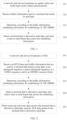
- FIG. 1 is a flowchart of an embodiment of an uplink multi-user multi-input multi-output (English: Uplink Multi-user Multi-input Multi-output, UL MU-MIMO for short) establishment method according to an embodiment of the present application, where the method may include the following several steps:
- the UMA is used to initiate uplink multi-user access, and is a start of the uplink multi-user access.
- the UMA may carry a first network allocation vector (English: Network Allocation Vector, NAV for short) value, where the first NAV value specifies a time length that needs to be occupied to send the UMA.
- NAV Network Allocation Vector
- the UMA may further carry an application identifier (English: application identifier, AID for short) of the network side device, feedback location information, and the like.
- application identifier English: application identifier, AID for short
- the terminal may determine whether data needs to be sent, and may send buffer (English: Buffer) information to the network side device if data needs to be sent.
- the buffer information includes at least a sending level and a data sending length of to-be-sent data, where the data sending length indicates a data length of the to-be-sent data, and the sending level indicates an access priority of the to-be-sent data.
- To-be-sent data of a relatively high sending level may be preferentially accessed.
- the buffer information may refer to related content that is about the to-be-sent data and buffered by the terminal in advance.
- the terminal that needs to send data may further send a request to send (English: Request To Send, RTS for short) frame that responds to the UMA to the network side device.
- a request to send English: Request To Send, RTS for short
- the terminal that needs to send data may simultaneously send an RTS frame that has same content, a same modulation manner, and a same physical waveform, thereby effectively suppressing the problem of a hidden terminal.
- the buffer information may also be simultaneously sent in a multi-antenna multi-stream manner, which is not limited in the present invention.
- a terminal that needs to send data may send an RTS frame and/or buffer information after a short interframe space (English: Short Interframe Space, SIFS for short) or a time interval.
- a short interframe space English: Short Interframe Space, SIFS for short
- SIFS Short Interframe Space
- the scheduling information may be obtained according to the sending level and the data sending length of the to-be-sent data and in the buffer information.
- the scheduling information may include an allowed sending time length, an allowed sending rate, frequency band information, and the like. That is, the scheduling information specifies which terminals perform data sending at what time in which frequency band according to which sending rate value.
- the network side device may determine, according to the buffer information fed back by the terminal that needs to send data, which terminals are allowed to send data, which may be determined according to information such as a level of the to-be-sent data, time for waiting in a queue, and a length of the to-be-sent data, and may select a terminal of a relatively high level to send data.
- the network side device may unicast, multicast, or broadcast a clear to send (English: Clear To Send, CTS for short) frame to the terminal that is allowed to send data.
- the terminal that is allowed to send data may synchronously send the to-be-sent data according to the scheduling information, so that UL MU-MIMO may be implemented.
- the network side device may further unicast, multicast, or broadcast an Acknowledgement (English: Acknowledgement, ACK for short) data packet to the terminal that is allowed to send data, so as to respond to the terminal that is allowed to send data.
- Acknowledgement English: Acknowledgement, ACK for short
- a multicast manner may be used to reduce signaling interworking for acknowledging data one by one.
- an acknowledgement manner involved in the present invention is not limited to the acknowledgement manner.
- a terminal that needs to send data may directly feed back buffer information that includes a sending level and a data sending length of to-be-sent data. Therefore, the network side device may determine, according to the buffer information, scheduling information and a terminal that is allowed to send data, and send, to the terminal that is allowed to send data, a CTS frame that carries the scheduling information.
- the terminal directly feeds back the buffer information that includes the sending level and the data sending length of the to-be-sent data, and there is no need to perform multiple times of signaling interworking, so that signaling interworking in a UL MU-MIMO establishment process is reduced. Therefore, resource overheads are reduced, and data sending efficiency may be improved.
- An encoding manner of terminal feedback information is:
- the buffer information sent by the terminal that needs to send data may be specifically encoded and sent according to a preset information format, where the preset information format includes at least a sending level field and a data length field.
- the sending level field occupies two or more bits.
- the sending level field may indicate data of four basic sending levels (that is, four levels of 00, 01, 10, and 11). Certainly, a quantity of bits occupied by the sending level field may be set according to an actual sending level requirement.
- the data length field is used to indicate a size of to-be-sent data. Because a data sending length may vary, a quantity of bits of the data length field should cover a maximum data length. To save resources and avoid resource waste caused by a relatively large data length field but a relatively small actually sent data, the terminal may perform data encoding on the to-be-sent data when sending the to-be-sent data, where the data length field only stores an encoded value, so that the quantity of bits occupied by the data length field may be reduced, and resources are saved.
- the data encoding manner may be notified to the terminal by the network side device, and the terminal is requested to perform encoding according to the data encoding manner; or the terminal performs encoding according to a data encoding manner and feeds back the data encoding manner to the network side device.
- the buffer information may further indicate data indication information and a backoff timer (English: Backoff timer) value, where the data indication information is used to indicate whether the terminal needs to send data, and the backoff timer value specifies, when a data conflict occurs, time for waiting to send data.
- the network side device may specifically determine, from the terminal that needs to send data and according to the backoff timer value and the sending level of the to-be-sent data, the terminal that is allowed to send data.
- the preset information format may further include a data indication field and a backoff timer value field.
- Table 1 below shows a possible implementation manner of the preset information format.
- Data indication field Sending level field
- the preset information format may be sent to the terminal by the network side device, and may be carried when the UMA is broadcast, or may be separately sent to the terminal.
- different terminals that need to send data may synchronously send the buffer information and/or the RTS frame, so that the network side device may synchronously receive the buffer information and/or the RTS frame sent by different terminals that need to send data.
- the UMA sent by the network side device may carry a sending parameter, and the terminal that needs to send data may send the buffer information and/or the RTS frame according to the sending parameter, so as to ensure synchronous sending with another terminal that needs to send data.
- the sending parameter specifies a sending time or the like for feeding back the buffer information and/or the RTS frame.
- the terminal may use a manner of Orthogonal Frequency Division Multiple Access (English: Orthogonal Frequency Division Multiple Access, OFDMA for short) to send the buffer information and/or the RTS frame. That is, the terminal sends the buffer information and/or the RTS frame in a corresponding OFDMA resource block.
- the network side device may synchronously receive, in different OFDMA resource blocks, information sent by different terminals.
- the terminal may send the buffer information and/or the RTS frame in an orthogonal sequence, a quasi-orthogonal sequence, or a Code Division Multiple Access (English: Code Division Multiple Access, CDMA for short) sequence in the corresponding OFDMA resource block. Therefore, the network side device may receive, in one OFDMA resource block, the buffer information and/or the RTS frame sent by different terminals, so that resource overheads may be reduced.
- the OFDMA resource block and/or the orthogonal sequence, the quasi-orthogonal sequence, or the CDMA sequence that are/is used by the terminal may be allocated by the network side device.
- Resource allocation information of the network side device may be carried in the UMA to be notified to each terminal, or the resource allocation information may be separately sent to the terminal that has a data feedback request.
- the network side device may further adjust a size of the OFDMA resource block according to precision of the buffer information, so as to ensure normal data sending and avoid resource waste.
- the precision of the buffer information may specifically refer to a size of the buffer information.
- FIG. 2 which is a flowchart of another embodiment of a UL MU-MIMO establishment method according to an embodiment of the present application, the method may include the following several steps: 201.
- a network side device broadcasts a UMA.
- the buffer information includes at least a sending level and a data sending length of to-be-sent data, and may further include information such as data indication information and a backoff timer value.
- the OFDMA resource block allocated by the network side device, and resource allocation information of any one of the orthogonal sequence, the quasi-orthogonal sequence, or the CDMA sequence may be carried in the UMA to be sent.
- a manner of the orthogonal sequence, the quasi-orthogonal sequence, or the CDMA sequence is used to simultaneously feed back, in a same time frequency resource, the buffer information to the network side device.
- the present invention works in an unlicensed frequency spectrum, and there is a problem of a hidden terminal. Therefore, the terminal that needs to send data may send an RTS frame before feeding back the buffer information, so as to protect subsequent data from being interfered by the hidden terminal.
- a feasible manner in which the terminal that needs to send data feeds back the RTS frame is that the terminal that needs to send data simultaneously sends a same RTS frame, so as to protect UL MU-MIMO sending.
- a traditional RTS frame carries a source address and a destination address.
- the source address may use a same default address, or may be specified by the network side device.
- a manner of determining the source address is not limited in the present invention.
- the destination address is a network side device address.
- Information such as NAV length information in the RTS frame may be agreed in advance with the network side device.
- the terminal may obtain the information by using the UMA, or may obtain the information from other broadcast or multicast information of a network layer.
- the network side device may use a manner of unicast, multicast, or broadcast to send, to the terminal that is allowed to send data, the clear to send frame that carries the scheduling information.
- a multicast manner may be used to further reduce signaling interworking and resource overheads.
- the network side device may use the manner of unicast, multicast, or broadcast to send the ACK data packet.
- the ACK data packet is used to notify the terminal that is allowed to send data that the network side device has succeeded in receiving the data sent by the terminal that is allowed to send data.
- a terminal that needs to send data may feed back, in an OFDMA resource block allocated by the network side device, buffer information that includes a sending level and a data sending length of to-be-sent data. Therefore, the network side device may determine, according to the buffer information, scheduling information and a terminal that is allowed to send data, and send, to the terminal that is allowed to send data, a CTS frame that carries the scheduling information.
- the terminal directly feeds back the buffer information that includes the sending level and the data sending length of the to-be-sent data, and there is no need to perform multiple times of signaling interworking. Therefore, signaling interworking in a UL MU-MIMO establishment process is reduced, resource overheads are reduced, and data sending efficiency may be improved.
- the UMA may further carry requirement information, and the terminal may only feed back, according to the requirement information, buffer content that is corresponding to the requirement information and in the buffer information.
- the network side device receives the buffer content that is corresponding to the requirement information and in the buffer information, and may further request, according to an actual situation, the terminal to send other buffer content in the buffer information.
- sending of buffer content included in the buffer information may be completed once, or may be completed by multiple times of sending. Therefore, corresponding buffer content requested by the network side device may be fed back each time according to an information requirement scheduled by the network side device, so that system overheads may be reduced, and scheduling may be flexibly performed.
- the RTS frame may carry a second NAV value, where the second NAV value specifies a time length that needs to be occupied to send the RTS frame and the buffer information.
- the second NAV value specifies a time length that needs to be occupied to send the RTS frame and the buffer information.
- the second NAV value specifies a time length that needs to be occupied to send the RTS frame, the buffer information, UL MU-MIMO data, and the ACK data packet.
- all devices unrelated to the UL MU-MIMO sending perform no other service processing in the time length specified by the second NAV value, so that a processing process of the RTS frame, the buffer information, the UL MU data, and the ACK data packet may be protected.
- a CTS frame sent by the network side device may carry a third NAV value, where the third NAV value specifies a time length that needs to be occupied to send the CTS frame.
- the terminal After receiving the CTS frame, the terminal performs, according to the third NAV value, no other service processing in the time length specified by the third NAV value, so as to protect a processing process of the CTS frame.
- FIG. 3 is a flowchart of still another embodiment of a UL MU-MIMO establishment method according to an embodiment of the present application, where the method may include the following several steps:
- the terminal may further send an RTS frame to the network side device.
- a problem of a hidden terminal may be resolved by sending the RTS frame, so that information loss is avoided.
- the RTS frame and the buffer information may be simultaneously sent, or may be sent at different time.
- the terminal may specifically send the buffer information and/or the RTS frame to the network side device according to a sending parameter sent by the network side device, so as to ensure that the terminal and another terminal may simultaneously send their respective buffer information and/or RTS frames. Therefore, the network side device may simultaneously receive RTS frames and/or buffer information sent by different terminals that need to send data.
- the sending parameter specifies a sending time or the like for feeding back the buffer information and/or the RTS frame.
- the terminal when determining that data needs to be sent, may specifically send the buffer information in an Orthogonal Frequency Division Multiple Access OFDMA resource block allocated by the network side device.
- the terminal when determining that data needs to be sent, may specifically send the buffer information in an orthogonal sequence, a quasi-orthogonal sequence, or a Code Division Multiple Access CDMA sequence and in an Orthogonal Frequency Division Multiple Access OFDMA resource block allocated by the network side device.
- the network side device may determine, according to buffer content in the buffer information, the scheduling information for establishing UL MU-MIMO, and then may send, to a terminal that is allowed to send data, the CTS frame that carries the scheduling information.
- the terminal If the terminal receives a CTS frame multicast by the network side device, the terminal sends the to-be-sent data according to the scheduling information, so that UL MU-MIMO establishment may be implemented.
- a terminal receives a UMA broadcast by a network side device, and when determining that data needs to be sent, feeds back buffer information that includes a sending level and a data sending length of to-be-sent data to the network side device.
- the network side device may determine scheduling information according to the buffer information, select a terminal that is allowed to send data, and multicast a CTS frame that carries the scheduling information. There is no need to respond to each terminal one by one, and a uniform response may be made, so that signaling interworking is reduced.
- the terminal After receiving the CTS frame, the terminal may send the to-be-sent data according to the scheduling information, so as to implement UL MU-MIMO establishment.
- the terminal directly feeds back the buffer information that includes the sending level and the data sending length of the to-be-sent data, and there is no need to perform multiple times of signaling interworking, so that signaling interworking in a UL MU-MIMO establishment process is further reduced, resource overheads are reduced, and data sending efficiency may be improved.
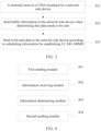
- FIG. 4 is a schematic structural diagram of an embodiment of a UL MU-MIMO establishment apparatus according to an embodiment of the present application, where the apparatus is specifically applied to a network side device.
- the apparatus may include a first sending module 401, an information receiving module 402, an information determining module 403, and a second sending module 404.
- the first sending module 401 is configured to broadcast a UMA.
- the information receiving module 402 is configured to receive buffer information sent by a terminal that needs to send data.
- the UMA is used to initiate uplink multi-user access, and is a start of the uplink multi-user access.
- the UMA may carry a first network allocation vector (English: Network Allocation Vector, NAV for short) value, where the first NAV value specifies a time length that needs to be occupied to send the UMA.
- NAV Network Allocation Vector
- the UMA may further carry an application identifier (English: application identifier, AID for short) of the network side device, feedback location information, and the like.
- application identifier English: application identifier, AID for short
- the terminal may determine whether data needs to be sent, and may send buffer information to the network side device if data needs to be sent.
- the buffer information includes at least a sending level and a data sending length of to-be-sent data.
- the information determining module 403 is configured to determine, according to the buffer information, scheduling information for establishing UL MU-MIMO.
- the second sending module 404 is configured to select, from the terminal that needs to send data, a terminal that is allowed to send data, and send, to the terminal that is allowed to send data, a clear to send frame that carries the scheduling information, so that the terminal that is allowed to send data sends the to-be-sent data according to the scheduling information.
- the second sending module 404 may unicast, multicast, or broadcast a clear to send (English: Clear To Send, CTS for short) frame to the terminal that is allowed to send data.
- a clear to send English: Clear To Send, CTS for short
- the terminal that is allowed to send data may synchronously send the to-be-sent data according to the scheduling information, so that UL MU-MIMO may be implemented.
- the network side device may further unicast, multicast, or broadcast an Acknowledgement (English: Acknowledgement, ACK for short) data packet to the terminal that is allowed to send data, so as to respond to the terminal that is allowed to send data.
- Acknowledgement English: Acknowledgement, ACK for short
- a multicast manner may be used to reduce signaling interworking for acknowledging data one by one.
- an acknowledgement manner involved in the present invention is not limited to the acknowledgement manner.
- a terminal that needs to send data may directly feed back buffer information that includes a sending level and a data sending length of to-be-sent data. Therefore, scheduling information and a terminal that is allowed to send data may be determined according to the buffer information, and a CTS frame that carries the scheduling information may be sent to the terminal that is allowed to send data.
- the terminal directly feeds back the buffer information that includes the sending level and the data sending length of the to-be-sent data, and there is no need to perform multiple times of signaling interworking, so that signaling interworking in a UL MU-MIMO establishment process is reduced. Therefore, resource overheads are reduced, and data sending efficiency may be improved.
- the terminal that needs to send data may further send an RTS frame that responds to the UMA to the network side device.
- the terminal that needs to send data may simultaneously send an RTS frame that has same content, a same modulation manner, and a same physical waveform, thereby effectively suppressing the problem of a hidden terminal.
- the terminal that needs to send data may specifically send the RTS frame before feeding back the buffer information.
- the information receiving module 402 may further be configured to receive the RTS frame sent by the terminal that needs to send data.
- the buffer information may also be simultaneously sent in a multi-antenna multi-stream manner, which is not limited in the present invention.
- a terminal that needs to send data may send an RTS frame and/or buffer information after a short interframe space (English: Short Interframe Space, SIFS for short) or a time interval.
- a short interframe space English: Short Interframe Space, SIFS for short
- SIFS Short Interframe Space
- a feasible manner in which the terminal that needs to send data feeds back the RTS frame is that the terminal that needs to send data simultaneously sends a same RTS frame, so as to protect UL MU-MIMO sending.
- a traditional RTS frame carries a source address and a destination address.
- the source address may use a same default address, or may be specified by the network side device.
- a manner of determining the source address is not limited in the present invention.
- the destination address is a network side device address.
- Information such as NAV length information in the RTS frame may be agreed in advance with the network side device.
- the terminal may obtain the information by using the UMA, or may obtain the information from other broadcast or multicast information of a network layer.
- different terminals that need to send data may synchronously send the buffer information and/or the RTS frame, so that the information receiving module may synchronously receive the buffer information and/or the RTS frame sent by different terminals that need to send data.
- the information receiving module 402 is specifically configured to receive the buffer information synchronously sent by the terminal that needs to send data.
- the terminal may use a manner of Orthogonal Frequency Division Multiple Access (English: Orthogonal Frequency Division Multiple Access, OFDMA for short) to send the buffer information and/or the RTS frame. That is, the terminal sends the buffer information and/or the RTS frame in a corresponding OFDMA resource block.
- Orthogonal Frequency Division Multiple Access English: Orthogonal Frequency Division Multiple Access, OFDMA for short
- the information receiving module 402 is specifically configured to receive the buffer information sent by the terminal that needs to send data and in an allocated OFDMA resource block.
- the information receiving module may synchronously receive, in different OFDMA resource blocks, information sent by different terminals.
- the terminal may send the buffer information and/or the RTS frame in an orthogonal sequence, a quasi-orthogonal sequence, or a Code Division Multiple Access (English: Code Division Multiple Access, CDMA for short) sequence in the corresponding OFDMA resource block.
- an orthogonal sequence a quasi-orthogonal sequence
- a Code Division Multiple Access English: Code Division Multiple Access, CDMA for short
- the information receiving module 402 is specifically configured to receive the buffer information sent by the terminal that needs to send data, in an orthogonal sequence, a quasi-orthogonal sequence, or a CDMA sequence, and in an allocated OFDMA resource block.
- the information receiving module may receive, in one OFDMA resource block, the buffer information and/or the RTS frame sent by different terminals, so that resource overheads may be reduced.
- the OFDMA resource block and/or the orthogonal sequence, the quasi-orthogonal sequence, or the CDMA sequence that are/is used by the terminal may be allocated by the network side device.
- Resource allocation information of the network side device may be carried in the UMA to be notified to each terminal, or the resource allocation information may be separately sent to the terminal that has a data feedback request.
- the network side device may further adjust a size of the OFDMA resource block according to precision of the buffer information, so as to ensure normal data sending and avoid resource waste.
- the precision of the buffer information may specifically refer to a size of the buffer information.
- the RTS frame may carry a second NAV value, where the second NAV value specifies a time length that needs to be occupied to send the RTS frame and the buffer information.
- the second NAV value specifies a time length that needs to be occupied to send the RTS frame and the buffer information.
- the second NAV value specifies a time length that needs to be occupied to send the RTS frame, the buffer information, UL MU-MIMO data, and the ACK data packet.
- all devices unrelated to the UL MU-MIMO sending perform no other service processing in the time length specified by the second NAV value, so that a processing process of the RTS frame, the buffer information, the UL MU data, and the ACK data packet may be protected.
- a multicast CTS frame sent by the second sending module may carry a third NAV value, where the third NAV value specifies a time length that needs to be occupied to send the CTS frame.
- the terminal After receiving the CTS frame, the terminal performs, according to the third NAV value, no other service processing in the time length specified by the third NAV value, so as to protect a processing process of the CTS frame.
- the UL MU-MIMO establishment apparatus described in the foregoing embodiment may be integrated into a network side device in practical application.
- a network device on which the UL MU-MIMO establishment apparatus in the embodiment of the present application is deployed may quickly and efficiently implement control of an application program and reduce tedious operation steps, thereby reducing signaling interworking in a UL MU-MIMO establishment process. Therefore, resource overheads are reduced, and data sending efficiency may be improved.
- an embodiment of the present application further provides a network side device, where the network side device includes at least a transmitter 501, a receiver 502, a memory 503, and a processor 504.
- the memory 503 stores a set of program instructions.
- the memory may be a high-speed RAM memory, or may be a non-volatile memory (non-volatile memory), such as at least one magnetic disk memory.
- the processor 504 is configured to invoke the program instructions stored in the memory 503, so as to execute the following operations:
- the processor may be a central processing unit CPU, or an application specific integrated circuit ASIC (Application Specific Integrated Circuit), or one or more integrated circuits configured to implement this embodiment of the present invention.
- CPU central processing unit
- ASIC Application Specific Integrated Circuit
- FIG. 6 is a schematic structural diagram of another embodiment of a UL MU-MIMO establishment apparatus according to an embodiment of the present application, where the apparatus is specifically applied to a terminal.
- the apparatus may include:
- the information sending module may further send an RTS frame to the network side device.
- a problem of a hidden terminal may be resolved by sending the RTS frame, so that information loss is avoided.
- the RTS frame and the buffer information may be simultaneously sent, or may be sent at different time.
- the information sending module may specifically send the buffer information to the network side device according to a sending parameter sent by the network side device, so that the network side device may simultaneously receive RTS frames and/or buffer information sent by different terminals that need to send data.
- the sending parameter specifies a sending time or the like for feeding back the buffer information.
- the information sending module may specifically send the buffer information in an Orthogonal Frequency Division Multiple Access OFDMA resource block allocated by the network side device.
- the information sending module may specifically send the buffer information in an orthogonal sequence, a quasi-orthogonal sequence, or a Code Division Multiple Access CDMA sequence and in an Orthogonal Frequency Division Multiple Access OFDMA resource block allocated by the network side device.
- the network side device may determine, according to buffer content in the buffer information, the scheduling information for establishing UL MU-MIMO, and then may send, to a terminal that is allowed to send data, the CTS frame that carries the scheduling information.
- the data sending module may send the to-be-sent data according to the scheduling information, so as to implement UL MU-MIMO establishment.
- the buffer information sent by the information sending module may be specifically encoded and sent according to a preset information format.
- a preset information format For tire preset information format, reference may be made to the description in the method embodiment, and details are not described herein.
- a UMA broadcast by a network side device is received, and when it is determined that data needs to be sent, buffer information that includes a sending level and a data sending length of to-be-sent data is fed back to the network side device.
- the network side device may determine scheduling information according to the buffer information, select a terminal that is allowed to send data, and multicast a CTS frame that carries the scheduling information. There is no need to respond to each terminal one by one, and a uniform response may be made, so that signaling interworking is reduced.
- the terminal After receiving the CTS frame, the terminal may send the to-be-sent data according to the scheduling information, so as to implement UL MU-MIMO establishment.
- the terminal directly feeds back the buffer information that includes the sending level and the data sending length of the to-be-sent data, and there is no need to perform multiple times of signaling interworking, so that signaling interworking in a UL MU-MIMO establishment process is further reduced, resource overheads are reduced, and data sending efficiency may be improved.
- the UL MU-MIMO establishment apparatus described in the foregoing embodiment shown in FIG. 6 may be integrated into a terminal in practical application.
- a terminal on which the UL MU-MIMO establishment apparatus in the embodiment of the present application is deployed may quickly and efficiently implement control of an application program and reduce tedious operation steps, thereby reducing signaling interworking in a UL MU-MIMO establishment process. Therefore, resource overheads are reduced, and data sending efficiency may be improved.
- an embodiment of the present application further provides a terminal, where the terminal includes at least a transmitter 701, a receiver 702, a memory 703, and a processor 704.
- the memory 503 stores a set of program instructions.
- the memory may be a high-speed RAM memory, or may be a non-volatile memory (non-volatile memory), such as at least one magnetic disk memory.
- the processor 504 is configured to invoke the program instructions stored in the memory 503, so as to execute the following operations:
- the processor may be a central processing unit CPU, or an application specific integrated circuit ASIC (Application Specific Integrated Circuit), or one or more integrated circuits configured to implement this embodiment of the present invention.
- CPU central processing unit
- ASIC Application Specific Integrated Circuit
Landscapes
- Engineering & Computer Science (AREA)
- Computer Networks & Wireless Communication (AREA)
- Signal Processing (AREA)
- Mobile Radio Communication Systems (AREA)
Claims (12)
- Aufwärtsstrecken-Mehrbenutzer-Mehrfach-Eingang-Mehrfach-Ausgang-Herstellungsverfahren, umfassend:Rundsenden (101, 201) einer Aufwärtsstrecken-Datensendeansage durch eine netzseitige Vorrichtung;gleichzeitiges Empfangen (102, 202) von Pufferinformationen, die durch verschiedene Endgeräte gesendet werden, die Daten senden müssen, wobei die Pufferinformationen mindestens einen Sendepegel und eine Datensendelänge von zu sendenden Daten umfassen, wobei der Sendepegel eine Zugriffspriorität der zu sendenden Daten angibt;Bestimmen (103, 203), gemäß den Pufferinformationen, von Ablaufplanungsinformationen zum Herstellen von Mehrbenutzer-Mehrfach-Eingang-Mehrfach-Ausgang;Senden (104, 204) eines Rahmens, der die Ablaufplanungsinformationen führt, zu einem Endgerät, dem erlaubt ist, Daten zu senden, wobei das Endgerät, dem erlaubt ist, Daten zu senden, aus Endgeräten ausgewählt wird, die Daten senden müssen, undEmpfangen der zu sendenden Daten von dem Endgerät, dem erlaubt ist, Daten zu senden, gemäß den Ablaufplanungsinformationen,wobei das gleichzeitige Empfangen von Pufferinformationen, die durch verschiedene Endgeräte gesendet werden, die Daten senden müssen, Folgendes umfasst:
Empfangen (202) der Pufferinformationen, die gesendet werden, in verschiedenen durch die netzseitige Vorrichtung zugeteilten Orthogonalfrequenzmultiplex-Mehrfachzugriffs-Ressourcenblöcken, durch die Endgeräte, die Daten senden müssen. - Verfahren nach Anspruch 1, das ferner nach dem Empfangen der zu sendenden Daten Folgendes umfasst: Senden (205) eines ACK-Datenpakets zu dem Endgerät, dem erlaubt ist, Daten zu senden.
- Verfahren nach Anspruch 1 oder Anspruch 2, wobei das Verfahren nach dem Rundsenden einer Aufwärtsstrecken-Datensendeansage durch eine netzseitige Vorrichtung ferner Folgendes umfasst:
Empfangen einer Anforderung des Sendens eines durch das Endgerät, das Daten senden muss, gesendeten Rahmens. - Verfahren nach einem der Ansprüche 1 bis 3, wobei die Pufferinformationen ferner einen Zurückhalte-Timerwert umfassen.
- Aufwärtsstrecken-Mehrbenutzer-Mehrfach-Eingang-Mehrfach-Ausgang-Herstellungsverfahren, umfassend:Empfangen (301) einer durch eine netzseitige Vorrichtung gesendeten Aufwärtsstrecken-Datensendeansage durch verschiedene Endgeräte,Senden (302) von Pufferinformationen zu der netzseitigen Vorrichtung, wenn bestimmt wird, dass Daten gesendet werden müssen, wobei die Pufferinformationen mindestens einen Sendepegel und eine Datensendelänge von zu sendenden Daten umfassen, wobei der Sendepegel eine Zugriffspriorität der zu sendenden Daten angibt; undwenn ein Rahmen empfangen wird, der Ablaufplanungsinformationen führt und durch die netzseitige Vorrichtung gesendet wird, Senden (303) der zu sendenden Daten zu der netzseitigen Vorrichtung gemäß den Ablaufplanungsinformationen, wobei die Ablaufplanungsinformationen durch die netzseitige Vorrichtung gemäß den Pufferinformationen bestimmt werden,wobei das Senden (302) von Pufferinformationen zu der netzseitigen Vorrichtung,wenn bestimmt wird, dass Daten gesendet werden müssen, Folgendes umfasst:
wenn bestimmt wird, dass Daten gesendet werden müssen, Senden der Pufferinformationen in einem durch die netzseitige Vorrichtung zugeteilten Orthogonalfrequenzmultiplex-Mehrfachzugriffs-Ressourcenblock, wodurch es der netzseitigen Vorrichtung ermöglicht wird, gleichzeitig in verschiedenen OFDMA-Ressourcenblöcken Informationen zu empfangen, die durch verschiedene Endgeräte gesendet werden. - Verfahren nach Anspruch 5, das ferner nach dem Senden der zu sendenden Daten zu der netzseitigen Vorrichtung Folgendes umfasst: Empfangen eines ACK-Datenpakets von der netzseitigen Vorrichtung.
- Verfahren nach Anspruch 5 oder Anspruch 6, wobei, wenn bestimmt wird, dass Daten gesendet werden müssen, das Verfahren ferner Folgendes umfasst:
Senden einer Anforderung des Rahmen-Sendens zu der netzseitigen Vorrichtung. - Verfahren nach einem der Ansprüche 5 bis 7, wobei die Pufferinformationen ferner einen Zurückhalte-Timerwert umfassen.
- Netzseitiges Gerät, das dafür ausgelegt ist, das Verfahren nach einem der Ansprüche 1 bis 4 auszuführen.
- Endgerät, das dafür ausgelegt ist, das Verfahren nach einem der Ansprüche 5 bis 8 auszuführen.
- Programm, das, wenn es durch einen in einem netzseitigen Gerät enthaltenen Computer ausgeführt wird, bewirkt, dass das netzseitige Gerät das Verfahren nach einem der Ansprüche 1 des 4 ausführt, und, wenn es durch einen in einem Endgerät enthaltenen Computer ausgeführt wird, bewirkt, dass das Endgerät das Verfahren nach einem der Ansprüche 5 bis 8 ausführt.
- Computerlesbares Aufzeichnungsmedium, auf dem ein Programm aufgezeichnet ist, wobei das Programm, wenn es durch einen in einem netzseitigen Gerät enthaltenen Computer ausgeführt wird, bewirkt, dass das netzseitige Gerät das Verfahren nach einem der Ansprüche 1 des 4 ausführt, und, wenn es durch einen in einem Endgerät enthaltenen Computer ausgeführt wird, bewirkt, dass das Endgerät das Verfahren nach einem der Ansprüche 5 bis 8 ausführt.
Priority Applications (1)
| Application Number | Priority Date | Filing Date | Title |
|---|---|---|---|
| EP22150221.4A EP4040901B1 (de) | 2014-05-30 | 2014-05-30 | Verfahren und gerät zur herstellung einer mehrbenutzer-mimo-uplink-verbindung |
Applications Claiming Priority (3)
| Application Number | Priority Date | Filing Date | Title |
|---|---|---|---|
| EP22150221.4A EP4040901B1 (de) | 2014-05-30 | 2014-05-30 | Verfahren und gerät zur herstellung einer mehrbenutzer-mimo-uplink-verbindung |
| PCT/CN2014/078918 WO2015180131A1 (zh) | 2014-05-30 | 2014-05-30 | 上行链路多用户多输入多输出建立方法和装置 |
| EP14893637.0A EP3133859B1 (de) | 2014-05-30 | 2014-05-30 | Verfahren und vorrichtung zum aufbau von uplink-multi-input-multi-output für mehrere benutzer |
Related Parent Applications (2)
| Application Number | Title | Priority Date | Filing Date |
|---|---|---|---|
| EP14893637.0A Division EP3133859B1 (de) | 2014-05-30 | 2014-05-30 | Verfahren und vorrichtung zum aufbau von uplink-multi-input-multi-output für mehrere benutzer |
| EP14893637.0A Division-Into EP3133859B1 (de) | 2014-05-30 | 2014-05-30 | Verfahren und vorrichtung zum aufbau von uplink-multi-input-multi-output für mehrere benutzer |
Publications (3)
| Publication Number | Publication Date |
|---|---|
| EP4040901A1 EP4040901A1 (de) | 2022-08-10 |
| EP4040901C0 EP4040901C0 (de) | 2025-02-19 |
| EP4040901B1 true EP4040901B1 (de) | 2025-02-19 |
Family
ID=54697908
Family Applications (2)
| Application Number | Title | Priority Date | Filing Date |
|---|---|---|---|
| EP22150221.4A Active EP4040901B1 (de) | 2014-05-30 | 2014-05-30 | Verfahren und gerät zur herstellung einer mehrbenutzer-mimo-uplink-verbindung |
| EP14893637.0A Active EP3133859B1 (de) | 2014-05-30 | 2014-05-30 | Verfahren und vorrichtung zum aufbau von uplink-multi-input-multi-output für mehrere benutzer |
Family Applications After (1)
| Application Number | Title | Priority Date | Filing Date |
|---|---|---|---|
| EP14893637.0A Active EP3133859B1 (de) | 2014-05-30 | 2014-05-30 | Verfahren und vorrichtung zum aufbau von uplink-multi-input-multi-output für mehrere benutzer |
Country Status (4)
| Country | Link |
|---|---|
| US (3) | US10405221B2 (de) |
| EP (2) | EP4040901B1 (de) |
| CN (1) | CN106465168B (de) |
| WO (1) | WO2015180131A1 (de) |
Families Citing this family (5)
| Publication number | Priority date | Publication date | Assignee | Title |
|---|---|---|---|---|
| US10470176B2 (en) * | 2014-06-18 | 2019-11-05 | Qualcomm Incorporated | Protection for multi-user transmissions |
| US10517021B2 (en) | 2016-06-30 | 2019-12-24 | Evolve Cellular Inc. | Long term evolution-primary WiFi (LTE-PW) |
| US10715581B2 (en) * | 2017-01-25 | 2020-07-14 | International Business Machines Corporation | System and method to download file from common recipient devices in proximity |
| CN107277932B (zh) * | 2017-06-20 | 2020-08-11 | 南京邮电大学 | 一种多用户mimo系统用户调度方法 |
| CN114245419B (zh) * | 2021-10-26 | 2025-07-04 | 新华三大数据技术有限公司 | 一种实现ofdma的方法、ap和存储介质 |
Citations (1)
| Publication number | Priority date | Publication date | Assignee | Title |
|---|---|---|---|---|
| WO2011112741A1 (en) * | 2010-03-09 | 2011-09-15 | Qualcomm Incorporated | Multi-user uplink communication using edca with polling |
Family Cites Families (8)
| Publication number | Priority date | Publication date | Assignee | Title |
|---|---|---|---|---|
| AU2010282562B2 (en) * | 2009-08-12 | 2015-04-02 | Interdigital Patent Holdings, Inc. | Method and apparatus for contention-based uplink data transmission |
| KR101711657B1 (ko) * | 2009-10-20 | 2017-03-02 | 한국전자통신연구원 | 고용량 무선 통신 시스템에서의 자원 관리 방법 |
| US8306010B2 (en) * | 2010-04-28 | 2012-11-06 | Intel Corporation | Systems and methods for uplink multi-user multiple input multiple output (MU MIMO) medium access and error recovery |
| TW201210238A (en) * | 2010-05-06 | 2012-03-01 | Htc Corp | Method of handling a physical uplink control channel transmission and related communication device |
| US9306785B2 (en) * | 2011-10-17 | 2016-04-05 | Lg Electronics Inc. | Method and apapratus for transmitting a frame in a wireless LAN system |
| TW201407973A (zh) * | 2012-05-09 | 2014-02-16 | Interdigital Patent Holdings | 在無線區域網路及無線傳送接收單元中多使用者多輸入多輸出通訊 |
| US9800501B2 (en) * | 2013-08-28 | 2017-10-24 | Qualcomm Incorporated | Methods and apparatus for multiple user uplink |
| US20170332385A1 (en) * | 2016-05-11 | 2017-11-16 | Qualcomm Incorporated | Buffer status reporting in a wireless local area network (wlan) |
-
2014
- 2014-05-30 EP EP22150221.4A patent/EP4040901B1/de active Active
- 2014-05-30 CN CN201480078621.XA patent/CN106465168B/zh active Active
- 2014-05-30 WO PCT/CN2014/078918 patent/WO2015180131A1/zh not_active Ceased
- 2014-05-30 EP EP14893637.0A patent/EP3133859B1/de active Active
-
2016
- 2016-11-21 US US15/357,816 patent/US10405221B2/en active Active
-
2019
- 2019-07-30 US US16/526,067 patent/US11284283B2/en active Active
-
2022
- 2022-02-18 US US17/675,597 patent/US11956661B2/en active Active
Patent Citations (1)
| Publication number | Priority date | Publication date | Assignee | Title |
|---|---|---|---|---|
| WO2011112741A1 (en) * | 2010-03-09 | 2011-09-15 | Qualcomm Incorporated | Multi-user uplink communication using edca with polling |
Non-Patent Citations (6)
| Title |
|---|
| "3rd Generation Partnership Project; Technical Specification Group Radio Access Network; Further Advancements for E-UTRA Physical Layer Aspects (Release 9)", 3GPP STANDARD; 3GPP TR 36.814, 3RD GENERATION PARTNERSHIP PROJECT (3GPP), MOBILE COMPETENCE CENTRE ; 650, ROUTE DES LUCIOLES ; F-06921 SOPHIA-ANTIPOLIS CEDEX ; FRANCE, vol. RAN WG1, no. V1.7.0, 13 May 2014 (2014-05-13), pages 1 - 85, XP050773866, [retrieved on 20140513] * |
| ANDREAS MAEDER ET AL: "OFDMA in the field", COMPUTER COMMUNICATION REVIEW, ACM, NEW YORK, NY, US, vol. 40, no. 5, 22 October 2010 (2010-10-22), pages 71 - 76, XP058185966, ISSN: 0146-4833, DOI: 10.1145/1880153.1880165 * |
| CHOI JINSOO ET AL: "Discussion on OFDMA in HEW Date: 2013-11-11", 11 November 2013 (2013-11-11), pages 1 - 11, XP093070461, Retrieved from the Internet <URL:https://mentor.ieee.org/802.11/dcn/13/11-13-1382-00-0hew-discussion-on-ofdma-in-hew.pptx> [retrieved on 20230803] * |
| HASSEN WAFA BEN ET AL: "Fairness Enhancement Based on Virtual PRB Allocation in MIMO-OFDMA Systems", 26 May 2014, SAT 2015 18TH INTERNATIONAL CONFERENCE, AUSTIN, TX, USA, SEPTEMBER 24-27, 2015; [LECTURE NOTES IN COMPUTER SCIENCE; LECT.NOTES COMPUTER], SPRINGER, BERLIN, HEIDELBERG, PAGE(S) 82 - 95, ISBN: 978-3-540-74549-5, XP047296914 * |
| MARCELINO H ET AL: "Performance analysis of OFDMA system in next generation wireless communication networks", COMPUTER SCIENCE AND INFORMATION TECHNOLOGY (ICCSIT), 2010 3RD IEEE INTERNATIONAL CONFERENCE ON, IEEE, PISCATAWAY, NJ, USA, 9 July 2010 (2010-07-09), pages 335 - 339, XP031748238, ISBN: 978-1-4244-5537-9 * |
| ROHDE & SCHWARZ: "IEEE 802.11ax Technology Introduction White Paper", IEEE, 1 April 2014 (2014-04-01), XP055477844, Retrieved from the Internet <URL:https://cdn.rohde-schwarz.com/pws/dl_downloads/dl_application/application_notes/1ma222/1MA222_1e_IEEE80211ax.pdf> [retrieved on 20180523] * |
Also Published As
| Publication number | Publication date |
|---|---|
| EP4040901A1 (de) | 2022-08-10 |
| CN106465168B (zh) | 2019-12-06 |
| US20170070906A1 (en) | 2017-03-09 |
| US20190357072A1 (en) | 2019-11-21 |
| CN106465168A (zh) | 2017-02-22 |
| US20220248248A1 (en) | 2022-08-04 |
| EP3133859B1 (de) | 2023-07-12 |
| EP3133859A1 (de) | 2017-02-22 |
| WO2015180131A1 (zh) | 2015-12-03 |
| US11956661B2 (en) | 2024-04-09 |
| US10405221B2 (en) | 2019-09-03 |
| EP4040901C0 (de) | 2025-02-19 |
| US11284283B2 (en) | 2022-03-22 |
| EP3133859A4 (de) | 2017-06-28 |
Similar Documents
| Publication | Publication Date | Title |
|---|---|---|
| US11956661B2 (en) | Uplink multi-user multi-input multi-output establishment method and apparatus | |
| EP3471484B1 (de) | Ressourcenplanungsverfahren und -vorrichtung | |
| US10548154B2 (en) | Uplink multi-user transmission method in wireless LAN system and apparatus therefor | |
| US10277383B2 (en) | Access point (AP), station (STA) and method for allocation of resources for full-duplex (FD) communication in high-efficiency (HE) arrangements | |
| KR101866975B1 (ko) | 업링크 다중 사용자 다중 안테나 채널 액세스를 위한 액세스 포인트 및 단말들의 통신 방법 | |
| EP4030845B1 (de) | Kommunikationsverfahren und -vorrichtung | |
| CN107710803B (zh) | 传输信道状态信息的方法、接入点和站点 | |
| US20170142749A1 (en) | Method and apparatus for transmitting and receiving scheduling request | |
| KR20190105223A (ko) | 분산형 mimo 통신들을 조정하기 위한 방법들 및 시스템들 | |
| US12200740B2 (en) | Communication method and communications apparatus | |
| JP2018534841A (ja) | 上りリンク多重ユーザ送信において確認応答信号処理方法及びそのための装置 | |
| CN114365528A (zh) | 随机接入信道的增强实施方式 | |
| US10356833B2 (en) | Resource allocation method, resource contention method, and related apparatus | |
| KR102460264B1 (ko) | 통신 네트워크에서 d2d 통신을 지원하는 통신 노드의 동작 방법 | |
| EP3813453B1 (de) | Datenübertragungsverfahren und kommunikationsvorrichtung | |
| US10492217B2 (en) | Resource scheduling of uplink resources |
Legal Events
| Date | Code | Title | Description |
|---|---|---|---|
| PUAI | Public reference made under article 153(3) epc to a published international application that has entered the european phase |
Free format text: ORIGINAL CODE: 0009012 |
|
| STAA | Information on the status of an ep patent application or granted ep patent |
Free format text: STATUS: THE APPLICATION HAS BEEN PUBLISHED |
|
| AC | Divisional application: reference to earlier application |
Ref document number: 3133859 Country of ref document: EP Kind code of ref document: P |
|
| AK | Designated contracting states |
Kind code of ref document: A1 Designated state(s): AL AT BE BG CH CY CZ DE DK EE ES FI FR GB GR HR HU IE IS IT LI LT LU LV MC MK MT NL NO PL PT RO RS SE SI SK SM TR |
|
| STAA | Information on the status of an ep patent application or granted ep patent |
Free format text: STATUS: REQUEST FOR EXAMINATION WAS MADE |
|
| 17P | Request for examination filed |
Effective date: 20230209 |
|
| RBV | Designated contracting states (corrected) |
Designated state(s): AL AT BE BG CH CY CZ DE DK EE ES FI FR GB GR HR HU IE IS IT LI LT LU LV MC MK MT NL NO PL PT RO RS SE SI SK SM TR |
|
| STAA | Information on the status of an ep patent application or granted ep patent |
Free format text: STATUS: EXAMINATION IS IN PROGRESS |
|
| 17Q | First examination report despatched |
Effective date: 20230511 |
|
| REG | Reference to a national code |
Ref country code: DE Ref legal event code: R079 Free format text: PREVIOUS MAIN CLASS: H04W0072120000 Ipc: H04W0074000000 Ref country code: DE Ref legal event code: R079 Ref document number: 602014091596 Country of ref document: DE Free format text: PREVIOUS MAIN CLASS: H04W0072120000 Ipc: H04W0074000000 |
|
| GRAP | Despatch of communication of intention to grant a patent |
Free format text: ORIGINAL CODE: EPIDOSNIGR1 |
|
| STAA | Information on the status of an ep patent application or granted ep patent |
Free format text: STATUS: GRANT OF PATENT IS INTENDED |
|
| RIC1 | Information provided on ipc code assigned before grant |
Ipc: H04W 72/20 20230101ALI20240920BHEP Ipc: H04W 74/0816 20240101ALI20240920BHEP Ipc: H04W 74/00 20090101AFI20240920BHEP |
|
| INTG | Intention to grant announced |
Effective date: 20241022 |
|
| GRAS | Grant fee paid |
Free format text: ORIGINAL CODE: EPIDOSNIGR3 |
|
| GRAA | (expected) grant |
Free format text: ORIGINAL CODE: 0009210 |
|
| STAA | Information on the status of an ep patent application or granted ep patent |
Free format text: STATUS: THE PATENT HAS BEEN GRANTED |
|
| AC | Divisional application: reference to earlier application |
Ref document number: 3133859 Country of ref document: EP Kind code of ref document: P |
|
| AK | Designated contracting states |
Kind code of ref document: B1 Designated state(s): AL AT BE BG CH CY CZ DE DK EE ES FI FR GB GR HR HU IE IS IT LI LT LU LV MC MK MT NL NO PL PT RO RS SE SI SK SM TR |
|
| REG | Reference to a national code |
Ref country code: GB Ref legal event code: FG4D |
|
| REG | Reference to a national code |
Ref country code: CH Ref legal event code: EP |
|
| REG | Reference to a national code |
Ref country code: IE Ref legal event code: FG4D |
|
| REG | Reference to a national code |
Ref country code: DE Ref legal event code: R096 Ref document number: 602014091596 Country of ref document: DE |
|
| U01 | Request for unitary effect filed |
Effective date: 20250219 |
|
| U07 | Unitary effect registered |
Designated state(s): AT BE BG DE DK EE FI FR IT LT LU LV MT NL PT RO SE SI Effective date: 20250225 |
|
| PG25 | Lapsed in a contracting state [announced via postgrant information from national office to epo] |
Ref country code: RS Free format text: LAPSE BECAUSE OF FAILURE TO SUBMIT A TRANSLATION OF THE DESCRIPTION OR TO PAY THE FEE WITHIN THE PRESCRIBED TIME-LIMIT Effective date: 20250519 |
|
| PG25 | Lapsed in a contracting state [announced via postgrant information from national office to epo] |
Ref country code: PL Free format text: LAPSE BECAUSE OF FAILURE TO SUBMIT A TRANSLATION OF THE DESCRIPTION OR TO PAY THE FEE WITHIN THE PRESCRIBED TIME-LIMIT Effective date: 20250219 |
|
| U20 | Renewal fee for the european patent with unitary effect paid |
Year of fee payment: 12 Effective date: 20250602 |
|
| PG25 | Lapsed in a contracting state [announced via postgrant information from national office to epo] |
Ref country code: ES Free format text: LAPSE BECAUSE OF FAILURE TO SUBMIT A TRANSLATION OF THE DESCRIPTION OR TO PAY THE FEE WITHIN THE PRESCRIBED TIME-LIMIT Effective date: 20250219 |
|
| PG25 | Lapsed in a contracting state [announced via postgrant information from national office to epo] |
Ref country code: NO Free format text: LAPSE BECAUSE OF FAILURE TO SUBMIT A TRANSLATION OF THE DESCRIPTION OR TO PAY THE FEE WITHIN THE PRESCRIBED TIME-LIMIT Effective date: 20250519 Ref country code: IS Free format text: LAPSE BECAUSE OF FAILURE TO SUBMIT A TRANSLATION OF THE DESCRIPTION OR TO PAY THE FEE WITHIN THE PRESCRIBED TIME-LIMIT Effective date: 20250619 |
|
| PG25 | Lapsed in a contracting state [announced via postgrant information from national office to epo] |
Ref country code: HR Free format text: LAPSE BECAUSE OF FAILURE TO SUBMIT A TRANSLATION OF THE DESCRIPTION OR TO PAY THE FEE WITHIN THE PRESCRIBED TIME-LIMIT Effective date: 20250219 |
|
| PG25 | Lapsed in a contracting state [announced via postgrant information from national office to epo] |
Ref country code: GR Free format text: LAPSE BECAUSE OF FAILURE TO SUBMIT A TRANSLATION OF THE DESCRIPTION OR TO PAY THE FEE WITHIN THE PRESCRIBED TIME-LIMIT Effective date: 20250520 |
|
| PG25 | Lapsed in a contracting state [announced via postgrant information from national office to epo] |
Ref country code: SM Free format text: LAPSE BECAUSE OF FAILURE TO SUBMIT A TRANSLATION OF THE DESCRIPTION OR TO PAY THE FEE WITHIN THE PRESCRIBED TIME-LIMIT Effective date: 20250219 |
|
| PG25 | Lapsed in a contracting state [announced via postgrant information from national office to epo] |
Ref country code: CZ Free format text: LAPSE BECAUSE OF FAILURE TO SUBMIT A TRANSLATION OF THE DESCRIPTION OR TO PAY THE FEE WITHIN THE PRESCRIBED TIME-LIMIT Effective date: 20250219 |
|
| PG25 | Lapsed in a contracting state [announced via postgrant information from national office to epo] |
Ref country code: SK Free format text: LAPSE BECAUSE OF FAILURE TO SUBMIT A TRANSLATION OF THE DESCRIPTION OR TO PAY THE FEE WITHIN THE PRESCRIBED TIME-LIMIT Effective date: 20250219 |
|
| REG | Reference to a national code |
Ref country code: CH Ref legal event code: H13 Free format text: ST27 STATUS EVENT CODE: U-0-0-H10-H13 (AS PROVIDED BY THE NATIONAL OFFICE) Effective date: 20251223 |
|
| PLBE | No opposition filed within time limit |
Free format text: ORIGINAL CODE: 0009261 |
|
| STAA | Information on the status of an ep patent application or granted ep patent |
Free format text: STATUS: NO OPPOSITION FILED WITHIN TIME LIMIT |
|
| PG25 | Lapsed in a contracting state [announced via postgrant information from national office to epo] |
Ref country code: CH Free format text: LAPSE BECAUSE OF NON-PAYMENT OF DUE FEES Effective date: 20250531 |
|
| 26N | No opposition filed |
Effective date: 20251120 |
|
| GBPC | Gb: european patent ceased through non-payment of renewal fee |
Effective date: 20250530 |
|
| PG25 | Lapsed in a contracting state [announced via postgrant information from national office to epo] |
Ref country code: MC Free format text: LAPSE BECAUSE OF FAILURE TO SUBMIT A TRANSLATION OF THE DESCRIPTION OR TO PAY THE FEE WITHIN THE PRESCRIBED TIME-LIMIT Effective date: 20250219 |
|
| PG25 | Lapsed in a contracting state [announced via postgrant information from national office to epo] |
Ref country code: GB Free format text: LAPSE BECAUSE OF NON-PAYMENT OF DUE FEES Effective date: 20250530 |
|
| PG25 | Lapsed in a contracting state [announced via postgrant information from national office to epo] |
Ref country code: IE Free format text: LAPSE BECAUSE OF NON-PAYMENT OF DUE FEES Effective date: 20250530 |