EP4040763A1 - Curved screen assembly and terminal - Google Patents
Curved screen assembly and terminal Download PDFInfo
- Publication number
- EP4040763A1 EP4040763A1 EP21779079.9A EP21779079A EP4040763A1 EP 4040763 A1 EP4040763 A1 EP 4040763A1 EP 21779079 A EP21779079 A EP 21779079A EP 4040763 A1 EP4040763 A1 EP 4040763A1
- Authority
- EP
- European Patent Office
- Prior art keywords
- middle frame
- face
- supporting
- screen assembly
- curved
- Prior art date
- Legal status (The legal status is an assumption and is not a legal conclusion. Google has not performed a legal analysis and makes no representation as to the accuracy of the status listed.)
- Granted
Links
Images



Classifications
-
- H—ELECTRICITY
- H04—ELECTRIC COMMUNICATION TECHNIQUE
- H04M—TELEPHONIC COMMUNICATION
- H04M1/00—Substation equipment, e.g. for use by subscribers
- H04M1/02—Constructional features of telephone sets
- H04M1/0202—Portable telephone sets, e.g. cordless phones, mobile phones or bar type handsets
- H04M1/026—Details of the structure or mounting of specific components
- H04M1/0266—Details of the structure or mounting of specific components for a display module assembly
- H04M1/0268—Details of the structure or mounting of specific components for a display module assembly including a flexible display panel
- H04M1/0269—Details of the structure or mounting of specific components for a display module assembly including a flexible display panel mounted in a fixed curved configuration, e.g. display curved around the edges of the telephone housing
-
- G—PHYSICS
- G06—COMPUTING OR CALCULATING; COUNTING
- G06F—ELECTRIC DIGITAL DATA PROCESSING
- G06F1/00—Details not covered by groups G06F3/00 - G06F13/00 and G06F21/00
- G06F1/16—Constructional details or arrangements
- G06F1/1613—Constructional details or arrangements for portable computers
- G06F1/1633—Constructional details or arrangements of portable computers not specific to the type of enclosures covered by groups G06F1/1615 - G06F1/1626
- G06F1/1637—Details related to the display arrangement, including those related to the mounting of the display in the housing
-
- H—ELECTRICITY
- H04—ELECTRIC COMMUNICATION TECHNIQUE
- H04M—TELEPHONIC COMMUNICATION
- H04M1/00—Substation equipment, e.g. for use by subscribers
- H04M1/02—Constructional features of telephone sets
- H04M1/0202—Portable telephone sets, e.g. cordless phones, mobile phones or bar type handsets
- H04M1/0249—Details of the mechanical connection between the housing parts or relating to the method of assembly
Definitions
- This application relates to the field of display technologies, and in particular, to a curved screen assembly and a terminal.
- this application provides a design structure of a curved screen.
- This application provides a curved screen assembly and a terminal.
- the curved screen assembly and the terminal have reasonable structural design and a more reliable overall structure.
- a first aspect of this application provides a curved screen assembly, including:
- the first arc-shaped face and the second arc-shaped face are well supported, which prevents each of the first arc-shaped face and the second arc-shaped face from forming a hollow space and being vulnerable to damage, effectively protecting the first arc-shaped face and the second arc-shaped face, and improving reliability of the curved screen assembly.
- the standalone first supporting component and the design structure with a second supporting face provided on the middle frame avoid the need to provide a supporting structural member on each side of the middle frame, effectively reducing errors in assembling the middle frame.
- the manner to provide a detachable supporting structural member on one side optimizes the assembling process and improves assembling efficiency.
- the first supporting component includes:
- the connecting portion is connected to the middle frame in a detachable manner to facilitate maintenance and repair of components and parts.
- the end face of the supporting body facing the middle frame extends outward to form the connecting portion, which means that the connecting portion protrudes from the end face of the supporting body.
- the middle frame includes:
- the second supporting component is integrally molded with the middle frame body, which can reduce errors in assembling the middle frame and simplify the assembling process by eliminating the need for subsequent assembling.
- the middle frame body is provided with a recess, and the recess limits and fits the connecting portion; where in a height direction of the middle frame, a depth of the recess is greater than or equal to a height of the connecting portion.
- the middle frame body provided with the recess can better facilitate assembling the middle frame and facilitate position defining of the middle frame.
- the depth of the recess is greater than or equal to the height of the connecting portion, so that the entire connecting portion is located in the recess after the middle frame is assembled with the connecting portion, preventing an end of the middle frame connected to the connecting portion from upwarping and affecting the support and protection effects of the second supporting face on the second arc-shaped face.
- the supporting body is connected to the middle frame body in a detachable manner.
- this structural design can improve the firmness of connection between the middle frame and the first supporting component.
- the connecting portion is provided with a first screw hole and the supporting body is provided with a second screw hole.
- a screw fastening method can guarantee the firmness of connections among components and parts.
- an axis of the first screw hole is arranged along a height direction of the middle frame; and an axis of the second screw hole is arranged along a width direction of the middle frame.
- this structural design facilitates assembling of screws, reduces difficulty of making the screw holes, and improves assembling efficiency.
- the first supporting component further includes a position defining portion, and the supporting body is provided with the position defining portion; and the middle frame body is provided with a fitting portion, and the fitting portion limits and fits the position defining portion.
- the position defining portion is used to define a position and size for assembling the middle frame with the first supporting component. After the fitting portion fits the position defining portion, assembling of the middle frame can be stopped to guarantee that the middle frame will not squeeze the curved display screen, reducing a damage rate, and to prevent damage to the curved display screen due to excessive assembling of the middle frame in the assembling process.
- end face of the supporting body facing the middle frame extends outward to form a boss, and the end face of the supporting body facing the middle frame and the boss together form the position defining portion; and an end face of the middle frame body facing the boss extends outward to form the fitting portion.
- the position defining portion is a stepped structure, and better facilitates the position defining operation.
- the middle frame body cannot move further toward the direction of the curved display screen after the fitting portion fully fits onto a step face of the position defining portion, thereby preventing the middle frame from squeezing the curved display screen.
- end face of the supporting body facing the middle frame and an end face of the boss facing the middle frame are both a first tilted face
- the first tilted face fits the second tilted face to improve frictional resistance between the first supporting component and the middle frame, preventing motion of the first supporting component relative to the middle frame.
- the first tilted face and the second tilted face are designed in such a way that even if the first supporting face does not fit completely with the first arc-shaped face after the first supporting component is assembled, the first supporting face can completely fit with the first arc-shaped face under the action of the middle frame when the middle frame is assembled.
- the curved display screen assembly further includes:
- this structural design which enables the middle frame to be hidden in the accommodating chamber formed by the housing and the cover plate, makes the curved screen assembly integrated, thereby improving visual aesthetics of appearance.
- the hidden middle frame may be manufactured with a low-cost process because there is no need to consider an appearance effect, thereby reducing manufacturing costs of structural members of the device.
- first supporting component and the second supporting component are both provided with a glue overflow groove; and joints between the housing and the cover plate are arranged opposite the glue overflow grooves.
- the glue overflow grooves can collect excess glue at the joints between the housing and the cover plate, preventing glue at the joints between the housing and the cover plate from flowing to the curved display screen and leading to abnormal display of the screen.
- a second aspect of this application provides a terminal, where the terminal includes a body and the curved screen assembly described above; where the curved screen assembly is connected to the body.
- the terminal has the same advantages as the curved screen assembly described above, which have been clearly described above, and will not be repeated herein.
- Electronic terminals such as mobile phones, tablet computers, and intelligent wearable devices have become indispensable objects nowadays. They enrich life and improve life quality. In the era of rapid development of science and technology, people not only require electronic terminals to have good performance, but also put forward high requirements for appearance of electronic terminals. Taking mobile phones as an example, from keypad mobile phones to touch-screen mobile phones, to large size mobile phones and today's most popular "full-screen" mobile phones, user experience is always a consideration.
- a curved display screen 1 comes up in the prior art.
- the curved display screen 1 has an arc-shaped portion, effectively increasing a display area, improving a screen-to-body ratio of an electronic terminal, and better meeting people's visual demands.
- curved display screens 1 With increasingly mature curved display screen 1 technologies, curved display screens 1 have developed from those with small bending angle at the beginning to "waterfall screens" with a bending angle of nearly 90°. Some existing curved display screens 1 even have a bending angle of more than 90°. However, as shown in FIG. 1 , when a curved display screen 1 and a housing 5 are being assembled, the arc-shaped portion will be retracted because the curved display screen 1 has a bending angle greater than 90°, thereby leading to a hollow space at the location of the arc-shaped portion without any support and protection, and resulting in that the curved display screen 1 is vulnerable to damage, less reliable, or other problems.
- the curved screen assembly includes a curved display screen 1, a first supporting component 2 and a middle frame 3, where the first supporting component 2 and the middle frame 3 are both located at the inner surface of the curved display screen 1.
- the curved display screen 1 has a first arc-shaped face 11 and a second arc-shaped face 12.
- the first supporting component 2 is located between the middle frame 3 and the first arc-shaped face 11, and the first supporting component 2 is provided with a first supporting face 211, where the first supporting face 211 matches the first arc-shaped face 11 in outline.
- the middle frame 3 is provided with a second supporting face 321, where the second supporting face 321 matches the second arc-shaped face 12 in outline.
- the first arc-shaped face 11 and the second arc-shaped face 12 are well supported, which means that the location at which the retraction of the curved display screen 1 occurs in assembling is supported. This prevents each of the first arc-shaped face 11 and the second arc-shaped face 12 from forming a hollow space and being vulnerable to damage, effectively protecting the first arc-shaped face 11 and the second arc-shaped face 12, and improving reliability of the curved screen assembly.
- the standalone first supporting component 2 and the design structure with a second supporting face 321 provided on the middle frame 3 avoid the need to provide a supporting structural member on each side of the middle frame 3, in order to support the first arc-shaped face 11 and the second arc-shaped face 12, effectively reducing errors in assembling the middle frame 3, and better guaranteeing stability of the middle frame 3 after assembling. Also, the manner to provide a detachable supporting structural member on one side optimizes the assembling process and improves assembling efficiency.
- the first supporting component 2 may be directly disposed between the first arc-shaped face 11 and the middle frame 3, and in dependence on dimensional fits between the components and parts, the curved display screen 1, the first supporting component 2 and the middle frame 3 are assembled.
- the first supporting component 2 may also be connected to the middle frame 3 by bonding, welding, or the like.
- this embodiment provides a method for connecting the first supporting component 2 to the middle frame 3, where the first supporting component 2 is connected to the middle frame 3 in a detachable manner.
- a detachable connection method may include screw fastening, clamping, or the like.
- the first supporting component 2 includes a supporting body 21 provided with the first supporting face 211.
- the supporting body 21 is located between the first arc-shaped face 11 and a middle frame body 31.
- An end face of the supporting body 21 facing the middle frame 3 extends outward to form a connecting portion 22, and the connecting portion 22 is connected to the middle frame 3 in a detachable manner.
- the end face of the supporting body 21 facing the middle frame 3 extends outward to form the connecting portion 22, which means that the connecting portion 22 protrudes from the end face of the supporting body 21.
- This exposed connection structure design facilitates observation and capture for assembling, and better facilitates the detachable connection between the middle frame 3 and the connecting portion 22.
- this structural design forms the integrated first supporting component 2, improving structural strength of the connecting portion 22 and facilitating processing of the first supporting component 2.
- the middle frame 3 includes the middle frame body 31 and a second supporting component 32.
- the second supporting component 32 is integrally molded with the middle frame body 31, and the integrated structural design facilitates processing of the middle frame 3 and simplifies the assembling process by eliminating the need for subsequent assembling.
- the middle frame body 31 is provided with a recess 311, and the recess 311 limits and fits the connecting portion 22.
- Design of the recess 311 facilitates position defining of the middle frame 3.
- a depth of the recess 311 may be less than a height of the connecting portion 22.
- the depth of the recess 311 is greater than or equal to the height of the connecting portion 22, so that the entire connecting portion 22 is located in the recess 311 after the middle frame 3 is assembled with the connecting portion 22.
- the recess 311 with a greater depth in design of the middle frame 3, there is no need to consider influence of the height of the connecting portion 22.
- the supporting body 21 is connected to the middle frame body 31 in a detachable manner, and the supporting body 21 may be connected to the middle frame body 31 by means of screw fastening, clamping, or the like.
- the supporting body 21 and the connecting portion 22 may both be connected to the middle frame body 31 by means of screw fastening.
- the screw fastening can guarantee the firmness of connections among components and parts.
- the connecting portion 22 is provided with a first screw hole 221
- the supporting body 21 is provided with a second screw hole 212.
- the screw holes may be opened in a plurality of directions in the supporting body 21 and the connecting portion 22.
- an axis of the first screw hole 221 is arranged along a height direction H of the middle frame 3
- an axis of the second screw hole 212 is arranged along a width direction W of the middle frame 3. This method also facilitates screw-in of screws when the middle frame 3 is being fastened, improving assembling efficiency.
- the first supporting component 2 further includes a position defining portion 23, and the supporting body 21 is provided with the position defining portion 23.
- the middle frame body 31 is provided with a fitting portion 312, and the fitting portion 312 limits and fits the position defining portion 23.
- the position defining portion 23 is used to define a position and size for assembling the middle frame 3 with the first supporting component 2. After the fitting portion 312 fits the position defining portion 23, assembling of the middle frame 3 may be stopped to guarantee that the middle frame 3 will not squeeze the curved display screen 1, reducing a damage rate.
- the position defining portion 23 has a plurality of design structures.
- the position defining portion 23 may be a magnetic component
- the middle frame body 31 is provided with another magnetic component or an iron plate, and in assembling of the middle frame 3, when the position defining portion 23 completely and magnetically mates with the fitting portion 312, the assembling is in place; or, the position defining portion 23 and the fitting portion 312 are both raised structures, and when the position defining portion 23 is aligned with the fitting portion 312 in height, the assembling is in place.
- this embodiment provides a design structure of the position defining portion 23 and the fitting portion 312.
- the end face of the supporting body 21 facing the middle frame 3 extends outward to form a boss 24, and the end face of the supporting body 21 facing the middle frame 3 and the boss 24 together form the position defining portion 23, so that the position defining portion 23 is a stepped structure.
- An end face of the middle frame body 31 facing the boss 24 extends outward to form the fitting portion 312.
- the end face of the supporting body 21 facing the middle frame body 31 and an end face of the boss 24 facing the middle frame body 31 may both be a vertical plane.
- the end face of the supporting body 21 facing the middle frame 3 and the end face of the boss 24 facing the middle frame 3 are both a first tilted face 213.
- the first tilted face 213 is designed in such a way that, even if the first supporting face 211 does not completely fit with the first arc-shaped face 11 after the first supporting component 2 is assembled, the first supporting face 211 may completely fit with the first arc-shaped face 11 under the action of the middle frame 3 when the middle frame 3 is assembled.
- the end face of the middle frame body 31 facing the boss 24 and an end face of the fitting portion 312 facing the boss 24 are both a second tilted face 313, and the first tilted face 213 is parallel to the second tilted face 313.
- the first tilted face 213 fits the second tilted face 313 to improve frictional resistance between the first supporting component 2 and the middle frame 3, preventing motion of the first supporting component 2 relative to the middle frame 3.
- tilted faces compared with vertical faces, tilted faces has lower design process requirements, and can achieve stable assembling of the first supporting component 2 with the middle frame 3 without guaranteeing full fitting between contact faces.
- the curved screen assembly further includes a cover plate 4 and a housing 5.
- the curved display screen 1 fits onto a surface of the cover plate 4, and the curved display screen 1 matches the cover plate 4 in outline.
- the housing 5 and the cover plate 4 are connected to each other at the edge, so that the housing 5 and the cover plate 4 enclose an accommodating chamber.
- the curved display screen 1, the first supporting component 2, and the middle frame 3 are all located in the accommodating chamber.
- the middle frame 3 is provided with a glue layer or a glue dispensing space to stick the housing 5.
- the housing 5 may fit onto the middle frame 3 by using the glue layer. Further, joints between the cover plate 4 and the housing 5 are arranged to transit smoothly. The joints at edges of the cover plate 4 and the housing 5 may be filled with embedded threads by using a process such as external caulking glue, to reduce seams in appearance of the curved screen assembly, improving the appearance of the curved screen assembly.
- the hidden middle frame 3 may be completely manufactured with a low-cost process, such as aluminum die casting, because there is no need to consider an appearance effect, thereby reducing manufacturing costs of structural members of the device.
- a hidden design of the middle frame 3 can also simplify assembling procedures and improve assembling efficiency.
- a method for assembling the curved screen assembly is as follows:
- S09 Cover the housing 5 with the cover plate 4, and connect the housing 5 and the cover plate 4 by glue at the joint.
- connection methods may be separately used or combined according to an actual internal space of the curved display screen 1 assembly.
- any other method for fastening components and parts may be used as long as requirements for fastening components and parts are met.
- the first supporting component 2 and the second supporting component 32 are both provided with a glue overflow groove 25. Joints between the housing 5 and the cover plate 4 are arranged opposite the glue overflow grooves 25.
- the glue overflow grooves 25 can collect excess glue at the joints between the housing 5 and the cover plate 4, preventing glue at the joints between the housing 5 and the cover plate 4 from flowing to the curved display screen 1 and leading to abnormal display of the screen.
- the terminal includes the curved screen assembly according to any one of the foregoing embodiments.
- the terminal may be a mobile phone, a tablet computer, an intelligent wearable device, or the like.
- the terminal includes but is not limited to an apparatus that is configured to receive/transmit communication signals through a wired line connection, for example, through a public switched telephone network (PSTN, Public Switched Telephone Network), a digital subscriber line (DSL, Digital Subscriber Line), a digital cable, a direct cable connection, and/or through a wireless interface for a cellular network, a wireless local area network (WLAN, Wireless Local Area Network), a digital television network such as a DVB-H network, a satellite network, an AM-FM broadcast transmitter, and/or another terminal.
- PSTN public switched telephone network
- DSL Digital Subscriber Line
- WLAN Wireless Local Area Network
- a digital television network such as a DVB-H network
- satellite network such as a DVB-H network
- AM-FM broadcast transmitter and/or another terminal.
- the terminal configured to communicate through a wireless interface may be referred to as a "wireless communication terminal", a “wireless terminal” or a “mobile terminal”.
- the mobile terminal include but are not limited to a satellite or a cellular telephone; a personal communication system terminal capable of combining a cellular radio telephone and data processing, faxing and data communication capabilities; and a conventional laptop and/or palmtop receiver or another electronic apparatus including a radio telephone transceiver.
Landscapes
- Engineering & Computer Science (AREA)
- Signal Processing (AREA)
- Computer Hardware Design (AREA)
- Theoretical Computer Science (AREA)
- Human Computer Interaction (AREA)
- Physics & Mathematics (AREA)
- General Engineering & Computer Science (AREA)
- General Physics & Mathematics (AREA)
- Devices For Indicating Variable Information By Combining Individual Elements (AREA)
Abstract
Description
- This application relates to the field of display technologies, and in particular, to a curved screen assembly and a terminal.
- At present, most touch display assembly products include a plane screen. With increasingly mature OLED (Organic Light-Emitting Diode, organic light-emitting diode) display technologies, curved display screen assemblies have become popular among users due to a better screen-to-body ratio. However, based on existing screen manufacturing processes, existing curved display screen assemblies are still in their early stage of development, having great development space and market prospects.
- In view of the foregoing situation, this application provides a design structure of a curved screen.
- This application provides a curved screen assembly and a terminal. The curved screen assembly and the terminal have reasonable structural design and a more reliable overall structure.
- A first aspect of this application provides a curved screen assembly, including:
- a curved display screen, a first supporting component, and a middle frame, where the curved display screen has a first arc-shaped face and a second arc-shaped face;
- the first supporting component is located between the middle frame and the first arc-shaped face, and provided with a first supporting face, where the first supporting face matches the first arc-shaped face in outline; and
- the middle frame is provided with a second supporting face, where the second supporting face matches the second arc-shaped face in outline.
- In this application, with the design of the first supporting face and the second supporting face, the first arc-shaped face and the second arc-shaped face are well supported, which prevents each of the first arc-shaped face and the second arc-shaped face from forming a hollow space and being vulnerable to damage, effectively protecting the first arc-shaped face and the second arc-shaped face, and improving reliability of the curved screen assembly. In addition, the standalone first supporting component and the design structure with a second supporting face provided on the middle frame avoid the need to provide a supporting structural member on each side of the middle frame, effectively reducing errors in assembling the middle frame. Also, the manner to provide a detachable supporting structural member on one side optimizes the assembling process and improves assembling efficiency.
- Further, the first supporting component includes:
- a supporting body, where the supporting body is provided with the first supporting face; and
- a connecting portion, where an end face of the supporting body facing the middle frame extends outward to form the connecting portion, and the connecting portion is connected to the middle frame in a detachable manner.
- In this application, the connecting portion is connected to the middle frame in a detachable manner to facilitate maintenance and repair of components and parts. Further, the end face of the supporting body facing the middle frame extends outward to form the connecting portion, which means that the connecting portion protrudes from the end face of the supporting body. This exposed connection structure design facilitates observation and capture for assembling, and better facilitates the detachable connection between the middle frame and the connecting portion.
- Further, the middle frame includes:
- a middle frame body, where the first supporting component is arranged between the middle frame body and the first arc-shaped face, and the connecting portion is connected to the middle frame body in a detachable manner; and
- a second supporting component, where the second supporting component is integrally molded with the middle frame body and provided with the second supporting face.
- In this application, the second supporting component is integrally molded with the middle frame body, which can reduce errors in assembling the middle frame and simplify the assembling process by eliminating the need for subsequent assembling.
- Further, the middle frame body is provided with a recess, and the recess limits and fits the connecting portion; where
in a height direction of the middle frame, a depth of the recess is greater than or equal to a height of the connecting portion. - In this application, the middle frame body provided with the recess can better facilitate assembling the middle frame and facilitate position defining of the middle frame. The depth of the recess is greater than or equal to the height of the connecting portion, so that the entire connecting portion is located in the recess after the middle frame is assembled with the connecting portion, preventing an end of the middle frame connected to the connecting portion from upwarping and affecting the support and protection effects of the second supporting face on the second arc-shaped face.
- Further, the supporting body is connected to the middle frame body in a detachable manner.
- In this application, this structural design can improve the firmness of connection between the middle frame and the first supporting component.
- Further, the connecting portion is provided with a first screw hole and the supporting body is provided with a second screw hole.
- In this application, a screw fastening method can guarantee the firmness of connections among components and parts.
- Further, an axis of the first screw hole is arranged along a height direction of the middle frame; and
an axis of the second screw hole is arranged along a width direction of the middle frame. - In this application, this structural design facilitates assembling of screws, reduces difficulty of making the screw holes, and improves assembling efficiency.
- Further, the first supporting component further includes a position defining portion, and the supporting body is provided with the position defining portion; and
the middle frame body is provided with a fitting portion, and the fitting portion limits and fits the position defining portion. - In this application, when the middle frame is being assembled, the position defining portion is used to define a position and size for assembling the middle frame with the first supporting component. After the fitting portion fits the position defining portion, assembling of the middle frame can be stopped to guarantee that the middle frame will not squeeze the curved display screen, reducing a damage rate, and to prevent damage to the curved display screen due to excessive assembling of the middle frame in the assembling process.
- Further, the end face of the supporting body facing the middle frame extends outward to form a boss, and the end face of the supporting body facing the middle frame and the boss together form the position defining portion; and
an end face of the middle frame body facing the boss extends outward to form the fitting portion. - In this application, with this design structure, the position defining portion is a stepped structure, and better facilitates the position defining operation. When the middle frame is being assembled, due to the position defining portion with the stepped structural design, the middle frame body cannot move further toward the direction of the curved display screen after the fitting portion fully fits onto a step face of the position defining portion, thereby preventing the middle frame from squeezing the curved display screen.
- Further, the end face of the supporting body facing the middle frame and an end face of the boss facing the middle frame are both a first tilted face;
- the end face of the middle frame body facing the boss and an end face of the fitting portion facing the boss are both a second tilted face; and
- the first tilted face is parallel to the second tilted face.
- In this application, the first tilted face fits the second tilted face to improve frictional resistance between the first supporting component and the middle frame, preventing motion of the first supporting component relative to the middle frame. In addition, the first tilted face and the second tilted face are designed in such a way that even if the first supporting face does not fit completely with the first arc-shaped face after the first supporting component is assembled, the first supporting face can completely fit with the first arc-shaped face under the action of the middle frame when the middle frame is assembled.
- The curved display screen assembly further includes:
- a cover plate, where the curved display screen fits onto a surface of the cover plate, and the curved display screen matches the cover plate in outline;
- a housing, where the housing and the cover plate are connected to each other at the edge, so that the housing and the cover plate enclose an accommodating chamber; and
- the curved display screen, the first supporting component and the middle frame are all located in the accommodating chamber.
- In this application, this structural design, which enables the middle frame to be hidden in the accommodating chamber formed by the housing and the cover plate, makes the curved screen assembly integrated, thereby improving visual aesthetics of appearance. The hidden middle frame may be manufactured with a low-cost process because there is no need to consider an appearance effect, thereby reducing manufacturing costs of structural members of the device.
- Further, the first supporting component and the second supporting component are both provided with a glue overflow groove; and
joints between the housing and the cover plate are arranged opposite the glue overflow grooves. - In this application, the glue overflow grooves can collect excess glue at the joints between the housing and the cover plate, preventing glue at the joints between the housing and the cover plate from flowing to the curved display screen and leading to abnormal display of the screen.
- A second aspect of this application provides a terminal, where the terminal includes a body and the curved screen assembly described above; where
the curved screen assembly is connected to the body. - In this application, the terminal has the same advantages as the curved screen assembly described above, which have been clearly described above, and will not be repeated herein.
- It should be understood that the foregoing general description and the following detailed description are only examples and are not intended to limit this application.
-
-
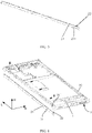
FIG 1 is a schematic structural diagram of a curved screen assembly according to an embodiment of this utility model; -
FIG. 2 is a cut-away view of a curved screen assembly according to an embodiment of this utility model; -
FIG. 3 is a schematic structural diagram of a first supporting component in a curved screen assembly according to an embodiment of this utility model; -
FIG. 4 is an exploded view of a first supporting component and a middle frame in a curved screen assembly according to an embodiment of this utility model; -
FIG. 5 is an exploded view of a first supporting component and a middle frame in a curved screen assembly according to an embodiment of this utility model when viewed in another direction; -
FIG. 6 is a cut-away view of a first supporting component in a curved screen assembly according to an embodiment of this utility model; -
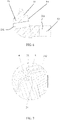
FIG. 7 is an enlarged view of position A inFIG. 2 ; -
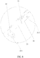
FIG. 8 is an enlarged view of position B inFIG. 5 ; -
FIG. 9 is a schematic structural diagram of a first tilted face and a second tilted face in a curved screen assembly according to an embodiment of this utility model; -
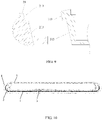
FIG. 10 is an internal schematic structural diagram of a curved screen assembly according to an embodiment of this utility model; and -
FIG. 11 is an assembling flowchart of a curved screen assembly according to an embodiment of this utility model. -
- 1. curved display screen;
- 11. first arc-shaped face;
- 12. second arc-shaped face;
- 2. first supporting component;
- 21. supporting body;
- 211. first supporting face;
- 212. second screw hole;
- 213. first tilted face;
- 22. connecting portion;
221. first screw hole; - 23. position defining portion;
- 24. boss;
- 25. glue overflow groove;
- 21. supporting body;
- 3. middle frame;
- 31. middle frame body;
- 311. recess;
- 312. fitting portion;
- 313. second tilted face;
- 32. second supporting component;
321. second supporting face;
- 31. middle frame body;
- 4. cover plate; and
- 5. housing.
- The accompanying drawings herein are incorporated into this specification and form a part of this specification, illustrate the embodiments conforming to this application, and are intended to explain the principles of this application together with this specification.
- Terms in the embodiments of this application are merely intended to describe specific embodiments of this application, and are not intended to limit this application.
- Electronic terminals such as mobile phones, tablet computers, and intelligent wearable devices have become indispensable objects nowadays. They enrich life and improve life quality. In the era of rapid development of science and technology, people not only require electronic terminals to have good performance, but also put forward high requirements for appearance of electronic terminals. Taking mobile phones as an example, from keypad mobile phones to touch-screen mobile phones, to large size mobile phones and today's most popular "full-screen" mobile phones, user experience is always a consideration.
- To further improve user experience, a
curved display screen 1 comes up in the prior art. Thecurved display screen 1 has an arc-shaped portion, effectively increasing a display area, improving a screen-to-body ratio of an electronic terminal, and better meeting people's visual demands. - With increasingly mature
curved display screen 1 technologies,curved display screens 1 have developed from those with small bending angle at the beginning to "waterfall screens" with a bending angle of nearly 90°. Some existingcurved display screens 1 even have a bending angle of more than 90°. However, as shown inFIG. 1 , when acurved display screen 1 and ahousing 5 are being assembled, the arc-shaped portion will be retracted because thecurved display screen 1 has a bending angle greater than 90°, thereby leading to a hollow space at the location of the arc-shaped portion without any support and protection, and resulting in that thecurved display screen 1 is vulnerable to damage, less reliable, or other problems. - To guarantee reliability of the
curved display screen 1, as shown inFIG. 2 , this embodiment provides a curved screen assembly. The curved screen assembly includes acurved display screen 1, a first supportingcomponent 2 and amiddle frame 3, where the first supportingcomponent 2 and themiddle frame 3 are both located at the inner surface of thecurved display screen 1. - The
curved display screen 1 has a first arc-shapedface 11 and a second arc-shapedface 12. Specifically, the first supportingcomponent 2 is located between themiddle frame 3 and the first arc-shapedface 11, and the first supportingcomponent 2 is provided with a first supportingface 211, where the first supportingface 211 matches the first arc-shapedface 11 in outline. Themiddle frame 3 is provided with a second supportingface 321, where the second supportingface 321 matches the second arc-shapedface 12 in outline. - With the design of the first supporting
face 211 and the second supportingface 321, the first arc-shapedface 11 and the second arc-shapedface 12 are well supported, which means that the location at which the retraction of thecurved display screen 1 occurs in assembling is supported. This prevents each of the first arc-shapedface 11 and the second arc-shapedface 12 from forming a hollow space and being vulnerable to damage, effectively protecting the first arc-shapedface 11 and the second arc-shapedface 12, and improving reliability of the curved screen assembly. - In the assembly of the
curved display screen 1, when the first supportingcomponent 2, themiddle frame 3, and thecurved display screen 1 are assembled, the standalone first supportingcomponent 2 and the design structure with a second supportingface 321 provided on themiddle frame 3 avoid the need to provide a supporting structural member on each side of themiddle frame 3, in order to support the first arc-shapedface 11 and the second arc-shapedface 12, effectively reducing errors in assembling themiddle frame 3, and better guaranteeing stability of themiddle frame 3 after assembling. Also, the manner to provide a detachable supporting structural member on one side optimizes the assembling process and improves assembling efficiency. - The first supporting
component 2 may be directly disposed between the first arc-shapedface 11 and themiddle frame 3, and in dependence on dimensional fits between the components and parts, thecurved display screen 1, the first supportingcomponent 2 and themiddle frame 3 are assembled. Alternatively, to guarantee the firmness of connection between the first supportingcomponent 2 and themiddle frame 3, the first supportingcomponent 2 may also be connected to themiddle frame 3 by bonding, welding, or the like. To facilitate maintenance and repair of components and parts, this embodiment provides a method for connecting the first supportingcomponent 2 to themiddle frame 3, where the first supportingcomponent 2 is connected to themiddle frame 3 in a detachable manner. A detachable connection method may include screw fastening, clamping, or the like. - As shown in
FIG. 3 , specifically in this embodiment, the first supportingcomponent 2 includes a supportingbody 21 provided with the first supportingface 211. The supportingbody 21 is located between the first arc-shapedface 11 and amiddle frame body 31. An end face of the supportingbody 21 facing themiddle frame 3 extends outward to form a connectingportion 22, and the connectingportion 22 is connected to themiddle frame 3 in a detachable manner. Further, the end face of the supportingbody 21 facing themiddle frame 3 extends outward to form the connectingportion 22, which means that the connectingportion 22 protrudes from the end face of the supportingbody 21. This exposed connection structure design facilitates observation and capture for assembling, and better facilitates the detachable connection between themiddle frame 3 and the connectingportion 22. In addition, this structural design forms the integrated first supportingcomponent 2, improving structural strength of the connectingportion 22 and facilitating processing of the first supportingcomponent 2. - As shown in
FIG. 4 , in this embodiment, themiddle frame 3 includes themiddle frame body 31 and a second supportingcomponent 32. To reduce errors in assembling themiddle frame 3, the second supportingcomponent 32 is integrally molded with themiddle frame body 31, and the integrated structural design facilitates processing of themiddle frame 3 and simplifies the assembling process by eliminating the need for subsequent assembling. - Referring to
FIG. 4 again, in this embodiment, to better facilitate the assembling of themiddle frame 3, themiddle frame body 31 is provided with arecess 311, and therecess 311 limits and fits the connectingportion 22. Design of therecess 311 facilitates position defining of themiddle frame 3. Further, in a height direction H of themiddle frame 3, a depth of therecess 311 may be less than a height of the connectingportion 22. To prevent an end of themiddle frame 3 connected to the connectingportion 22 from upwarping and affecting the support and protection effects of the second supportingface 321 on the second arc-shapedface 12, the depth of therecess 311 is greater than or equal to the height of the connectingportion 22, so that the entire connectingportion 22 is located in therecess 311 after themiddle frame 3 is assembled with the connectingportion 22. In addition, for therecess 311 with a greater depth, in design of themiddle frame 3, there is no need to consider influence of the height of the connectingportion 22. - Further, to improve the firmness of connection between the
middle frame 3 and the first supportingcomponent 2, the supportingbody 21 is connected to themiddle frame body 31 in a detachable manner, and the supportingbody 21 may be connected to themiddle frame body 31 by means of screw fastening, clamping, or the like. - As shown in
FIG. 5 andFIG. 6 , in this embodiment, the supportingbody 21 and the connectingportion 22 may both be connected to themiddle frame body 31 by means of screw fastening. The screw fastening can guarantee the firmness of connections among components and parts. Specifically, the connectingportion 22 is provided with afirst screw hole 221, and the supportingbody 21 is provided with asecond screw hole 212. The screw holes may be opened in a plurality of directions in the supportingbody 21 and the connectingportion 22. To facilitate assembling of screws and reduce difficulty of making the screw holes, an axis of thefirst screw hole 221 is arranged along a height direction H of themiddle frame 3, and an axis of thesecond screw hole 212 is arranged along a width direction W of themiddle frame 3. This method also facilitates screw-in of screws when themiddle frame 3 is being fastened, improving assembling efficiency. - To prevent excessive assembling of the
middle frame 3 in the assembling process and prevent damage thereby caused to thecurved display screen 1, as shown inFIG. 7 , in this embodiment, the first supportingcomponent 2 further includes aposition defining portion 23, and the supportingbody 21 is provided with theposition defining portion 23. Themiddle frame body 31 is provided with afitting portion 312, and thefitting portion 312 limits and fits theposition defining portion 23. When themiddle frame 3 is being assembled, theposition defining portion 23 is used to define a position and size for assembling themiddle frame 3 with the first supportingcomponent 2. After thefitting portion 312 fits theposition defining portion 23, assembling of themiddle frame 3 may be stopped to guarantee that themiddle frame 3 will not squeeze thecurved display screen 1, reducing a damage rate. - The
position defining portion 23 has a plurality of design structures. For example, theposition defining portion 23 may be a magnetic component, themiddle frame body 31 is provided with another magnetic component or an iron plate, and in assembling of themiddle frame 3, when theposition defining portion 23 completely and magnetically mates with thefitting portion 312, the assembling is in place; or, theposition defining portion 23 and thefitting portion 312 are both raised structures, and when theposition defining portion 23 is aligned with thefitting portion 312 in height, the assembling is in place. To better facilitate position defining, as shown inFIG. 8 , this embodiment provides a design structure of theposition defining portion 23 and thefitting portion 312. Specifically, the end face of the supportingbody 21 facing themiddle frame 3 extends outward to form aboss 24, and the end face of the supportingbody 21 facing themiddle frame 3 and theboss 24 together form theposition defining portion 23, so that theposition defining portion 23 is a stepped structure. An end face of themiddle frame body 31 facing theboss 24 extends outward to form thefitting portion 312. When themiddle frame 3 is being assembled, due to theposition defining portion 23 with the stepped structural design, themiddle frame body 31 cannot move further toward the direction of thecurved display screen 1 after thefitting portion 312 fully fits onto a step face of theposition defining portion 23, thereby preventing themiddle frame 3 from squeezing thecurved display screen 1. - In the height direction H of the
middle frame 3, the end face of the supportingbody 21 facing themiddle frame body 31 and an end face of theboss 24 facing themiddle frame body 31 may both be a vertical plane. As shown inFIG. 9 , specifically in this embodiment, to improve assembling efficiency and reduce assembling difficulty, the end face of the supportingbody 21 facing themiddle frame 3 and the end face of theboss 24 facing themiddle frame 3 are both a first tiltedface 213. The first tiltedface 213 is designed in such a way that, even if the first supportingface 211 does not completely fit with the first arc-shapedface 11 after the first supportingcomponent 2 is assembled, the first supportingface 211 may completely fit with the first arc-shapedface 11 under the action of themiddle frame 3 when themiddle frame 3 is assembled. Further, to improve stability of pre-assembling of themiddle frame 3 with the first supportingcomponent 2 and facilitate a next screw fastening procedure, the end face of themiddle frame body 31 facing theboss 24 and an end face of thefitting portion 312 facing theboss 24 are both a second tiltedface 313, and the first tiltedface 213 is parallel to the second tiltedface 313. The first tiltedface 213 fits the second tiltedface 313 to improve frictional resistance between the first supportingcomponent 2 and themiddle frame 3, preventing motion of the first supportingcomponent 2 relative to themiddle frame 3. Moreover, compared with vertical faces, tilted faces has lower design process requirements, and can achieve stable assembling of the first supportingcomponent 2 with themiddle frame 3 without guaranteeing full fitting between contact faces. - As shown in
FIG. 10 , in this embodiment, the curved screen assembly further includes acover plate 4 and ahousing 5. Thecurved display screen 1 fits onto a surface of thecover plate 4, and thecurved display screen 1 matches thecover plate 4 in outline. Thehousing 5 and thecover plate 4 are connected to each other at the edge, so that thehousing 5 and thecover plate 4 enclose an accommodating chamber. Thecurved display screen 1, the first supportingcomponent 2, and themiddle frame 3 are all located in the accommodating chamber. This structural design, which enables themiddle frame 3 to be hidden in the accommodating chamber formed by thehousing 5 and thecover plate 4, makes the curved screen assembly integrated, thereby improving visual aesthetics of appearance. - The
middle frame 3 is provided with a glue layer or a glue dispensing space to stick thehousing 5. Thehousing 5 may fit onto themiddle frame 3 by using the glue layer. Further, joints between thecover plate 4 and thehousing 5 are arranged to transit smoothly. The joints at edges of thecover plate 4 and thehousing 5 may be filled with embedded threads by using a process such as external caulking glue, to reduce seams in appearance of the curved screen assembly, improving the appearance of the curved screen assembly. - In addition, in processing technology of the
middle frame 3, the hiddenmiddle frame 3 may be completely manufactured with a low-cost process, such as aluminum die casting, because there is no need to consider an appearance effect, thereby reducing manufacturing costs of structural members of the device. A hidden design of themiddle frame 3 can also simplify assembling procedures and improve assembling efficiency. - As shown in
FIG. 11 , in this embodiment, a method for assembling the curved screen assembly is as follows: - SOI: Assemble the
cover plate 4 with thecurved display screen 1 first. - S03: Use a fixture to pre-fasten the first supporting
component 2 to the first arc-shapedface 11 by using foam tape or any other flexible binding material. - S05: Obliquely put in the
middle frame 3, so that the second supportingface 321 fully fits onto the second arc-shapedface 12, and lay themiddle frame 3 flat after themiddle frame 3 is in place, so that themiddle frame 3 fits the pre-fastened first supportingcomponent 2. - S07: Tighten screws to finally fasten the
middle frame 3 to the first supportingcomponent 2. - S09: Cover the
housing 5 with thecover plate 4, and connect thehousing 5 and thecover plate 4 by glue at the joint. - The foregoing connection methods may be separately used or combined according to an actual internal space of the
curved display screen 1 assembly. In addition to the foregoing connection methods, any other method for fastening components and parts may be used as long as requirements for fastening components and parts are met. - As shown in
FIG. 7 andFIG. 9 , in this embodiment, the first supportingcomponent 2 and the second supportingcomponent 32 are both provided with aglue overflow groove 25. Joints between thehousing 5 and thecover plate 4 are arranged opposite theglue overflow grooves 25. Theglue overflow grooves 25 can collect excess glue at the joints between thehousing 5 and thecover plate 4, preventing glue at the joints between thehousing 5 and thecover plate 4 from flowing to thecurved display screen 1 and leading to abnormal display of the screen. - This embodiment provides a terminal. The terminal includes the curved screen assembly according to any one of the foregoing embodiments. The terminal may be a mobile phone, a tablet computer, an intelligent wearable device, or the like.
- In this embodiment, the terminal includes but is not limited to an apparatus that is configured to receive/transmit communication signals through a wired line connection, for example, through a public switched telephone network (PSTN, Public Switched Telephone Network), a digital subscriber line (DSL, Digital Subscriber Line), a digital cable, a direct cable connection, and/or through a wireless interface for a cellular network, a wireless local area network (WLAN, Wireless Local Area Network), a digital television network such as a DVB-H network, a satellite network, an AM-FM broadcast transmitter, and/or another terminal.
- The terminal configured to communicate through a wireless interface may be referred to as a "wireless communication terminal", a "wireless terminal" or a "mobile terminal". Examples of the mobile terminal include but are not limited to a satellite or a cellular telephone; a personal communication system terminal capable of combining a cellular radio telephone and data processing, faxing and data communication capabilities; and a conventional laptop and/or palmtop receiver or another electronic apparatus including a radio telephone transceiver.
- The foregoing descriptions are merely preferred embodiments of this application, but are not intended to limit this application. Persons skilled in the art understand that this application may have various modifications and variations. Any modification, equivalent replacement, or improvement made without departing from the spirit and principle of this application shall fall within the protection scope of this application.
Claims (13)
- A curved screen assembly, comprising a curved display screen, a first supporting component, and a middle frame, wherein the curved display screen has a first arc-shaped face and a second arc-shaped face;the first supporting component is located between the middle frame and the first arc-shaped face, and provided with a first supporting face, where the first supporting face matches the first arc-shaped face in outline; andthe middle frame is provided with a second supporting face, where the second supporting face matches the second arc-shaped face in outline.
- The curved screen assembly according to claim 1, wherein the first supporting component comprises:a supporting body, where the supporting body is provided with the first supporting face; anda connecting portion, where an end face of the supporting body facing the middle frame extends outward to form the connecting portion, and the connecting portion is connected to the middle frame in a detachable manner.
- The curved screen assembly according to claim 2, wherein the middle frame comprises:a middle frame body, where the first supporting component is arranged between the middle frame body and the first arc-shaped face, and the connecting portion is connected to the middle frame body in a detachable manner; anda second supporting component, where the second supporting component is integrally molded with the middle frame body and provided with the second supporting face.
- The curved screen assembly according to claim 3, wherein the middle frame body is provided with a recess, and the recess limits and fits the connecting portion; wherein
in a height direction of the middle frame, a depth of the recess is greater than or equal to a height of the connecting portion. - The curved screen assembly according to claim 3, wherein the supporting body is connected to the middle frame body in a detachable manner.
- The curved screen assembly according to claim 5, wherein the connecting portion is provided with a first screw hole and the supporting body is provided with a second screw hole.
- The curved screen assembly according to claim 6, wherein an axis of the first screw hole is arranged along a height direction of the middle frame; and
an axis of the second screw hole is arranged along a width direction of the middle frame. - The curved screen assembly according to claim 3, wherein the first supporting component further comprises a position defining portion, and the supporting body is provided with the position defining portion; and
the middle frame body is provided with a fitting portion, and the fitting portion limits and fits the position defining portion. - The curved screen assembly according to claim 8, wherein the end face of the supporting body facing the middle frame extends outward to form a boss, and the end face of the supporting body facing the middle frame and the boss together form the position defining portion; and
an end face of the middle frame body facing the boss extends outward to form the fitting portion. - The curved screen assembly according to claim 9, wherein the end face of the supporting body facing the middle frame and an end face of the boss facing the middle frame are both a first tilted face;the end face of the middle frame body facing the boss and an end face of the fitting portion facing the boss are both a second tilted face; andthe first tilted face is parallel to the second tilted face.
- The curved screen assembly according to claim 3, further comprising:a cover plate, wherein the curved display screen fits onto a surface of the cover plate, and the curved display screen matches the cover plate in outline;a housing, wherein the housing and the cover plate are connected to each other at the edge, so that the housing and the cover plate enclose an accommodating chamber; andthe curved display screen, the first supporting component, and the middle frame are all located in the accommodating chamber.
- The curved screen assembly according to claim 11, wherein the first supporting component and the second supporting component are both provided with a glue overflow groove; and
joints between the housing and the cover plate are arranged opposite the glue overflow grooves. - A terminal, comprising a body, wherein the terminal further comprises the curved screen assembly according to any one of claims 1 to 12; and
the curved screen assembly is connected to the body.
Applications Claiming Priority (2)
| Application Number | Priority Date | Filing Date | Title |
|---|---|---|---|
| CN202020457460.8U CN212064060U (en) | 2020-04-01 | 2020-04-01 | Curved surface screen assembly and terminal |
| PCT/CN2021/082219 WO2021197116A1 (en) | 2020-04-01 | 2021-03-23 | Curved screen assembly and terminal |
Publications (3)
| Publication Number | Publication Date |
|---|---|
| EP4040763A1 true EP4040763A1 (en) | 2022-08-10 |
| EP4040763A4 EP4040763A4 (en) | 2023-01-11 |
| EP4040763B1 EP4040763B1 (en) | 2024-05-01 |
Family
ID=73539943
Family Applications (1)
| Application Number | Title | Priority Date | Filing Date |
|---|---|---|---|
| EP21779079.9A Active EP4040763B1 (en) | 2020-04-01 | 2021-03-23 | Curved screen assembly and terminal |
Country Status (4)
| Country | Link |
|---|---|
| US (1) | US12069195B2 (en) |
| EP (1) | EP4040763B1 (en) |
| CN (1) | CN212064060U (en) |
| WO (1) | WO2021197116A1 (en) |
Families Citing this family (5)
| Publication number | Priority date | Publication date | Assignee | Title |
|---|---|---|---|---|
| CN212064060U (en) | 2020-04-01 | 2020-12-01 | 华为技术有限公司 | Curved surface screen assembly and terminal |
| CN113067920B (en) * | 2021-03-10 | 2023-12-05 | 维沃移动通信有限公司 | an electronic device |
| CN113923280B (en) * | 2021-04-29 | 2022-11-18 | 荣耀终端有限公司 | Electronic device |
| CN114828500B (en) * | 2022-05-20 | 2023-12-29 | Oppo广东移动通信有限公司 | Electronic equipment, shell assembly and middle frame |
| US20240028090A1 (en) * | 2022-07-22 | 2024-01-25 | Honeywell International Inc. | Systems having a display unit and interchangeable bezel trim pieces for securing thereto |
Family Cites Families (7)
| Publication number | Priority date | Publication date | Assignee | Title |
|---|---|---|---|---|
| KR102410549B1 (en) * | 2015-04-09 | 2022-06-20 | 삼성전자주식회사 | Electronic Device with Bezel-less Screen |
| KR102678557B1 (en) * | 2017-02-23 | 2024-06-26 | 삼성전자주식회사 | Electronic device having supporting member with side antenna radiator |
| CN110035155A (en) * | 2019-04-19 | 2019-07-19 | Oppo(重庆)智能科技有限公司 | A kind of terminal device |
| CN210075346U (en) | 2019-08-29 | 2020-02-14 | Oppo(重庆)智能科技有限公司 | an electronic device |
| CN110572492A (en) | 2019-09-05 | 2019-12-13 | Oppo广东移动通信有限公司 | Electronic device |
| CN110648594A (en) * | 2019-09-29 | 2020-01-03 | 维沃移动通信有限公司 | Electronic device |
| CN212064060U (en) | 2020-04-01 | 2020-12-01 | 华为技术有限公司 | Curved surface screen assembly and terminal |
-
2020
- 2020-04-01 CN CN202020457460.8U patent/CN212064060U/en active Active
-
2021
- 2021-03-23 EP EP21779079.9A patent/EP4040763B1/en active Active
- 2021-03-23 US US17/773,846 patent/US12069195B2/en active Active
- 2021-03-23 WO PCT/CN2021/082219 patent/WO2021197116A1/en not_active Ceased
Also Published As
| Publication number | Publication date |
|---|---|
| EP4040763B1 (en) | 2024-05-01 |
| US12069195B2 (en) | 2024-08-20 |
| WO2021197116A1 (en) | 2021-10-07 |
| US20220400169A1 (en) | 2022-12-15 |
| EP4040763A4 (en) | 2023-01-11 |
| CN212064060U (en) | 2020-12-01 |
Similar Documents
| Publication | Publication Date | Title |
|---|---|---|
| US12069195B2 (en) | Curved screen assembly and terminal | |
| US12314082B2 (en) | Foldable terminal device including at least three housings coupled by rotating shafts | |
| CN207491003U (en) | Mobile terminal | |
| CN207910858U (en) | Mobile phone | |
| CN207491006U (en) | Mobile terminal | |
| CN207491004U (en) | Mobile terminal | |
| CN107770313A (en) | Mobile terminal and its camera module and bracket | |
| CN209375706U (en) | Electronic equipment and its electro-acoustic device bracket, integrated module of antenna and electro-acoustic device | |
| CN207802018U (en) | The holder of mobile terminal and its camera module | |
| CN107896261A (en) | Mobile terminal and display module thereof | |
| WO2023142629A9 (en) | Electronic device | |
| CN209659373U (en) | Mobile terminal and its shell component | |
| CN114828500B (en) | Electronic equipment, shell assembly and middle frame | |
| CN107749904A (en) | Mobile terminal and its camera module and bracket | |
| CN111641740A (en) | Electronic equipment | |
| CN209390123U (en) | A camera and terminal equipment | |
| HK40071118A (en) | Curved screen assembly and terminal | |
| WO2020199810A1 (en) | Mobile terminal and mounting drive module | |
| CN208079162U (en) | Mobile terminal | |
| CN207369098U (en) | Mobile terminal and its camera module and stent | |
| CN207410383U (en) | Mobile terminal and its camera module and bracket | |
| CN206650701U (en) | Housing unit and there is its terminal | |
| HK40071118B (en) | Curved screen assembly and terminal | |
| CN210016491U (en) | mobile terminal | |
| CN207802017U (en) | Mobile terminal and its camera module and holder |
Legal Events
| Date | Code | Title | Description |
|---|---|---|---|
| STAA | Information on the status of an ep patent application or granted ep patent |
Free format text: STATUS: THE INTERNATIONAL PUBLICATION HAS BEEN MADE |
|
| PUAI | Public reference made under article 153(3) epc to a published international application that has entered the european phase |
Free format text: ORIGINAL CODE: 0009012 |
|
| STAA | Information on the status of an ep patent application or granted ep patent |
Free format text: STATUS: REQUEST FOR EXAMINATION WAS MADE |
|
| 17P | Request for examination filed |
Effective date: 20220504 |
|
| AK | Designated contracting states |
Kind code of ref document: A1 Designated state(s): AL AT BE BG CH CY CZ DE DK EE ES FI FR GB GR HR HU IE IS IT LI LT LU LV MC MK MT NL NO PL PT RO RS SE SI SK SM TR |
|
| REG | Reference to a national code |
Ref country code: HK Ref legal event code: DE Ref document number: 40071118 Country of ref document: HK |
|
| A4 | Supplementary search report drawn up and despatched |
Effective date: 20221209 |
|
| RIC1 | Information provided on ipc code assigned before grant |
Ipc: G06F 1/16 20060101ALI20221205BHEP Ipc: H01L 27/32 20060101ALI20221205BHEP Ipc: H04M 1/02 20060101AFI20221205BHEP |
|
| DAV | Request for validation of the european patent (deleted) | ||
| DAX | Request for extension of the european patent (deleted) | ||
| STAA | Information on the status of an ep patent application or granted ep patent |
Free format text: STATUS: EXAMINATION IS IN PROGRESS |
|
| 17Q | First examination report despatched |
Effective date: 20230712 |
|
| GRAP | Despatch of communication of intention to grant a patent |
Free format text: ORIGINAL CODE: EPIDOSNIGR1 |
|
| STAA | Information on the status of an ep patent application or granted ep patent |
Free format text: STATUS: GRANT OF PATENT IS INTENDED |
|
| RIC1 | Information provided on ipc code assigned before grant |
Ipc: G06F 1/16 20060101ALI20231031BHEP Ipc: H04M 1/02 20060101AFI20231031BHEP |
|
| INTG | Intention to grant announced |
Effective date: 20231127 |
|
| RAP3 | Party data changed (applicant data changed or rights of an application transferred) |
Owner name: HONOR DEVICE CO., LTD. |
|
| GRAS | Grant fee paid |
Free format text: ORIGINAL CODE: EPIDOSNIGR3 |
|
| GRAA | (expected) grant |
Free format text: ORIGINAL CODE: 0009210 |
|
| STAA | Information on the status of an ep patent application or granted ep patent |
Free format text: STATUS: THE PATENT HAS BEEN GRANTED |
|
| AK | Designated contracting states |
Kind code of ref document: B1 Designated state(s): AL AT BE BG CH CY CZ DE DK EE ES FI FR GB GR HR HU IE IS IT LI LT LU LV MC MK MT NL NO PL PT RO RS SE SI SK SM TR |
|
| REG | Reference to a national code |
Ref country code: GB Ref legal event code: FG4D |
|
| REG | Reference to a national code |
Ref country code: CH Ref legal event code: EP |
|
| REG | Reference to a national code |
Ref country code: IE Ref legal event code: FG4D |
|
| REG | Reference to a national code |
Ref country code: DE Ref legal event code: R096 Ref document number: 602021012832 Country of ref document: DE |
|
| REG | Reference to a national code |
Ref country code: NL Ref legal event code: FP |
|
| REG | Reference to a national code |
Ref country code: LT Ref legal event code: MG9D |
|
| PG25 | Lapsed in a contracting state [announced via postgrant information from national office to epo] |
Ref country code: IS Free format text: LAPSE BECAUSE OF FAILURE TO SUBMIT A TRANSLATION OF THE DESCRIPTION OR TO PAY THE FEE WITHIN THE PRESCRIBED TIME-LIMIT Effective date: 20240901 |
|
| PG25 | Lapsed in a contracting state [announced via postgrant information from national office to epo] |
Ref country code: BG Free format text: LAPSE BECAUSE OF FAILURE TO SUBMIT A TRANSLATION OF THE DESCRIPTION OR TO PAY THE FEE WITHIN THE PRESCRIBED TIME-LIMIT Effective date: 20240501 |
|
| PG25 | Lapsed in a contracting state [announced via postgrant information from national office to epo] |
Ref country code: HR Free format text: LAPSE BECAUSE OF FAILURE TO SUBMIT A TRANSLATION OF THE DESCRIPTION OR TO PAY THE FEE WITHIN THE PRESCRIBED TIME-LIMIT Effective date: 20240501 Ref country code: FI Free format text: LAPSE BECAUSE OF FAILURE TO SUBMIT A TRANSLATION OF THE DESCRIPTION OR TO PAY THE FEE WITHIN THE PRESCRIBED TIME-LIMIT Effective date: 20240501 |
|
| PG25 | Lapsed in a contracting state [announced via postgrant information from national office to epo] |
Ref country code: GR Free format text: LAPSE BECAUSE OF FAILURE TO SUBMIT A TRANSLATION OF THE DESCRIPTION OR TO PAY THE FEE WITHIN THE PRESCRIBED TIME-LIMIT Effective date: 20240802 |
|
| PG25 | Lapsed in a contracting state [announced via postgrant information from national office to epo] |
Ref country code: PT Free format text: LAPSE BECAUSE OF FAILURE TO SUBMIT A TRANSLATION OF THE DESCRIPTION OR TO PAY THE FEE WITHIN THE PRESCRIBED TIME-LIMIT Effective date: 20240902 |
|
| REG | Reference to a national code |
Ref country code: AT Ref legal event code: MK05 Ref document number: 1683937 Country of ref document: AT Kind code of ref document: T Effective date: 20240501 |
|
| PG25 | Lapsed in a contracting state [announced via postgrant information from national office to epo] |
Ref country code: ES Free format text: LAPSE BECAUSE OF FAILURE TO SUBMIT A TRANSLATION OF THE DESCRIPTION OR TO PAY THE FEE WITHIN THE PRESCRIBED TIME-LIMIT Effective date: 20240501 |
|
| PG25 | Lapsed in a contracting state [announced via postgrant information from national office to epo] |
Ref country code: AT Free format text: LAPSE BECAUSE OF FAILURE TO SUBMIT A TRANSLATION OF THE DESCRIPTION OR TO PAY THE FEE WITHIN THE PRESCRIBED TIME-LIMIT Effective date: 20240501 |
|
| PG25 | Lapsed in a contracting state [announced via postgrant information from national office to epo] |
Ref country code: PL Free format text: LAPSE BECAUSE OF FAILURE TO SUBMIT A TRANSLATION OF THE DESCRIPTION OR TO PAY THE FEE WITHIN THE PRESCRIBED TIME-LIMIT Effective date: 20240501 |
|
| PG25 | Lapsed in a contracting state [announced via postgrant information from national office to epo] |
Ref country code: LV Free format text: LAPSE BECAUSE OF FAILURE TO SUBMIT A TRANSLATION OF THE DESCRIPTION OR TO PAY THE FEE WITHIN THE PRESCRIBED TIME-LIMIT Effective date: 20240501 |
|
| PG25 | Lapsed in a contracting state [announced via postgrant information from national office to epo] |
Ref country code: PT Free format text: LAPSE BECAUSE OF FAILURE TO SUBMIT A TRANSLATION OF THE DESCRIPTION OR TO PAY THE FEE WITHIN THE PRESCRIBED TIME-LIMIT Effective date: 20240902 Ref country code: PL Free format text: LAPSE BECAUSE OF FAILURE TO SUBMIT A TRANSLATION OF THE DESCRIPTION OR TO PAY THE FEE WITHIN THE PRESCRIBED TIME-LIMIT Effective date: 20240501 Ref country code: NO Free format text: LAPSE BECAUSE OF FAILURE TO SUBMIT A TRANSLATION OF THE DESCRIPTION OR TO PAY THE FEE WITHIN THE PRESCRIBED TIME-LIMIT Effective date: 20240801 Ref country code: LV Free format text: LAPSE BECAUSE OF FAILURE TO SUBMIT A TRANSLATION OF THE DESCRIPTION OR TO PAY THE FEE WITHIN THE PRESCRIBED TIME-LIMIT Effective date: 20240501 Ref country code: IS Free format text: LAPSE BECAUSE OF FAILURE TO SUBMIT A TRANSLATION OF THE DESCRIPTION OR TO PAY THE FEE WITHIN THE PRESCRIBED TIME-LIMIT Effective date: 20240901 Ref country code: HR Free format text: LAPSE BECAUSE OF FAILURE TO SUBMIT A TRANSLATION OF THE DESCRIPTION OR TO PAY THE FEE WITHIN THE PRESCRIBED TIME-LIMIT Effective date: 20240501 Ref country code: GR Free format text: LAPSE BECAUSE OF FAILURE TO SUBMIT A TRANSLATION OF THE DESCRIPTION OR TO PAY THE FEE WITHIN THE PRESCRIBED TIME-LIMIT Effective date: 20240802 Ref country code: FI Free format text: LAPSE BECAUSE OF FAILURE TO SUBMIT A TRANSLATION OF THE DESCRIPTION OR TO PAY THE FEE WITHIN THE PRESCRIBED TIME-LIMIT Effective date: 20240501 Ref country code: ES Free format text: LAPSE BECAUSE OF FAILURE TO SUBMIT A TRANSLATION OF THE DESCRIPTION OR TO PAY THE FEE WITHIN THE PRESCRIBED TIME-LIMIT Effective date: 20240501 Ref country code: BG Free format text: LAPSE BECAUSE OF FAILURE TO SUBMIT A TRANSLATION OF THE DESCRIPTION OR TO PAY THE FEE WITHIN THE PRESCRIBED TIME-LIMIT Effective date: 20240501 Ref country code: AT Free format text: LAPSE BECAUSE OF FAILURE TO SUBMIT A TRANSLATION OF THE DESCRIPTION OR TO PAY THE FEE WITHIN THE PRESCRIBED TIME-LIMIT Effective date: 20240501 Ref country code: RS Free format text: LAPSE BECAUSE OF FAILURE TO SUBMIT A TRANSLATION OF THE DESCRIPTION OR TO PAY THE FEE WITHIN THE PRESCRIBED TIME-LIMIT Effective date: 20240801 |
|
| PG25 | Lapsed in a contracting state [announced via postgrant information from national office to epo] |
Ref country code: DK Free format text: LAPSE BECAUSE OF FAILURE TO SUBMIT A TRANSLATION OF THE DESCRIPTION OR TO PAY THE FEE WITHIN THE PRESCRIBED TIME-LIMIT Effective date: 20240501 |
|
| PG25 | Lapsed in a contracting state [announced via postgrant information from national office to epo] |
Ref country code: EE Free format text: LAPSE BECAUSE OF FAILURE TO SUBMIT A TRANSLATION OF THE DESCRIPTION OR TO PAY THE FEE WITHIN THE PRESCRIBED TIME-LIMIT Effective date: 20240501 |
|
| PG25 | Lapsed in a contracting state [announced via postgrant information from national office to epo] |
Ref country code: CZ Free format text: LAPSE BECAUSE OF FAILURE TO SUBMIT A TRANSLATION OF THE DESCRIPTION OR TO PAY THE FEE WITHIN THE PRESCRIBED TIME-LIMIT Effective date: 20240501 |
|
| PG25 | Lapsed in a contracting state [announced via postgrant information from national office to epo] |
Ref country code: RO Free format text: LAPSE BECAUSE OF FAILURE TO SUBMIT A TRANSLATION OF THE DESCRIPTION OR TO PAY THE FEE WITHIN THE PRESCRIBED TIME-LIMIT Effective date: 20240501 Ref country code: SK Free format text: LAPSE BECAUSE OF FAILURE TO SUBMIT A TRANSLATION OF THE DESCRIPTION OR TO PAY THE FEE WITHIN THE PRESCRIBED TIME-LIMIT Effective date: 20240501 |
|
| PG25 | Lapsed in a contracting state [announced via postgrant information from national office to epo] |
Ref country code: SM Free format text: LAPSE BECAUSE OF FAILURE TO SUBMIT A TRANSLATION OF THE DESCRIPTION OR TO PAY THE FEE WITHIN THE PRESCRIBED TIME-LIMIT Effective date: 20240501 |
|
| PG25 | Lapsed in a contracting state [announced via postgrant information from national office to epo] |
Ref country code: SM Free format text: LAPSE BECAUSE OF FAILURE TO SUBMIT A TRANSLATION OF THE DESCRIPTION OR TO PAY THE FEE WITHIN THE PRESCRIBED TIME-LIMIT Effective date: 20240501 Ref country code: SK Free format text: LAPSE BECAUSE OF FAILURE TO SUBMIT A TRANSLATION OF THE DESCRIPTION OR TO PAY THE FEE WITHIN THE PRESCRIBED TIME-LIMIT Effective date: 20240501 Ref country code: RO Free format text: LAPSE BECAUSE OF FAILURE TO SUBMIT A TRANSLATION OF THE DESCRIPTION OR TO PAY THE FEE WITHIN THE PRESCRIBED TIME-LIMIT Effective date: 20240501 Ref country code: EE Free format text: LAPSE BECAUSE OF FAILURE TO SUBMIT A TRANSLATION OF THE DESCRIPTION OR TO PAY THE FEE WITHIN THE PRESCRIBED TIME-LIMIT Effective date: 20240501 Ref country code: DK Free format text: LAPSE BECAUSE OF FAILURE TO SUBMIT A TRANSLATION OF THE DESCRIPTION OR TO PAY THE FEE WITHIN THE PRESCRIBED TIME-LIMIT Effective date: 20240501 Ref country code: CZ Free format text: LAPSE BECAUSE OF FAILURE TO SUBMIT A TRANSLATION OF THE DESCRIPTION OR TO PAY THE FEE WITHIN THE PRESCRIBED TIME-LIMIT Effective date: 20240501 |
|
| REG | Reference to a national code |
Ref country code: DE Ref legal event code: R097 Ref document number: 602021012832 Country of ref document: DE |
|
| PG25 | Lapsed in a contracting state [announced via postgrant information from national office to epo] |
Ref country code: IT Free format text: LAPSE BECAUSE OF FAILURE TO SUBMIT A TRANSLATION OF THE DESCRIPTION OR TO PAY THE FEE WITHIN THE PRESCRIBED TIME-LIMIT Effective date: 20240501 |
|
| PLBE | No opposition filed within time limit |
Free format text: ORIGINAL CODE: 0009261 |
|
| STAA | Information on the status of an ep patent application or granted ep patent |
Free format text: STATUS: NO OPPOSITION FILED WITHIN TIME LIMIT |
|
| 26N | No opposition filed |
Effective date: 20250204 |
|
| PG25 | Lapsed in a contracting state [announced via postgrant information from national office to epo] |
Ref country code: SI Free format text: LAPSE BECAUSE OF FAILURE TO SUBMIT A TRANSLATION OF THE DESCRIPTION OR TO PAY THE FEE WITHIN THE PRESCRIBED TIME-LIMIT Effective date: 20240501 |
|
| PG25 | Lapsed in a contracting state [announced via postgrant information from national office to epo] |
Ref country code: SE Free format text: LAPSE BECAUSE OF FAILURE TO SUBMIT A TRANSLATION OF THE DESCRIPTION OR TO PAY THE FEE WITHIN THE PRESCRIBED TIME-LIMIT Effective date: 20240501 |
|
| PG25 | Lapsed in a contracting state [announced via postgrant information from national office to epo] |
Ref country code: MC Free format text: LAPSE BECAUSE OF FAILURE TO SUBMIT A TRANSLATION OF THE DESCRIPTION OR TO PAY THE FEE WITHIN THE PRESCRIBED TIME-LIMIT Effective date: 20240501 |
|
| REG | Reference to a national code |
Ref country code: CH Ref legal event code: H13 Free format text: ST27 STATUS EVENT CODE: U-0-0-H10-H13 (AS PROVIDED BY THE NATIONAL OFFICE) Effective date: 20251023 |
|
| PG25 | Lapsed in a contracting state [announced via postgrant information from national office to epo] |
Ref country code: LU Free format text: LAPSE BECAUSE OF NON-PAYMENT OF DUE FEES Effective date: 20250323 |
|
| REG | Reference to a national code |
Ref country code: BE Ref legal event code: MM Effective date: 20250331 |
|
| PG25 | Lapsed in a contracting state [announced via postgrant information from national office to epo] |
Ref country code: FR Free format text: LAPSE BECAUSE OF NON-PAYMENT OF DUE FEES Effective date: 20250331 |
|
| PG25 | Lapsed in a contracting state [announced via postgrant information from national office to epo] |
Ref country code: BE Free format text: LAPSE BECAUSE OF NON-PAYMENT OF DUE FEES Effective date: 20250331 |
|
| PG25 | Lapsed in a contracting state [announced via postgrant information from national office to epo] |
Ref country code: CH Free format text: LAPSE BECAUSE OF NON-PAYMENT OF DUE FEES Effective date: 20250331 |
|
| PG25 | Lapsed in a contracting state [announced via postgrant information from national office to epo] |
Ref country code: IE Free format text: LAPSE BECAUSE OF NON-PAYMENT OF DUE FEES Effective date: 20250323 |
|
| PGFP | Annual fee paid to national office [announced via postgrant information from national office to epo] |
Ref country code: NL Payment date: 20260213 Year of fee payment: 6 |
|
| PGFP | Annual fee paid to national office [announced via postgrant information from national office to epo] |
Ref country code: GB Payment date: 20260202 Year of fee payment: 6 |
|
| PGFP | Annual fee paid to national office [announced via postgrant information from national office to epo] |
Ref country code: DE Payment date: 20260204 Year of fee payment: 6 |