EP4040736B1 - Système, dispositif et procédé de transfert de données entre deux réseaux - Google Patents
Système, dispositif et procédé de transfert de données entre deux réseaux Download PDFInfo
- Publication number
- EP4040736B1 EP4040736B1 EP21155818.4A EP21155818A EP4040736B1 EP 4040736 B1 EP4040736 B1 EP 4040736B1 EP 21155818 A EP21155818 A EP 21155818A EP 4040736 B1 EP4040736 B1 EP 4040736B1
- Authority
- EP
- European Patent Office
- Prior art keywords
- data
- radio channels
- wireless network
- wired network
- network
- Prior art date
- Legal status (The legal status is an assumption and is not a legal conclusion. Google has not performed a legal analysis and makes no representation as to the accuracy of the status listed.)
- Active
Links
Images

Classifications
-
- H—ELECTRICITY
- H04—ELECTRIC COMMUNICATION TECHNIQUE
- H04L—TRANSMISSION OF DIGITAL INFORMATION, e.g. TELEGRAPHIC COMMUNICATION
- H04L12/00—Data switching networks
- H04L12/28—Data switching networks characterised by path configuration, e.g. LAN [Local Area Networks] or WAN [Wide Area Networks]
- H04L12/2803—Home automation networks
- H04L12/283—Processing of data at an internetworking point of a home automation network
- H04L12/2834—Switching of information between an external network and a home network
-
- H—ELECTRICITY
- H04—ELECTRIC COMMUNICATION TECHNIQUE
- H04L—TRANSMISSION OF DIGITAL INFORMATION, e.g. TELEGRAPHIC COMMUNICATION
- H04L12/00—Data switching networks
- H04L12/28—Data switching networks characterised by path configuration, e.g. LAN [Local Area Networks] or WAN [Wide Area Networks]
- H04L12/40—Bus networks
- H04L12/40169—Flexible bus arrangements
- H04L12/40176—Flexible bus arrangements involving redundancy
- H04L12/40195—Flexible bus arrangements involving redundancy by using a plurality of nodes
-
- H—ELECTRICITY
- H04—ELECTRIC COMMUNICATION TECHNIQUE
- H04L—TRANSMISSION OF DIGITAL INFORMATION, e.g. TELEGRAPHIC COMMUNICATION
- H04L12/00—Data switching networks
- H04L12/28—Data switching networks characterised by path configuration, e.g. LAN [Local Area Networks] or WAN [Wide Area Networks]
- H04L12/2803—Home automation networks
- H04L2012/284—Home automation networks characterised by the type of medium used
- H04L2012/2841—Wireless
Definitions
- the invention disclosed herein is in the field of data transmission between two networks, at least one of which is wireless.
- a dedicated device is typically provided that is connected to both networks and can transmit data from one of the networks to the other network.
- Such devices are called routers or gateways and are required to bridge technical differences between the two networks and, for example, to couple a wireless network to a wired network or in general to networks that use different hardware and/or different protocols.
- wireless networks often have to be coupled with wired networks.
- devices can communicate via disjoint radio channels.
- some devices communicate via one or more first radio channels
- other devices in the same network communicate via one or a plurality of second radio channels, the first and second radio channels comprising different frequencies that do not overlap.
- a concrete example of such differently communicating devices are on the one hand devices that are battery-operated and therefore only access their radio channels occasionally, for example cyclically, with these radio channels being operated at a low frequency and therefore being more suitable for slow data transmission.
- devices that have a permanent power supply can often access their radio channels, which radio channels operate at a higher frequency and are suitable for faster data transmission.
- a gateway that couples such a wirelessly operated network to a second network must therefore be able to transmit data on different frequencies from one network to the other.
- the data packets also referred to as telegrams
- a duty cycle indicates the ratio in which the device transmits during a given period of time. In many places there are legal regulations according to which a device must not exceed a specific duty cycle when transmitting on a specific frequency.
- the present invention is therefore based on the object of enabling a link between two networks that ensures fast data transmission between the networks. From the patent application US2020205036 A1 a system with load balancing between radio channels is known.
- Embodiments of the invention relate to a system comprising: a wired network; a wireless network; a first device connected to the wired and wireless networks; and a second device connected to the wireless network and the first device, wherein the connection between the first and second devices is wired; wherein the first device is set up, in a first operating mode, to send data from the wired network to the wireless network on one or more first radio channels; wherein the second device is set up, in the first operating mode, to transmit data from the wired network to the wireless network on one or more second radio channels, the first radio channels being disjoint from the second radio channels; wherein the first device is set up to check whether a specified maximum permissible period of use of the first radio channels was reached by the first device within a fixed period of time that was just in the past, and wherein the first and the second device switch to a second operating mode in response to the achievement, in which the first device sends data from the wired network to the wireless network on the second radio channels and the second device sends data from the wire
- the first device is also set up, in the first operating mode, to read data from the wireless network on the first radio channels and to transmit the data to the wired network, and in the second operating mode to read data from the wireless network on the second radio channels and transmit the data to the wired network.
- the second device is also set up, in the first operating mode, to read data from the wireless network on the second radio channels and to transmit the data to the wired network, and in the second operating mode to read data from the wireless network on the first radio channels and transmit the data to the wired network.
- the second device is preferably set up to transmit data to the wired network via the first device.
- the first device is set up to determine whether data from the wired network is to be sent to the wireless network via the first or second radio channels.
- the first device is expediently set up to transmit data from the wired network to the second device if the data are to be sent via a radio channel other than the radio channel of a current operating mode of the first device.
- first device and the second device can be visible to devices from the wireless network and/or the wired network at the same address.
- Embodiments further include a method comprising: transmitting, by a first device in a first mode of operation, data from a wired network to a wireless network on one or more first radio channels; and transmitting, by a second device in the first mode of operation, data from the wired network to the wireless network on one or more second radio channels, the first radio channels being disjoint from the second radio channels; wherein the first device checks whether a predetermined maximum permissible period of use of the first radio channels has been reached by the first device within a fixed time period that has just passed, and wherein the first device and the second device switch to a second operating mode in response to the achievement, in which the first device sends data from the wired network to the wireless network on the second radio channels and the second device sends data from the wired network to the wireless network on the first radio channels.
- the method further comprises: reading, by the first device in the first operating mode, data from the wireless network on the first radio channels and transmitting the data to the wired network; and reading, by the first device in the second mode of operation, data from the wireless network on the second radio channels and transmitting the data to the wired network.
- the method further comprises: reading, by the second device in the first operating mode, data from the wireless network on the second radio channels and transmitting the data to the wired network; and reading, by the second device in the second operating mode, data from the wireless network on the first radio channels and transmitting the data to the wired network.
- the second device transmits data to the wired network via the first device.
- the method further includes: determining, by the first device, whether to transmit data from the wired network to the wireless network over the first or second radio channels.
- the method can also include: the first device transmitting data from the wired network to the second device if the data is to be sent via a radio channel other than the radio channel of a current operating mode of the first device.
- the method also includes: checking, by the second device, whether a predetermined maximum permissible usage time of the second radio channels has been reached by the second device within a fixed, recent period of time, and changing the operating modes of the first device and the second device in response to the To reach.
- Embodiments also relate to a computer-readable medium having instructions stored thereon that, when executed by a processor, perform any of the recited methods.
- a channel is understood to mean one or more radio channels. If a first channel is disjoint from a second channel, its radio channels run over frequencies which differ from, and in particular do not overlap with, the frequencies of the second channel. Data packets or telegrams are generally referred to as data.
- duty cycle is understood to mean a maximum (accumulated) time period in which data may be sent at a specific frequency within a time interval. The duty cycle can be viewed either as a percentage (e.g. 90% of an interval of one hour may be transmitted on frequency N) or as an absolute value (e.g. 45 minutes may be transmitted on frequency N in an interval of one hour).
- a device is understood as a device that is able to communicate in a network, for example any network-capable computer, mobile phone, printer, etc.
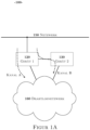
- FIG. Device 120 can be viewed as one of multiple devices coupled within network 150 .
- the first device 120 is connected to a second device 130 .
- This device 130 is also connected to the wireless network 160 .
- the connection between the two devices is preferably wired.
- the device 130 can also be connected to the wired network 150, but this is not required for the invention.
- the devices 120 and 130 serve as an interface between the two networks and are set up to transmit data from one of the networks to the other.
- the first device 120 receives data from the wired network 150.
- This data includes both data to be transmitted to the second network 160 on a first channel and data to be transmitted to the second network 160 on a second channel.
- the first and second channels are disjoint and thus use different frequencies that do not overlap or overlap between the first and second channels.
- the data of both channels are labeled "Channel A” and "Channel B".
- “Channel A” may relate to data to be sent at faster frequencies than "Channel B”.
- the first device 120 decides whether the received data should be sent via channel A or channel B.
- the channel may be derived from a format of the data, such as a flag, set appropriately by the sending device on network 150.
- the channel can be determined based on the destination address of the data.
- device 120 may be configured to maintain a table that maps the addresses of devices on wireless network 160 to the channel used by those devices. For example, such a table may be continually updated as data is received from devices on wireless network 160 at device 120; this possibility is referred to Figures 2A and 2 B explained. Receives the device 120 from the wired Network 150 data whose destination device is not listed in the table, a default value can be used for further transmission, i.e. channel A or channel B.
- the operating mode shown is that the first device 120 is set up to transmit data that is to be sent on channel A directly into the wireless network 160 .
- the device 120 transmits data that is to be sent on channel B to the second device 130 , from where the data are in turn sent to the wireless network 160 .
- Both devices 120 and 130 may contain technical means for converting wired to wireless protocols, for example by means of tunneling or encapsulations within the layer model (OSI); such conversions are at the discretion of those skilled in the art and their specific implementation is not part of the invention.
- OSI layer model
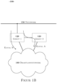
- Figure 1B 12 shows the operation of devices 120 and 130 in a second mode of operation.
- the first device 120 receives data from the wired network 150 that is to be sent to the wireless network 160 via channel A or channel B.
- the first device 120 is now used to send the data that is to be transmitted via channel B and forwards the data to be sent via channel A to the second device 130 .
- the tables already explained or also a format of the data can be used to determine the respective channel.
- the first device 120 can additionally check whether the data should be sent via both channel A and channel B, regardless of the operating mode (channel A or channel B). In this case, the first device 120 sends the data to the wireless network 160 over its channel and also to the second device 130, which also sends the data to the wireless network 160 over the other channel.
- This embodiment is advantageous when the data is to be sent to different devices on the wireless network 160, some of which receive on one channel and others receive on the other channel.
- An example scenario is battery powered Devices and devices connected to the domestic electrical system, for which disjunctive channels are provided and which in certain cases are intended to receive the same data
- the first and the second mode of operation are provided in order to avoid that one of the devices 120 and 130 reaches or exceeds a predetermined duty cycle on the respective channel used.
- Devices 120 and 130 can switch from the first to the second mode of operation and vice versa.
- both devices operate with an initial configuration, for example device 120 on channel A and device 130 on channel B, or vice versa.
- the initial configuration can be taken from the last operation of the two devices, or can be random or standard assignment.
- Each of the devices 120 and 130 is programmed with a duty cycle for the first channel and for the second channel, or has access to these values.
- each of the devices 120 and 130 can maintain a data structure, preferably a list, in which the transmission times already used per channel are stored.
- device 120 includes a first list for the first channel and a second list for the second channel. If a transmission process is completed on a channel, the device supplements the list that is assigned to this channel. For example, a time stamp for the start and end of the transmission process can simply be appended to the list (push), or the transmission duration can be appended after the end of the transmission process.
- the first device 120 When the first device 120 receives data from the wired network 150, after determining the channel to be used (see above, Figure 1A ) on whether the data should be sent to the wireless network 160 by the first device 120 or by the second device 130 .
- this is determined by comparing the channel currently being used by the first device 120 with the channel to be used for the data. If the channels differ, the first device 120 sends the data to the second device 130. However, if both channels are identical, the first device 120 checks whether its duty cycle for this channel has been reached. For example, the first device 120 accumulates the stored durations of Sends made for this channel in a period from the current time. The device 120 then checks whether this accumulated total duration is greater than the stored duty cycle. If this is the case, the first device 120 notifies the second device 130 and switches to the second operating mode. The second device 130 also changes operating mode in response to this notification.
- the first device 120 can additionally check in a special embodiment whether not only the channel of the first device 120 but also the channel of the second device 130 is to be used. If this is the case, the first device 120 sends the data both to the wireless network 160 and to the second device 130.
- the second device 130 Independent of the first device 120, the second device 130 also checks continuously or when receiving data for the wireless network 160 whether its duty cycle for the channel currently used by the second device 130 has been reached or exceeded. To do this, it proceeds analogously to the first device 120 and informs it when its duty cycle has been exceeded and changes the operating mode. In this way it is ensured that both devices always change the mode promptly, so that both devices operate different channels.
- the check that the duty cycle has been reached or exceeded can include a check that the duty cycle is approaching, for example by checking that a threshold value below the duty cycle has been exceeded.
- the check is preferably performed in response to a receipt of data from the wired network 150, since in this case a transmission via radio is imminent.
- the check can be carried out at regular intervals, independent of incoming data.
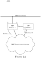
- Figure 2A 12 shows an operation of devices 120 and 130 in FIG Figure 1A mode of operation shown, with the data compared to that Figure 1A in the opposite direction, namely from the wireless network 160 into the wired network 150, are transferred. Since the first device 120 is operating on channel A in this mode of operation, it only reads channel A data from the wireless network 160, while the second device 130 reads channel B data. The first device 120 forwards the read data to the network 150, possibly after converting the protocols used. The second device 130 forwards read data to the network 150 via the first device 120 . Alternatively, the second device 130 can also transfer data to the network 150 via a direct connection (not shown).
- the advantage of a direct connection is that the processing of data is better divided between the first and second device.
- the advantage of doing without a direct connection is that the routing of data is simplified from the point of view of the devices in the wired network 150, since only the first device 120 can be controlled from there.
- the devices 120 and 130 preferably use the arrival of the respective data to update the tables already explained. To do this, the respective device checks whether a channel has already been entered in the table for a device that sent the data from the wireless network 160 or from the wired network 150, and whether this channel is identical to the current channel of this data or the device . If necessary, a new entry is made in the table or an existing entry is adjusted.
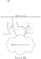
- Figure 2B additionally shows the operation of the devices 120 and 130 in the in Figure 1B mode of operation shown; both devices work on the same channels as in Figure 1B , and read data from the wireless network 160 on these channels.
- the further functioning of the two devices 120 and 130 follows the above explanations with regard to Figure 2A .
- the operation according to Figures 1A and 2A can take place simultaneously, provided that the first device 120 has appropriate transmission and reception means (antenna) that enable the simultaneous transmission and reception of data in and out of the wireless network 160 .
- the operation takes place according to Figure 1A independent (asynchronous) according to the operation Figure 2A .
- the operation according to Figures 1B and 2 B occur simultaneously and independently of each other.
- the invention avoids delays in the sending of packets that would occur without a change in operating mode as soon as a duty cycle is exceeded.
- the invention also avoids a higher outlay on hardware that would arise with a larger number of routers operating in parallel; the routing between the networks would also be more complex than with a single router according to the invention (first device) with a covert second device that is not visible to the wired network.
- the embodiments shown also offer the advantage of restricting losses of data packets (telegrams) on device 120 .
- This advantage arises because a significant portion of the data received by device 120 is transmitted directly to device 130 without conversion by device 120 . By dispensing with the conversion, the device 120 can immediately continue receiving and processing further data, so that losses are reduced.
- the possible duty cycle is distributed over two devices, so that the probability that the duty cycle will be reached at all during operation decreases.
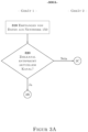
- Figures 3A , 3B and 3C show methods 300A, 300B and 300C according to the invention, which Figures 1A and 1B shown modes of operation of the devices 120 and 130 represent, ie the transmission of data from the wired network 150 in the wireless network 160.
- the individual steps are arranged in two columns; the steps in the left column are performed by the first device 120 , the steps in the right column are performed by the second device 130 . This is indicated by the headings "Device 1" and "Device 2" and is given in the Figures 3B and 3C highlighted by a vertical dividing line.
- the first device 120 receives data from the wired network 150.
- the device 120 then first determines the channel on which the data is to be sent into the wireless network 160, for example by looking up a table indicating which of the channels is to be used for a destination device of the data in the wireless network 160, or by interpreting a format of the data; such measures have already been described above.
- the first device 120 checks whether the target channel, ie the channel on which the received data is to be sent, corresponds to the channel used by the device 120 in its current operating mode. In this case, method 300A is performed in accordance with method 300B Figure 3B continued. Otherwise, method 300A follows method 300C Figure 3C continued. In a particular embodiment, both methods 300B and 300C can also be carried out, for example if the first device 120 determines in step 320 that the data should be sent via both channels.
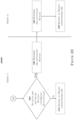
- FIG. 300B shows the method performed when the received data is to be sent on the channel of the first device 120.
- the first device checks whether a duty cycle has been exceeded. This check includes comparing a total duration of data transmissions made over the current channel within a set time interval elapsed at the current time with a predetermined fixed duty cycle value for this channel, for example a legally prescribed maximum permissible value. In one embodiment, this comparing includes accumulating all periods of time that have been transmitted on that channel within the past time interval. For example, the method can use a list of such time periods for this purpose, in which all time periods with associated time periods, in particular in the form of time stamps of the beginning and end of each data transmission, are stored.
- Such a list is maintained separately for each channel. If the received data is to be sent via the first channel A, for example, the comparison is carried out using the list maintained for the first channel A and the duty cycle value for this channel. If, on the other hand, the received data is to be sent via the second channel B, the comparison is carried out using the list kept for the second channel B and the duty cycle value for channel B. Carrying out the comparison includes, for example, determining the percentage of the accumulated total duration in the duty cycle value. If the duty cycle for the channel is undershot, it is therefore, for example, below a predetermined maximum permitted percentage, or below a predetermined threshold value, which is below the permitted duty cycle, the first device 120 sends the data in step 345 to the wireless network 160. A time stamp is preferably added to the list already explained at the beginning and end of this transmission process written for this channel.
- step 335 includes notifying the second device 130 of the change; For this purpose, the first device 120 sends a predefined data packet or other predefined message via the direct connection between the two devices. Step 335 also includes the transmission of the data to be sent to the second device 130.
- Method 300B continues at second device 130 .
- the second device 130 switches channels in response to the notification so that both devices are now using different channels again.
- the second device 130 sends the data to the wireless network 160 using the channel previously used by the first device 120.
- Figure 3C shows method 300C performed when in step 320 of method 300A/ Figure 3A it has been determined that the data from network 150 should be sent on a channel other than the current channel of the first device 120 or, according to a particular embodiment, on both channels.
- the method 300C begins at step 360 where the second device 130 determines whether the second device's current channel usage history is below its duty cycle for that channel. As already explained, the second device 130 also has a duty cycle for each of the two channels.
- the comparison of the previous usage with the duty cycle follows analogously to step 330 of the first one Device 120 implemented measures, so for example accumulation of previous usage times on the channel within a past at this time fixed predetermined interval, based on a list for this channel, which records the usage times in the form of time stamps.
- the second device 130 can already transmit the data to be sent with the transition from step 320 ( Figure 3A ) to step 360 ( Figure 3C ) received from the first device 120; alternatively, the transmission of the data from device 120 to device 130 can be made dependent on the result of the check in step 360, in that the data are only transmitted to device 130 if the duty cycle of this device has not been exceeded.
- the second device 130 sends the data to the wireless network 160 in step 375.
- the second device 130 preferably writes time stamps for the start and end of the transmission process the already mentioned list for this channel.
- the second device 130 changes from its current channel to the other channel in step 365, notified the first device from this measure and sends the data back to the first device 120. This also changes its channel in step 370; after these changes, both devices work on different channels again.
- the first device 120 sends the data over the switched channel to the wireless network 160 in step 380. This data can be received by the first device 120 from the second device 130 in step 370; alternatively, the first device 120 accesses the data from step 310.
- the start and end of the transmission process are preferably recorded in step 380 by the first device 120, for example in the form of time stamps, which are appended to a list for the current channel.
- All of the steps involved in sending data to wireless network 160 may include converting the data from a network 150 protocol or other format to a network 160 protocol or format as appropriate.
- methods include 300B and 300C, respectively Figures 3B and 3B Steps 330 and 360 to check whether a duty cycle has been exhausted; these steps are performed in response to receiving data at the respective device 120 or 130.
- This embodiment achieves the advantage that the number of checks is reduced compared to a regular, data-independent check, and that the risk of the duty cycles being exceeded is reduced.
- the check can also be carried out independently of the receipt of data, for example at regular intervals.
- Such an embodiment thus comprises only the sequence of steps 330, 335, 340 or 360, 365, 370, without data being received or sent immediately before or afterwards.
- This embodiment achieves the advantage that the channel change measures in both devices do not delay the data flow from the first network 150 to the second network 160 .
- the invention further encompasses embodiments in which the first device 120 checks both duty cycles.
- the first device 120 checks the duty cycle of its current channel, either in response to received data or periodically, and initiates the channel change on both devices if necessary.
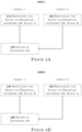
- the Figures 4A and 4B 12 show methods 400A and 400B that illustrate the operation of the methods shown in FIGS Figures 2A and 2B, respectively. This mode of operation affects the transmission of data from the wireless network 160 to the wired network 150.
- the first device 120 is set up to use a first channel A as the current channel.
- the device 120 only reads data from the wireless network that is sent on this channel.
- the second device 130 only reads data from the wireless network 160 which appears on the second B channel.
- the second device 130 transmits this data to the first device 120 via a direct connection.
- the first device 120 transmits the data it has read or the data received from the second device 130 to the network 150.
- step 420 does not involve the transmission of data from the second device 130 to the first device 120, but transmits the data of this channel directly to the network 150.
- Steps 410 and 420 can be used by the respective device to update a table that records which of the two channels is used by which of the transmitting devices in the wireless network 160 .
- the table thus maps devices to channels. This information can be taken from the received data in step 410 or 420, for example in the form of an IP address of the device in the wireless network 160 that sent the data, in connection with the current channel or the channel on which the data was sent to the first or second device can be received. Updating the table may include checking whether an entry already exists for the particular transmitting device of wireless network 160 and whether that entry reflects the current channel. The table is only adjusted in the event of a missing or deviating entry.
- the embodiments described here can be extended to more than two devices 120, 130.
- the invention thus enables efficient data transmission between two networks in both directions.
- a particular advantage is that the devices 120 and 130 operate on different channels and change channels under certain circumstances. This significantly speeds up the processing of the data in these devices and, in particular, ensures that specified channel restrictions (duty cycle) are observed.
- Another advantage is that after testing the duty cycle in one of the two devices, the test on the other device for the same channel does not have to be carried out as well - since the other device was working on the other channel up to this point the probability of both devices exceeding the duty cycle for the same channel is very low.
Landscapes
- Engineering & Computer Science (AREA)
- Automation & Control Theory (AREA)
- Computer Networks & Wireless Communication (AREA)
- Signal Processing (AREA)
- Computing Systems (AREA)
- Mobile Radio Communication Systems (AREA)
- Small-Scale Networks (AREA)
Claims (15)
- Système (100) comprenant :un réseau filaire (150) ;un réseau sans fil (160) ;un premier appareil (120), qui est relié avec les réseaux filaire et sans fil ; etun deuxième appareil (130), qui est relié avec le réseau sans fil et le premier appareil, dans lequel la liaison entre les premier et deuxième appareils est filaire ;dans lequel le premier appareil (120) est conçu pour envoyer, dans un premier mode de fonctionnement, des données provenant du réseau filaire au réseau sans fil sur un ou plusieurs premiers canaux radio ;dans lequel le deuxième appareil (130) est conçu pour envoyer, dans le premier mode de fonctionnement, des données provenant du réseau filaire au réseau sans fil sur un ou plusieurs deuxièmes canaux radio, dans lequel les premiers canaux radio sont distincts des deuxièmes canaux radio ;dans lequel le premier appareil (120) est conçu pour vérifier si une durée d'utilisation maximale admissible prédéterminée des premiers canaux radio par le premier appareil a été atteint dans une période fixe immédiatement précédente, et dans lequel, en tant que réponse au fait que cette durée a été atteinte, les premier et deuxième appareils passent dans un deuxième mode de fonctionnement dans lequel le premier appareil (120) envoie des données provenant du réseau filaire vers le réseau sans fil sur les deuxièmes canaux radio et le deuxième appareil (130) envoie des données provenant du réseau filaire au réseau sans fil sur les premiers canaux radio.
- Système selon la revendication 1, dans lequel le premier appareil est en outre conçu pour lire, dans le premier mode de fonctionnement, des données provenant du réseau sans fil sur les premiers canaux radio et pour transmettre ces données au réseau filaire et dans le deuxième mode de fonctionnement, pour lire les données provenant du réseau sans fil sur les deuxièmes canaux radio et pour transmettre ces données au réseau filaire.
- Système selon la revendication 1 ou 2, dans lequel le deuxième appareil est en outre conçu pour lire, dans le premier mode de fonctionnement, des données provenant du réseau sans fil sur les deuxièmes canaux radio et pour transmettre ces données au réseau filaire et, dans le deuxième mode de fonctionnement, pour lire des données provenant du réseau sans fil sur les premiers canaux radio et pour transmettre ces données au réseau filaire.
- Système selon la revendication 3, dans lequel le deuxième appareil est conçu pour transmettre des données au réseau filaire par l'intermédiaire du premier appareil.
- Système selon l'une des revendications 1 à 4, dans lequel le premier appareil est conçu pour déterminer si les données provenant du réseau filaire doivent être envoyées, par l'intermédiaire des premiers et/ou des deuxièmes canaux radio, au réseau sans fil.
- Système selon la revendication 5, dans lequel le premier appareil est conçu pour transmettre des données provenant du réseau filaire au deuxième appareil lorsque les données doivent être envoyées, par l'intermédiaire d'un autre canal radio que le canal radio d'un mode de fonctionnement actuel du premier appareil, plus particulièrement dans lequel la transmission a lieu en plus de l'envoi vers le réseau fil, si les données doivent être envoyées par l'intermédiaire des premiers et des deuxièmes canaux radio.
- Système selon l'une des revendications 1 à 6, dans lequel le premier appareil et le deuxième appareil sont visibles par des appareils du réseau sans fil et/ou du réseau filaire sous la même adresse.
- Procédé comprenant :l'envoi, par un premier appareil (120), dans un premier mode de fonctionnement, de données provenant d'un réseau filaire (150) vers un réseau sans fil (160) sur un ou plusieurs premiers canaux radio ; etl'envoi, par un deuxième appareil (130), dans le premier mode de fonctionnement, de données provenant du réseau filaire vers le réseau sans fil sur un ou plusieurs deuxièmes canaux radio, dans lequel les premiers canaux radio sont distincts des deuxièmes canaux radio ;dans lequel le premier appareil (120) vérifie si une durée d'utilisation maximale admissible des premiers canaux radio par le premier appareil a été atteint dans une période fixe immédiatement précédente et dans lequel le premier appareil (120) et le deuxième appareil (130), en réponse au fait que cette durée est atteinte, passent à un deuxième mode de fonctionnement dans lequel le premier appareil (120) envoie des données provenant du réseau filaire vers le réseau sans fil sur les deuxièmes canaux radio et le deuxième appareil (130) envoie des données provenant du réseau filaire vers le réseau sans fil sur les premiers canaux radio.
- Procédé selon la revendication 8, comprenant en outre :la lecture, par le premier appareil, dans le premier mode de fonctionnement, de données provenant du réseau sans fil sur les premiers canaux radio et transmission des données au réseau filaire ; etlecture, par le premier appareil, dans le deuxième mode de fonctionnement, de données provenant du réseau sans fil sur les deuxièmes canaux radio et transmission des données au réseau filaire.
- Procédé selon la revendication 8 ou 9, comprenant en outre :lecture, par le deuxième appareil, dans le premier mode de fonctionnement, de données provenant du réseau sans fil sur les deuxièmes canaux radio et transmission des données au réseau filaire ; etlecture, par le deuxième appareil, dans le deuxième mode de fonctionnement, de données provenant du réseau sans fil sur les premiers canaux radio et transmission des données au réseau filaire sur les premiers canaux radio et transmission des données au réseau filaire.
- Procédé selon la revendication 10, dans lequel le deuxième appareil transmet des données au réseau filaire par l'intermédiaire du premier appareil.
- Procédé selon l'une des revendications 8 à 11, comprenant en outre :
la détermination, par le premier appareil, si des données provenant du réseau filaire doivent être envoyées au réseau sans fil par l'intermédiaire des premiers et/ou deuxièmes canaux radio. - Procédé selon la revendication 12, comprenant en outre :
la transmission, par le premier appareil, de données provenant du réseau filaire au deuxième appareil lorsque les données doivent être envoyées par l'intermédiaire d'un autre canal radio en tant que canal radio d'un premier mode de fonctionnement d'un premier appareil, plus particulièrement dans lequel la transmission a lieu en plus de l'envoi vers le réseau sans fil si les données doivent être envoyées par l'intermédiaire des premiers et deuxièmes canaux radio. - Procédé selon l'une des revendications 8 à 13, comprenant en outre :
la vérification, par le deuxième appareil, si une durée d'utilisation maximale admissible des deuxièmes canaux radio par le deuxième appareil a été atteinte dans une période fixe immédiatement précédente et modification des modes de fonctionnement du premier appareil et du deuxième appareil en réponse au fait que cette durée a été atteinte. - Support lisible par un ordinateur avec des instructions enregistrées dessus qui, lorsqu'elles sont exécutées par un processeur, permettent d'exécuter le procédé selon l'une des revendications 8 à 14.
Priority Applications (1)
| Application Number | Priority Date | Filing Date | Title |
|---|---|---|---|
| EP21155818.4A EP4040736B1 (fr) | 2021-02-08 | 2021-02-08 | Système, dispositif et procédé de transfert de données entre deux réseaux |
Applications Claiming Priority (1)
| Application Number | Priority Date | Filing Date | Title |
|---|---|---|---|
| EP21155818.4A EP4040736B1 (fr) | 2021-02-08 | 2021-02-08 | Système, dispositif et procédé de transfert de données entre deux réseaux |
Publications (2)
| Publication Number | Publication Date |
|---|---|
| EP4040736A1 EP4040736A1 (fr) | 2022-08-10 |
| EP4040736B1 true EP4040736B1 (fr) | 2023-08-09 |
Family
ID=74572633
Family Applications (1)
| Application Number | Title | Priority Date | Filing Date |
|---|---|---|---|
| EP21155818.4A Active EP4040736B1 (fr) | 2021-02-08 | 2021-02-08 | Système, dispositif et procédé de transfert de données entre deux réseaux |
Country Status (1)
| Country | Link |
|---|---|
| EP (1) | EP4040736B1 (fr) |
Family Cites Families (2)
| Publication number | Priority date | Publication date | Assignee | Title |
|---|---|---|---|---|
| WO2019213513A1 (fr) * | 2018-05-04 | 2019-11-07 | Plume Design, Inc. | Sélection dynamique de fréquence dans des réseaux wi-fi distribués |
| US10841837B2 (en) * | 2018-12-20 | 2020-11-17 | Arris Enterprises Llc | In home Wi-Fi channel scanning enhancements |
-
2021
- 2021-02-08 EP EP21155818.4A patent/EP4040736B1/fr active Active
Also Published As
| Publication number | Publication date |
|---|---|
| EP4040736A1 (fr) | 2022-08-10 |
Similar Documents
| Publication | Publication Date | Title |
|---|---|---|
| DE60300432T2 (de) | Vorrichtung und Verfahren zur Optimierung des Netzwerkverkehrs | |
| DE69328578T2 (de) | Leistungsfähiges und betriebssicheres Übertragungsverfahren und System für grosse Datenmengen | |
| DE60224212T2 (de) | Netzwerk mit mehreren sub-netzwerken | |
| DE69833615T2 (de) | Vorrichtungen zur adaptiven Steuerung von Transportschichtverbindungen zwischen Mobil- und Festnetzteilnehmern | |
| EP2586162B1 (fr) | Transmission prioritaire de télégrammes de données | |
| DE20016625U1 (de) | System zum Informationsaustausch zwischen Kommunikationsnetzen | |
| DE60111153T2 (de) | Funkkommunikationssystem mit Zeitüberschreitungssteuerung und flexible Intervalleinstellung | |
| EP2274935B1 (fr) | Procédé et dispositif de production d'au moins une extension d'un message d'attribution pour des réseaux maillés sans fil | |
| EP0920233A2 (fr) | Réseau local sans fil avec unité de commande et au moins un terminal utilisé comme unité de commande | |
| EP2428085B1 (fr) | Balise pour réseau en étoile, noeuds capteurs dans un réseau en étoile et procédé d'utilisation d'un réseau en étoile | |
| EP1039766A2 (fr) | Procédé, centrale et terminal pour la transmission de messages vers terminaux dans un système de télécommunication | |
| WO2002007393A1 (fr) | Procede d'augmentation du flux de donnees dans un systeme de communication | |
| DE60034174T2 (de) | Wartungsschnittstelleneinrichtung für eine WLAN MAC mit manueller Selektierung von Verbindungskapazität | |
| EP4040736B1 (fr) | Système, dispositif et procédé de transfert de données entre deux réseaux | |
| WO2019223913A1 (fr) | Procédé de transmission de données et réseau de communication d'automatisation | |
| EP1992127B1 (fr) | Système de communication, ordinateur et procédé de détermination d'un protocole de communication à employer dans un système de communication | |
| EP3525476B1 (fr) | Procede de determination de topologie d'un site de communication mobile et un site de communication mobile correspondant | |
| DE60320567T2 (de) | Adressenverwaltungsverfahren | |
| EP3910886B1 (fr) | Dispositif et procédé de transmission de données sur une pluralité de canaux de transmission de données | |
| EP1261175A2 (fr) | Procédé d'acheminement de paquets de données dans des routeurs de réseaux de communication | |
| WO2012010542A1 (fr) | Réseau de radiocommunication maillé, nœud de réseau, coordinateur de réseau et procédé de routage de paquets de données dans un réseau de radiocommunication maillé | |
| EP2263399B1 (fr) | Procédé et système de communication pour la détermination de la qualité d'au moins une liaison ip entre un dispositif mobile et un serveur lié avec un réseau de communication public à base ip | |
| EP4149017B1 (fr) | Procédé de transmission sans fil d'au moins un message d'un répéteur à un récepteur par l'intermédiaire d'un canal de transmission sans fil | |
| EP4297374B1 (fr) | Serveur et procédé de couplage de réseaux multiples | |
| EP4216498A1 (fr) | Transmission entre plusieurs appareils dans un réseau sans fil |
Legal Events
| Date | Code | Title | Description |
|---|---|---|---|
| PUAI | Public reference made under article 153(3) epc to a published international application that has entered the european phase |
Free format text: ORIGINAL CODE: 0009012 |
|
| STAA | Information on the status of an ep patent application or granted ep patent |
Free format text: STATUS: REQUEST FOR EXAMINATION WAS MADE |
|
| 17P | Request for examination filed |
Effective date: 20211014 |
|
| AK | Designated contracting states |
Kind code of ref document: A1 Designated state(s): AL AT BE BG CH CY CZ DE DK EE ES FI FR GB GR HR HU IE IS IT LI LT LU LV MC MK MT NL NO PL PT RO RS SE SI SK SM TR |
|
| GRAP | Despatch of communication of intention to grant a patent |
Free format text: ORIGINAL CODE: EPIDOSNIGR1 |
|
| STAA | Information on the status of an ep patent application or granted ep patent |
Free format text: STATUS: GRANT OF PATENT IS INTENDED |
|
| RIC1 | Information provided on ipc code assigned before grant |
Ipc: H04L 12/40 20060101ALI20230208BHEP Ipc: H04L 12/28 20060101AFI20230208BHEP |
|
| INTG | Intention to grant announced |
Effective date: 20230313 |
|
| P01 | Opt-out of the competence of the unified patent court (upc) registered |
Effective date: 20230414 |
|
| GRAS | Grant fee paid |
Free format text: ORIGINAL CODE: EPIDOSNIGR3 |
|
| GRAA | (expected) grant |
Free format text: ORIGINAL CODE: 0009210 |
|
| STAA | Information on the status of an ep patent application or granted ep patent |
Free format text: STATUS: THE PATENT HAS BEEN GRANTED |
|
| AK | Designated contracting states |
Kind code of ref document: B1 Designated state(s): AL AT BE BG CH CY CZ DE DK EE ES FI FR GB GR HR HU IE IS IT LI LT LU LV MC MK MT NL NO PL PT RO RS SE SI SK SM TR |
|
| REG | Reference to a national code |
Ref country code: GB Ref legal event code: FG4D Free format text: NOT ENGLISH |
|
| REG | Reference to a national code |
Ref country code: CH Ref legal event code: EP |
|
| REG | Reference to a national code |
Ref country code: DE Ref legal event code: R096 Ref document number: 502021001172 Country of ref document: DE |
|
| REG | Reference to a national code |
Ref country code: IE Ref legal event code: FG4D Free format text: LANGUAGE OF EP DOCUMENT: GERMAN |
|
| REG | Reference to a national code |
Ref country code: NL Ref legal event code: FP |
|
| REG | Reference to a national code |
Ref country code: NO Ref legal event code: T2 Effective date: 20230809 |
|
| REG | Reference to a national code |
Ref country code: LT Ref legal event code: MG9D |
|
| PG25 | Lapsed in a contracting state [announced via postgrant information from national office to epo] |
Ref country code: GR Free format text: LAPSE BECAUSE OF FAILURE TO SUBMIT A TRANSLATION OF THE DESCRIPTION OR TO PAY THE FEE WITHIN THE PRESCRIBED TIME-LIMIT Effective date: 20231110 |
|
| PG25 | Lapsed in a contracting state [announced via postgrant information from national office to epo] |
Ref country code: IS Free format text: LAPSE BECAUSE OF FAILURE TO SUBMIT A TRANSLATION OF THE DESCRIPTION OR TO PAY THE FEE WITHIN THE PRESCRIBED TIME-LIMIT Effective date: 20231209 |
|
| PG25 | Lapsed in a contracting state [announced via postgrant information from national office to epo] |
Ref country code: SE Free format text: LAPSE BECAUSE OF FAILURE TO SUBMIT A TRANSLATION OF THE DESCRIPTION OR TO PAY THE FEE WITHIN THE PRESCRIBED TIME-LIMIT Effective date: 20230809 Ref country code: RS Free format text: LAPSE BECAUSE OF FAILURE TO SUBMIT A TRANSLATION OF THE DESCRIPTION OR TO PAY THE FEE WITHIN THE PRESCRIBED TIME-LIMIT Effective date: 20230809 Ref country code: PT Free format text: LAPSE BECAUSE OF FAILURE TO SUBMIT A TRANSLATION OF THE DESCRIPTION OR TO PAY THE FEE WITHIN THE PRESCRIBED TIME-LIMIT Effective date: 20231211 Ref country code: LV Free format text: LAPSE BECAUSE OF FAILURE TO SUBMIT A TRANSLATION OF THE DESCRIPTION OR TO PAY THE FEE WITHIN THE PRESCRIBED TIME-LIMIT Effective date: 20230809 Ref country code: LT Free format text: LAPSE BECAUSE OF FAILURE TO SUBMIT A TRANSLATION OF THE DESCRIPTION OR TO PAY THE FEE WITHIN THE PRESCRIBED TIME-LIMIT Effective date: 20230809 Ref country code: IS Free format text: LAPSE BECAUSE OF FAILURE TO SUBMIT A TRANSLATION OF THE DESCRIPTION OR TO PAY THE FEE WITHIN THE PRESCRIBED TIME-LIMIT Effective date: 20231209 Ref country code: HR Free format text: LAPSE BECAUSE OF FAILURE TO SUBMIT A TRANSLATION OF THE DESCRIPTION OR TO PAY THE FEE WITHIN THE PRESCRIBED TIME-LIMIT Effective date: 20230809 Ref country code: GR Free format text: LAPSE BECAUSE OF FAILURE TO SUBMIT A TRANSLATION OF THE DESCRIPTION OR TO PAY THE FEE WITHIN THE PRESCRIBED TIME-LIMIT Effective date: 20231110 Ref country code: FI Free format text: LAPSE BECAUSE OF FAILURE TO SUBMIT A TRANSLATION OF THE DESCRIPTION OR TO PAY THE FEE WITHIN THE PRESCRIBED TIME-LIMIT Effective date: 20230809 |
|
| PG25 | Lapsed in a contracting state [announced via postgrant information from national office to epo] |
Ref country code: PL Free format text: LAPSE BECAUSE OF FAILURE TO SUBMIT A TRANSLATION OF THE DESCRIPTION OR TO PAY THE FEE WITHIN THE PRESCRIBED TIME-LIMIT Effective date: 20230809 |
|
| PG25 | Lapsed in a contracting state [announced via postgrant information from national office to epo] |
Ref country code: ES Free format text: LAPSE BECAUSE OF FAILURE TO SUBMIT A TRANSLATION OF THE DESCRIPTION OR TO PAY THE FEE WITHIN THE PRESCRIBED TIME-LIMIT Effective date: 20230809 |
|
| PG25 | Lapsed in a contracting state [announced via postgrant information from national office to epo] |
Ref country code: SM Free format text: LAPSE BECAUSE OF FAILURE TO SUBMIT A TRANSLATION OF THE DESCRIPTION OR TO PAY THE FEE WITHIN THE PRESCRIBED TIME-LIMIT Effective date: 20230809 Ref country code: RO Free format text: LAPSE BECAUSE OF FAILURE TO SUBMIT A TRANSLATION OF THE DESCRIPTION OR TO PAY THE FEE WITHIN THE PRESCRIBED TIME-LIMIT Effective date: 20230809 Ref country code: ES Free format text: LAPSE BECAUSE OF FAILURE TO SUBMIT A TRANSLATION OF THE DESCRIPTION OR TO PAY THE FEE WITHIN THE PRESCRIBED TIME-LIMIT Effective date: 20230809 Ref country code: EE Free format text: LAPSE BECAUSE OF FAILURE TO SUBMIT A TRANSLATION OF THE DESCRIPTION OR TO PAY THE FEE WITHIN THE PRESCRIBED TIME-LIMIT Effective date: 20230809 Ref country code: DK Free format text: LAPSE BECAUSE OF FAILURE TO SUBMIT A TRANSLATION OF THE DESCRIPTION OR TO PAY THE FEE WITHIN THE PRESCRIBED TIME-LIMIT Effective date: 20230809 Ref country code: CZ Free format text: LAPSE BECAUSE OF FAILURE TO SUBMIT A TRANSLATION OF THE DESCRIPTION OR TO PAY THE FEE WITHIN THE PRESCRIBED TIME-LIMIT Effective date: 20230809 Ref country code: SK Free format text: LAPSE BECAUSE OF FAILURE TO SUBMIT A TRANSLATION OF THE DESCRIPTION OR TO PAY THE FEE WITHIN THE PRESCRIBED TIME-LIMIT Effective date: 20230809 |
|
| REG | Reference to a national code |
Ref country code: DE Ref legal event code: R097 Ref document number: 502021001172 Country of ref document: DE |
|
| PG25 | Lapsed in a contracting state [announced via postgrant information from national office to epo] |
Ref country code: IT Free format text: LAPSE BECAUSE OF FAILURE TO SUBMIT A TRANSLATION OF THE DESCRIPTION OR TO PAY THE FEE WITHIN THE PRESCRIBED TIME-LIMIT Effective date: 20230809 |
|
| PLBE | No opposition filed within time limit |
Free format text: ORIGINAL CODE: 0009261 |
|
| STAA | Information on the status of an ep patent application or granted ep patent |
Free format text: STATUS: NO OPPOSITION FILED WITHIN TIME LIMIT |
|
| 26N | No opposition filed |
Effective date: 20240513 |
|
| PG25 | Lapsed in a contracting state [announced via postgrant information from national office to epo] |
Ref country code: SI Free format text: LAPSE BECAUSE OF FAILURE TO SUBMIT A TRANSLATION OF THE DESCRIPTION OR TO PAY THE FEE WITHIN THE PRESCRIBED TIME-LIMIT Effective date: 20230809 |
|
| PG25 | Lapsed in a contracting state [announced via postgrant information from national office to epo] |
Ref country code: MC Free format text: LAPSE BECAUSE OF FAILURE TO SUBMIT A TRANSLATION OF THE DESCRIPTION OR TO PAY THE FEE WITHIN THE PRESCRIBED TIME-LIMIT Effective date: 20230809 |
|
| PG25 | Lapsed in a contracting state [announced via postgrant information from national office to epo] |
Ref country code: LU Free format text: LAPSE BECAUSE OF NON-PAYMENT OF DUE FEES Effective date: 20240208 |
|
| PG25 | Lapsed in a contracting state [announced via postgrant information from national office to epo] |
Ref country code: NO Free format text: LAPSE BECAUSE OF NON-PAYMENT OF DUE FEES Effective date: 20240229 Ref country code: LU Free format text: LAPSE BECAUSE OF NON-PAYMENT OF DUE FEES Effective date: 20240208 |
|
| PG25 | Lapsed in a contracting state [announced via postgrant information from national office to epo] |
Ref country code: BG Free format text: LAPSE BECAUSE OF FAILURE TO SUBMIT A TRANSLATION OF THE DESCRIPTION OR TO PAY THE FEE WITHIN THE PRESCRIBED TIME-LIMIT Effective date: 20230809 |
|
| PG25 | Lapsed in a contracting state [announced via postgrant information from national office to epo] |
Ref country code: BG Free format text: LAPSE BECAUSE OF FAILURE TO SUBMIT A TRANSLATION OF THE DESCRIPTION OR TO PAY THE FEE WITHIN THE PRESCRIBED TIME-LIMIT Effective date: 20230809 |
|
| REG | Reference to a national code |
Ref country code: BE Ref legal event code: MM Effective date: 20240229 |
|
| PG25 | Lapsed in a contracting state [announced via postgrant information from national office to epo] |
Ref country code: BE Free format text: LAPSE BECAUSE OF NON-PAYMENT OF DUE FEES Effective date: 20240229 |
|
| PG25 | Lapsed in a contracting state [announced via postgrant information from national office to epo] |
Ref country code: FR Free format text: LAPSE BECAUSE OF NON-PAYMENT OF DUE FEES Effective date: 20240229 |
|
| PG25 | Lapsed in a contracting state [announced via postgrant information from national office to epo] |
Ref country code: IE Free format text: LAPSE BECAUSE OF NON-PAYMENT OF DUE FEES Effective date: 20240208 |
|
| PG25 | Lapsed in a contracting state [announced via postgrant information from national office to epo] |
Ref country code: IE Free format text: LAPSE BECAUSE OF NON-PAYMENT OF DUE FEES Effective date: 20240208 Ref country code: FR Free format text: LAPSE BECAUSE OF NON-PAYMENT OF DUE FEES Effective date: 20240229 Ref country code: BE Free format text: LAPSE BECAUSE OF NON-PAYMENT OF DUE FEES Effective date: 20240229 |
|
| PGFP | Annual fee paid to national office [announced via postgrant information from national office to epo] |
Ref country code: AT Payment date: 20250417 Year of fee payment: 5 |
|
| PG25 | Lapsed in a contracting state [announced via postgrant information from national office to epo] |
Ref country code: CY Free format text: LAPSE BECAUSE OF FAILURE TO SUBMIT A TRANSLATION OF THE DESCRIPTION OR TO PAY THE FEE WITHIN THE PRESCRIBED TIME-LIMIT; INVALID AB INITIO Effective date: 20210208 |
|
| PG25 | Lapsed in a contracting state [announced via postgrant information from national office to epo] |
Ref country code: HU Free format text: LAPSE BECAUSE OF FAILURE TO SUBMIT A TRANSLATION OF THE DESCRIPTION OR TO PAY THE FEE WITHIN THE PRESCRIBED TIME-LIMIT; INVALID AB INITIO Effective date: 20210208 |
|
| PG25 | Lapsed in a contracting state [announced via postgrant information from national office to epo] |
Ref country code: TR Free format text: LAPSE BECAUSE OF FAILURE TO SUBMIT A TRANSLATION OF THE DESCRIPTION OR TO PAY THE FEE WITHIN THE PRESCRIBED TIME-LIMIT Effective date: 20230809 |
|
| REG | Reference to a national code |
Ref country code: CH Ref legal event code: U11 Free format text: ST27 STATUS EVENT CODE: U-0-0-U10-U11 (AS PROVIDED BY THE NATIONAL OFFICE) Effective date: 20260301 |
|
| PGFP | Annual fee paid to national office [announced via postgrant information from national office to epo] |
Ref country code: NL Payment date: 20260220 Year of fee payment: 6 |
|
| PGFP | Annual fee paid to national office [announced via postgrant information from national office to epo] |
Ref country code: GB Payment date: 20260223 Year of fee payment: 6 |
|
| PGFP | Annual fee paid to national office [announced via postgrant information from national office to epo] |
Ref country code: DE Payment date: 20260220 Year of fee payment: 6 |
|
| PGFP | Annual fee paid to national office [announced via postgrant information from national office to epo] |
Ref country code: CH Payment date: 20260301 Year of fee payment: 6 |