EP4040412A1 - Monitoring system and unmanned ground vehicle - Google Patents
Monitoring system and unmanned ground vehicle Download PDFInfo
- Publication number
- EP4040412A1 EP4040412A1 EP20940480.5A EP20940480A EP4040412A1 EP 4040412 A1 EP4040412 A1 EP 4040412A1 EP 20940480 A EP20940480 A EP 20940480A EP 4040412 A1 EP4040412 A1 EP 4040412A1
- Authority
- EP
- European Patent Office
- Prior art keywords
- person
- area
- article
- monitoring system
- receiver
- Prior art date
- Legal status (The legal status is an assumption and is not a legal conclusion. Google has not performed a legal analysis and makes no representation as to the accuracy of the status listed.)
- Granted
Links
Images





Classifications
-
- G—PHYSICS
- G08—SIGNALLING
- G08B—SIGNALLING SYSTEMS, e.g. PERSONAL CALLING SYSTEMS; ORDER TELEGRAPHS; ALARM SYSTEMS
- G08B13/00—Burglar, theft or intruder alarms
- G08B13/18—Actuation by interference with heat, light, or radiation of shorter wavelength; Actuation by intruding sources of heat, light, or radiation of shorter wavelength
- G08B13/189—Actuation by interference with heat, light, or radiation of shorter wavelength; Actuation by intruding sources of heat, light, or radiation of shorter wavelength using passive radiation detection systems
- G08B13/194—Actuation by interference with heat, light, or radiation of shorter wavelength; Actuation by intruding sources of heat, light, or radiation of shorter wavelength using passive radiation detection systems using image scanning and comparing systems
- G08B13/196—Actuation by interference with heat, light, or radiation of shorter wavelength; Actuation by intruding sources of heat, light, or radiation of shorter wavelength using passive radiation detection systems using image scanning and comparing systems using television cameras
- G08B13/19639—Details of the system layout
- G08B13/19652—Systems using zones in a single scene defined for different treatment, e.g. outer zone gives pre-alarm, inner zone gives alarm
-
- G—PHYSICS
- G08—SIGNALLING
- G08B—SIGNALLING SYSTEMS, e.g. PERSONAL CALLING SYSTEMS; ORDER TELEGRAPHS; ALARM SYSTEMS
- G08B13/00—Burglar, theft or intruder alarms
- G08B13/18—Actuation by interference with heat, light, or radiation of shorter wavelength; Actuation by intruding sources of heat, light, or radiation of shorter wavelength
- G08B13/189—Actuation by interference with heat, light, or radiation of shorter wavelength; Actuation by intruding sources of heat, light, or radiation of shorter wavelength using passive radiation detection systems
- G08B13/194—Actuation by interference with heat, light, or radiation of shorter wavelength; Actuation by intruding sources of heat, light, or radiation of shorter wavelength using passive radiation detection systems using image scanning and comparing systems
- G08B13/196—Actuation by interference with heat, light, or radiation of shorter wavelength; Actuation by intruding sources of heat, light, or radiation of shorter wavelength using passive radiation detection systems using image scanning and comparing systems using television cameras
- G08B13/19639—Details of the system layout
- G08B13/19647—Systems specially adapted for intrusion detection in or around a vehicle
-
- G—PHYSICS
- G05—CONTROLLING; REGULATING
- G05D—SYSTEMS FOR CONTROLLING OR REGULATING NON-ELECTRIC VARIABLES
- G05D1/00—Control of position, course, altitude or attitude of land, water, air or space vehicles, e.g. using automatic pilots
- G05D1/02—Control of position or course in two dimensions
- G05D1/021—Control of position or course in two dimensions specially adapted to land vehicles
- G05D1/0231—Control of position or course in two dimensions specially adapted to land vehicles using optical position detecting means
- G05D1/0246—Control of position or course in two dimensions specially adapted to land vehicles using optical position detecting means using a video camera in combination with image processing means
-
- G—PHYSICS
- G05—CONTROLLING; REGULATING
- G05D—SYSTEMS FOR CONTROLLING OR REGULATING NON-ELECTRIC VARIABLES
- G05D1/00—Control of position, course, altitude or attitude of land, water, air or space vehicles, e.g. using automatic pilots
- G05D1/20—Control system inputs
- G05D1/24—Arrangements for determining position or orientation
- G05D1/247—Arrangements for determining position or orientation using signals provided by artificial sources external to the vehicle, e.g. navigation beacons
- G05D1/249—Arrangements for determining position or orientation using signals provided by artificial sources external to the vehicle, e.g. navigation beacons from positioning sensors located off-board the vehicle, e.g. from cameras
-
- G—PHYSICS
- G06—COMPUTING OR CALCULATING; COUNTING
- G06V—IMAGE OR VIDEO RECOGNITION OR UNDERSTANDING
- G06V20/00—Scenes; Scene-specific elements
- G06V20/40—Scenes; Scene-specific elements in video content
- G06V20/46—Extracting features or characteristics from the video content, e.g. video fingerprints, representative shots or key frames
-
- G—PHYSICS
- G06—COMPUTING OR CALCULATING; COUNTING
- G06V—IMAGE OR VIDEO RECOGNITION OR UNDERSTANDING
- G06V20/00—Scenes; Scene-specific elements
- G06V20/50—Context or environment of the image
- G06V20/52—Surveillance or monitoring of activities, e.g. for recognising suspicious objects
-
- G—PHYSICS
- G06—COMPUTING OR CALCULATING; COUNTING
- G06V—IMAGE OR VIDEO RECOGNITION OR UNDERSTANDING
- G06V20/00—Scenes; Scene-specific elements
- G06V20/50—Context or environment of the image
- G06V20/56—Context or environment of the image exterior to a vehicle by using sensors mounted on the vehicle
-
- G—PHYSICS
- G06—COMPUTING OR CALCULATING; COUNTING
- G06V—IMAGE OR VIDEO RECOGNITION OR UNDERSTANDING
- G06V40/00—Recognition of biometric, human-related or animal-related patterns in image or video data
- G06V40/10—Human or animal bodies, e.g. vehicle occupants or pedestrians; Body parts, e.g. hands
- G06V40/16—Human faces, e.g. facial parts, sketches or expressions
- G06V40/172—Classification, e.g. identification
-
- G—PHYSICS
- G06—COMPUTING OR CALCULATING; COUNTING
- G06V—IMAGE OR VIDEO RECOGNITION OR UNDERSTANDING
- G06V40/00—Recognition of biometric, human-related or animal-related patterns in image or video data
- G06V40/20—Movements or behaviour, e.g. gesture recognition
-
- G—PHYSICS
- G08—SIGNALLING
- G08B—SIGNALLING SYSTEMS, e.g. PERSONAL CALLING SYSTEMS; ORDER TELEGRAPHS; ALARM SYSTEMS
- G08B13/00—Burglar, theft or intruder alarms
- G08B13/18—Actuation by interference with heat, light, or radiation of shorter wavelength; Actuation by intruding sources of heat, light, or radiation of shorter wavelength
- G08B13/189—Actuation by interference with heat, light, or radiation of shorter wavelength; Actuation by intruding sources of heat, light, or radiation of shorter wavelength using passive radiation detection systems
- G08B13/194—Actuation by interference with heat, light, or radiation of shorter wavelength; Actuation by intruding sources of heat, light, or radiation of shorter wavelength using passive radiation detection systems using image scanning and comparing systems
- G08B13/196—Actuation by interference with heat, light, or radiation of shorter wavelength; Actuation by intruding sources of heat, light, or radiation of shorter wavelength using passive radiation detection systems using image scanning and comparing systems using television cameras
- G08B13/19602—Image analysis to detect motion of the intruder, e.g. by frame subtraction
- G08B13/19606—Discriminating between target movement or movement in an area of interest and other non-signicative movements, e.g. target movements induced by camera shake or movements of pets, falling leaves, rotating fan
-
- G—PHYSICS
- G08—SIGNALLING
- G08B—SIGNALLING SYSTEMS, e.g. PERSONAL CALLING SYSTEMS; ORDER TELEGRAPHS; ALARM SYSTEMS
- G08B13/00—Burglar, theft or intruder alarms
- G08B13/18—Actuation by interference with heat, light, or radiation of shorter wavelength; Actuation by intruding sources of heat, light, or radiation of shorter wavelength
- G08B13/189—Actuation by interference with heat, light, or radiation of shorter wavelength; Actuation by intruding sources of heat, light, or radiation of shorter wavelength using passive radiation detection systems
- G08B13/194—Actuation by interference with heat, light, or radiation of shorter wavelength; Actuation by intruding sources of heat, light, or radiation of shorter wavelength using passive radiation detection systems using image scanning and comparing systems
- G08B13/196—Actuation by interference with heat, light, or radiation of shorter wavelength; Actuation by intruding sources of heat, light, or radiation of shorter wavelength using passive radiation detection systems using image scanning and comparing systems using television cameras
- G08B13/19602—Image analysis to detect motion of the intruder, e.g. by frame subtraction
- G08B13/19613—Recognition of a predetermined image pattern or behaviour pattern indicating theft or intrusion
-
- G—PHYSICS
- G08—SIGNALLING
- G08B—SIGNALLING SYSTEMS, e.g. PERSONAL CALLING SYSTEMS; ORDER TELEGRAPHS; ALARM SYSTEMS
- G08B7/00—Signalling systems according to two or more of groups G08B3/00 - G08B6/00
- G08B7/06—Signalling systems according to two or more of groups G08B3/00 - G08B6/00 using electric transmission, e.g. involving audible and visible signalling through the use of sound and light sources
Definitions
- the present invention relates to a technical field such as a monitoring system that monitors intrusion using an imaging device.
- Patent Literature 1 discloses a monitoring system configured such that, when an intruder is detected by a sensor that detects an intruder into a monitoring area such as an entrance, an email is transmitted to a monitoring side and an image captured by a camera installed in the monitoring area is transferred to the monitoring side at predetermined timing via a wireless network.
- Patent Literature 2 discloses a delivery system in which an unmanned vehicle delivers an article to any place such as a house and a receiver directly receives the article from the unmanned vehicle.
- one or more embodiments of the present invention are directed to providing a monitoring system and an unmanned vehicle capable of avoiding a security risk such as intrusion into a house or the like even when a monitoring area changes depending on an appearance position or the like of a person.
- the invention according to claim 1 is a monitoring system that monitors a monitoring area using an imaging device.
- the monitoring system includes: an acquiring unit configured to acquire a moving image of an imaging area imaged by the imaging device; a first detecting unit configured to detect a first person on a basis of frame images forming the moving image; a first setting unit configured to set, as the monitoring area, an area including at least a part of the first person and the area at a point in time when the first person appears, the area being narrower than the imaging area; a second detecting unit configured to detect a second person entering the monitoring area or a second person heading for the monitoring area, the second person being a person different from the first person, on a basis of a frame image that is temporally later than a first frame image at the point in time when the first person appears; and a notification processing unit configured to execute processing for notifying the first person of information concerning the detection of the second person. Consequently, even when a monitoring area changes depending on an appearance position or the like of a person
- the invention according to claim 2 is the monitoring system according to claim 1 further including an unmanned ground vehicle including the imaging device and the acquiring unit. Consequently, even when an imaging device such as a monitoring camera is not installed in a specific place such as a delivery destination of an article, it is possible to avoid a security risk such as intrusion into a house or the like.
- the invention according to claim 3 is the monitoring system according to claim 2, wherein the unmanned ground vehicle is a ground vehicle that delivers an article to each of a plurality of different delivery destinations in an unmanned manner.
- the unmanned ground vehicle records the moving image acquired by the acquiring unit at one delivery destination in a memory and erases the moving image from the memory when heading to a next delivery destination after the article is received by the first person at the one delivery destination. This makes it possible to protect the privacy of a first person.
- the invention according to claim 4 is the monitoring system according to claim 2 or 3, wherein the first detecting unit detects a person moving toward the unmanned ground vehicle as the first person. This makes it possible to accurately detect the first person to be identified.
- the invention according to claim 5 is the monitoring system according to any one of claims 1 to 4 further including a second setting unit configured to detect a doorway on a basis of frame images forming the moving image and to set a range including the detected doorway as the imaging area.
- the invention according to claim 6 is the monitoring system according to claim 5, wherein the first detecting unit detects a person exiting from the doorway as the first person. This makes it possible to accurately detect the first person to be identified.
- the invention according to claim 7 is the monitoring system according to claim 5 or 6, wherein the second detecting unit detects, as the second person, a person that is about to enter the doorway or a person that has entered the doorway, the second person being different from the first person. This makes it possible to accurately detect the second person to be identified.
- the invention according to claim 8 is the monitoring system according to any one of claims 1 to 7, wherein the first detecting unit detects a person performing a motion of receiving an article as the first person. This makes it possible to accurately detect the first person to be identified.
- the invention according to claim 9 is the monitoring system according to any one of claims 1 to 8, wherein the first detecting unit detects a person coming out of a site as the first person. This makes it possible to accurately detect the first person to be identified.
- the invention according to claim 10 is the monitoring system according to any one of claims 1 to 9, wherein the second detecting unit detects, as the second person, a person that is about to enter a site or a person that has entered the site, the second person being different from the first person. This makes it possible to accurately detect the second person to be identified.
- the invention according to claim 11 is the monitoring system according to any one of claims 1 to 10, wherein the first detecting unit detects the first person using a face image registered in advance. This makes it possible to more accurately detect the first person to be identified.
- the invention according to claim 12 is the monitoring system according to any one of claims 1 to 11, wherein the second detecting unit detects the second person on a basis of a comparison result of a size of the first person in the first frame image at a point in time when the first person appears and a size of a person appearing in the frame image that is temporally later than the first frame image, the person appearing being different from the first person. This makes it possible to more accurately detect the second person to be identified.
- the invention according to claim 13 is the monitoring system according to any one of claims 1 to 12, wherein the notification processing unit executes processing for notifying with light of information concerning detection of the second person. This makes it possible to more quickly alert the first person.
- the invention according to claim 14 is the monitoring system according to any one of claims 1 to 13, wherein the notification processing unit executes processing for notifying with sound of information concerning detection of the second person. This makes it possible to more quickly alert the first person.
- the invention according to claim 15 is the monitoring system according to any one of claims 1 to 14, wherein the notification processing unit executes processing for notifying with one or more images of information concerning detection of the second person. This makes it possible to more quickly alert the first person.
- the invention according to claim 16 is an unmanned vehicle that monitors a monitoring area using an imaging device.
- the unmanned vehicle includes: an acquiring unit configured to acquire a moving image of an imaging area imaged by the imaging device; a first detecting unit configured to detect a first person on a basis of frame images forming the moving image; a first setting unit configured to set, as the monitoring area, an area including at least a part of the first person and the area at a point in time when the first person appears, the area being narrower than the imaging area; a second detecting unit configured to detect a second person entering the monitoring area or a second person heading for the monitoring area, the second person being a person different from the first person, on a basis of a frame image that is temporally later than a first frame image at the point in time when the first person appears; and a notification processing unit configured to execute processing for notifying the first person of information concerning detection of the second person.
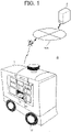
- Fig. 1 is a diagram illustrating a schematic configuration example of the monitoring system S according to the one or more embodiments.
- the monitoring system S includes an UGV (Unmanned Ground Vehicle) 1 and a management server 2.
- the UGV 1 and the management server 2 are operated by a delivery company or the like.
- the UGV 1 and the management server 2 are connectable to a communication network NW and are communicable with each other via the communication network NW.
- the communication network NW is configured from, for example, the Internet and a mobile communication network and a radio base station thereof.
- the UGV 1 illustrated in Fig. 1 indicates a vehicle including a plurality of wheels W
- the UGV 1 may be a travel body such as a robot (for example, a biped walking robot) including no wheels.
- the UGV 1 is an example of an unmanned ground vehicle capable of autonomously traveling in an unmanned manner.
- the UGV 1 delivers an article stored in a storage B (also referred to as storage box) to a delivery destination.
- the article can also be referred to as load or cargo.
- the article may be, for example, a commodity (an ordered product) ordered in an EC (Electronic Commerce) site.
- the delivery destination of the article may be, for example, a specific place having a doorway for a receiver (an example of a first person) of the article to enter and exit (that is, a person to appear.). Examples of such specific place include a house (a detached house or one room of an apartment), an office, a hotel room, and a cottage in a resort.
- the delivery destination of the article may be a simple tent installed in a specific place such as a camp site or a park, or a vehicle stopped in the specific place.
- the management server 2 manages information concerning delivery of the article and monitors a monitoring area at the delivery destination in cooperation with the UGV 1 in order to detect a person (hereinafter referred to as "outsider (third person) other than the receiver of the article.
- the outsider an example of a second person different from the first person
- the outsider includes a suspicious person intruding from a doorway (for example, an entrance of a house) in the specific place explained above and a suspicious person who is highly likely to intrude from the doorway.
- Fig. 2 is a diagram illustrating a schematic configuration example of the UGV 1.
- the UGV 1 includes a drive unit 11, a positioning unit 12, a communication unit 13, an imaging unit 14 (an example of an imaging device), an operation/display unit 15, a sound output unit 16, a storing unit 17, and a control unit 18.
- the UGV 1 includes a battery (not illustrated) that supplies power to the units of the UGV 1, wheels W, and a storage B.
- a battery not illustrated
- the UGV 1 may include a light L (for example, an LED) for notifying with light the receiver of the article of outsider detection information indicating that the outsider is detected (an example of information concerning detection of the outsider).
- a light L for example, an LED
- the receiver of the article of outsider detection information indicating that the outsider is detected (an example of information concerning detection of the outsider).
- a plurality of storages B are provided, a door Do of the storage B at the lowermost stage in the center is opened, and an article C can be taken out.
- the drive unit 11 includes a motor and a rotating shaft.
- the drive unit 11 rotates a plurality of wheels W with a motor, a rotating shaft, and the like driven according to a control signal output from the control unit 18.
- the positioning unit 12 includes a radio wave receiver.
- the positioning unit 12 receives, for example, a radio wave transmitted from a GNSS (Global Navigation Satellite System) satellite with a radio receiver and detects the current position (latitude and longitude) of the UGV 1 on the basis of the radio wave.
- the current position of the UGV 1 may be identified by SLAM (Simultaneous Localization And Mapping) processing in addition to the radio wave transmitted from the GNSS satellite.
- the current position of the UGV 1 may be corrected based on images captured (imaged) by the imaging unit 14.
- Position information indicating the current position detected by the positioning unit 12 is output to the control unit 18.
- the communication unit 13 performs control of communication performed via the communication network NW. Moreover, the communication unit 13 may have a short-range wireless communication function such as Bluetooth (registered trademark) and perform short-range wireless communication with a terminal (for example, a smartphone) of the receiver.
- the imaging unit 14 includes, for example, a wide-angle camera such as an omnidirectional camera. The wide-angle camera is used for traveling control of the UGV 1 and monitoring at a delivery destination of the article. For example, the imaging unit 14 continuously captures a real space in an imaging area (imaging range) that falls within the angle of view of the wide-angle camera. A moving image (moving image data) of the imaging area captured by the imaging is output to the control unit 18.
- the moving image of the imaging area captured at the delivery destination of the article is used to detect the receiver of the article and the outsider.
- the imaging unit 14 may include a camera used for traveling control of the UGV 1 and a camera used for monitoring at the delivery destination of the article.
- the operation/display unit 15 includes a display (touch panel) Di having an input function for receiving operation of a user such as the receiver and a display function for displaying information. For example, when the receiver inputs an unlocking code from the display Di, the door Do of the storage B is unlocked and opened. Alternatively, when near field wireless communication is performed between the UGV 1 and the terminal of the receiver, when the unlocking code is input from the terminal by the receiver through the application installed in the terminal and received by the communication unit 13, the door Do of the storage B is unlocked and opened. Moreover, the operation/display unit 15 is desirably used to notify the receiver of the article of outsider detection information with one or more images.
- the sound output unit 16 includes a speaker that outputs sound.
- the sound output unit 16 is desirably used to notify the receiver of the article of the outsider detection information with sound.
- the storing unit 17 is configured from a nonvolatile memory or the like and stores various programs and data.
- the storing unit 17 stores a machine body ID for identifying the UGV 1.
- the storing unit 17 is capable of recording a moving image of an imaging area captured in each of a plurality of different delivery destinations. However, after an article is received by a receiver at one delivery destination, the moving image may be deleted from the storing unit 17 (a memory) when the UGV 1 heads for the next delivery destination. This makes it possible to protect the privacy of the receiver of the article.
- the control unit 18 includes a CPU (Central Processing Unit), a ROM (Read Only Memory), and a RAM (Random Access Memory) and executes various kinds of processing according to a program stored in the ROM (or the storing unit 17).
- Fig. 3 is a diagram illustrating an example of functional blocks in the control unit 18. As illustrated in Fig. 3 , the control unit 18 functions as a traveling control unit 181, a moving image acquiring unit 182 (an example of an acquiring unit), a first detecting unit 183, a monitoring area setting unit 184 (an example of a first setting unit), a second detecting unit 185, a notification processing unit 186, and the like.
- the traveling control unit 181 performs traveling control for causing the UGV 1 to travel to the delivery destination of the article.
- control of the number of rotations of the wheels W and control of the position and a traveling direction of the UGV 1 are performed using position information acquired from the positioning unit 12, a moving image acquired from the imaging unit 14, delivery destination information of the article, and the like. Consequently, the UGV 1 can autonomously travel to the delivery destination.
- the delivery destination information of the article may be set in the UGV 1 at, for example, a shipping base of the article (in other words, an article loading base) or may be transmitted from the management server 2.
- the delivery destination information includes an article ID for identifying the article, location information of the delivery destination of the article, and receiver information of the article while being distinguished for each article.
- the location information of the delivery destination may be an address of the delivery destination or position information (latitude and longitude) of the delivery destination.
- the receiver information includes a user ID, a name, and an e-mail address for identifying the receiver of the article.
- the receiver information of the article may include a face image (photographic image data) of the receiver registered in advance.
- the moving image acquiring unit 182 acquires a moving image captured by the imaging unit 14.
- Such moving image is configured from a plurality of frame images.
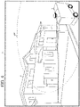
- Fig. 4 is a diagram illustrating an example of an imaging area AR1 captured by the UGV 1 that arrives at a delivery destination D of the article in the frame image F1.
- a frame image F1 illustrated in Fig. 4 a house D among a plurality of houses standing side by side is the delivery destination of the article and a doorway E of the house D is included in the imaging area AR1.
- control unit 18 may function as a second setting unit, detect, on the basis of frame images forming a moving image around the delivery destination of the article, a doorway present at the delivery destination, and set a range including the detected doorway as an imaging area.
- a range that falls within the angle of view of the omnidirectional camera when the UGV 1 arrives at the delivery destination may be set as the imaging area.
- the first detecting unit 183 executes, on the basis of one or more frame images forming the moving image acquired by the moving image acquiring unit 182, processing for detecting the receiver of the article.
- the receiver of the article can be detected by analyzing the frame images.
- the first detecting unit 183 desirably detects a doorway of the delivery destination (for example, a house or a vehicle) from the frame images and detects a person exiting from the detected doorway (that is, an appearing person) as the receiver of the article.
- the detected doorway and the person exiting from the doorway are stored in association with each other.
- the first detecting unit 183 may detect the site of the delivery destination (for example, a house) from the frame images and detect the person coming out of the detected site as the receiver of the article.
- the site of the delivery destination for example, a house
- a gate set in a boundary between the site and the outside of the site may be detected. In this case, a person coming out of the detected gate is detected as the receiver of the article.
- the first detecting unit 183 may detect a person appearing (showing up) in the frame images and moving toward the UGV 1 as the receiver of the article.
- the first detecting unit 183 may detect a person appearing in the frame images and is performing a motion of receiving the article as the receiver of the article.
- examples of the motion of receiving the article include a motion of taking out the article from the storage B and a motion of inputting an unlocking code to the UGV 1.
- the motion of inputting the unlocking code to the UGV 1 may be a motion of inputting the unlocking code from the display Di or a motion of inputting the unlocking code from a terminal of the receiver.
- the first detecting unit 183 may detect the receiver of the article using the face image registered in advance. In this case, the first detecting unit 183 collates a face of a person in the frame images with the face image registered in advance and detects the person in the frame images as the receiver of the article if a matching degree is equal to or greater than a threshold.
- the receiver to be identified can be accurately detected by any one of the first to fifth detecting methods.
- the receiver of the article may be detected by a combination of any two or more of the first to fifth detecting methods.
- the first detecting unit 183 detects and tracks a person coming out from the doorway (or the site) detected as explained above and identifies the person as the receiver of the article if the tracked person is heading for the UGV 1.
- the first detecting unit 183 may detect and track a person coming out of the detected doorway (or the site) as explained above, and identify the person as the receiver of the article if the tracked person is performing an operation of receiving the article.
- the first detecting unit 183 may detect a person coming out from the doorway (or the site) detected as explained above and identify the detected person as the receiver of the article if a matching degree of a face of the detected person and a face image registered in advance is equal to or greater than a threshold.
- the monitoring area setting unit 184 sets, as a monitoring area, an area including at least a part (for example, the upper body of the receiver) of the receiver detected by the first detecting unit 183 and the area at the point in time when the receiver appears, the area being narrower than the imaging area (for example, an area around the doorway where the receiver appears.).
- the area at the point in time when the receiver appears is an area in a first frame image representing at least a part of the receiver and is the area fixed also in a frame image temporally after the first frame image (that is, an area where a position does not change according to the movement of the receiver.). In this way, by narrowing the monitoring area to an appropriate range from the imaging area, it is possible to prevent unnecessary detection such as detection of a passer-by passing near the UGV 1 as much as possible.
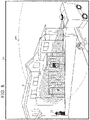
- Fig. 5 is a diagram illustrating an example of the imaging area AR1 and a monitoring area AR2 in a frame image F2.
- Fig. 6 is a diagram illustrating an example of the imaging area AR1 and the monitoring area AR2 in a frame image F3 temporally after the frame image F2 illustrated in Fig. 5 .
- the monitoring area AR2 at a point in time when a receiver P1 of an article comes out from the doorway E is set in the imaging area AR1.
- the monitoring area AR2 is set in the same position as illustrated in Fig. 6 also in the frame image F3 temporally after the frame image F2.
- a suspicious person P2 and a passer-by P3 appear but do not enter the monitoring area AR2.
- the second detecting unit 185 executes, on the basis of a frame image temporally later than the first frame image F2 (i.e., a frame image temporally after the first frame image F2) at a point in time the receiver detected by the first detecting unit 183 appears, processing for detecting the outsider entering the monitoring area AR2 or the outsider heading for the monitoring area AR2. Consequently, even when the monitoring area changes depending on an appearance position of the receiver of the article, the outsider can be appropriately detected.
- the outsider can be detected by analyzing the frame images. However, such outsider is not always a suspicious person and is sometimes a family member or an acquaintance of the receiver of the article. Fig.
- FIG. 7 is a diagram illustrating an example of the imaging area AR1 and the monitoring area AR2 in a frame image F4 temporally after the frame image F3 illustrated in Fig. 6 .
- the suspicious person P2 entering the monitoring range AR2 is detected.
- the suspicious person P2 may also be detected when the suspicious person P2 does not enter the monitoring range AR2 but is moving in the direction of the monitoring range AR2 and the distance to the monitoring area AR2 is equal to or smaller than a predetermined distance.
- the second detecting unit 185 may detect a person that is about to enter the doorway in the monitoring area AR2 or a person that has entered the doorway as the outsider. Consequently, the outsider to be identified can be accurately detected.
- the person about to enter the doorway is desirably detected on condition that, for example, the person is moving in the direction of the doorway and the distance to the doorway is equal to or smaller than a predetermined distance.
- the person about to enter the doorway may be detected on condition that the person has opened a door set in the doorway. Incidentally, when the person opening the door set in the doorway is a person exiting from the doorway, the person is desirably not detected as the outsider.
- the second detecting unit 185 may detect a person about to enter the site in the monitoring area AR2 or a person that has entered the site as the outsider.
- the person about to enter the site is desirably detected on condition that, for example, the person is moving from the outside of the site in the site and the distance to the site (that is, the distance between the person and the site) is equal to or smaller than a predetermined distance.
- the person about to enter the site may be detected on condition that the person has opened a gate set in the boundary between the site and the outside of the site. Incidentally, when the person opening the gate set in the boundary between the site and the outside of the site is a person coming out from the site, the person is desirably not detected as the outsider.
- the second detecting unit 185 may detect the outsider on the basis of a comparison result of the size of the receiver in the first frame image F2 at a point in time when the receiver detected by the first detecting unit 183 appears and the size of a person (a person other than the receiver) appearing in a frame image that is temporally later than the frame image F2. Consequently, the outsider to be identified can be more accurately detected.
- the second detecting unit 185 detects the person appearing in the frame image temporally after the frame image F2 as the outsider.
- the reason of determining whether the sizes are similar sizes is to detect the outsider present near a position where the receiver appears (for example, the doorway). For example, in Fig. 5 , the receiver P1 and the suspicious person P2 have similar sizes, but the receiver P1 and the passer-by P3 do not have similar sizes. Therefore, even if the passer-by P3 enters the monitoring area AR2, the passer-by P3 is not detected as the outsider. In this case, for example, it can be determined that the passer-by P3 is crossing the UGV 1.
- the notification processing unit 186 executes processing for notifying the receiver detected by the first detecting unit 183 of outsider detection information. Consequently, it is possible to more quickly alert the receiver of the article. For example, the notification processing unit 186 notifies the receiver of the article of the outsider detection information with light by lighting or flashing the light. Alternatively, the control unit 18 may notify of the outsider detection information with sound by causing a speaker of the sound output unit 16 to output an alarm (that is, amplifying sound from the speaker). Alternatively, the notification processing unit 186 may cause the communication unit 13 to transmit an e-mail indicating the outsider detection information to the e-mail address of the receiver of the article.
- the notification processing unit 186 may cause the communication unit 13 to transmit the outsider detection information to an application resident in the terminal of the receiver of the article. Incidentally, even when the outsider detected by the second detecting unit 185 is not a suspicious person, it is meaningful to attract attention by notifying the receiver of the article of the outsider detection information.
- the notification processing unit 186 may notify of the outsider detection information by causing the display Di of the operation/display unit 15 to display one or more images (a video) showing the outsider.
- the notification processing unit 186 may notify of the outsider detection information with one or more images through the near field wireless communication and an application installed in the terminal by causing a display of the terminal to display one or more showing the outsider.
- the notification processing unit 186 may cause the display Di or the display of the terminal to display a confirmation button for confirming with the receiver whether the outsider in the image displayed as explained above is a suspicious person.
- the notification processing unit 186 recognizes that the outsider shown in the displayed image is suspicious person and executes predetermined alarm processing.
- the alarm processing include processing for notifying the receiver not to return home with voice or display, processing for providing one or images showing a suspicious person to police, and processing for requesting another UGV to monitor the vicinity of the delivery destination.
- Fig. 8 is a diagram illustrating a schematic configuration example of the management server 2.
- the management server 2 includes a communication unit 21, a storing unit 22, and a control unit 23.
- the communication unit 21 performs control of communication performed via the communication network NW.
- the storing unit 22 is configured from, for example, a hard disk drive and stores various programs and data. For example, an article database (DB) 221 and the like are constructed in the storing unit 22.
- DB article database
- an article ID of an article, location information of a delivery destination of the article, receiver information of the article, an arrival time period of the article, a release code, a machine body ID of the UGV 1 that delivers the article, and the like are stored in association with one another for each article.
- the location information of the delivery destination of the article, the receiver information, and the arrival time period are stored in the article database 221, for example, when a delivery requester or the receiver accesses a predetermined site from a terminal and performs a delivery request procedure.
- the release code is a code necessary for unlocking the door Do of the storage B storing the article.
- the control unit 23 includes a CPU, a ROM, and a RAM and executes various kinds of processing according to a program stored in the ROM (or the storing unit 22). For example, the control unit 23 causes the communication unit 13 to transmit the delivery destination information to the UGV 1.
- Fig. 9 is a flowchart illustrating an example of processing executed by the control unit 18 of the UGV 1.
- the delivery destination information includes an article ID of the article, location information of a delivery destination of the article, and receiver information of the article.
- the delivery destination information may be transferred from the management server 2 to the UGV 1.
- the processing illustrated in Fig. 9 is started, for example, when the UGV 1 arrives at the delivery destination of the article. Incidentally, immediately before or when the UGV 1 arrives at the delivery destination of the article, the e-mail indicating that the UGV 1 has arrived may be transmitted to the e-mail address of the receiver of the article.
- the control unit 18 stops, on the basis of the location information of the delivery destination of the article, the UGV 1 in a position where a delivery destination direction can be confirmed (step S1).
- control unit 18 causes the imaging unit 14 to perform capturing (imaging) in the delivery destination direction in a wide range from the stop position of the UGV 1, starts acquisition of a moving image of the imaging area, and records the moving image in the storing unit 17 (step S2).
- step S4 determines whether the receiver of the article is detected.
- step S4: YES the processing proceeds to step S5.
- step S4: NO the processing returns to step S3.
- a predetermined time for example, about several ten minutes
- step S5 the control unit 18 sets, as the monitoring area, an area around an appearance position of the receiver (for example, the doorway of the house) detected in step S4 and the area at a point in time when the receiver appears.
- the control unit 18 monitors, on the basis of the frame image that is temporally later than the first frame image at the point in time when the receiver appears, the monitoring area set in step S5 (step S6). In such monitoring, processing for tracking the receiver of the article and processing for detecting the outsider other than the receiver are executed.
- step S7 determines whether the receiver to be tracked has received the article from the UGV 1 and returned to the appearance position (for example, has returned home) (step S7). If it is determined that the receiver to be tracked has not received the article from the UGV 1 or that the receiver has received the article from the UGV 1 but has not returned (step S7: NO), the processing proceeds to step S8. On the other hand, when it is determined that the receiver has received the article from the UGV 1 and has returned to the appearance position (step S7: YES), the monitoring is ended (step S10), and the processing proceeds to step S11.
- step S8 the control unit 18 determines whether the outsider entering the monitoring area set in step S5 or heading for the monitoring area is detected. when it is determined that the outsider is detected (step S8: YES), the processing proceeds to step S9. On the other hand, when it is determined that the outsider is not detected (step S8: NO), the processing returns to step S6.
- the control unit 18 may collate a face photograph of a person registered in advance on the basis of suspicious person information (for example, a wanted criminal) with a face of the detected outsider. Then, when a matching degree of the face photograph and the face of the outsider is equal to or greater than a threshold, it is determined that the outsider is a suspicious person performing a suspicious act, and the alarm processing explained above is desirably executed. On the other hand, when the matching degree of the face photograph and the face of the outsider is not equal to or greater than the threshold, the processing desirably proceeds to step S9.
- suspicious person information for example, a wanted criminal
- control unit 18 may collate a face photograph of a person registered in advance as a person notification of which is not to be provided (for example, a family member or an acquaintance of the receiver of the package) with a face of the detected outsider. Then, when a matching degree of the face photograph and the face of the outsider is equal to or greater than a threshold, it is determined that the outsider is a person notification of which is not to be provided, and the processing desirably returns to step S6.
- step S9 the control unit 18 executes notification processing of outsider detection information.
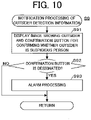
- Fig. 10 is a flowchart illustrating details of the notification processing illustrated in step S9.
- the control unit 18 causes, for example, the display Di to display one or more images showing the outsider detected in step S8 among frame images forming an acquired moving image and a confirmation button for confirming whether the outsider is a suspicious person (step S91).
- the images showing the outsider may be a moving image (that is, moving image reproduction).
- control unit 18 determines whether the displayed confirmation button is designated by the receiver within a predetermined time (step S92). When it is determined that the displayed confirmation button is not designated by the receiver within the predetermined time (step S92: NO), the processing returns to the processing illustrated in Fig. 9 . In this case, in the subsequent processing, the outsider shown in the one or more images is desirably set as a person not to be detected.
- step S92 when it is determined that the displayed confirmation button is designated by the receiver within the predetermined time (step S92: YES), the alarm processing explained above is executed (step S93), and the processing returns to step S6.
- notification of outsider detection information may be provided with light by lighting or flashing a light or the notification of the outsider detection information may be provided with sound by causing the speaker of the sound output unit 16 to output an alarm instead of the processing illustrated in Fig. 10 or together with the processing illustrated in Fig. 10 .
- step S11 the control unit 18 erases the moving image started to be acquired in step S2 and recorded in the storing unit 17.
- the control unit 18 moves the UGV 1 toward a delivery destination of a next article (step S12). Thereafter, the processing illustrated in Fig. 9 ends once and is started again when the UGV 1 arrives at the delivery destination of the next article.
- the moving image of the imaging area captured by the UGV 1 is acquired, the receiver of the article is detected based on the frame images forming the moving image, the area including at least a part of the receiver and the area at the point in time when the receiver appears is set as the monitoring area, the outsider entering the monitoring area or heading for the monitoring area is detected based on the frame image that is temporally later than the first frame image at the point in time when the receiver appears, and the receiver is notified of the outsider detection information. Therefore, even when the monitoring area changes depending on an appearance position of the receiver of the article, security risks such as intrusion into a house or the like can be avoided.
- the UGV 1 since the UGV 1 includes the imaging unit 14 and is configured to acquire a moving image of an imaging area captured by the imaging unit 14, even when an imaging device such as a monitoring camera is not set in a specific place such as a delivery destination of an article, security risks such as intrusion into a house or the like can be avoided, and the UGV 1 can be effectively utilized compared with the related art.
- the above-described embodiment is one embodiment of the present invention, and the present invention is not limited to the above-described embodiment, changes from the above-described embodiment can be made on various configurations and the like within a scope not departing from the gist of the present invention, and such cases shall be also included in the technical scope of the present invention.
- the embodiment explained above can also be applied, for example, when a person appears from behind (for example, from the back of) an object such as a building (that is, appears from a place other than a doorway,).
- the embodiment explained above can also be applied when a commodity is sold to the receiver in the UGV 1 also serving as a vending machine at a delivery destination.
- the UGV 1 detects, on the basis of frame images forming a moving image of an imaged imaging area, a person purchasing an article from the UGV 1 with the detecting method explained above as the first person. Then, the UGV 1 sets an area including at least a part of the person purchasing the article and the area at a point in time when the person purchasing the article appears, the area being narrower than the imaging area, as the monitoring area, detects the outsider in the same manner as in the embodiment explained above, and notifies the person purchasing the article of outsider detection information.
- the embodiment explained above can also be applied when the UGV 1 receives an article from a person in a specific place other than a delivery destination.
- the UGV 1 detects, on the basis of frame images forming a moving image of an captured imaging area, a person passing an article to the UGV 1 (for example, a person depositing an article) with the detecting method explained above as the first person. Then, the UGV 1 sets an area including at least a part of the person passing the article and the area at a point in time when the person delivering the article appears, the area being narrower than the imaging area, as the monitoring area, detects the outsider in the same manner as in the embodiment explained above, and notifies the person passing the article of outsider detection information.
- the embodiment explained above can also be applied to a case other than exchange of an article by the UGV 1.
- the UGV 1 communicates predetermined information to a person.
- the UGV 1 detects, on the basis of frame images forming a moving image of an captured imaging area, a person receiving information from the UGV 1 (for example, receiving information through sound output or display output) with the detecting method explained above as the first person.
- the UGV 1 sets an area including at least a part of the person receiving the information and the area at a point in time when the person receiving the information appears, the area being narrower than the imaging area, as the monitoring area, detects the outsider in the same manner as in the embodiment explained above, and notifies the person receiving the information of the outsider detection information.
- the moving image acquiring unit 182 the first detecting unit 183, the monitoring area setting unit 184, the second detecting unit 185, and the notification processing unit 186 are provided in the control unit 18 of the UGV 1 is explained.
- all or a part of the functions of these components may be included in the control unit 23 of the management server 2.
- the UGV 1 transmits a moving image of an imaging area captured by the imaging unit 14 to the management server 2 via the communication network NW.
- the management server 2 acquires the moving image transmitted from the UGV 1 and detects a first person with the detecting method explained above on the basis of frame images forming the moving image.
- the management server 2 sets an area including at least a part of the first person and the area at a point in time when the first person appears, the area being narrower than the imaging area as a monitoring area and detects the outsider in the same manner as in the embodiment explained above. Then, the management server 2 notifies the detected first person of outsider detection information by e-mail. Alternatively, the management server 2 notifies the first person of the outsider detection information by transmitting the outsider detection information to the UGV 1 via the communication network NW.
- the management server 2 may acquire a moving image captured by an imaging device other than the imaging unit 14 of the UGV 1.
- an imaging device any monitoring camera among a plurality of monitoring cameras set in a specific area and connected to the communication network NW can be used.
- the management server 2 executes processing for acquiring a moving image transmitted from the monitoring camera, detecting a first person on the basis of frame images forming the moving image and setting the first person as the monitoring area, detecting the outsider as explained above, and notifying the first person of outsider detection information.
Landscapes
- Engineering & Computer Science (AREA)
- Physics & Mathematics (AREA)
- General Physics & Mathematics (AREA)
- Multimedia (AREA)
- Theoretical Computer Science (AREA)
- Computer Vision & Pattern Recognition (AREA)
- Health & Medical Sciences (AREA)
- General Health & Medical Sciences (AREA)
- Human Computer Interaction (AREA)
- Remote Sensing (AREA)
- Aviation & Aerospace Engineering (AREA)
- Radar, Positioning & Navigation (AREA)
- Automation & Control Theory (AREA)
- Psychiatry (AREA)
- Social Psychology (AREA)
- Electromagnetism (AREA)
- Oral & Maxillofacial Surgery (AREA)
- Alarm Systems (AREA)
- Closed-Circuit Television Systems (AREA)
- Burglar Alarm Systems (AREA)
- Emergency Alarm Devices (AREA)
- Traffic Control Systems (AREA)
Abstract
Description
- The present invention relates to a technical field such as a monitoring system that monitors intrusion using an imaging device.
- Conventionally, a monitoring system that monitors intrusion into a house or the like is known. For example,
Patent Literature 1 discloses a monitoring system configured such that, when an intruder is detected by a sensor that detects an intruder into a monitoring area such as an entrance, an email is transmitted to a monitoring side and an image captured by a camera installed in the monitoring area is transferred to the monitoring side at predetermined timing via a wireless network. On the other hand, it has been studied that an unmanned vehicle delivers an article to any place such as a house. For example,Patent Literature 2 discloses a delivery system in which an unmanned vehicle delivers an article to any place such as a house and a receiver directly receives the article from the unmanned vehicle. -
- Patent Literature 1:
JP 2004-21604 A - Patent Literature 2:
JP 2020-7148 A - However, in the delivery system as disclosed in
Patent Literature 2, for example, when the receiver coming out of the house or the like receives the article from the unmanned vehicle outdoors, there is a high possibility that the receiver turns his/her back to the house or the like. Therefore, there is a security risk such as intrusion into the house or the like by a suspicious person. In order to avoid such a security risk, for example, even if the monitoring system disclosed inPatent Literature 1 is used, it is difficult to avoid the security risk explained above because the area where the receiver comes out can change (that is, the monitoring area can change depending on an appearance position or the like of the receiver.). The same applies, for example, when the person coming from the house or the like passes an article to the unmanned vehicle or the like outdoors. - Therefore, one or more embodiments of the present invention are directed to providing a monitoring system and an unmanned vehicle capable of avoiding a security risk such as intrusion into a house or the like even when a monitoring area changes depending on an appearance position or the like of a person.
- In response to the above issue, the invention according to
claim 1 is a monitoring system that monitors a monitoring area using an imaging device. The monitoring system includes: an acquiring unit configured to acquire a moving image of an imaging area imaged by the imaging device; a first detecting unit configured to detect a first person on a basis of frame images forming the moving image; a first setting unit configured to set, as the monitoring area, an area including at least a part of the first person and the area at a point in time when the first person appears, the area being narrower than the imaging area; a second detecting unit configured to detect a second person entering the monitoring area or a second person heading for the monitoring area, the second person being a person different from the first person, on a basis of a frame image that is temporally later than a first frame image at the point in time when the first person appears; and a notification processing unit configured to execute processing for notifying the first person of information concerning the detection of the second person. Consequently, even when a monitoring area changes depending on an appearance position or the like of a person, it is possible to avoid a security risk such as intrusion into a house or the like. - The invention according to
claim 2 is the monitoring system according toclaim 1 further including an unmanned ground vehicle including the imaging device and the acquiring unit. Consequently, even when an imaging device such as a monitoring camera is not installed in a specific place such as a delivery destination of an article, it is possible to avoid a security risk such as intrusion into a house or the like. - The invention according to claim 3 is the monitoring system according to
claim 2, wherein the unmanned ground vehicle is a ground vehicle that delivers an article to each of a plurality of different delivery destinations in an unmanned manner. The unmanned ground vehicle records the moving image acquired by the acquiring unit at one delivery destination in a memory and erases the moving image from the memory when heading to a next delivery destination after the article is received by the first person at the one delivery destination. This makes it possible to protect the privacy of a first person. - The invention according to claim 4 is the monitoring system according to
claim 2 or 3, wherein the first detecting unit detects a person moving toward the unmanned ground vehicle as the first person. This makes it possible to accurately detect the first person to be identified. - The invention according to claim 5 is the monitoring system according to any one of
claims 1 to 4 further including a second setting unit configured to detect a doorway on a basis of frame images forming the moving image and to set a range including the detected doorway as the imaging area. - The invention according to
claim 6 is the monitoring system according to claim 5, wherein the first detecting unit detects a person exiting from the doorway as the first person. This makes it possible to accurately detect the first person to be identified. - The invention according to claim 7 is the monitoring system according to
claim 5 or 6, wherein the second detecting unit detects, as the second person, a person that is about to enter the doorway or a person that has entered the doorway, the second person being different from the first person. This makes it possible to accurately detect the second person to be identified. - The invention according to
claim 8 is the monitoring system according to any one ofclaims 1 to 7, wherein the first detecting unit detects a person performing a motion of receiving an article as the first person. This makes it possible to accurately detect the first person to be identified. - The invention according to claim 9 is the monitoring system according to any one of
claims 1 to 8, wherein the first detecting unit detects a person coming out of a site as the first person. This makes it possible to accurately detect the first person to be identified. - The invention according to claim 10 is the monitoring system according to any one of
claims 1 to 9, wherein the second detecting unit detects, as the second person, a person that is about to enter a site or a person that has entered the site, the second person being different from the first person. This makes it possible to accurately detect the second person to be identified. - The invention according to
claim 11 is the monitoring system according to any one ofclaims 1 to 10, wherein the first detecting unit detects the first person using a face image registered in advance. This makes it possible to more accurately detect the first person to be identified. - The invention according to
claim 12 is the monitoring system according to any one ofclaims 1 to 11, wherein the second detecting unit detects the second person on a basis of a comparison result of a size of the first person in the first frame image at a point in time when the first person appears and a size of a person appearing in the frame image that is temporally later than the first frame image, the person appearing being different from the first person. This makes it possible to more accurately detect the second person to be identified. - The invention according to
claim 13 is the monitoring system according to any one ofclaims 1 to 12, wherein the notification processing unit executes processing for notifying with light of information concerning detection of the second person. This makes it possible to more quickly alert the first person. - The invention according to
claim 14 is the monitoring system according to any one ofclaims 1 to 13, wherein the notification processing unit executes processing for notifying with sound of information concerning detection of the second person. This makes it possible to more quickly alert the first person. - The invention according to
claim 15 is the monitoring system according to any one ofclaims 1 to 14, wherein the notification processing unit executes processing for notifying with one or more images of information concerning detection of the second person. This makes it possible to more quickly alert the first person. - The invention according to
claim 16 is an unmanned vehicle that monitors a monitoring area using an imaging device. The unmanned vehicle includes: an acquiring unit configured to acquire a moving image of an imaging area imaged by the imaging device; a first detecting unit configured to detect a first person on a basis of frame images forming the moving image; a first setting unit configured to set, as the monitoring area, an area including at least a part of the first person and the area at a point in time when the first person appears, the area being narrower than the imaging area; a second detecting unit configured to detect a second person entering the monitoring area or a second person heading for the monitoring area, the second person being a person different from the first person, on a basis of a frame image that is temporally later than a first frame image at the point in time when the first person appears; and a notification processing unit configured to execute processing for notifying the first person of information concerning detection of the second person. - According to one or more embodiments of the present invention, even when a monitoring area changes depending on an appearance position or the like of a person, it is possible to avoid a security risk such as intrusion into a house or the like.
-
-
FIG. 1 is a diagram illustrating a schematic configuration example of a monitoring system S according to one or more embodiments. -
FIG. 2 is a diagram illustrating a schematic configuration example of anUGV 1. -
FIG. 3 is a diagram illustrating an example of functional blocks in acontrol unit 18. -
FIG. 4 is a diagram illustrating an example of an imaging area AR1 captured by theUGV 1 that arrives at a delivery destination D of an article in a frame image F1. -
FIG. 5 is a diagram illustrating an example of the imaging area AR1 and a monitoring area AR2 in a frame image F2. -
FIG. 6 is a diagram illustrating an example of the imaging area AR1 and the monitoring area AR2 in a frame image F3 temporally after the frame image F2 illustrated inFig. 5 . -
FIG. 7 is a diagram illustrating an example of the imaging area AR1 and the monitoring area AR2 in a frame image F4 temporally after the frame image F3 illustrated inFig. 6 . -
FIG. 8 is a diagram illustrating a schematic configuration example of amanagement server 2. -
FIG. 9 is a flowchart illustrating an example of processing executed by thecontrol unit 18 of theUGV 1. -
FIG. 10 is a flowchart illustrating details of the notification processing illustrated in step S9. - one or more embodiments of the present invention is explained below with reference to the drawings. Incidentally, the embodiments explained below is embodiments in the case where a monitoring system (surveillance system) that monitors a monitoring area (surveillance area) using an imaging device is applied to delivery (transportation) of an article.
- First, a configuration and function outline of a monitoring system S according to the one or more embodiments is explained with reference to
Fig. 1. Fig. 1 is a diagram illustrating a schematic configuration example of the monitoring system S according to the one or more embodiments. As illustrated inFig. 1 , the monitoring system S includes an UGV (Unmanned Ground Vehicle) 1 and amanagement server 2. TheUGV 1 and themanagement server 2 are operated by a delivery company or the like. TheUGV 1 and themanagement server 2 are connectable to a communication network NW and are communicable with each other via the communication network NW. The communication network NW is configured from, for example, the Internet and a mobile communication network and a radio base station thereof. Incidentally, although theUGV 1 illustrated inFig. 1 indicates a vehicle including a plurality of wheels W, theUGV 1 may be a travel body such as a robot (for example, a biped walking robot) including no wheels. - The
UGV 1 is an example of an unmanned ground vehicle capable of autonomously traveling in an unmanned manner. TheUGV 1 delivers an article stored in a storage B (also referred to as storage box) to a delivery destination. The article can also be referred to as load or cargo. The article may be, for example, a commodity (an ordered product) ordered in an EC (Electronic Commerce) site. The delivery destination of the article may be, for example, a specific place having a doorway for a receiver (an example of a first person) of the article to enter and exit (that is, a person to appear.). Examples of such specific place include a house (a detached house or one room of an apartment), an office, a hotel room, and a cottage in a resort. Alternatively, the delivery destination of the article may be a simple tent installed in a specific place such as a camp site or a park, or a vehicle stopped in the specific place. Themanagement server 2 manages information concerning delivery of the article and monitors a monitoring area at the delivery destination in cooperation with theUGV 1 in order to detect a person (hereinafter referred to as "outsider (third person) other than the receiver of the article. Here, the outsider (an example of a second person different from the first person) includes a suspicious person intruding from a doorway (for example, an entrance of a house) in the specific place explained above and a suspicious person who is highly likely to intrude from the doorway. - Next, a configuration and a function of the
UGV 1 are explained with reference toFig. 2. Fig. 2 is a diagram illustrating a schematic configuration example of theUGV 1. As illustrated inFig. 2 , theUGV 1 includes adrive unit 11, apositioning unit 12, acommunication unit 13, an imaging unit 14 (an example of an imaging device), an operation/display unit 15, asound output unit 16, a storingunit 17, and acontrol unit 18. Moreover, theUGV 1 includes a battery (not illustrated) that supplies power to the units of theUGV 1, wheels W, and a storage B. Furthermore, as illustrated inFig. 1 , theUGV 1 may include a light L (for example, an LED) for notifying with light the receiver of the article of outsider detection information indicating that the outsider is detected (an example of information concerning detection of the outsider). Incidentally, in the example illustrated inFig. 1 , a plurality of storages B are provided, a door Do of the storage B at the lowermost stage in the center is opened, and an article C can be taken out. - The
drive unit 11 includes a motor and a rotating shaft. Thedrive unit 11 rotates a plurality of wheels W with a motor, a rotating shaft, and the like driven according to a control signal output from thecontrol unit 18. Thepositioning unit 12 includes a radio wave receiver. Thepositioning unit 12 receives, for example, a radio wave transmitted from a GNSS (Global Navigation Satellite System) satellite with a radio receiver and detects the current position (latitude and longitude) of theUGV 1 on the basis of the radio wave. Incidentally, the current position of theUGV 1 may be identified by SLAM (Simultaneous Localization And Mapping) processing in addition to the radio wave transmitted from the GNSS satellite. The current position of theUGV 1 may be corrected based on images captured (imaged) by theimaging unit 14. Position information indicating the current position detected by thepositioning unit 12 is output to thecontrol unit 18. - The
communication unit 13 performs control of communication performed via the communication network NW. Moreover, thecommunication unit 13 may have a short-range wireless communication function such as Bluetooth (registered trademark) and perform short-range wireless communication with a terminal (for example, a smartphone) of the receiver. Theimaging unit 14 includes, for example, a wide-angle camera such as an omnidirectional camera. The wide-angle camera is used for traveling control of theUGV 1 and monitoring at a delivery destination of the article. For example, theimaging unit 14 continuously captures a real space in an imaging area (imaging range) that falls within the angle of view of the wide-angle camera. A moving image (moving image data) of the imaging area captured by the imaging is output to thecontrol unit 18. In particular, the moving image of the imaging area captured at the delivery destination of the article is used to detect the receiver of the article and the outsider. Incidentally, theimaging unit 14 may include a camera used for traveling control of theUGV 1 and a camera used for monitoring at the delivery destination of the article. - The operation/
display unit 15 includes a display (touch panel) Di having an input function for receiving operation of a user such as the receiver and a display function for displaying information. For example, when the receiver inputs an unlocking code from the display Di, the door Do of the storage B is unlocked and opened. Alternatively, when near field wireless communication is performed between theUGV 1 and the terminal of the receiver, when the unlocking code is input from the terminal by the receiver through the application installed in the terminal and received by thecommunication unit 13, the door Do of the storage B is unlocked and opened. Moreover, the operation/display unit 15 is desirably used to notify the receiver of the article of outsider detection information with one or more images. - The
sound output unit 16 includes a speaker that outputs sound. Thesound output unit 16 is desirably used to notify the receiver of the article of the outsider detection information with sound. Moreover, the storingunit 17 is configured from a nonvolatile memory or the like and stores various programs and data. The storingunit 17 stores a machine body ID for identifying theUGV 1. Furthermore, the storingunit 17 is capable of recording a moving image of an imaging area captured in each of a plurality of different delivery destinations. However, after an article is received by a receiver at one delivery destination, the moving image may be deleted from the storing unit 17 (a memory) when theUGV 1 heads for the next delivery destination. This makes it possible to protect the privacy of the receiver of the article. - The
control unit 18 includes a CPU (Central Processing Unit), a ROM (Read Only Memory), and a RAM (Random Access Memory) and executes various kinds of processing according to a program stored in the ROM (or the storing unit 17).Fig. 3 is a diagram illustrating an example of functional blocks in thecontrol unit 18. As illustrated inFig. 3 , thecontrol unit 18 functions as a travelingcontrol unit 181, a moving image acquiring unit 182 (an example of an acquiring unit), a first detectingunit 183, a monitoring area setting unit 184 (an example of a first setting unit), a second detectingunit 185, anotification processing unit 186, and the like. - The traveling
control unit 181 performs traveling control for causing theUGV 1 to travel to the delivery destination of the article. In this traveling control, control of the number of rotations of the wheels W and control of the position and a traveling direction of theUGV 1 are performed using position information acquired from thepositioning unit 12, a moving image acquired from theimaging unit 14, delivery destination information of the article, and the like. Consequently, theUGV 1 can autonomously travel to the delivery destination. Here, the delivery destination information of the article may be set in theUGV 1 at, for example, a shipping base of the article (in other words, an article loading base) or may be transmitted from themanagement server 2. The delivery destination information includes an article ID for identifying the article, location information of the delivery destination of the article, and receiver information of the article while being distinguished for each article. The location information of the delivery destination may be an address of the delivery destination or position information (latitude and longitude) of the delivery destination. The receiver information includes a user ID, a name, and an e-mail address for identifying the receiver of the article. Incidentally, the receiver information of the article may include a face image (photographic image data) of the receiver registered in advance. Moreover, when theUGV 1 arrives at the delivery destination of the article, the travelingcontrol unit 181 stops, on the basis of the location information of the delivery destination, theUGV 1 in a position where the direction of the delivery destination can be confirmed. - The moving
image acquiring unit 182 acquires a moving image captured by theimaging unit 14. Such moving image is configured from a plurality of frame images.Fig. 4 is a diagram illustrating an example of an imaging area AR1 captured by theUGV 1 that arrives at a delivery destination D of the article in the frame image F1. In a frame image F1 illustrated inFig. 4 , a house D among a plurality of houses standing side by side is the delivery destination of the article and a doorway E of the house D is included in the imaging area AR1. Incidentally, thecontrol unit 18 may function as a second setting unit, detect, on the basis of frame images forming a moving image around the delivery destination of the article, a doorway present at the delivery destination, and set a range including the detected doorway as an imaging area. However, when an omnidirectional camera capable of imaging a range of 360 degrees centering on theUGV 1 is used, even if an imaging area is not intentionally set, a range that falls within the angle of view of the omnidirectional camera when theUGV 1 arrives at the delivery destination may be set as the imaging area. - The first detecting
unit 183 executes, on the basis of one or more frame images forming the moving image acquired by the movingimage acquiring unit 182, processing for detecting the receiver of the article. Here, the receiver of the article can be detected by analyzing the frame images. As a first method of detecting the receiver, the first detectingunit 183 desirably detects a doorway of the delivery destination (for example, a house or a vehicle) from the frame images and detects a person exiting from the detected doorway (that is, an appearing person) as the receiver of the article. Incidentally, the detected doorway and the person exiting from the doorway are stored in association with each other. Alternatively, as a second method of detecting the receiver, the first detectingunit 183 may detect the site of the delivery destination (for example, a house) from the frame images and detect the person coming out of the detected site as the receiver of the article. Incidentally, instead of the detection of the site, a gate set in a boundary between the site and the outside of the site may be detected. In this case, a person coming out of the detected gate is detected as the receiver of the article. - Alternatively, as a third method of detecting the receiver, the first detecting
unit 183 may detect a person appearing (showing up) in the frame images and moving toward theUGV 1 as the receiver of the article. Alternatively, as a fourth method of detecting the receiver, the first detectingunit 183 may detect a person appearing in the frame images and is performing a motion of receiving the article as the receiver of the article. Here, examples of the motion of receiving the article include a motion of taking out the article from the storage B and a motion of inputting an unlocking code to theUGV 1. The motion of inputting the unlocking code to theUGV 1 may be a motion of inputting the unlocking code from the display Di or a motion of inputting the unlocking code from a terminal of the receiver. Alternatively, when a face image is registered in advance in association with the article ID of the article, as a fifth detecting method, the first detectingunit 183 may detect the receiver of the article using the face image registered in advance. In this case, the first detectingunit 183 collates a face of a person in the frame images with the face image registered in advance and detects the person in the frame images as the receiver of the article if a matching degree is equal to or greater than a threshold. - As explained above, the receiver to be identified can be accurately detected by any one of the first to fifth detecting methods. Furthermore, in order to further improve the accuracy of identifying the receiver of the article, the receiver of the article may be detected by a combination of any two or more of the first to fifth detecting methods. For example, the first detecting
unit 183 detects and tracks a person coming out from the doorway (or the site) detected as explained above and identifies the person as the receiver of the article if the tracked person is heading for theUGV 1. Alternatively, the first detectingunit 183 may detect and track a person coming out of the detected doorway (or the site) as explained above, and identify the person as the receiver of the article if the tracked person is performing an operation of receiving the article. Alternatively, the first detectingunit 183 may detect a person coming out from the doorway (or the site) detected as explained above and identify the detected person as the receiver of the article if a matching degree of a face of the detected person and a face image registered in advance is equal to or greater than a threshold. - The monitoring
area setting unit 184 sets, as a monitoring area, an area including at least a part (for example, the upper body of the receiver) of the receiver detected by the first detectingunit 183 and the area at the point in time when the receiver appears, the area being narrower than the imaging area (for example, an area around the doorway where the receiver appears.). Here, the area at the point in time when the receiver appears is an area in a first frame image representing at least a part of the receiver and is the area fixed also in a frame image temporally after the first frame image (that is, an area where a position does not change according to the movement of the receiver.). In this way, by narrowing the monitoring area to an appropriate range from the imaging area, it is possible to prevent unnecessary detection such as detection of a passer-by passing near theUGV 1 as much as possible. -
Fig. 5 is a diagram illustrating an example of the imaging area AR1 and a monitoring area AR2 in a frame image F2.Fig. 6 is a diagram illustrating an example of the imaging area AR1 and the monitoring area AR2 in a frame image F3 temporally after the frame image F2 illustrated inFig. 5 . In the frame image F2 illustrated inFig. 5 , the monitoring area AR2 at a point in time when a receiver P1 of an article comes out from the doorway E is set in the imaging area AR1. Then, the monitoring area AR2 is set in the same position as illustrated inFig. 6 also in the frame image F3 temporally after the frame image F2. The same applies to frame images temporally after the frame image F3. Incidentally, in the frame images F2 and F3 illustrated inFigs. 5 and6 , a suspicious person P2 and a passer-by P3 appear but do not enter the monitoring area AR2. - The second detecting
unit 185 executes, on the basis of a frame image temporally later than the first frame image F2 (i.e., a frame image temporally after the first frame image F2) at a point in time the receiver detected by the first detectingunit 183 appears, processing for detecting the outsider entering the monitoring area AR2 or the outsider heading for the monitoring area AR2. Consequently, even when the monitoring area changes depending on an appearance position of the receiver of the article, the outsider can be appropriately detected. Here, the outsider can be detected by analyzing the frame images. However, such outsider is not always a suspicious person and is sometimes a family member or an acquaintance of the receiver of the article.Fig. 7 is a diagram illustrating an example of the imaging area AR1 and the monitoring area AR2 in a frame image F4 temporally after the frame image F3 illustrated inFig. 6 . In the example illustratedFig. 7 , the suspicious person P2 entering the monitoring range AR2 is detected. Incidentally, the suspicious person P2 may also be detected when the suspicious person P2 does not enter the monitoring range AR2 but is moving in the direction of the monitoring range AR2 and the distance to the monitoring area AR2 is equal to or smaller than a predetermined distance. - As a more preferable example, the second detecting
unit 185 may detect a person that is about to enter the doorway in the monitoring area AR2 or a person that has entered the doorway as the outsider. Consequently, the outsider to be identified can be accurately detected. Here, the person about to enter the doorway is desirably detected on condition that, for example, the person is moving in the direction of the doorway and the distance to the doorway is equal to or smaller than a predetermined distance. Alternatively, the person about to enter the doorway may be detected on condition that the person has opened a door set in the doorway. Incidentally, when the person opening the door set in the doorway is a person exiting from the doorway, the person is desirably not detected as the outsider. Alternatively, the second detectingunit 185 may detect a person about to enter the site in the monitoring area AR2 or a person that has entered the site as the outsider. Here, the person about to enter the site is desirably detected on condition that, for example, the person is moving from the outside of the site in the site and the distance to the site (that is, the distance between the person and the site) is equal to or smaller than a predetermined distance. Alternatively, the person about to enter the site may be detected on condition that the person has opened a gate set in the boundary between the site and the outside of the site. Incidentally, when the person opening the gate set in the boundary between the site and the outside of the site is a person coming out from the site, the person is desirably not detected as the outsider. - As a more preferable example, the second detecting
unit 185 may detect the outsider on the basis of a comparison result of the size of the receiver in the first frame image F2 at a point in time when the receiver detected by the first detectingunit 183 appears and the size of a person (a person other than the receiver) appearing in a frame image that is temporally later than the frame image F2. Consequently, the outsider to be identified can be more accurately detected. For example, when the size of the receiver in the frame image F2 and the size of the person appearing in the frame image temporally after the frame image F2 are similar sizes (for example, when the difference between the sizes of the faces of the persons is equal to or smaller than a threshold), the second detectingunit 185 detects the person appearing in the frame image temporally after the frame image F2 as the outsider. Here, The reason of determining whether the sizes are similar sizes is to detect the outsider present near a position where the receiver appears (for example, the doorway). For example, inFig. 5 , the receiver P1 and the suspicious person P2 have similar sizes, but the receiver P1 and the passer-by P3 do not have similar sizes. Therefore, even if the passer-by P3 enters the monitoring area AR2, the passer-by P3 is not detected as the outsider. In this case, for example, it can be determined that the passer-by P3 is crossing theUGV 1. - The
notification processing unit 186 executes processing for notifying the receiver detected by the first detectingunit 183 of outsider detection information. Consequently, it is possible to more quickly alert the receiver of the article. For example, thenotification processing unit 186 notifies the receiver of the article of the outsider detection information with light by lighting or flashing the light. Alternatively, thecontrol unit 18 may notify of the outsider detection information with sound by causing a speaker of thesound output unit 16 to output an alarm (that is, amplifying sound from the speaker). Alternatively, thenotification processing unit 186 may cause thecommunication unit 13 to transmit an e-mail indicating the outsider detection information to the e-mail address of the receiver of the article. Alternatively, thenotification processing unit 186 may cause thecommunication unit 13 to transmit the outsider detection information to an application resident in the terminal of the receiver of the article. Incidentally, even when the outsider detected by the second detectingunit 185 is not a suspicious person, it is meaningful to attract attention by notifying the receiver of the article of the outsider detection information. - Alternatively, the
notification processing unit 186 may notify of the outsider detection information by causing the display Di of the operation/display unit 15 to display one or more images (a video) showing the outsider. Incidentally, when the near field wireless communication is performed between theUGV 1 and the terminal of the receiver, thenotification processing unit 186 may notify of the outsider detection information with one or more images through the near field wireless communication and an application installed in the terminal by causing a display of the terminal to display one or more showing the outsider. Moreover, thenotification processing unit 186 may cause the display Di or the display of the terminal to display a confirmation button for confirming with the receiver whether the outsider in the image displayed as explained above is a suspicious person. In this case, for example, when the confirmation button is designated (pressed) by the receiver, thenotification processing unit 186 recognizes that the outsider shown in the displayed image is suspicious person and executes predetermined alarm processing. Here, examples of the alarm processing include processing for notifying the receiver not to return home with voice or display, processing for providing one or images showing a suspicious person to police, and processing for requesting another UGV to monitor the vicinity of the delivery destination. - Next, a configuration and a function of the
management server 2 are explained with reference toFig. 8. Fig. 8 is a diagram illustrating a schematic configuration example of themanagement server 2. As illustrated inFig. 8 , themanagement server 2 includes acommunication unit 21, a storingunit 22, and acontrol unit 23. Thecommunication unit 21 performs control of communication performed via the communication network NW. The storingunit 22 is configured from, for example, a hard disk drive and stores various programs and data. For example, an article database (DB) 221 and the like are constructed in the storingunit 22. In thearticle database 221, an article ID of an article, location information of a delivery destination of the article, receiver information of the article, an arrival time period of the article, a release code, a machine body ID of theUGV 1 that delivers the article, and the like are stored in association with one another for each article. Here, the location information of the delivery destination of the article, the receiver information, and the arrival time period are stored in thearticle database 221, for example, when a delivery requester or the receiver accesses a predetermined site from a terminal and performs a delivery request procedure. The release code is a code necessary for unlocking the door Do of the storage B storing the article. For example, notification of the release code and the arrival time zone are provided in advance by e-mail to the e-mail address of the receiver of the article. Thecontrol unit 23 includes a CPU, a ROM, and a RAM and executes various kinds of processing according to a program stored in the ROM (or the storing unit 22). For example, thecontrol unit 23 causes thecommunication unit 13 to transmit the delivery destination information to theUGV 1. - Next, an operation of the monitoring system S according to the present embodiment is explained with reference to
Fig. 9 andFig. 10 .Fig. 9 is a flowchart illustrating an example of processing executed by thecontrol unit 18 of theUGV 1. In this operation example, it is assumed that delivery destination information of an article is set in theUGV 1 in a shipping base where the article is loaded into theUGV 1. The delivery destination information includes an article ID of the article, location information of a delivery destination of the article, and receiver information of the article. Incidentally, the delivery destination information may be transferred from themanagement server 2 to theUGV 1. - The processing illustrated in
Fig. 9 is started, for example, when theUGV 1 arrives at the delivery destination of the article. Incidentally, immediately before or when theUGV 1 arrives at the delivery destination of the article, the e-mail indicating that theUGV 1 has arrived may be transmitted to the e-mail address of the receiver of the article. When the processing illustrated inFig. 9 is started, thecontrol unit 18 stops, on the basis of the location information of the delivery destination of the article, theUGV 1 in a position where a delivery destination direction can be confirmed (step S1). Next, thecontrol unit 18 causes theimaging unit 14 to perform capturing (imaging) in the delivery destination direction in a wide range from the stop position of theUGV 1, starts acquisition of a moving image of the imaging area, and records the moving image in the storing unit 17 (step S2). - Next, the
control unit 18 executes, on the basis of frame images forming the acquired moving image, processing for detecting the receiver of the article as explained above (step S3). Next, thecontrol unit 18 determines whether the receiver of the article is detected (step S4). When it is determined that the receiver of the article is detected (step S4: YES), the processing proceeds to step S5. At this time, for example, since theUGV 1 is on standby in front of the receiver's home, it is assumed that the receiver of the article goes to theUGV 1 to pick up the article without closing a door of an entrance. On the other hand, when it is determined that the receiver of the article is not detected (step S4: NO), the processing returns to step S3. Incidentally, when it is determined that the receiver of the article is not detected, for example, it may be determined whether a predetermined time (for example, about several ten minutes) has elapsed from the arrival. Then, when it is determined that the predetermined time has elapsed from the arrival, the processing proceeds to step S12. - In step S5, the
control unit 18 sets, as the monitoring area, an area around an appearance position of the receiver (for example, the doorway of the house) detected in step S4 and the area at a point in time when the receiver appears. Next, thecontrol unit 18 monitors, on the basis of the frame image that is temporally later than the first frame image at the point in time when the receiver appears, the monitoring area set in step S5 (step S6). In such monitoring, processing for tracking the receiver of the article and processing for detecting the outsider other than the receiver are executed. - Next, the
control unit 18 determines whether the receiver to be tracked has received the article from theUGV 1 and returned to the appearance position (for example, has returned home) (step S7). If it is determined that the receiver to be tracked has not received the article from theUGV 1 or that the receiver has received the article from theUGV 1 but has not returned (step S7: NO), the processing proceeds to step S8. On the other hand, when it is determined that the receiver has received the article from theUGV 1 and has returned to the appearance position (step S7: YES), the monitoring is ended (step S10), and the processing proceeds to step S11. - In step S8, the
control unit 18 determines whether the outsider entering the monitoring area set in step S5 or heading for the monitoring area is detected. when it is determined that the outsider is detected (step S8: YES), the processing proceeds to step S9. On the other hand, when it is determined that the outsider is not detected (step S8: NO), the processing returns to step S6. - Incidentally, when it is determined in step S8 that the outsider is detected, the
control unit 18 may collate a face photograph of a person registered in advance on the basis of suspicious person information (for example, a wanted criminal) with a face of the detected outsider. Then, when a matching degree of the face photograph and the face of the outsider is equal to or greater than a threshold, it is determined that the outsider is a suspicious person performing a suspicious act, and the alarm processing explained above is desirably executed. On the other hand, when the matching degree of the face photograph and the face of the outsider is not equal to or greater than the threshold, the processing desirably proceeds to step S9. - Moreover, when it is determined in step S8 that the outsider is detected, the
control unit 18 may collate a face photograph of a person registered in advance as a person notification of which is not to be provided (for example, a family member or an acquaintance of the receiver of the package) with a face of the detected outsider. Then, when a matching degree of the face photograph and the face of the outsider is equal to or greater than a threshold, it is determined that the outsider is a person notification of which is not to be provided, and the processing desirably returns to step S6. - In step S9, the
control unit 18 executes notification processing of outsider detection information.Fig. 10 is a flowchart illustrating details of the notification processing illustrated in step S9. When the processing illustrated inFig. 10 is started, thecontrol unit 18 causes, for example, the display Di to display one or more images showing the outsider detected in step S8 among frame images forming an acquired moving image and a confirmation button for confirming whether the outsider is a suspicious person (step S91). Here, the images showing the outsider may be a moving image (that is, moving image reproduction). - Next, the
control unit 18 determines whether the displayed confirmation button is designated by the receiver within a predetermined time (step S92). When it is determined that the displayed confirmation button is not designated by the receiver within the predetermined time (step S92: NO), the processing returns to the processing illustrated inFig. 9 . In this case, in the subsequent processing, the outsider shown in the one or more images is desirably set as a person not to be detected. - On the other hand, when it is determined that the displayed confirmation button is designated by the receiver within the predetermined time (step S92: YES), the alarm processing explained above is executed (step S93), and the processing returns to step S6. Incidentally, when it is determined in step S8 that the outsider is detected, notification of outsider detection information may be provided with light by lighting or flashing a light or the notification of the outsider detection information may be provided with sound by causing the speaker of the
sound output unit 16 to output an alarm instead of the processing illustrated inFig. 10 or together with the processing illustrated inFig. 10 . - In step S11, the
control unit 18 erases the moving image started to be acquired in step S2 and recorded in the storingunit 17. Thecontrol unit 18 moves theUGV 1 toward a delivery destination of a next article (step S12). Thereafter, the processing illustrated inFig. 9 ends once and is started again when theUGV 1 arrives at the delivery destination of the next article. - As explained above, according to the embodiment explained above, the moving image of the imaging area captured by the
UGV 1 is acquired, the receiver of the article is detected based on the frame images forming the moving image, the area including at least a part of the receiver and the area at the point in time when the receiver appears is set as the monitoring area, the outsider entering the monitoring area or heading for the monitoring area is detected based on the frame image that is temporally later than the first frame image at the point in time when the receiver appears, and the receiver is notified of the outsider detection information. Therefore, even when the monitoring area changes depending on an appearance position of the receiver of the article, security risks such as intrusion into a house or the like can be avoided. Moreover, in the embodiment explained above, since theUGV 1 includes theimaging unit 14 and is configured to acquire a moving image of an imaging area captured by theimaging unit 14, even when an imaging device such as a monitoring camera is not set in a specific place such as a delivery destination of an article, security risks such as intrusion into a house or the like can be avoided, and theUGV 1 can be effectively utilized compared with the related art. - Incidentally, the above-described embodiment is one embodiment of the present invention, and the present invention is not limited to the above-described embodiment, changes from the above-described embodiment can be made on various configurations and the like within a scope not departing from the gist of the present invention, and such cases shall be also included in the technical scope of the present invention. The embodiment explained above can also be applied, for example, when a person appears from behind (for example, from the back of) an object such as a building (that is, appears from a place other than a doorway,).
- Moreover, the embodiment explained above can also be applied when a commodity is sold to the receiver in the
UGV 1 also serving as a vending machine at a delivery destination. For example, theUGV 1 detects, on the basis of frame images forming a moving image of an imaged imaging area, a person purchasing an article from theUGV 1 with the detecting method explained above as the first person. Then, theUGV 1 sets an area including at least a part of the person purchasing the article and the area at a point in time when the person purchasing the article appears, the area being narrower than the imaging area, as the monitoring area, detects the outsider in the same manner as in the embodiment explained above, and notifies the person purchasing the article of outsider detection information. - Moreover, the embodiment explained above can also be applied when the
UGV 1 receives an article from a person in a specific place other than a delivery destination. For example, theUGV 1 detects, on the basis of frame images forming a moving image of an captured imaging area, a person passing an article to the UGV 1 (for example, a person depositing an article) with the detecting method explained above as the first person. Then, theUGV 1 sets an area including at least a part of the person passing the article and the area at a point in time when the person delivering the article appears, the area being narrower than the imaging area, as the monitoring area, detects the outsider in the same manner as in the embodiment explained above, and notifies the person passing the article of outsider detection information. - Moreover, the embodiment explained above can also be applied to a case other than exchange of an article by the
UGV 1. As an example of such a case, theUGV 1 communicates predetermined information to a person. For example, theUGV 1 detects, on the basis of frame images forming a moving image of an captured imaging area, a person receiving information from the UGV 1 (for example, receiving information through sound output or display output) with the detecting method explained above as the first person. Then, theUGV 1 sets an area including at least a part of the person receiving the information and the area at a point in time when the person receiving the information appears, the area being narrower than the imaging area, as the monitoring area, detects the outsider in the same manner as in the embodiment explained above, and notifies the person receiving the information of the outsider detection information. - Moreover, in the embodiment explained above, an example in the case in which the moving
image acquiring unit 182, the first detectingunit 183, the monitoringarea setting unit 184, the second detectingunit 185, and thenotification processing unit 186 are provided in thecontrol unit 18 of theUGV 1 is explained. However, all or a part of the functions of these components may be included in thecontrol unit 23 of themanagement server 2. In this case, theUGV 1 transmits a moving image of an imaging area captured by theimaging unit 14 to themanagement server 2 via the communication network NW. Themanagement server 2 acquires the moving image transmitted from theUGV 1 and detects a first person with the detecting method explained above on the basis of frame images forming the moving image. Then, themanagement server 2 sets an area including at least a part of the first person and the area at a point in time when the first person appears, the area being narrower than the imaging area as a monitoring area and detects the outsider in the same manner as in the embodiment explained above. Then, themanagement server 2 notifies the detected first person of outsider detection information by e-mail. Alternatively, themanagement server 2 notifies the first person of the outsider detection information by transmitting the outsider detection information to theUGV 1 via the communication network NW. - When the
management server 2 performs the functions of the movingimage acquiring unit 182, the first detectingunit 183, the monitoringarea setting unit 184, the second detectingunit 185, and thenotification processing unit 186 in this way, themanagement server 2 may acquire a moving image captured by an imaging device other than theimaging unit 14 of theUGV 1. As such an imaging device, any monitoring camera among a plurality of monitoring cameras set in a specific area and connected to the communication network NW can be used. In this case, themanagement server 2 executes processing for acquiring a moving image transmitted from the monitoring camera, detecting a first person on the basis of frame images forming the moving image and setting the first person as the monitoring area, detecting the outsider as explained above, and notifying the first person of outsider detection information. -
- 1
- UGV
- 2
- Management server
- 11
- Drive unit
- 12
- Positioning unit
- 13
- Communication unit
- 14
- Imaging unit
- 15
- Operation/display unit
- 16
- Sound output unit
- 17
- Storing unit
- 18
- Control unit
- 181
- Traveling control unit
- 182
- Moving image acquiring unit
- 183
- First detecting unit
- 184
- Monitoring area setting unit
- 185
- Second detecting unit
- 186
- Notification processing unit
- 21
- Communication unit
- 22
- Storing unit
- 23
- Control unit
- NW
- Communication network
- S
- Monitoring system
Claims (16)
- A monitoring system that monitors a monitoring area using an imaging device, the monitoring system comprising:an acquiring unit configured to acquire a moving image of an imaging area captured by the imaging device;a first detecting unit configured to detect a first person on a basis of frame images forming the moving image;a first setting unit configured to set, as the monitoring area, an area including at least a part of the first person and the area at a point in time when the first person appears, the area being narrower than the imaging area;a second detecting unit configured to detect a second person entering the monitoring area or a second person heading for the monitoring area, the second person being a person different from the first person, on a basis of a frame image that is temporally later than a first frame image at the point in time when the first person appears; anda notification processing unit configured to execute processing for notifying the first person of information concerning the detection of the second person.
- The monitoring system according to claim 1, further comprising an unmanned ground vehicle including the imaging device and the acquiring unit.
- The monitoring system according to claim 2, whereinthe unmanned ground vehicle is a ground vehicle that delivers an article to each of a plurality of different delivery destinations in an unmanned manner, andthe unmanned ground vehicle records the moving image acquired by the acquiring unit at one delivery destination in a memory and erases the moving image from the memory when heading to a next delivery destination after the article is received by the first person at the one delivery destination.
- The monitoring system according to claim 2 or 3, wherein the first detecting unit detects a person moving toward the unmanned ground vehicle as the first person.
- The monitoring system according to any one of claims 1 to 4, further comprising a second setting unit configured to detect a doorway on a basis of frame images forming the moving image and to set a range including the detected doorway as the imaging area.
- The monitoring system according to claim 5, wherein the first detecting unit detects a person exiting from the doorway as the first person.
- The monitoring system according to claim 5 or 6, wherein the second detecting unit detects, as the second person, a person that is about to enter the doorway or a person that has entered the doorway, the second person being different from the first person.
- The monitoring system according to any one of claims 1 to 7, wherein the first detecting unit detects a person performing a motion of receiving an article as the first person.
- The monitoring system according to any one of claims 1 to 8, wherein the first detecting unit detects a person coming out of a site as the first person.
- The monitoring system according to any one of claims 1 to 9, wherein the second detecting unit detects, as the second person, a person that is about to enter a site or a person that has entered the site, the second person being different from the first person.
- The monitoring system according to any one of claims 1 to 10, wherein the first detecting unit detects the first person using a face image registered in advance.
- The monitoring system according to any one of claims 1 to 11, wherein the second detecting unit detects the second person on a basis of a comparison result of a size of the first person in the first frame image at a point in time when the first person appears and a size of a person appearing in the frame image that is temporally later than the first frame image, the person appearing being different from the first person.
- The monitoring system according to any one of claims 1 to 12, wherein the notification processing unit executes processing for notifying with light of information concerning detection of the second person.
- The monitoring system according to any one of claims 1 to 13, wherein the notification processing unit executes processing for notifying with sound of information concerning detection of the second person.
- The monitoring system according to any one of claims 1 to 14, wherein the notification processing unit executes processing for notifying with one or more images of information concerning detection of the second person.
- An unmanned ground vehicle that monitors a monitoring area using an imaging device, the unmanned vehicle comprising:an acquiring unit configured to acquire a moving image of an imaging area captured by the imaging device;a first detecting unit configured to detect a first person on a basis of frame images forming the moving image;a first setting unit configured to set, as the monitoring area, an area including at least a part of the first person and the area at a point in time when the first person appears, the area being narrower than the imaging area;a second detecting unit configured to detect a second person entering the monitoring area or a second person heading for the monitoring area, the second person being a person different from the first person, on a basis of a frame image that is temporally later than a first frame image at the point in time when the first person appears; anda notification processing unit configured to execute processing for notifying the first person of information concerning detection of the second person.
Applications Claiming Priority (1)
| Application Number | Priority Date | Filing Date | Title |
|---|---|---|---|
| PCT/JP2020/047980 WO2022137350A1 (en) | 2020-12-22 | 2020-12-22 | Monitoring system and unmanned ground vehicle |
Publications (3)
| Publication Number | Publication Date |
|---|---|
| EP4040412A4 EP4040412A4 (en) | 2022-08-10 |
| EP4040412A1 true EP4040412A1 (en) | 2022-08-10 |
| EP4040412B1 EP4040412B1 (en) | 2025-10-08 |
Family
ID=81076723
Family Applications (1)
| Application Number | Title | Priority Date | Filing Date |
|---|---|---|---|
| EP20940480.5A Active EP4040412B1 (en) | 2020-12-22 | 2020-12-22 | Monitoring system and unmanned ground vehicle |
Country Status (6)
| Country | Link |
|---|---|
| US (1) | US11893867B2 (en) |
| EP (1) | EP4040412B1 (en) |
| JP (2) | JP7023429B1 (en) |
| CN (1) | CN114981850B (en) |
| TW (1) | TWI796050B (en) |
| WO (1) | WO2022137350A1 (en) |
Families Citing this family (7)
| Publication number | Priority date | Publication date | Assignee | Title |
|---|---|---|---|---|
| JP7286702B2 (en) * | 2021-03-26 | 2023-06-05 | 本田技研工業株式会社 | Home delivery device |
| JP2024141517A (en) * | 2023-03-29 | 2024-10-10 | 理想科学工業株式会社 | Video information processing device, method, and program |
| US12566876B2 (en) | 2023-03-30 | 2026-03-03 | Zoom Communications, Inc. | Protecting sensitive information shared to a video conference |
| US12639946B2 (en) * | 2023-03-30 | 2026-05-26 | Zoom Communications, Inc. | Execution of a workflow based on a type of object shared in a video conference |
| JP7848749B2 (en) * | 2023-06-07 | 2026-04-21 | トヨタ自動車株式会社 | Delivery system |
| JP7572517B1 (en) | 2023-07-27 | 2024-10-23 | 楽天グループ株式会社 | DISPLAY CONTROL DEVICE, DISPLAY CONTROL METHOD, INFORMATION PROCESSING TERMINAL, AND PROGRAM |
| WO2026120824A1 (en) * | 2024-12-07 | 2026-06-11 | 日本電気株式会社 | Baggage monitoring device, baggage monitoring method and recording medium |
Family Cites Families (31)
| Publication number | Priority date | Publication date | Assignee | Title |
|---|---|---|---|---|
| US7439847B2 (en) * | 2002-08-23 | 2008-10-21 | John C. Pederson | Intelligent observation and identification database system |
| JP2004021604A (en) | 2002-06-17 | 2004-01-22 | Showa Electric Wire & Cable Co Ltd | Monitoring system |
| JP4018967B2 (en) * | 2002-11-05 | 2007-12-05 | 日本電信電話株式会社 | Recorded video automatic generation system, recorded video automatic generation method, recorded video automatic generation program, and recording video automatic generation program recording medium |
| US7233243B2 (en) * | 2004-01-09 | 2007-06-19 | Ctrl Systems, Inc. | Method of defense-in-depth ultrasound intrusion detection |
| JP2010191620A (en) * | 2009-02-17 | 2010-09-02 | Fujitsu Ltd | Method and system for detecting suspicious person |
| JP5955056B2 (en) * | 2012-03-30 | 2016-07-20 | セコム株式会社 | Face image authentication device |
| DE102012212613A1 (en) * | 2012-07-18 | 2014-01-23 | Robert Bosch Gmbh | Surveillance system with position-dependent protection area, procedure for monitoring a surveillance area and computer program |
| JP5962916B2 (en) * | 2012-11-14 | 2016-08-03 | パナソニックIpマネジメント株式会社 | Video surveillance system |
| TWM464777U (en) * | 2013-06-10 | 2013-11-01 | Wondereye Technology Corp | Monitoring device |
| BR102014019625B1 (en) * | 2014-03-19 | 2021-01-26 | Digicon S/a Controle Eletrônico Para Mecânica | control and monitoring system and method for access in a restricted area |
| US9269260B2 (en) * | 2014-04-25 | 2016-02-23 | Motorola Solutions, Inc. | Method and system to increase protection of personnel during K9 deployments |
| JP6390860B2 (en) | 2016-01-25 | 2018-09-19 | パナソニックIpマネジメント株式会社 | Left object monitoring device, left object monitoring system including the same, and left object monitoring method |
| US10529221B2 (en) * | 2016-04-19 | 2020-01-07 | Navio International, Inc. | Modular approach for smart and customizable security solutions and other applications for a smart city |
| CN105741467B (en) * | 2016-04-25 | 2018-08-03 | 美的集团股份有限公司 | A kind of security monitoring robot and robot security's monitoring method |
| US10474168B1 (en) * | 2016-05-16 | 2019-11-12 | United Services Automobile Association | Unmanned vehicle security guard |
| JP2018026792A (en) * | 2016-07-28 | 2018-02-15 | パナソニックIpマネジメント株式会社 | Unmanned flying object detection system and unmanned flying object detection method |
| JP2018085597A (en) * | 2016-11-22 | 2018-05-31 | パナソニックIpマネジメント株式会社 | Person action monitoring device and person action monitoring system |
| IL250762B (en) * | 2017-02-23 | 2020-09-30 | Appelman Dina | Method and system for unmanned vehicle navigation |
| JP2018152729A (en) | 2017-03-13 | 2018-09-27 | キーウェアソリューションズ株式会社 | Method and apparatus for monitoring state of monitored space |
| JP6758248B2 (en) * | 2017-05-17 | 2020-09-23 | トヨタホーム株式会社 | Monitoring system |
| IL252769B (en) * | 2017-06-08 | 2021-10-31 | Israel Aerospace Ind Ltd | Method and system for autonomous vehicle navigation |
| JP6829165B2 (en) * | 2017-08-24 | 2021-02-10 | 株式会社日立国際電気 | Monitoring system and monitoring method |
| CN207489196U (en) * | 2017-11-13 | 2018-06-12 | 江西江铃汽车集团改装车股份有限公司 | Vehicle intrusion early warning system |
| CN108109303A (en) * | 2017-12-26 | 2018-06-01 | 重庆硕德信息技术有限公司 | A kind of intrusion detection alarm system |
| JP6994738B2 (en) | 2018-07-12 | 2022-01-14 | 株式会社Zmp | Unmanned delivery system by unmanned delivery vehicle |
| US11292449B2 (en) * | 2018-10-19 | 2022-04-05 | GEOSAT Aerospace & Technology | Unmanned ground vehicle and method for operating unmanned ground vehicle |
| CN209281578U (en) * | 2018-12-21 | 2019-08-20 | 国网浙江温岭市供电有限公司 | A kind of pedestrian's invasion detecting device that region can be selected |
| US20220120607A1 (en) * | 2019-02-06 | 2022-04-21 | Nec Corporation | Optical fiber sensing system, monitoring apparatus, monitoring method, and computer readable medium |
| US10497232B1 (en) * | 2019-03-01 | 2019-12-03 | Motorola Solutions, Inc. | System and method for dynamic vehicular threat detection perimeter modification for an exited vehicular occupant |
| DE102019203345A1 (en) * | 2019-03-12 | 2020-09-17 | Robert Bosch Gmbh | Method for monitoring the surroundings of a vehicle |
| CN111612111B (en) * | 2020-05-22 | 2021-02-09 | 江苏濠汉信息技术有限公司 | Mobile inspection monitoring device |
-
2020
- 2020-12-22 EP EP20940480.5A patent/EP4040412B1/en active Active
- 2020-12-22 CN CN202080044639.3A patent/CN114981850B/en active Active
- 2020-12-22 WO PCT/JP2020/047980 patent/WO2022137350A1/en not_active Ceased
- 2020-12-22 JP JP2021558580A patent/JP7023429B1/en active Active
- 2020-12-22 US US17/621,484 patent/US11893867B2/en active Active
-
2021
- 2021-12-15 TW TW110146971A patent/TWI796050B/en active
-
2022
- 2022-02-04 JP JP2022016610A patent/JP7312868B2/en active Active
Also Published As
| Publication number | Publication date |
|---|---|
| JPWO2022137350A1 (en) | 2022-06-30 |
| US20220398908A1 (en) | 2022-12-15 |
| EP4040412A4 (en) | 2022-08-10 |
| TWI796050B (en) | 2023-03-11 |
| JP7312868B2 (en) | 2023-07-21 |
| JP7023429B1 (en) | 2022-02-21 |
| JP2022099338A (en) | 2022-07-04 |
| CN114981850B (en) | 2024-08-13 |
| US11893867B2 (en) | 2024-02-06 |
| WO2022137350A1 (en) | 2022-06-30 |
| TW202226174A (en) | 2022-07-01 |
| CN114981850A (en) | 2022-08-30 |
| EP4040412B1 (en) | 2025-10-08 |
Similar Documents
| Publication | Publication Date | Title |
|---|---|---|
| EP4040412B1 (en) | Monitoring system and unmanned ground vehicle | |
| US11792370B2 (en) | System for automatically triggering a recording | |
| US11394933B2 (en) | System and method for gate monitoring during departure or arrival of an autonomous vehicle | |
| US7535353B2 (en) | Surveillance system and surveillance method | |
| JP5794599B1 (en) | Digital fine security system, method and program | |
| US9767663B2 (en) | GPS directed intrusion system with data acquisition | |
| JPWO2015155847A1 (en) | Digital loss / accident defense system, method and program | |
| US20220284796A1 (en) | Abnormal behavior notification device, abnormal behavior notification system, abnormal behavior notification method, and recording medium | |
| JP2020198475A (en) | Person monitoring system and person monitoring method | |
| CA3191879A1 (en) | Monitoring package pickups using video | |
| US20260011154A1 (en) | Incident surveillance using unmanned mobile machines | |
| JP2005301962A (en) | Regional crime prevention support system | |
| KR102505756B1 (en) | Cloud-Based Security Control System | |
| US12552344B2 (en) | Unattended commodity selling assistance system using vehicle | |
| JP7244135B2 (en) | Digital safety response security system, method and program | |
| JP2024011131A (en) | Lost item notification device and lost item notification method | |
| EP4569497A1 (en) | Image-surveilled security escort |
Legal Events
| Date | Code | Title | Description |
|---|---|---|---|
| STAA | Information on the status of an ep patent application or granted ep patent |
Free format text: STATUS: UNKNOWN |
|
| STAA | Information on the status of an ep patent application or granted ep patent |
Free format text: STATUS: THE INTERNATIONAL PUBLICATION HAS BEEN MADE |
|
| PUAI | Public reference made under article 153(3) epc to a published international application that has entered the european phase |
Free format text: ORIGINAL CODE: 0009012 |
|
| STAA | Information on the status of an ep patent application or granted ep patent |
Free format text: STATUS: REQUEST FOR EXAMINATION WAS MADE |
|
| 17P | Request for examination filed |
Effective date: 20211222 |
|
| A4 | Supplementary search report drawn up and despatched |
Effective date: 20220428 |
|
| AK | Designated contracting states |
Kind code of ref document: A1 Designated state(s): AL AT BE BG CH CY CZ DE DK EE ES FI FR GB GR HR HU IE IS IT LI LT LU LV MC MK MT NL NO PL PT RO RS SE SI SK SM TR |
|
| RAP3 | Party data changed (applicant data changed or rights of an application transferred) |
Owner name: RAKUTEN GROUP, INC. |
|
| STAA | Information on the status of an ep patent application or granted ep patent |
Free format text: STATUS: EXAMINATION IS IN PROGRESS |
|
| DAV | Request for validation of the european patent (deleted) | ||
| DAX | Request for extension of the european patent (deleted) | ||
| 17Q | First examination report despatched |
Effective date: 20240306 |
|
| GRAP | Despatch of communication of intention to grant a patent |
Free format text: ORIGINAL CODE: EPIDOSNIGR1 |
|
| STAA | Information on the status of an ep patent application or granted ep patent |
Free format text: STATUS: GRANT OF PATENT IS INTENDED |
|
| INTG | Intention to grant announced |
Effective date: 20250429 |
|
| GRAS | Grant fee paid |
Free format text: ORIGINAL CODE: EPIDOSNIGR3 |
|
| GRAA | (expected) grant |
Free format text: ORIGINAL CODE: 0009210 |
|
| STAA | Information on the status of an ep patent application or granted ep patent |
Free format text: STATUS: THE PATENT HAS BEEN GRANTED |
|
| AK | Designated contracting states |
Kind code of ref document: B1 Designated state(s): AL AT BE BG CH CY CZ DE DK EE ES FI FR GB GR HR HU IE IS IT LI LT LU LV MC MK MT NL NO PL PT RO RS SE SI SK SM TR |
|
| REG | Reference to a national code |
Ref country code: GB Ref legal event code: FG4D Ref country code: CH Ref legal event code: F10 Free format text: ST27 STATUS EVENT CODE: U-0-0-F10-F00 (AS PROVIDED BY THE NATIONAL OFFICE) Effective date: 20251008 |
|
| REG | Reference to a national code |
Ref country code: DE Ref legal event code: R096 Ref document number: 602020060334 Country of ref document: DE |
|
| REG | Reference to a national code |
Ref country code: IE Ref legal event code: FG4D |
|
| PGFP | Annual fee paid to national office [announced via postgrant information from national office to epo] |
Ref country code: GB Payment date: 20251224 Year of fee payment: 6 |
|
| PGFP | Annual fee paid to national office [announced via postgrant information from national office to epo] |
Ref country code: FR Payment date: 20251223 Year of fee payment: 6 |
|
| REG | Reference to a national code |
Ref country code: NL Ref legal event code: MP Effective date: 20251008 |
|
| REG | Reference to a national code |
Ref country code: AT Ref legal event code: MK05 Ref document number: 1845517 Country of ref document: AT Kind code of ref document: T Effective date: 20251008 |
|
| PG25 | Lapsed in a contracting state [announced via postgrant information from national office to epo] |
Ref country code: NL Free format text: LAPSE BECAUSE OF FAILURE TO SUBMIT A TRANSLATION OF THE DESCRIPTION OR TO PAY THE FEE WITHIN THE PRESCRIBED TIME-LIMIT Effective date: 20251008 |
|
| PG25 | Lapsed in a contracting state [announced via postgrant information from national office to epo] |
Ref country code: ES Free format text: LAPSE BECAUSE OF FAILURE TO SUBMIT A TRANSLATION OF THE DESCRIPTION OR TO PAY THE FEE WITHIN THE PRESCRIBED TIME-LIMIT Effective date: 20251008 |
|
| REG | Reference to a national code |
Ref country code: LT Ref legal event code: MG9D |
|
| PG25 | Lapsed in a contracting state [announced via postgrant information from national office to epo] |
Ref country code: NO Free format text: LAPSE BECAUSE OF FAILURE TO SUBMIT A TRANSLATION OF THE DESCRIPTION OR TO PAY THE FEE WITHIN THE PRESCRIBED TIME-LIMIT Effective date: 20260108 |
|
| PGFP | Annual fee paid to national office [announced via postgrant information from national office to epo] |
Ref country code: DE Payment date: 20251229 Year of fee payment: 6 |
|
| PG25 | Lapsed in a contracting state [announced via postgrant information from national office to epo] |
Ref country code: FI Free format text: LAPSE BECAUSE OF FAILURE TO SUBMIT A TRANSLATION OF THE DESCRIPTION OR TO PAY THE FEE WITHIN THE PRESCRIBED TIME-LIMIT Effective date: 20251008 Ref country code: HR Free format text: LAPSE BECAUSE OF FAILURE TO SUBMIT A TRANSLATION OF THE DESCRIPTION OR TO PAY THE FEE WITHIN THE PRESCRIBED TIME-LIMIT Effective date: 20251008 Ref country code: AT Free format text: LAPSE BECAUSE OF FAILURE TO SUBMIT A TRANSLATION OF THE DESCRIPTION OR TO PAY THE FEE WITHIN THE PRESCRIBED TIME-LIMIT Effective date: 20251008 |
|
| PG25 | Lapsed in a contracting state [announced via postgrant information from national office to epo] |
Ref country code: RS Free format text: LAPSE BECAUSE OF FAILURE TO SUBMIT A TRANSLATION OF THE DESCRIPTION OR TO PAY THE FEE WITHIN THE PRESCRIBED TIME-LIMIT Effective date: 20260108 |
|
| PG25 | Lapsed in a contracting state [announced via postgrant information from national office to epo] |
Ref country code: IS Free format text: LAPSE BECAUSE OF FAILURE TO SUBMIT A TRANSLATION OF THE DESCRIPTION OR TO PAY THE FEE WITHIN THE PRESCRIBED TIME-LIMIT Effective date: 20260208 |
|
| PG25 | Lapsed in a contracting state [announced via postgrant information from national office to epo] |
Ref country code: PT Free format text: LAPSE BECAUSE OF FAILURE TO SUBMIT A TRANSLATION OF THE DESCRIPTION OR TO PAY THE FEE WITHIN THE PRESCRIBED TIME-LIMIT Effective date: 20260209 |
|
| PG25 | Lapsed in a contracting state [announced via postgrant information from national office to epo] |
Ref country code: PL Free format text: LAPSE BECAUSE OF FAILURE TO SUBMIT A TRANSLATION OF THE DESCRIPTION OR TO PAY THE FEE WITHIN THE PRESCRIBED TIME-LIMIT Effective date: 20251008 |
|
| PG25 | Lapsed in a contracting state [announced via postgrant information from national office to epo] |
Ref country code: LV Free format text: LAPSE BECAUSE OF FAILURE TO SUBMIT A TRANSLATION OF THE DESCRIPTION OR TO PAY THE FEE WITHIN THE PRESCRIBED TIME-LIMIT Effective date: 20251008 |
|
| PG25 | Lapsed in a contracting state [announced via postgrant information from national office to epo] |
Ref country code: BG Free format text: LAPSE BECAUSE OF FAILURE TO SUBMIT A TRANSLATION OF THE DESCRIPTION OR TO PAY THE FEE WITHIN THE PRESCRIBED TIME-LIMIT Effective date: 20251008 |
|
| PG25 | Lapsed in a contracting state [announced via postgrant information from national office to epo] |
Ref country code: RO Free format text: LAPSE BECAUSE OF FAILURE TO SUBMIT A TRANSLATION OF THE DESCRIPTION OR TO PAY THE FEE WITHIN THE PRESCRIBED TIME-LIMIT Effective date: 20251008 |
|
| PG25 | Lapsed in a contracting state [announced via postgrant information from national office to epo] |
Ref country code: LT Free format text: LAPSE BECAUSE OF FAILURE TO SUBMIT A TRANSLATION OF THE DESCRIPTION OR TO PAY THE FEE WITHIN THE PRESCRIBED TIME-LIMIT Effective date: 20251008 |
|
| PG25 | Lapsed in a contracting state [announced via postgrant information from national office to epo] |
Ref country code: SM Free format text: LAPSE BECAUSE OF FAILURE TO SUBMIT A TRANSLATION OF THE DESCRIPTION OR TO PAY THE FEE WITHIN THE PRESCRIBED TIME-LIMIT Effective date: 20251008 |
|
| PG25 | Lapsed in a contracting state [announced via postgrant information from national office to epo] |
Ref country code: MC Free format text: LAPSE BECAUSE OF FAILURE TO SUBMIT A TRANSLATION OF THE DESCRIPTION OR TO PAY THE FEE WITHIN THE PRESCRIBED TIME-LIMIT Effective date: 20251008 |
|
| PG25 | Lapsed in a contracting state [announced via postgrant information from national office to epo] |
Ref country code: DK Free format text: LAPSE BECAUSE OF FAILURE TO SUBMIT A TRANSLATION OF THE DESCRIPTION OR TO PAY THE FEE WITHIN THE PRESCRIBED TIME-LIMIT Effective date: 20251008 |
|
| PG25 | Lapsed in a contracting state [announced via postgrant information from national office to epo] |
Ref country code: IT Free format text: LAPSE BECAUSE OF FAILURE TO SUBMIT A TRANSLATION OF THE DESCRIPTION OR TO PAY THE FEE WITHIN THE PRESCRIBED TIME-LIMIT Effective date: 20251008 |
|
| PG25 | Lapsed in a contracting state [announced via postgrant information from national office to epo] |
Ref country code: EE Free format text: LAPSE BECAUSE OF FAILURE TO SUBMIT A TRANSLATION OF THE DESCRIPTION OR TO PAY THE FEE WITHIN THE PRESCRIBED TIME-LIMIT Effective date: 20251008 |
|
| PG25 | Lapsed in a contracting state [announced via postgrant information from national office to epo] |
Ref country code: CZ Free format text: LAPSE BECAUSE OF FAILURE TO SUBMIT A TRANSLATION OF THE DESCRIPTION OR TO PAY THE FEE WITHIN THE PRESCRIBED TIME-LIMIT Effective date: 20251008 |
|
| REG | Reference to a national code |
Ref country code: CH Ref legal event code: H13 Free format text: ST27 STATUS EVENT CODE: U-0-0-H10-H13 (AS PROVIDED BY THE NATIONAL OFFICE) Effective date: 20260723 |
|
| PG25 | Lapsed in a contracting state [announced via postgrant information from national office to epo] |
Ref country code: SK Free format text: LAPSE BECAUSE OF FAILURE TO SUBMIT A TRANSLATION OF THE DESCRIPTION OR TO PAY THE FEE WITHIN THE PRESCRIBED TIME-LIMIT Effective date: 20251008 |
|
| PG25 | Lapsed in a contracting state [announced via postgrant information from national office to epo] |
Ref country code: SE Free format text: LAPSE BECAUSE OF FAILURE TO SUBMIT A TRANSLATION OF THE DESCRIPTION OR TO PAY THE FEE WITHIN THE PRESCRIBED TIME-LIMIT Effective date: 20251008 |
|
| PLBE | No opposition filed within time limit |
Free format text: ORIGINAL CODE: 0009261 |
|
| STAA | Information on the status of an ep patent application or granted ep patent |
Free format text: STATUS: NO OPPOSITION FILED WITHIN TIME LIMIT |