EP4040390A1 - Verfahren zur bestimmung einer orientierung eines flurförderzeugs - Google Patents
Verfahren zur bestimmung einer orientierung eines flurförderzeugs Download PDFInfo
- Publication number
- EP4040390A1 EP4040390A1 EP22154327.5A EP22154327A EP4040390A1 EP 4040390 A1 EP4040390 A1 EP 4040390A1 EP 22154327 A EP22154327 A EP 22154327A EP 4040390 A1 EP4040390 A1 EP 4040390A1
- Authority
- EP
- European Patent Office
- Prior art keywords
- image
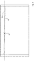
- camera
- angle
- industrial truck
- points
- Prior art date
- Legal status (The legal status is an assumption and is not a legal conclusion. Google has not performed a legal analysis and makes no representation as to the accuracy of the status listed.)
- Granted
Links
Images


Classifications
-
- G—PHYSICS
- G01—MEASURING; TESTING
- G01B—MEASURING LENGTH, THICKNESS OR SIMILAR LINEAR DIMENSIONS; MEASURING ANGLES; MEASURING AREAS; MEASURING IRREGULARITIES OF SURFACES OR CONTOURS
- G01B11/00—Measuring arrangements characterised by the use of optical techniques
- G01B11/26—Measuring arrangements characterised by the use of optical techniques for measuring angles or tapers; for testing the alignment of axes
-
- B—PERFORMING OPERATIONS; TRANSPORTING
- B65—CONVEYING; PACKING; STORING; HANDLING THIN OR FILAMENTARY MATERIAL
- B65G—TRANSPORT OR STORAGE DEVICES, e.g. CONVEYORS FOR LOADING OR TIPPING, SHOP CONVEYOR SYSTEMS OR PNEUMATIC TUBE CONVEYORS
- B65G1/00—Storing articles, individually or in orderly arrangement, in warehouses or magazines
- B65G1/02—Storage devices
- B65G1/04—Storage devices mechanical
- B65G1/0485—Check-in, check-out devices
-
- B—PERFORMING OPERATIONS; TRANSPORTING
- B65—CONVEYING; PACKING; STORING; HANDLING THIN OR FILAMENTARY MATERIAL
- B65G—TRANSPORT OR STORAGE DEVICES, e.g. CONVEYORS FOR LOADING OR TIPPING, SHOP CONVEYOR SYSTEMS OR PNEUMATIC TUBE CONVEYORS
- B65G1/00—Storing articles, individually or in orderly arrangement, in warehouses or magazines
- B65G1/02—Storage devices
- B65G1/04—Storage devices mechanical
- B65G1/0492—Storage devices mechanical with cars adapted to travel in storage aisles
-
- G—PHYSICS
- G01—MEASURING; TESTING
- G01B—MEASURING LENGTH, THICKNESS OR SIMILAR LINEAR DIMENSIONS; MEASURING ANGLES; MEASURING AREAS; MEASURING IRREGULARITIES OF SURFACES OR CONTOURS
- G01B11/00—Measuring arrangements characterised by the use of optical techniques
- G01B11/24—Measuring arrangements characterised by the use of optical techniques for measuring contours or curvatures
-
- G—PHYSICS
- G01—MEASURING; TESTING
- G01C—MEASURING DISTANCES, LEVELS OR BEARINGS; SURVEYING; NAVIGATION; GYROSCOPIC INSTRUMENTS; PHOTOGRAMMETRY OR VIDEOGRAMMETRY
- G01C3/00—Measuring distances in line of sight; Optical rangefinders
- G01C3/24—Measuring distances in line of sight; Optical rangefinders using a parallactic triangle with fixed angles and a base of variable length in the observation station, e.g. in the instrument
-
- G—PHYSICS
- G06—COMPUTING OR CALCULATING; COUNTING
- G06T—IMAGE DATA PROCESSING OR GENERATION, IN GENERAL
- G06T7/00—Image analysis
- G06T7/10—Segmentation; Edge detection
- G06T7/13—Edge detection
-
- G—PHYSICS
- G06—COMPUTING OR CALCULATING; COUNTING
- G06T—IMAGE DATA PROCESSING OR GENERATION, IN GENERAL
- G06T7/00—Image analysis
- G06T7/60—Analysis of geometric attributes
-
- G—PHYSICS
- G06—COMPUTING OR CALCULATING; COUNTING
- G06T—IMAGE DATA PROCESSING OR GENERATION, IN GENERAL
- G06T7/00—Image analysis
- G06T7/70—Determining position or orientation of objects or cameras
- G06T7/73—Determining position or orientation of objects or cameras using feature-based methods
-
- G—PHYSICS
- G06—COMPUTING OR CALCULATING; COUNTING
- G06T—IMAGE DATA PROCESSING OR GENERATION, IN GENERAL
- G06T2207/00—Indexing scheme for image analysis or image enhancement
- G06T2207/10—Image acquisition modality
- G06T2207/10004—Still image; Photographic image
-
- G—PHYSICS
- G06—COMPUTING OR CALCULATING; COUNTING
- G06T—IMAGE DATA PROCESSING OR GENERATION, IN GENERAL
- G06T2207/00—Indexing scheme for image analysis or image enhancement
- G06T2207/20—Special algorithmic details
- G06T2207/20024—Filtering details
-
- G—PHYSICS
- G06—COMPUTING OR CALCULATING; COUNTING
- G06T—IMAGE DATA PROCESSING OR GENERATION, IN GENERAL
- G06T2207/00—Indexing scheme for image analysis or image enhancement
- G06T2207/30—Subject of image; Context of image processing
- G06T2207/30248—Vehicle exterior or interior
- G06T2207/30252—Vehicle exterior; Vicinity of vehicle
Definitions
- the present invention relates to a method for orienting an industrial truck.
- Industrial trucks are regularly used in a warehouse environment to pick up and set down goods, loads and other items.
- the items to be transported by the industrial truck are usually transported on load carriers and stored, for example, on shelves and other storage locations.
- load carriers When picking up and setting down a load, it is important that the industrial truck picks up the load with the correct orientation.
- Orientation in relation to the load or a structure in the storage area describes, for example, an angle of the vehicle's longitudinal direction to an edge or surface of the structure. It is commonly said that an industrial truck approaches a rack or a load vertically in order to be able to pick up or set down the load.
- the object of the invention is to provide a method for determining an orientation of the industrial truck relative to a structure that can reliably determine the orientation of the industrial truck using the simplest possible means.
- the method according to the invention is intended and intended to determine an orientation of the industrial truck relative to a structure with horizontal elements.
- the industrial truck is equipped with a camera that is directed at the structure with the horizontal elements.
- the inventive The method has a series of steps that are run through, different sequences of the steps being possible, particularly in the case of the image processing steps.
- an image of the structure is recorded with at least one horizontal element.
- the picture of the structure is a two-dimensional picture that also includes the horizontal element. Due to the spatial orientation between the camera and the structure, horizontal lines in space are not horizontal in the recorded image.
- at least two geometric variables are determined in the recorded image. Geometric quantities can be points, lines, angles or fields.
- the geometric sizes are assigned to the horizontal element or part of the image of the horizontal element.
- an angle of intersection between an image plane and a vertical plane through the horizontal element is now determined using the at least two geometric variables.
- the basic idea here is that the two geometric quantities belong to an object running obliquely in the image and thus allow the angle of intersection to be identified, with the angle of intersection also being between a plane parallel to the image plane and a vertical plane through the horizontal element.
- an edge is identified in the recorded image.
- Edge detection in images is a method known per se.
- edges are preferably identified which, in terms of their position, can originate from horizontal structures in space.
- the two geometric variables are image coordinates of a reference point in the image and an angle of inclination of the edge in the image. From the reference size of the image coordinates (X, Y) and a Angle of inclination of the edge in the image, for example, a cutting angle can be determined by an assignment rule.
- the angle of the edge in the image is preferably determined for the angle of inclination of the edge.
- the slope of the edge in the image can be determined for this purpose.
- the two geometric variables form a distance and a distance angle to a point on the object.
- polar coordinates can be applied as the two geometric quantities, which, starting from the observing camera, describe a distance and an angle.
- the intersection angle of the horizontal structure with the image plane can be determined with the help of the distance and the angle.
- a further possibility for particularly favorable geometric variables consists in identifying at least two points along the identified edge.
- the points on the edge are preferably far apart in order to obtain as precise an angular resolution as possible.
- a ray is preferably determined in each case, the respective points of which are mapped onto the respective image point in a 3D coordinate system. These are rays from points in three-dimensional space that are mapped to the image point. With these rays, the angle of intersection can be determined for a pair of points, each with a point on the rays. The intersection angle is preferably calculated in the three-dimensional coordinate system.
- the camera is directed at a load shelf having one or more horizontal load shelf supports.
- the method according to the invention is therefore particularly suitable for industrial trucks that move in spatial areas in which there are a large number of horizontal elements.
- a load shelf with its horizontal load shelf supports can be recognized particularly easily and reliably in the course of image processing. No complex or otherwise sophisticated image processing is necessary to remove vertical or predominantly vertical edges from the recorded image and to determine horizontal or, depending on the orientation, approximately horizontal lines.
- the camera is attached to the industrial truck so that it has a defined orientation relative to the industrial truck and in particular relative to the longitudinal axis of the industrial truck even when the industrial truck is in operation. With the attachment, the camera is given a preferably predetermined orientation relative to the industrial truck.
- the camera is preferably mounted vertically on the industrial truck, so that the image plane of the camera is perpendicular to the longitudinal axis of the vehicle. In this way, the angle of intersection between the line connecting the points from the pair of points and the image plane can be converted directly into the orientation angle of the longitudinal axis of the vehicle relative to the horizontal element.
- a line outside the center of the image is selected for the at least one line to be evaluated. Lines outside the center of the image are viewed by the camera from a special perspective angle, which allows a more precise evaluation of the orientation.
- the camera is designed as a 2D camera.
- the camera is calibrated, i. H. their imaging ratios are known.
- a direction vector for the beam in the 3D coordinate system can be calculated for image coordinates from the imaging ratio.
- figure 1 shows a plan view of an industrial truck 10, which is designed in the example as a reach truck with two wheel arms 12, 14. Between the wheel arms 12, 14 there is a schematically illustrated mast 16 with two forks 18, 20 as load carrying means.
- a 2D camera 24 is attached to the rear wall 22 of the forks 18 , 20 .
- the 2D camera 24 is in figure 1 shown schematically and can be securely attached to the industrial truck for use so that it cannot be damaged or covered by a transported load. Also can in the industrial truck must be taken into account that the camera 24 changes its position with the mast 16.
- the change in position here consists in raising or lowering the camera 24 and in a forward or backward sliding of the mast relative to the wheel arms.
- the industrial truck stands with its longitudinal axis relative to a load shelf 28, which is shown in a plan view from above.
- the load shelf 28 has a front side 30 which faces the industrial truck 10 .
- the load shelf 28 has a rear side 32 on the side facing away from the industrial truck 10 .
- Between front 30 and back 32 is in figure 1 a view of three load aids 34a-c is shown.
- the load aids 34 are pallets stored in the load rack, which are shown empty for a better overview.
- figure 2 shows the image of the 2D camera 24 in a schematic view.
- the front side 30 of the load shelf 28 can be seen.
- the front side 30 of the shelf is formed by two vertical shelf supports 36a, b.
- Horizontally extending load shelf supports 38a, b, c are arranged between the shelf supports 36a, b.
- the term horizontal load shelf supports or elements is for figure 2 in need of explanation: As in figure 2 without further ado, the image of the load shelf supports is not horizontal.
- the left side of figure 2 appears larger and closer than the right side of the shelf. So there is a perspective taper in the image. Nevertheless, despite the tapered perspective in the picture, the load shelf support 38 is horizontal.
- Load aids 34 are located in the load shelf supports.
- the picture in figure 2 is a so-called gradient image, in which areas of the image that are spatially deep are filtered out and only the front side is shown in the image. Such focusing on the front edges facing the camera reduces the information content of the image because depth information is lost.
- figure 3 shows a further step in image processing, in which horizontal lines 40 are drawn into the image. These are determined from the existing image data, for example by edge extraction. In figure 3 It can be seen that the lines 40 formed do not run parallel to one another, but rather reflect the perspective tapering that results from the orientation of the industrial truck relative to the shelf.
- figure 4 shows a further step in which a first filtering towards the information-carrying edges takes place. Vertical lines are filtered out. Likewise, the constructed horizontal lines 40 are reduced back to the edges from the image.
- figure 5 shows the step of removing the horizontal lines in the image that pass roughly through the center of the image or an area around the center of the image. What remains are the information-carrying image edges 44, which most clearly show the tapered perspective.
- An image edge for example the image edge 46 of a stored pallet, is selected from these information-carrying image edges.
- the end points L 48 and R 50 are determined for this image edge 46 .
- Finding the endpoints is a common process in image processing.
- Points to the endpoints L and R figure 6 the geometric relationships.
- a vector leads from the camera 24 to the end point L 48 l ⁇ .
- the vector l ⁇ describes a ray 52 as does ray 54.
- figure 7 helps to understand the concept of rays.
- figure 7 shows the origin F c of the idealized camera 24. Attached to this is a right-hand oriented tripod X c , Y c and Z c .
- the Z-axis is the optical axis of the camera and likes the simplicity be thought of as parallel to the longitudinal direction of the vehicle.
- the camera 24 creates an image plane 56.
- the points in the image plane 56 can be described as u, v coordinates, as two-dimensional image coordinates.
- an image pixel is drawn in as an example in the first quadrant of the image. Since the imaging ratios of the camera 24 are known, a ray 58 can be constructed for the pixel (u, v).
- Each point P on ray 58 is mapped onto the camera's image at pixel (u,v).
- This system thus describes how a ray 58 can be constructed from the pixel values for a camera whose imaging ratios are known.
- figure 7 also clearly shows that the distance of the point P from the camera 24 cannot be determined from the image point (u,v). This is also not surprising since the three-dimensional coordinates are mapped onto the two-dimensional image using the camera.
- the focal length of the camera in particular the three axes X c , Y c and Z c , must be determined for the reconstruction of the beam with the possible image points P. be known.
- n n ⁇ right e.g ⁇ l y right y ⁇ l e.g .
- the quantities included in the equation are the coordinates from the rays leading to the points. These coordinates depend on the focal length f x f y of the camera 24 in the X and Y directions.
- the variables x' and y' are auxiliary variables which, together with the focal lengths f x , f y and the image center c x , y x , describe the imaging in the image coordinates UV.
- the result for the three-dimensional coordinates (X, Y, Z) is the beam in the three-dimensional coordinates with a direction (X', Y', 1) . It should be noted that this direction vector of the ray is not normalized, but this is not necessary for the further calculation.
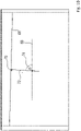
- the example in 9 shows an image with an edge 60 drawn in.
- the edge 60 is inclined relative to the horizontal 62 .
- a point 64 on the edge 60 is also determined in the image.
- a wide variety of approaches can be chosen for determining the point 64 .
- the center of edge 60 can be chosen.
- a point 64 can also be selected in which the enclosed image area between the edge 60 and the horizontal 62 on both sides of the point 64 is the same.
- the evaluation of the edge 60 results in two geometric variables, the point and the angle, which can be denoted overall as (X, Y, ⁇ ).
- the look-up table can be calculated in advance and is therefore accessible for a quick evaluation.
- a look-up table can prove to be helpful, particularly given the fact that many edges in the image are to be evaluated.
- FIG. 10 shows a very similar situation as in 9 , in which an edge 66 runs obliquely in the image.
- a distance r, 72 and an angle ⁇ , 74 are determined to determine the two geometric variables.
- the angle 74 is fixed in relation to a horizontal line 68 .
- distance 72 is perpendicular to edge 66.
- the distance could also be perpendicular to horizontal 68 and intersect edge 66 at an angle of inclination.
- a cutting angle is looked up and used, for example via a look-up table for the geometric variables r, ⁇ . If different angles of intersection arise for several points 70 or several edges 66, these can be evaluated statistically.
Landscapes
- Engineering & Computer Science (AREA)
- Physics & Mathematics (AREA)
- General Physics & Mathematics (AREA)
- Computer Vision & Pattern Recognition (AREA)
- Theoretical Computer Science (AREA)
- Mechanical Engineering (AREA)
- Geometry (AREA)
- Electromagnetism (AREA)
- Radar, Positioning & Navigation (AREA)
- Remote Sensing (AREA)
- Length Measuring Devices By Optical Means (AREA)
- Image Analysis (AREA)
Abstract
Description
- Die vorliegende Erfindung betrifft ein Verfahren zur Orientierung eines Flurförderzeugs.
- Flurförderzeuge werden regelmäßig in einer Lagerumgebung eingesetzt, um Waren, Lasten und andere Gegenstände aufzunehmen und abzusetzen. Die von dem Flurförderzeug zu transportierenden Gegenstände werden in der Regel auf Lastträgern transportiert und beispielsweise in Regalen und anderen Lagerplätzen gelagert. Für das Aufnehmen und Absetzen einer Last ist es wichtig, dass das Flurförderzeug die Last unter einer richtigen Orientierung aufnimmt. Orientierung gegenüber der Last oder einer Struktur im Lagerbereich bezeichnet beispielsweise einen Winkel der Fahrzeuglängsrichtung zu einer Kante oder Fläche der Struktur. Gemeinhin spricht man davon, dass ein Flurförderzeug ein Regal oder eine Last senkrecht anfährt, um die Last aufnehmen oder absetzen zu können.
- Die erfindungsgemäße Aufgabe besteht darin, ein Verfahren zur Bestimmung einer Orientierung des Flurförderzeugs relativ zu einer Struktur bereitzustellen, das mit möglichst einfachen Mitteln zuverlässig die Orientierung des Flurförderzeugs ermitteln kann.
- Erfindungsgemäß wird die Aufgabe durch ein Verfahren mit den Merkmalen nach Anspruch 1 gelöst. Vorteilhafte Ausgestaltungen bilden die Gegenstände der Unteransprüche.
- Das erfindungsgemäße Verfahren ist vorgesehen und bestimmt, eine Orientierung des Flurförderzeugs relativ zu einer Struktur mit horizontalen Elementen zu ermitteln. Das Flurförderzeug ist bei dem Verfahren mit einer Kamera ausgestattet, die auf die Struktur mit den horizontalen Elementen gerichtet ist. Das erfindungsgemäße Verfahren besitzt eine Reihe von Schritten, die durchlaufen werden, wobei insbesondere bei den Schritten der Bildverarbeitung verschiedene Reihenfolgen der Schritte möglich sind. Bei dem erfindungsgemäßen Verfahren erfolgt das Aufzeichnen eines Bildes der Struktur mit mindestens einem horizontalen Element. Es ist dabei so, dass das Bild der Struktur ein zweidimensionales Bild ist, das auch das horizontale Element beinhaltet. Aufgrund der räumlichen Orientierung zwischen der Kamera und der Struktur verlaufen horizontale Linien im Raum nicht horizontal in dem aufgezeichneten Bild. In einem weiteren Schritt werden mindestens zwei geometrische Größen in dem aufgezeichneten Bild bestimmt. Bei geometrischen Größen kann es sich um Punkte, Linien, Winkel oder Felder handeln. Die geometrischen Größen sind dabei dem horizontalen Element zugeordnet bzw. Teil der Abbildung des horizontalen Elements. Erfindungsgemäß wird nun unter Verwendung der mindestens zwei geometrischen Größen ein Schnittwinkel zwischen einer Bildebene und einer vertikalen Ebene durch das horizontale Element bestimmt. Der grundlegende Gedanke hierbei ist, dass die beiden geometrischen Größen zu einem schräg im Bild verlaufenden Gegenstand gehören und somit eine Identifikation des Schnittwinkels zulassen, wobei der Schnittwinkel auch zwischen einer zur Bildebene parallelen Ebene und einer vertikalen Ebene durch das horizontale Element vorliegt.
- In einer bevorzugten Ausgestaltung wird in dem aufgezeichneten Bild eine Kante identifiziert. Die Kantendetektion in Bildern ist ein an sich bekanntes Verfahren. Bei dem erfindungsgemäßen Verfahren werden bevorzugt Kanten identifiziert, die ihrer Lage nach von horizontalen Strukturen im Raum stammen können.
- In einer bevorzugten Ausgestaltung sind die beiden geometrischen Größen Bildkoordinaten eines Bezugspunkts in dem Bild und ein Neigungswinkel der Kante in dem Bild. Aus der Bezugsgröße der Bildkoordinaten (X, Y) und einem Neigungswinkel der Kante im Bild kann beispielsweise durch eine Zuordnungsvorschrift ein Schnittwinkel bestimmt werden.
- Für den Neigungswinkel der Kante wird dabei bevorzugt der Winkel der Kante im Bild bestimmt. Hierzu kann beispielsweise die Steigung der Kante im Bild bestimmt werden.
- In einer alternativen Ausgestaltung, die selbstverständlich auch zusätzlich verwendet werden kann, bilden die zwei geometrischen Größen einen Abstand und einen Abstandswinkel zu einem Punkt des Gegenstands. Hier können als die beiden geometrischen Größen Polarkoordinaten angesetzt werden, die, ausgehend von der beobachtenden Kamera, einen Abstand und einen Winkel beschreiben. Auch hier kann mit Hilfe des Abstandes und des Winkels der Schnittwinkel der horizontalen Struktur mit der Bildebene bestimmt werden.
- Eine weitere Möglichkeit für besonders günstige geometrische Größen besteht darin, entlang der identifizierten Kante mindestens zwei Punkte zu identifizieren. Bevorzugt liegen die Punkte auf der Kante weit auseinander, um möglichst eine genaue Winkelauflösung zu bekommen.
- Bevorzugt wird, ausgehend von den zwei Punkten, jeweils ein Strahl bestimmt, dessen jeweiligen Punkte in einem 3D-Koordinatensystem auf den jeweiligen Bildpunkt abgebildet werden. Es handelt es sich hierbei um Strahlen von Punkten im dreidimensionalen Raum, die auf den Bildpunkt abgebildet werden. Bei diesen Strahlen kann für ein Punktpaar mit jeweils einem Punkt auf den Strahlen der Schnittwinkel bestimmt werden. Bevorzugt erfolgt hierbei die Berechnung des Schnittwinkels im dreidimensionalen Koordinatensystem.
- Die vorstehend aufgezählten drei Möglichkeiten sind hierbei lediglich Beispiele für zwei aus dem Bild gewonnene geometrische Größen, die eine Bestimmung des Schnittwinkels zwischen der Bildebene und der Struktur mit dem horizontalen Element zulassen. Weitere Paare von geometrischen Größen sind ebenfalls möglich.
- In einer bevorzugten Ausgestaltung wird die Kamera auf ein Lastregal mit einem oder mehreren horizontalen Lastregalträgern gerichtet. Das erfindungsgemäße Verfahren ist damit besonders für Flurförderzeuge geeignet, die sich in Raumbereichen bewegen, in denen eine Vielzahl von horizontalen Elementen vorliegt. Ein Lastregal mit seinen horizontalen Lastregalträgern ist im Zuge der Bildverarbeitung besonders einfach und zuverlässig erkennbar. Es ist keine aufwändige oder sonst wie ausgefeilte Bildverarbeitung notwendig, um vertikale oder überwiegend vertikale Kanten aus dem aufgezeichneten Bild zu entfernen und horizontale bzw. je nach Orientierung annähernd horizontale Linien zu bestimmen.
- In einer bevorzugten Weiterbildung wird die Kamera an dem Flurförderzeug angebracht, so dass sie auch im Betrieb des Flurförderzeugs eine definierte Orientierung relativ zu dem Flurförderzeug und insbesondere relativ zu der Längsachse des Flurförderzeugs besitzt. Mit der Anbringung erhält die Kamera eine bevorzugt vorbestimmte Orientierung relativ zu dem Flurförderzeug. Bevorzugt ist die Kamera vertikal an dem Flurförderzeug angebracht, so dass die Bildebene der Kamera senkrecht zur Fahrzeuglängsachse steht. Auf diese Weise kann der Schnittwinkel zwischen der Verbindungslinie der Punkte aus dem Punktpaar und der Bildebene direkt in den Orientierungswinkel der Fahrzeuglängsachse zu dem horizontalen Element umgerechnet werden.
- Als besonders vorteilhaft hat es sich herausgestellt, aus dem aufgezeichneten Bild vertikale Bildkanten herauszufiltern. Indem das Herausfiltern beispielsweise vorgenommen wird, bevor die Linie zu dem horizontalen Element ermittelt wird, vermeiden die fehlenden vertikalen Linien Fehler beim Ermitteln der Linien zu dem horizontalen Element. In einer bevorzugten Ausgestaltung wird für die mindestens eine auszuwertende Linie eine Linie außerhalb der Bildmitte gewählt. Linien außerhalb der Bildmitte werden unter einem besonderen perspektivischen Winkel von der Kamera betrachtet, der eine genauere Auswertung der Orientierung zulässt.
- In einer bevorzugten Weiterbildung ist die Kamera als eine 2D-Kamera ausgebildet. Zudem ist die Kamera kalibriert, d. h. ihre Abbildungsverhältnisse sind bekannt. Aus dem Abbildungsverhältnis kann für Bildkoordinaten ein Richtungsvektor für den Strahl in dem 3D-Koordinatensystem berechnet werden. Bei dieser Umrechnung werden die beiden in der Ebene liegenden Bildpunkte in den Strahl umgerechnet, wobei alle Punkte im 3D-Koordinatensystem, die auf dem Strahl liegen, durch die Kamera auf den Bildpunkt abgebildet.
- Es hat sich als besonders vorteilhaft herausgestellt, nicht nur mit einem Punktpaar zu arbeiten, sondern zur Bestimmung des Orientierungswinkels eine Vielzahl von Punktpaaren einzusetzen und die gewonnenen Ergebnisse wie unabhängige Messungen statistisch auszuwerten, beispielsweise mit dem Mittelwert.
- Die Erfindung wird nachfolgend an einem Ausführungsbeispiel näher erläutert. Es zeigen:
- Fig. 1
- eine Draufsicht auf ein Flurförderzeug vor einem Lastregal,
- Fig. 2
- eine schräge Sicht auf das Lastregal,
- Fig. 3
- die Konstruktion von horizontalen Bildkanten, die waagerechten Elementen entsprechen,
- Fig. 4
- das Ergebnis einer ersten Filterung, bei der vertikale Linien unterdrückt sind,
- Fig. 5
- ein Abstellen auf die außermittigen horizontalen Bildlinien,
- Fig. 6
- die Bestimmung der Endpunkte L, R bei einer horizontalen Linie als Durchstoßpunkte einer horizontalen Ebene,
- Fig. 7
- die Umrechnung der Bildpunkte in einem Strahl mit 3D-Koordinaten,
- Fig. 8
- die Berechnung des Winkels zur Orientierung des Flurförderzeugs relativ zu der Bildebene,
- Fig. 9
- in einer schematischen Ansicht eine schräg im Bild verlaufende Kante, zu der ein Bildpunkt und ein Neigungswinkel α bestimmt wird und
- Fig. 10
- die Bestimmung der geometrischen Größen als Polarkoordinaten.
-
Figur 1 zeigt in einer Draufsicht ein Flurförderzeug 10, das in dem Beispiel als Schubmaststapler mit zwei Radarmen 12, 14 ausgebildet ist. Zwischen den Radarmen 12, 14 befindet sich ein schematisch dargestelltes Hubgerüst 16 mit zwei Gabelzinken 18, 20 als Lasttragmittel. An der Rückwand 22 der Gabelzinken 18, 20 ist eine 2D-Kamera 24 angebracht. Die 2D-Kamera 24 ist inFigur 1 schematisch dargestellt und kann für den Einsatz am Flurförderzeug sicher angebracht werden, so dass sie nicht von einer transportierten Last beschädigt oder verdeckt werden kann. Auch kann in dem Flurförderzeug berücksichtigt werden, dass die Kamera 24 mit dem Hubgerüst 16 ihre Position ändert. Die Positionsänderung besteht hierbei im Anheben oder Senken der Kamera 24 und in einem Vor- oder Zurückschieben des Hubgerüsts relativ zu den Radarmen. - Das Flurförderzeug steht mit seiner Längsachse relativ zu einem Lastregal 28, das in einer Draufsicht von oben dargestellt ist. Das Lastregal 28 besitzt ein Frontseite 30, die dem Flurförderzeug 10 zugewandt ist. Ebenso besitzt das Lastregal 28 eine Rückseite 32 auf der dem Flurförderzeug 10 abgewandten Seite. Zwischen Frontseite 30 und Rückseite 32 ist in
Figur 1 ein Blick auf drei Lasthilfsmittel 34a-c dargestellt. Bei den Lasthilfsmitteln 34 handelt es sich jeweils um in das Lastregal eingelagerte Paletten, die zur besseren Übersicht leer dargestellt sind. -
Figur 2 zeigt in einer schematischen Ansicht das Bild der 2D-Kamera 24. Zu erkennen ist die Frontseite 30 des Lastregals 28. Die Frontseite 30 des Regals wird von zwei vertikalen Regalstützen 36a, b gebildet. Zwischen den Regalstützen 36a, b angeordnet sind horizontal verlaufende Lastregalträger 38a, b, c. Der Begriff horizontal verlaufende Lastregalträger oder Elemente ist fürFigur 2 erläuterungsbedürftig: Wie inFigur 2 ohne weiteres zu kennen, verläuft das Bild der Lastregalträger nicht horizontal. Die linke Seite vonFigur 2 wirkt größer und näher als die rechte Seite des Regals. Es liegt also eine perspektivische Verjüngung in dem Bild vor. Gleichwohl ist trotz der perspektivischen Verjüngung im Bild der Lastregalträger 38 horizontal. In den Lastregalträgern sind Lasthilfsmittel 34 eingezeichnet. Das Bild inFigur 2 ist ein sogenanntes Gradientenbild, bei dem räumlich in die Tiefe gehende Bereiche des Bildes herausgefiltert sind und nur die vordere Seite im Bild dargestellt ist. Ein solches Abstellen auf die vorderen, der Kamera zugewandten Kanten reduziert den Informationsgehalt des Bildes, weil Tiefeninformationen verlorengehen. -
Figur 3 zeigt einen weiteren Schritt der Bildverarbeitung, in dem horizontale Linien 40 in das Bild eingezeichnet werden. Diese werden aus den vorhandenen Bilddaten ermittelt, beispielsweise durch Kantenextraktion. InFigur 3 ist zu erkennen, dass die gebildeten Linien 40 nicht parallel zueinander verlaufen, sondern die perspektivische Verjüngung, die sich aus der Orientierung des Flurförderzeugs gegenüber dem Regal ergibt, widerspiegeln. -
Figur 4 zeigt einen weiteren Schritt, bei dem eine erste Filterung hin zu den informationstragenden Kanten erfolgt. Vertikale Linien werden hierbei herausgefiltert. Ebenso werden die konstruierten horizontalen Linien 40 wieder auf die Kanten aus dem Bild reduziert. -
Figur 5 zeigt den Schritt, dass die horizontalen Linien im Bild, die ungefähr durch die Bildmitte oder einen Bereich um die Bildmitte verlaufen, herausgenommen werden. Übrig bleiben die informationstragenden Bildkanten 44, die am deutlichsten, die perspektivische Verjüngung zeigen. - Aus diesen informationstragenden Bildkanten wird eine Bildkante, beispielsweise die Bildkante 46 einer gelagerten Palette herausgegriffen. Für diese Bildkante 46 werden Punkte hier beispielsweise die Endpunkte L 48 und R 50 bestimmt. Das Herausfinden der Endpunkte ist ein in der Bildverarbeitung geläufiger Vorgang. Zu den Endpunkten L und R zeigt
Figur 6 die geometrischen Verhältnisse. Ausgehend von der Kamera 24 führt zu dem Endpunkt L 48 ein Vektor

-
Figur 7 hilft das Konzept der Strahlen zu verstehen.Figur 7 zeigt den Ursprung Fc der idealisierten Kamera 24. Hieran hängt ein rechtshändig orientiertes Dreibein Xc, Yc und Zc. Die Z-Achse sei die optische Achse der Kamera und möge der Einfachheit halber als parallel zur Fahrzeuglängsrichtung gedacht werden. Die Kamera 24 erzeugt eine Bildebene 56. Die Punkte in der Bildebene 56 können als u-, v-Koordinaten, als zweidimensionale Bildkoordinaten beschrieben werden. InFigur 7 ist beispielhaft ein Bildpixel im ersten Quadranten des Bildes eingezeichnet. Da die Abbildungsverhältnisse der Kamera 24 bekannt sind, kann zu dem Bildpunkt (u, v) ein Strahl 58 konstruiert werden. Jeder Punkt P auf dem Strahl 58 wird auf dem Bild der Kamera in dem Pixel (u, v) abgebildet. Dieses System beschreibt also, wie aus den Pixelwerten für eine Kamera, deren Abbildungsverhältnisse bekannt sind, ein Strahl 58 konstruiert werden kann.Figur 7 zeigt auch anschaulich, dass die Entfernung des Punktes P von der Kamera 24 nicht aus dem Bildpunkt (u,v) ermittelt werden kann. Dies ist auch nicht verwunderlich, da die dreidimensionalen Koordinaten mithilfe der Kamera auf das zweidimensionale Bild abgebildet werden. Für die Kamera 24 muss zur Rekonstruktion des Strahls mit den möglichen Bildpunkten P die Brennweite der Kamera, insbesondere der drei Achsen Xc, Yc und Zc. bekannt sein. - Betrachten wir noch einmal
Figur 6 . Hier gibt es zwei Richtungsvektoren L-Vektor


Figur 6 dargestellt. Sie besitzt den inFigur 6 dargestellten Verlauf. - Den letzten Schritt verdeutlicht
Figur 8 . Hier ist das Kameradreibein in der Durchstoßebene mit seinen X-, Z-Koordinaten dargestellt. Nun ist bekannt, dass die beiden Punkte, die auf den Strahlen L, R liegen, die gleiche Y-Koordinate besitzen. Hieraus werden dann die gleichen Koordinaten errechnet. Es sei:

- Unter der Annahme, dass die Y-Koordinaten der beiden Strahlen L und R gleich sind ergibt sich:

- Aus diesen beiden Gleichungen ergibt sich durch einfaches Umformen, dass das dargestellte Dreieck in
Figur 8 für den Winkel α eine Ankathete der Länge a besitzt: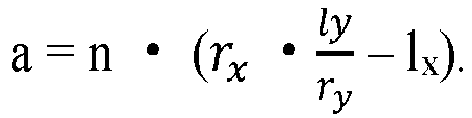
- Die Größe der Gegenkathete b kann ebenfalls direkt abgelesen werden und ergibt sich zu:

- Das Besondere an dem erfindungsgemäßen Ansatz ist nur, dass sich für die Berechnung des Winkels α die Unbekannte n heraus kürzt. Betrachten wir den Tangens des Orientierungswinkels so ergibt sich:


- Die in der Gleichung enthaltenen Größen sind die Koordinaten aus den Strahlen, die zu den Punkten führen. Diese Koordinaten sind abhängig von der Brennweite fxfy der Kamera 24 in Richtung der X- und der Y-Richtung. Die Berechnung dieser Koordinaten aus den Bildkoordinaten ist hinlänglich bekannt, und ergibt sich aus der folgenden Gleichung:


- Die Größen x' und y' sind Hilfsgrößen, die zusammen mit den Brennweiten fx, fy und dem Bildzentrum cx, yx die Abbildung in den Bildkoordinaten UV beschreibt. Durch eine einfache Umformung ergibt sich folgender Zusammenhang:


- Zusammen mit den aus der Kamerakalibrierung bekannten Größen cx, cy, fx, fy ergibt sich für die dreidimensionalen Koordinaten (X, Y, Z) der Strahl in den dreidimensionalen Koordinaten mit einer Richtung (X', Y', 1). Zu beachten ist, dass dieser Richtungsvektor des Strahls nicht normiert ist, was aber auch für die weitere Berechnung nicht erforderlich ist.
- Das Beispiel in
Fig. 9 zeigt ein Bild mit einer eingezeichneten Kante 60. Die Kante 60 ist gegenüber der Horizontalen 62 geneigt. In dem Bild wird zudem ein Punkt 64 auf der Kante 60 bestimmt. Für die Bestimmung des Punktes 64 können verschiedenste Ansätze gewählt werden. Beispielsweise kann die Mitte der Kante 60 gewählt werden. Es kann aber auch ein Punkt 64 gewählt werden, bei dem die eingeschlossene Bildfläche zwischen der Kante 60 und der Horizontalen 62 auf beiden Seiten des Punktes 64 gleich groß ist. Aus der Auswertung der Kante 60 ergeben sich mit dem Punkt und dem Winkel zwei geometrische Größen, die insgesamt als (X, Y, α) bezeichnet werden können. Für die Auswertung ist es nun möglich, beispielsweise in einer Look-Up-Tabelle zu den Werten X, Y, α einen Schnittwinkel nachzusehen. Die Look-Up-Tabelle kann bereits im Vorfeld berechnet werden und ist damit für eine schnelle Auswertung zugänglich. Insbesondere unter dem Aspekt, dass viele Kanten in dem Bild ausgewertet werden sollen, kann sich eine Look-Up-Tabelle als hilfreich erweisen. -
Fig. 10 zeigt eine sehr ähnliche Situation wie inFig. 9 , bei der eine Kante 66 schräg im Bild verläuft. Zur Bestimmung der beiden geometrischen Größen wird, ausgehend von einem Punkt 70, auf der Kante 66 wird ein Abstand r, 72 und ein Winkel ϕ, 74 bestimmt. Der Winkel 74 ist hierbei gegenüber einer Horizontalen 68 festgelegt. Der Abstand 72 steht in diesem Beispiel senkrecht auf der Kante 66. Grundsätzlich könnte der Abstand auch senkrecht auf der Horizontalen 68 stehen und unter einem Neigungswinkel die Kante 66 schneiden. - Auch bei diesem Ansatz wird beispielsweise über eine Look-Up-Tabelle für die geometrischen Größen r, ϕ ein Schnittwinkel nachgesehen und verwendet. Sollten für mehrere Punkte 70 oder mehrere Kanten 66 unterschiedliche Schnittwinkel entstehen, so können diese statistisch ausgewertet werden.
-
- 10
- Flurförderzeug
- 12
- Radarm
- 14
- Radarm
- 16
- Hubgerüst
- 18
- Gabelzinken
- 20
- Gabelzinken
- 22
- Rückwand
- 24
- 2D-Kamera
- 28
- Lastregal
- 30
- Frontseite des Lastregals
- 32
- Rückseite des Lastregals
- 34a-c
- Lasthilfsmittel
- 36a-b
- Regalstützen
- 38a-c
- Lastregalträger
- 40
- horizontale Linien
- 44
- Bildkante
- 46
- Bildkante
- 48
- Endpunkt L
- 50
- Endpunkt R
- 52
- Strahl
- 56
- Bildebene
- 58
- Strahl
- 60
- Kante
- 62
- Horizontale
- 64
- Punkt
- 66
- Kante
- 68
- Horizontale
- 70
- Punkt
- 72
- Abstand r
- 74
- Winkel ϕ
Claims (15)
- Verfahren zur Bestimmung einer Orientierung eines Flurförderzeugs (10) relativ zu einer Struktur mit mindestens einem horizontalen Element, wobei das Flurförderzeug (10) eine Kamera (24) aufweist, die auf die Struktur gerichtet ist, wobei das Verfahren die folgenden Verfahrensschritte aufweist:∘ Aufzeichnen eines Bildes der Struktur mit dem mindestens einem horizontalen Element,∘ Bestimmen von mindestens zwei geometrischen Größen in dem aufgezeichneten Bild, die dem horizontalen Element entsprechen, und∘ Bestimmen eines Schnittwinkels zwischen einer Bildebene (56) und einer vertikalen Ebene durch das horizontale Element aus den mindestens zwei geometrischen Größen.
- Verfahren nach Anspruch 1, dadurch gekennzeichnet, dass in dem aufgezeichneten Bild eine Kante identifiziert wird.
- Verfahren nach Anspruch 2, dadurch gekennzeichnet, dass die mindestens zwei geometrischen Größen zwei Bildkoordinaten eines Bezugspunktes in dem Bild und einen Neigungswinkel der Kante enthalten.
- Verfahren nach Anspruch 3, dadurch gekennzeichnet, dass der Neigungswinkel als Winkel der Kante im Bild bestimmt wird.
- Verfahren nach Anspruch 2, dadurch gekennzeichnet, dass die mindestens zwei geometrischen Größen einen Abstand und einen Abstandswinkel enthalten.
- Verfahren nach einem der vorherigen Ansprüche, dadurch gekennzeichnet, dass als geometrische Größe in dem aufgezeichneten Bild entlang der identifizierten Kante mindestens zwei Punkte (L, R) (48, 50) identifiziert werden.
- Verfahren nach Anspruch 6, dadurch gekennzeichnet, dass jeweils ein Strahl (
l ,r ) (52, 58) zu einem der beiden Punkte (L, R) bestimmt wird, dessen jeweilige Punkte in einem 3D-Koordinatensystem auf den jeweiligen Punkt (L, R) im Bild abgebildet werden. - Verfahren nach Anspruch 7, dadurch gekennzeichnet, dass von mindestens einem Punktpaar mit jeweils einem Punkt in einem der beiden Strahlen (52, 58) in dem 3D-Koordinatensystem der Schnittwinkel bestimmt wird.
- Verfahren nach einem der vorherigen Ansprüche, dadurch gekennzeichnet, dass die Kamera (24) auf ein Lastregal (28) mit horizontalen Lastregalträgern (38a-c) gerichtet wird.
- Verfahren nach einem der vorherigen Ansprüche, dadurch gekennzeichnet, dass die Kamera (24) an dem Flurförderzeug (10) angebracht ist.
- Verfahren nach einem der vorherigen Ansprüche, dadurch gekennzeichnet, dass die Bildebene der Kamera (24) eine vorbestimmte Orientierung, insbesondere eine vertikale Orientierung an dem Flurförderzeug (10) aufweist.
- Verfahren nach einem der vorherigen Ansprüche, dadurch gekennzeichnet, dass in dem aufgezeichneten Bild vertikale Kanten herausgefiltert werden.
- Verfahren nach einem der vorherigen Ansprüche, dadurch gekennzeichnet, dass Linien in einem Bericht der Bildmitte herausgefiltert werden.
- Verfahren nach einem der vorherigen Ansprüche, dadurch gekennzeichnet, dass die Kamera (24) kalibriert ist und ein Punkt mit den Bildkoordinaten (u, v) in einen Richtungsvektor (x', y', 1) für einen Strahl umgerechnet wird, dessen Punkte in dem 3D-Koordinatensystem jeweils auf den Punkt mit den Bildkoordinaten abgebildet werden.
- Verfahren nach einem der vorherigen Ansprüche, dadurch gekennzeichnet, dass eine Vielzahl der jeweils mindesten zwei geometrischen Größen ausgewertet wird, wobei die sich ergebende Vielzahl von Schnittwinkeln statistisch ausgewertet wird.
Applications Claiming Priority (1)
| Application Number | Priority Date | Filing Date | Title |
|---|---|---|---|
| DE102021102633.4A DE102021102633A1 (de) | 2021-02-04 | 2021-02-04 | Verfahren zur Bestimmung einer Orientierung eines Flurförderzeugs |
Publications (2)
| Publication Number | Publication Date |
|---|---|
| EP4040390A1 true EP4040390A1 (de) | 2022-08-10 |
| EP4040390B1 EP4040390B1 (de) | 2025-05-07 |
Family
ID=80119389
Family Applications (1)
| Application Number | Title | Priority Date | Filing Date |
|---|---|---|---|
| EP22154327.5A Active EP4040390B1 (de) | 2021-02-04 | 2022-01-31 | Verfahren zur bestimmung einer orientierung eines flurförderzeugs |
Country Status (4)
| Country | Link |
|---|---|
| US (1) | US12154292B2 (de) |
| EP (1) | EP4040390B1 (de) |
| CN (1) | CN114858085B (de) |
| DE (1) | DE102021102633A1 (de) |
Citations (3)
| Publication number | Priority date | Publication date | Assignee | Title |
|---|---|---|---|---|
| EP3151199A2 (de) * | 2015-09-30 | 2017-04-05 | Ricoh Company, Ltd. | Algorithmus zur schätzung von gierfehlern in einer kameraposition |
| US20190096080A1 (en) * | 2017-08-25 | 2019-03-28 | Maker Trading Pte Ltd | Machine vision system and method for identifying locations of target elements |
| US20200380694A1 (en) * | 2019-06-03 | 2020-12-03 | Zebra Technologies Corporation | Method, System and Apparatus for Shelf Edge Detection |
Family Cites Families (12)
| Publication number | Priority date | Publication date | Assignee | Title |
|---|---|---|---|---|
| JP3663263B2 (ja) * | 1996-10-24 | 2005-06-22 | 株式会社ダイフク | 搬送車 |
| JP3690260B2 (ja) | 2000-10-18 | 2005-08-31 | 日産自動車株式会社 | 車間距離計測方法 |
| DE202006012637U1 (de) | 2006-08-16 | 2006-11-16 | Sick Ag | Vorrichtung zum Kollisionsschutz zwischen aufeinanderfolgenden spurgeführten Fahrzeugen |
| JP2008309595A (ja) | 2007-06-13 | 2008-12-25 | Horiba Ltd | オブジェクト認識装置及びそれに用いられるプログラム |
| DE102008041761A1 (de) | 2008-09-02 | 2010-03-04 | Robert Bosch Gmbh | Verfahren und Vorrichtung zur Ermittlung eines relativen Gierwinkels |
| RU2009113008A (ru) * | 2009-04-08 | 2010-10-20 | Михаил Юрьевич Воробьев (RU) | Способ определения позиции и ориентации прицепа транспортного средства и устройство для его осуществления |
| DE102010056217A1 (de) | 2010-12-24 | 2012-06-28 | Valeo Schalter Und Sensoren Gmbh | Verfahren zum Betreiben eines Fahrerassistenzsystems in einem Kraftfahrzeug, Fahrerassistenzsystem und Kraftfahrzeug |
| DE102013002554A1 (de) | 2013-02-15 | 2014-08-21 | Jungheinrich Aktiengesellschaft | Verfahren zur Erkennung von Objekten in einem Lager und/oder zur räumlichen Orientierung in einem Lager |
| FR3034555B1 (fr) * | 2015-04-03 | 2017-04-21 | Continental Automotive France | Procede de determination du sens du mouvement d'un vehicule automobile |
| EP3174007A1 (de) * | 2015-11-30 | 2017-05-31 | Delphi Technologies, Inc. | Verfahren zur kalibrierung der ausrichtung einer an ein fahrzeug montierten kamera |
| CN110222700A (zh) * | 2019-05-30 | 2019-09-10 | 五邑大学 | 基于多尺度特征与宽度学习的sar图像识别方法及装置 |
| JP7136141B2 (ja) * | 2020-02-07 | 2022-09-13 | カシオ計算機株式会社 | 情報管理装置、情報管理方法及びプログラム |
-
2021
- 2021-02-04 DE DE102021102633.4A patent/DE102021102633A1/de active Pending
-
2022
- 2022-01-29 CN CN202210109551.6A patent/CN114858085B/zh active Active
- 2022-01-31 EP EP22154327.5A patent/EP4040390B1/de active Active
- 2022-02-03 US US17/591,662 patent/US12154292B2/en active Active
Patent Citations (3)
| Publication number | Priority date | Publication date | Assignee | Title |
|---|---|---|---|---|
| EP3151199A2 (de) * | 2015-09-30 | 2017-04-05 | Ricoh Company, Ltd. | Algorithmus zur schätzung von gierfehlern in einer kameraposition |
| US20190096080A1 (en) * | 2017-08-25 | 2019-03-28 | Maker Trading Pte Ltd | Machine vision system and method for identifying locations of target elements |
| US20200380694A1 (en) * | 2019-06-03 | 2020-12-03 | Zebra Technologies Corporation | Method, System and Apparatus for Shelf Edge Detection |
Also Published As
| Publication number | Publication date |
|---|---|
| EP4040390B1 (de) | 2025-05-07 |
| CN114858085B (zh) | 2026-06-30 |
| DE102021102633A1 (de) | 2022-08-04 |
| US12154292B2 (en) | 2024-11-26 |
| CN114858085A (zh) | 2022-08-05 |
| US20220245854A1 (en) | 2022-08-04 |
Similar Documents
| Publication | Publication Date | Title |
|---|---|---|
| EP2275990B1 (de) | 3D-Sensor | |
| DE69627765T2 (de) | Verfahren und Vorrichtung zur Raumfilterung von verrauschten numerischen Bildern | |
| DE102022120971B4 (de) | Gabelstapler und Verfahren zur Erfassung der Beladungsposition für einen Gabelstapler | |
| EP3316181B1 (de) | Verfahren zum erkennen von objekten in einem lager und flurförderzeug mit einer einrichtung zum erkennen von objekten in einem lager | |
| DE102006003538B3 (de) | Verfahren zum Zusammenfügen mehrerer Bildaufnahmen zu einem Gesamtbild in der Vogelperspektive | |
| EP2767925B1 (de) | Verfahren zur Erkennung von Objekten in einem Lager und/oder zur räumlichen Orientierung in einem Lager | |
| EP1987371B1 (de) | Verfahren zur detektion von objekten mit einer schwenkbaren sensoreinrichtung | |
| DE4130010C2 (de) | Vorrichtung zur laufenden Beobachtung eines Fahrzeuges und zur Messung seines Abstandes | |
| DE102018122374B4 (de) | Verfahren zum Bestimmen eines ein Kraftfahrzeug umgebenden Freiraums, Computerprogrammprodukt, Freiraumbestimmungseinrichtung und Kraftfahrzeug | |
| EP3403404B1 (de) | Stereobilderfassungssystem | |
| DE102008019373A1 (de) | Messvorrichtung und Verfahren zum Kalibrieren einer Messvorrichtung eines Krans | |
| EP1037166A1 (de) | Verfahren zur Detektion von Konturen in einem Röntgenbild | |
| EP3308361B1 (de) | Verfahren zur erzeugung eines virtuellen bildes einer fahrzeugumgebung | |
| EP2198390A2 (de) | Verfahren zum kalibrieren einer anordnung mit mindestens einer omnidirektionalen kamera und einer optischen anzeigeeinheit | |
| DE102017123228A1 (de) | Verfahren zum Klassifizieren eines Objektpunkts als statisch oder dynamisch, Fahrerassistenzsystem und Kraftfahrzeug | |
| DE102015104065A1 (de) | Verfahren zum Bestimmen einer Position eines Objekts in einem dreidimensionalen Weltkoordinatensystem, Computerprogrammprodukt, Kamerasystem und Kraftfahrzeug | |
| DE102017205630A1 (de) | Kameravorrichtung und Verfahren zur Erfassung eines Umgebungsbereichs eines Fahrzeugs | |
| DE102017201000B4 (de) | Verfahren zum Kombinieren einer Vielzahl von Kamerabildern, Steuergerät und Fahrzeug | |
| EP4040390B1 (de) | Verfahren zur bestimmung einer orientierung eines flurförderzeugs | |
| EP3820805B1 (de) | Zuverlässige erkennung von containerkran und geschirr | |
| EP3421674A1 (de) | Vorrichtung und verfahren zum abbilden von bereichen | |
| EP4220077A1 (de) | Kalibriersystem zum kalibrieren eines kamerasystems und zugehöriges kalibriersystem | |
| DE69110012T2 (de) | Linienerkennungsverfahren. | |
| EP1397002B1 (de) | Gradientengestütztes Verfahren zur Bildpunktinterpolation | |
| EP3561772B1 (de) | Verfahren zur kalibrierung einer zeilenbildaufnahmeeinheit |
Legal Events
| Date | Code | Title | Description |
|---|---|---|---|
| PUAI | Public reference made under article 153(3) epc to a published international application that has entered the european phase |
Free format text: ORIGINAL CODE: 0009012 |
|
| STAA | Information on the status of an ep patent application or granted ep patent |
Free format text: STATUS: THE APPLICATION HAS BEEN PUBLISHED |
|
| AK | Designated contracting states |
Kind code of ref document: A1 Designated state(s): AL AT BE BG CH CY CZ DE DK EE ES FI FR GB GR HR HU IE IS IT LI LT LU LV MC MK MT NL NO PL PT RO RS SE SI SK SM TR |
|
| STAA | Information on the status of an ep patent application or granted ep patent |
Free format text: STATUS: REQUEST FOR EXAMINATION WAS MADE |
|
| 17P | Request for examination filed |
Effective date: 20230208 |
|
| RBV | Designated contracting states (corrected) |
Designated state(s): AL AT BE BG CH CY CZ DE DK EE ES FI FR GB GR HR HU IE IS IT LI LT LU LV MC MK MT NL NO PL PT RO RS SE SI SK SM TR |
|
| P01 | Opt-out of the competence of the unified patent court (upc) registered |
Effective date: 20230628 |
|
| GRAP | Despatch of communication of intention to grant a patent |
Free format text: ORIGINAL CODE: EPIDOSNIGR1 |
|
| STAA | Information on the status of an ep patent application or granted ep patent |
Free format text: STATUS: GRANT OF PATENT IS INTENDED |
|
| RIC1 | Information provided on ipc code assigned before grant |
Ipc: G06T 7/73 20170101AFI20241002BHEP |
|
| INTG | Intention to grant announced |
Effective date: 20241104 |
|
| GRAJ | Information related to disapproval of communication of intention to grant by the applicant or resumption of examination proceedings by the epo deleted |
Free format text: ORIGINAL CODE: EPIDOSDIGR1 |
|
| STAA | Information on the status of an ep patent application or granted ep patent |
Free format text: STATUS: REQUEST FOR EXAMINATION WAS MADE |
|
| GRAP | Despatch of communication of intention to grant a patent |
Free format text: ORIGINAL CODE: EPIDOSNIGR1 |
|
| INTC | Intention to grant announced (deleted) | ||
| STAA | Information on the status of an ep patent application or granted ep patent |
Free format text: STATUS: GRANT OF PATENT IS INTENDED |
|
| GRAS | Grant fee paid |
Free format text: ORIGINAL CODE: EPIDOSNIGR3 |
|
| INTG | Intention to grant announced |
Effective date: 20250227 |
|
| GRAA | (expected) grant |
Free format text: ORIGINAL CODE: 0009210 |
|
| STAA | Information on the status of an ep patent application or granted ep patent |
Free format text: STATUS: THE PATENT HAS BEEN GRANTED |
|
| AK | Designated contracting states |
Kind code of ref document: B1 Designated state(s): AL AT BE BG CH CY CZ DE DK EE ES FI FR GB GR HR HU IE IS IT LI LT LU LV MC MK MT NL NO PL PT RO RS SE SI SK SM TR |
|
| REG | Reference to a national code |
Ref country code: GB Ref legal event code: FG4D Free format text: NOT ENGLISH |
|
| REG | Reference to a national code |
Ref country code: CH Ref legal event code: EP |
|
| REG | Reference to a national code |
Ref country code: DE Ref legal event code: R096 Ref document number: 502022003819 Country of ref document: DE |
|
| REG | Reference to a national code |
Ref country code: IE Ref legal event code: FG4D Free format text: LANGUAGE OF EP DOCUMENT: GERMAN |
|
| REG | Reference to a national code |
Ref country code: SE Ref legal event code: TRGR |
|
| PGFP | Annual fee paid to national office [announced via postgrant information from national office to epo] |
Ref country code: FR Payment date: 20250528 Year of fee payment: 5 |
|
| REG | Reference to a national code |
Ref country code: NL Ref legal event code: MP Effective date: 20250507 |
|
| PG25 | Lapsed in a contracting state [announced via postgrant information from national office to epo] |
Ref country code: FI Free format text: LAPSE BECAUSE OF FAILURE TO SUBMIT A TRANSLATION OF THE DESCRIPTION OR TO PAY THE FEE WITHIN THE PRESCRIBED TIME-LIMIT Effective date: 20250507 Ref country code: ES Free format text: LAPSE BECAUSE OF FAILURE TO SUBMIT A TRANSLATION OF THE DESCRIPTION OR TO PAY THE FEE WITHIN THE PRESCRIBED TIME-LIMIT Effective date: 20250507 Ref country code: PT Free format text: LAPSE BECAUSE OF FAILURE TO SUBMIT A TRANSLATION OF THE DESCRIPTION OR TO PAY THE FEE WITHIN THE PRESCRIBED TIME-LIMIT Effective date: 20250908 |
|
| REG | Reference to a national code |
Ref country code: LT Ref legal event code: MG9D |
|
| PG25 | Lapsed in a contracting state [announced via postgrant information from national office to epo] |
Ref country code: GR Free format text: LAPSE BECAUSE OF FAILURE TO SUBMIT A TRANSLATION OF THE DESCRIPTION OR TO PAY THE FEE WITHIN THE PRESCRIBED TIME-LIMIT Effective date: 20250808 Ref country code: NO Free format text: LAPSE BECAUSE OF FAILURE TO SUBMIT A TRANSLATION OF THE DESCRIPTION OR TO PAY THE FEE WITHIN THE PRESCRIBED TIME-LIMIT Effective date: 20250807 |
|
| PG25 | Lapsed in a contracting state [announced via postgrant information from national office to epo] |
Ref country code: PL Free format text: LAPSE BECAUSE OF FAILURE TO SUBMIT A TRANSLATION OF THE DESCRIPTION OR TO PAY THE FEE WITHIN THE PRESCRIBED TIME-LIMIT Effective date: 20250507 Ref country code: NL Free format text: LAPSE BECAUSE OF FAILURE TO SUBMIT A TRANSLATION OF THE DESCRIPTION OR TO PAY THE FEE WITHIN THE PRESCRIBED TIME-LIMIT Effective date: 20250507 |
|
| PG25 | Lapsed in a contracting state [announced via postgrant information from national office to epo] |
Ref country code: BG Free format text: LAPSE BECAUSE OF FAILURE TO SUBMIT A TRANSLATION OF THE DESCRIPTION OR TO PAY THE FEE WITHIN THE PRESCRIBED TIME-LIMIT Effective date: 20250507 |
|
| PG25 | Lapsed in a contracting state [announced via postgrant information from national office to epo] |
Ref country code: HR Free format text: LAPSE BECAUSE OF FAILURE TO SUBMIT A TRANSLATION OF THE DESCRIPTION OR TO PAY THE FEE WITHIN THE PRESCRIBED TIME-LIMIT Effective date: 20250507 |
|
| PG25 | Lapsed in a contracting state [announced via postgrant information from national office to epo] |
Ref country code: RS Free format text: LAPSE BECAUSE OF FAILURE TO SUBMIT A TRANSLATION OF THE DESCRIPTION OR TO PAY THE FEE WITHIN THE PRESCRIBED TIME-LIMIT Effective date: 20250807 |
|
| PG25 | Lapsed in a contracting state [announced via postgrant information from national office to epo] |
Ref country code: IS Free format text: LAPSE BECAUSE OF FAILURE TO SUBMIT A TRANSLATION OF THE DESCRIPTION OR TO PAY THE FEE WITHIN THE PRESCRIBED TIME-LIMIT Effective date: 20250907 |
|
| PG25 | Lapsed in a contracting state [announced via postgrant information from national office to epo] |
Ref country code: LV Free format text: LAPSE BECAUSE OF FAILURE TO SUBMIT A TRANSLATION OF THE DESCRIPTION OR TO PAY THE FEE WITHIN THE PRESCRIBED TIME-LIMIT Effective date: 20250507 |
|
| PG25 | Lapsed in a contracting state [announced via postgrant information from national office to epo] |
Ref country code: DK Free format text: LAPSE BECAUSE OF FAILURE TO SUBMIT A TRANSLATION OF THE DESCRIPTION OR TO PAY THE FEE WITHIN THE PRESCRIBED TIME-LIMIT Effective date: 20250507 Ref country code: SM Free format text: LAPSE BECAUSE OF FAILURE TO SUBMIT A TRANSLATION OF THE DESCRIPTION OR TO PAY THE FEE WITHIN THE PRESCRIBED TIME-LIMIT Effective date: 20250507 |
|
| PG25 | Lapsed in a contracting state [announced via postgrant information from national office to epo] |
Ref country code: CZ Free format text: LAPSE BECAUSE OF FAILURE TO SUBMIT A TRANSLATION OF THE DESCRIPTION OR TO PAY THE FEE WITHIN THE PRESCRIBED TIME-LIMIT Effective date: 20250507 |
|
| PG25 | Lapsed in a contracting state [announced via postgrant information from national office to epo] |
Ref country code: EE Free format text: LAPSE BECAUSE OF FAILURE TO SUBMIT A TRANSLATION OF THE DESCRIPTION OR TO PAY THE FEE WITHIN THE PRESCRIBED TIME-LIMIT Effective date: 20250507 |
|
| PG25 | Lapsed in a contracting state [announced via postgrant information from national office to epo] |
Ref country code: SK Free format text: LAPSE BECAUSE OF FAILURE TO SUBMIT A TRANSLATION OF THE DESCRIPTION OR TO PAY THE FEE WITHIN THE PRESCRIBED TIME-LIMIT Effective date: 20250507 |
|
| PG25 | Lapsed in a contracting state [announced via postgrant information from national office to epo] |
Ref country code: IT Free format text: LAPSE BECAUSE OF FAILURE TO SUBMIT A TRANSLATION OF THE DESCRIPTION OR TO PAY THE FEE WITHIN THE PRESCRIBED TIME-LIMIT Effective date: 20250507 |
|
| REG | Reference to a national code |
Ref country code: DE Ref legal event code: R097 Ref document number: 502022003819 Country of ref document: DE |
|
| PLBE | No opposition filed within time limit |
Free format text: ORIGINAL CODE: 0009261 |
|
| STAA | Information on the status of an ep patent application or granted ep patent |
Free format text: STATUS: NO OPPOSITION FILED WITHIN TIME LIMIT |
|
| REG | Reference to a national code |
Ref country code: CH Ref legal event code: L10 Free format text: ST27 STATUS EVENT CODE: U-0-0-L10-L00 (AS PROVIDED BY THE NATIONAL OFFICE) Effective date: 20260318 |
|
| PGFP | Annual fee paid to national office [announced via postgrant information from national office to epo] |
Ref country code: SE Payment date: 20260121 Year of fee payment: 5 |
|
| PGFP | Annual fee paid to national office [announced via postgrant information from national office to epo] |
Ref country code: DE Payment date: 20260120 Year of fee payment: 5 |
|
| 26N | No opposition filed |
Effective date: 20260210 |
|
| PG25 | Lapsed in a contracting state [announced via postgrant information from national office to epo] |
Ref country code: LT Free format text: LAPSE BECAUSE OF FAILURE TO SUBMIT A TRANSLATION OF THE DESCRIPTION OR TO PAY THE FEE WITHIN THE PRESCRIBED TIME-LIMIT Effective date: 20250507 |