EP4040142B1 - Moderierter neutronensensor - Google Patents
Moderierter neutronensensor Download PDFInfo
- Publication number
- EP4040142B1 EP4040142B1 EP22165845.3A EP22165845A EP4040142B1 EP 4040142 B1 EP4040142 B1 EP 4040142B1 EP 22165845 A EP22165845 A EP 22165845A EP 4040142 B1 EP4040142 B1 EP 4040142B1
- Authority
- EP
- European Patent Office
- Prior art keywords
- neutron
- neutron detector
- detector
- volume
- moderating enclosure
- Prior art date
- Legal status (The legal status is an assumption and is not a legal conclusion. Google has not performed a legal analysis and makes no representation as to the accuracy of the status listed.)
- Active
Links
Images



Classifications
-
- G—PHYSICS
- G01—MEASURING; TESTING
- G01N—INVESTIGATING OR ANALYSING MATERIALS BY DETERMINING THEIR CHEMICAL OR PHYSICAL PROPERTIES
- G01N23/00—Investigating or analysing materials by the use of wave or particle radiation, e.g. X-rays or neutrons, not covered by groups G01N3/00 – G01N17/00, G01N21/00 or G01N22/00
- G01N23/005—Investigating or analysing materials by the use of wave or particle radiation, e.g. X-rays or neutrons, not covered by groups G01N3/00 – G01N17/00, G01N21/00 or G01N22/00 by using neutrons
-
- G—PHYSICS
- G01—MEASURING; TESTING
- G01N—INVESTIGATING OR ANALYSING MATERIALS BY DETERMINING THEIR CHEMICAL OR PHYSICAL PROPERTIES
- G01N33/00—Investigating or analysing materials by specific methods not covered by groups G01N1/00 - G01N31/00
- G01N33/24—Earth materials
- G01N33/246—Earth materials for water content
-
- G—PHYSICS
- G01—MEASURING; TESTING
- G01T—MEASUREMENT OF NUCLEAR OR X-RADIATION
- G01T3/00—Measuring neutron radiation
-
- G—PHYSICS
- G01—MEASURING; TESTING
- G01T—MEASUREMENT OF NUCLEAR OR X-RADIATION
- G01T7/00—Details of radiation-measuring instruments
-
- G—PHYSICS
- G01—MEASURING; TESTING
- G01T—MEASUREMENT OF NUCLEAR OR X-RADIATION
- G01T7/00—Details of radiation-measuring instruments
- G01T7/005—Details of radiation-measuring instruments calibration techniques
Definitions
- the present disclosure is generally related to detecting neutrons and more particularly is related to detecting neutrons using an enhanced moderator.
- Neutron detectors measure epithermal, fast, or high-energy neutrons in a region of neutron flux. These neutrons may originate from a number of sources, including cosmogenic radiation, nuclear fission radiation, and radioactive decay.
- the mean free path of neutrons in air is long, about 150 meters. When neutrons propagate through air, they tend to travel in straight lines along this distance. However, in a moderating material such as high density polyethylene (HDPE), the neutrons' mean free path is considerably shorter, about 1 millimeter. Neutrons propagating through a moderating material may drastically change their direction of travel in very short distances.
- HDPE high density polyethylene
- Moderated neutron detectors are known in the art. Most commonly, thermal neutron detectors are surrounded by a moderating material having a high hydrogen content, such as water, paraffin, HDPE, or ultra-high molecular weight plastic (UHMW).
- the hydrogen in the moderating material causes neutrons having a broad range of energies to elastically scatter from interactions with hydrogen nuclei, losing kinetic energy in the process.
- the scattering process is highly efficient, and it may rapidly slow fast or epithermal neutrons such that they are slow enough to be measured by a thermal neutron detector.
- Moderator thicknesses are commonly in the range of about 0.5 inches to about 1.5 inches.
- Typical moderator design dictates that the moderator just surrounds the neutron detector, giving the moderator roughly the same size and shape as the detector. This allows the moderator to be small and light. Moderator weight and size can be a concern for certain applications, as moderating material is typically dense compared to the other aspects of the neutron detector. In some applications, the size and weight of the moderator may be constrained by necessity. For example, a moderated neutron detector in a portal monitor may be constrained in size by government regulations. As another example, the weight of a neutron detector deployed on an unmanned aerial vehicle (UAV) may be payload limited based on the aircraft's range and capabilities.
- UAV unmanned aerial vehicle
- the sensitivity of a detector can be increased based on the amount or type of active material utilized in the detector. For example, high pressure Helium-3 (He3) detectors are more sensitive than low pressure He3 detectors. He3 detectors are more sensitive than boron trifluoride (BF3) gas detectors.
- He3 detectors are more sensitive than boron trifluoride (BF3) gas detectors.
- the four most common neutron proportional counters are He3, BF3, lithium-6 (Li-6) foil, and boron-10 (B10) powder. While He3 is the most sensitive detection material, it may cost as much as five times the other common proportional counter materials. Therefore, it can be costly to increase a neutron detector's sensitivity by using highly sensitive detection material.
- Neutron detector sensitivity can also be increased by building a larger detector.
- the volume or number of detection elements may be increased in order to ensure that the neutron detector interacts with more neutrons in the region of neutron flux.
- This volume or number increase naturally results in higher cost and higher weight, as the detector material used is increased. Additionally, this increase results in an increase in moderating material, which results in a larger increase in the weight of the neutron detector. As a result, building a larger detector may be unfeasible or impractical for many applications.
- the invention provides a moderated neutron sensor as defined in claim 1.
- Advantageous embodiments are defined in the dependent claims.
- Embodiments of the present disclosure provide an apparatus for detecting neutrons. Briefly described, in architecture, one embodiment of the apparatus, among others, can be implemented as follows.
- a moderated neutron sensor includes a neutron detector having a first volume.
- a moderating enclosure is positioned around the neutron detector and encloses a second volume. The second volume is between 2 and 80 times larger than the first volume.
- a moderated neutron sensor includes a neutron detector having an exterior surface.
- a moderating enclosure is positioned around the neutron detector.
- the moderating enclosure has an interior surface positioned a spaced distance away from the exterior surface of the neutron detector by at least one half inch.
- the present disclosure can also be viewed as providing methods for increased neutron detection.
- one embodiment of such a method can be broadly summarized by the following steps: positioning a neutron detector within a moderating enclosure, wherein the neutron detector has a first volume, wherein the moderating enclosure encloses a second volume, and wherein the second volume is between 2 and 80 times larger than the first volume; increasing a quantity of neutrons impingent upon the neutron detector; and measuring the quantity of neutrons impinging upon the neutron detector.
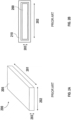
- the neutron detectors shown in FIGS. 1A-2B are exemplary only. The present disclosure is not limited to any particular shape, form factor, or embodiment of neutron detector, and may be utilized with any suitable neutron detector.
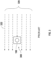
- FIG. 3 is a top-view illustration of the neutron detector 100 of FIG. 1A within a field of neutron flux 320.
- a tube neutron detector 100 is oriented vertically so that the length of the tube is not visible in the illustration.
- the tube neutron detector 100 may be surrounded by a close fit moderator, creating a moderated neutron detector known in the prior art ("prior art detector") 300.
- Neutrons 322 within a field of neutron flux 320 may propagate in relatively straight lines for distances of about 150 meters. Neutrons 322 that propagate in a direction outside of the path of the prior art detector 300 may not impinge upon the tube neutron detector 100 and thus, may not be counted.
- only a very small portion of neutrons 322 within the field of neutron flux 320 may reach the detector 100.
- Embodiments corresponding to FIGS. 4-5 are not encompassed by the wording of the claims but are considered as useful for understanding the invention.
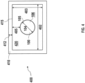
- FIG. 4 is a cross-sectional illustration of a tube form factor moderated neutron sensor (“moderated neutron sensor") 400, in accordance with a first exemplary embodiment of the present disclosure.
- the moderated neutron sensor 400 may include a neutron detector 100 having a first volume.
- a moderating enclosure 410 is positioned around the neutron detector 100 and encloses a second volume.
- the second volume is between 2 and 80 times larger than the first volume.
- the neutron detector (“neutron detector”) 100 may be any type, shape, or form of neutron detector suitable for detecting thermal and epithermal neutrons. Detectors of this type may include gas-proportional detectors, scintillation neutron detectors, semiconductor neutron detectors, and the like.
- the neutron detector 100 may be sized and shaped to detect neutrons over a desired area, within size or weight constraints, or with a desired sensitivity.
- FIG. 4 shows a cross-section of a tube form factor neutron detector 100.
- the volume of the neutron detector 100 may be calculated as discussed relative to FIGS. 1A-1B , above, using the diameter 104 and length of the neutron detector.
- the volume of the neutron detector 100 may be called a first volume.
- a moderating enclosure 410 may be positioned around the neutron detector 100.
- the moderating enclosure 410 may be made from a moderating material capable of interacting with neutrons of a desired energy range.
- the moderating enclosure 410 may be made from a moderating material having a high hydrogen content, such as water, paraffin, HDPE, ultra-high molecular weight plastic (UHMW), or any combination thereof.
- the moderating enclosure 410 may surround and enclose the entire neutron detector 100.
- the thickness 412 of the moderating enclosure 410 may be between 0.5 inches and 2.0 inches. In another example, the thickness 412 of the moderating enclosure 410 may be greater than 2.0 inches.
- the thickness 412 of the moderating enclosure 410 may be about 2.5 inches.
- the moderating enclosure 410 may enclose a volume, called the second volume.
- the second volume may be determined from the interior width 402, interior depth 403, and interior length of the moderating enclosure (not shown due to perspective).
- the interior width 402, interior depth 403, and interior length may be the distance between opposing interior surfaces 415 of the moderating enclosure 410.
- the second volume enclosed by the moderating enclosure 410 may be between 2 and 80 times larger than the first volume occupied by the neutron detector 100.
- the second volume may be between 2 and 20 times larger than the first volume. More particularly, the second volume may be between 5 and 10 times larger than the first volume.
- the ratio of the second volume to the first volume may correlate with an increase in the sensitivity of the moderated neutron sensor 400 up to a maximum value.
- the second volume enclosed by the moderating enclosure 410 may be too large relative to the first volume of the neutron detector 100 to effectively direct neutrons to the neutron detector 100. The neutrons may actually be directed away from the neutron detector 100 due to the geometry of the moderating enclosure 410 at volume ratios larger than 80 times larger.
- the second volume may be larger than the first volume due primarily to a difference between the depth 103 of the neutron detector 100 (shown in FIG. 1A ) and the depth 403 of the moderating enclosure 410.
- the difference between the depth 103 of the neutron detector 100 and the interior depth 403 of the moderating enclosure 410 may be larger than the difference between the length 101 of the neutron detector 100 and the length of the moderating enclosure 410.
- the moderating enclosure 410 may be spaced a greater distance from the neutron detector 100 along the depth direction than along the length direction.
- the depth direction may have a more pronounced effect on the moderated neutron sensor 400's sensitivity than the length direction.
- a moderated neutron sensor 400 with a deeper moderating enclosure 410 may be more sensitive to neutrons than a moderated neutron sensor 400 with a longer moderating enclosure 410.
- This effect may depend on the shapes of the neutron detector 100 and the moderating enclosure 410.
- a tube-shaped neutron detector 100 may detect more neutrons with a deeper or wider moderating enclosure 410, assuming the neutron detector 100 is located centrally within the moderating enclosure 410.
- a sheet-shaped neutron detector 200 (shown in FIG. 2A ) may detect more neutrons with a deeper moderating enclosure 410.
- the neutron detector 100 may be located centrally within the moderating enclosure 410, meaning that the neutron detector 100 is located substantially at and along the center of the interior 420 of the moderating enclosure 410. This may be particularly true when the moderated neutron sensor 400 includes a single neutron detector 100. When the moderated neutron sensor 400 includes two or more neutron detectors 100, the neutron detectors 100 may not be located centrally.
- the moderated neutron sensor 400 may measure neutrons in the 1eV to 2MeV range, including all neutrons between epithermal and fast neutrons. Thus, the moderated neutron sensor 400 may be considered a fast or epithermal neutron sensor.
- the moderated neutron sensors shown in this disclosure may be hydrogen-sensitive neutron sensors, although the disclosure is not so limited. Hydrogen-sensitive neutron sensors may detect neutrons having an energy range of 0-2 MeV, which may include cosmogenic neutrons useful for cosmogenic neutron-based soil moisture measurement.
- the moderating enclosure 410 may generally have a thickness between 0.5 and 2.0 inches, which may allow the hydrogen-sensitive neutron sensor to measure neutrons in the range from 0-2MeV, and particularly in the range of 1eV-2MeV.
- Other types of neutron sensors may be used for environmental neutron monitoring, radioactive waste monitoring, area or perimeter monitoring around nuclear power plants or uranium mines, portal monitoring, and the like.
- a sensor for measuring fast neutrons propagating from nuclear waste may have a moderating enclosure 410 thick enough to thermalize neutrons in the energy band around 5MeV.
- the thickness 412 of the moderating enclosure 410 may be appropriate for its intended application in conjunction with the neutron detector 100.
- the relationship between the neutron detector 100 and the moderating enclosure 410 may be understood as a function of the distance 405 between an exterior surface 105 of the neutron detector 100 and an interior surface 415 of the moderating enclosure 410 ("spaced distance" 405).
- a moderated neutron detector 400 includes a neutron detector 100 having an exterior surface 105.
- a moderating enclosure 410 is positioned around the neutron detector 100.
- the moderating enclosure 410 has an interior surface 415 positioned a spaced distance 405 away from the exterior surface 105 of the neutron detector 100 by at least one half inch.
- the moderating enclosure 410 and the neutron detector 100 may be positioned a spaced distance apart.
- the spaced distance 405 may be at least 0.5 inches. In another example, the spaced distance may be at least 2 inches. In another example the spaced distance may be at least 3 inches.
- the spaced distance 405 may not be constant at every point between the exterior surface 105 of the neutron detector 100 and the interior surface of the moderating enclosure 100.
- the spaced distance 405 may be considered to be the minimum distance between any two points on the exterior surface 105 and interior surface 415. In this case, the minimum distance between any two points on the exterior surface 105 and the interior surface 415 may be at least 0.5 inches.
- the spaced distance 405 may be measured along the length 101 of the neutron detector 100, but not from an end surface 106 of the neutron detector 100.
- the ends at either extreme of the tube may form an end surface 106, depicted in FIG. 4 as a circle.
- the spaced distance 405 may not be measured from the plane of the end surface 106, but may only be considered from the exterior surface 105 in an orthogonal plane.
- the interior 420 between the neutron detector 100 and the moderating enclosure 410 may include anything that is substantially transparent to the passage of neutrons.
- the interior 420 may be a vacuum.
- the interior 420 may be filled with air or another substantially transparent gas.
- the interior 420 may be filled with a substantially transparent liquid or solid. Substantially transparent solids may support the neutron detector 100, holding it in place within the moderating enclosure 410.
- the moderated neutron sensor 400 may include additional electronic components, such as a power source, communications interface, control hardware, and the like.
- the power source may be a battery or solar power.
- the communications interface may allow a user to collect and retrieve neutron data from the moderated neutron detector 400.
- the communications interface may include communications hardware, such as data ports, antennas, and the like, and may be accessed by wired or wireless communication.
- the control hardware may allow a user to operate and troubleshoot the device.
- FIG. 5 is a top-view illustration of the moderated neutron sensor 400 of FIG. 4 within a field of neutron flux 320, in accordance with the first exemplary embodiment of the present disclosure.
- the moderated neutron sensor 400 includes the neutron detector 100 and the moderating enclosure 410.
- the neutrons 322 in the field of neutron flux 320 propagate in a straight line toward and near the moderated neutron sensor 400.
- a greater number of neutrons 322 interact with the moderating enclosure 410 and are directed toward the neutron detector 100.
- Neutrons 324 that would have otherwise missed the neutron detector 100 may now be read by the moderated neutron sensor 400.
- FIG. 6 is a cross-sectional illustration of a sheet form factor moderated neutron sensor ("moderated neutron sensor") 600, in accordance with the presently claimed invention.
- the sheet form factor moderated neutron sensor 600 is generally similar to the tube form factor moderated neutron sensor 400 of FIG. 4 , above.
- the sheet form factor is shown for purposes of illustration.
- the moderated neutron sensor 600 includes a neutron detector 200 having a first volume.
- a moderating enclosure 610 is positioned around the neutron detector 200 and encloses a second volume.
- the second volume is between 2 and 80 times larger than the first volume. In one example, the second volume is between 2 and 20 times larger than the first volume. In another example, the second volume is between 5 and 10 times larger than the first volume.
- the moderating enclosure 610 is positioned around the neutron detector 200 and surrounds and encloses the entire neutron detector 200.
- the thickness 612 of the moderating enclosure 610 may be between about 0.5 inches and 1.5 inches. In another example, the thickness 612 of the moderating enclosure 610 may be greater than 2.0 inches. For example, in applications with higher energy, more monoenergetic neutrons, such as a 5MeV neutron source, the thickness 612 of the moderating enclosure 610 may be about 2.5 inches.
- the moderating enclosure 610 encloses a second volume, which is determined from the interior width 602, interior depth 603, and interior length of the moderating enclosure (not shown due to perspective). The interior width 602, interior depth 603, and interior length is the distance between opposing interior surfaces 615 of the moderating enclosure 610.
- the second volume is larger than the first volume due to a difference between the depth 203 of the neutron detector 200 (shown in FIG. 2A ) and the depth 603 of the moderating enclosure 610.
- the difference between the depth 203 of the neutron detector 200 and the interior depth 603 of the moderating enclosure 610 is larger than the difference between the length 101 of the neutron detector 200 and the length of the moderating enclosure 610.
- the moderating enclosure 610 is spaced a greater distance from the neutron detector 200 along the depth direction than along the length direction.
- the neutron detector 200 may be located centrally within the moderating enclosure 610.
- the relationship between the neutron detector 200 and the moderating enclosure 610 is a function of the distance 605 between an exterior surface 205 of the neutron detector 200 and an interior surface 615 of the moderating enclosure 610 ("spaced distance" 605).
- a moderated neutron detector 600 includes a neutron detector 200 having an exterior surface 205.
- a moderating enclosure 610 is positioned around the neutron detector 200.
- the moderating enclosure 610 has an interior surface 615 positioned a spaced distance 605 away from the exterior surface 205 of the neutron detector 200 by at least one half inch.
- the moderating enclosure 610 and the neutron detector 200 is positioned a spaced distance apart.
- the spaced distance 605 may be at least 0.5 inches. In another example, the spaced distance may be at least 2 inches. In another example the spaced distance may be at least 3 inches.
- the spaced distance 605 may not be constant at every point between the exterior surface 205 of the neutron detector 200 and the interior surface of the moderating enclosure 610.
- the spaced distance 605 is considered to be the minimum distance between any two points on the exterior surface 205 and interior surface 615. In this case, the minimum distance between any two points on the exterior surface 205 and the interior surface 615 may be at least 0.5 inches.
- the spaced distance 605 may be measured along the length 101 of the neutron detector 200, but not from an end surface 206 of the neutron detector 200. In one example, the spaced distance 605 may not be measured from the plane of the end surface 206, but may only be considered from the exterior surface 205 in an orthogonal plane.
- the interior 620 between the neutron detector 200 and the moderating enclosure 610 may include anything that is substantially transparent to the passage of neutrons, as discussed relative to FIG. 4 , above.
- FIG. 7 is an exemplary graph 700 showing neutron sensor sensitivity as a function of moderator depth for a lithium-6 panel detector, in accordance with the first exemplary embodiment of the present disclosure.
- a moderated neutron sensor was constructed according to the disclosure in FIG. 6 , above.
- a Li-6 detector was positioned in a moderating enclosure having about 1 inch thickness. The length and width of the moderating enclosure were fixed during each measurement, but the depth of the moderating enclosure was increased during each measurement. The neutron count was measured for each iteration of the moderating enclosure depth. The depth values used and resultant sensitivity counts are shown in Table 1, below. TABLE 1 - Moderating Enclosure Depth vs. Detector Sensitivity Moderating Enclosure Depth (inches) Sensitivity (counts per second) 8.00 1.89 7.00 1.75 5.50 1.72 4.38 1.60 3.25 1.51 2.63 1.53 2.00 1.48
- the data from the graph 700 in FIG. 7 seems to indicate that, for this type and shape of moderated neutron sensor, a deeper moderating enclosure correlates with an increase in moderated neutron sensor sensitivity. At a depth of 8 inches, the moderated neutron sensor counted about 27% more neutrons per second than the sensor with a moderating enclosure at a depth of 2 inches.
- the moderating enclosure described in FIGS. 4 and 6 was built having interior dimensions of 42"x10"x8" (length x width x depth) and a thickness of 1".
- a number of neutron detectors were sequentially positioned within the moderating enclosure and used to measure neutrons detected per hour.
- the neutron detectors were 2 inch diameter He3 detectors of 12 inch and 40 inch lengths, 2 inch, 3 inch, and 4 inch BF3 detectors of 33 inch lengths, and a 38 inch Li6 panel.
- the neutron detectors were also positioned within prior art close-fit moderators and used to measure neutrons detected per hour under similar conditions.
- multiple detectors were positioned within the moderating enclosure, and measurements were taken. The data is shown in Table 2, below.
- Table 2 shows that each neutron detector saw an increased count over the measurement period when a moderating enclosure was added instead of a close fit moderator.
- the detector count values from Table 2 were then normalized using the detector count values for each neutron detector with a close fit moderator.
- the normalized results are shown in Table 3, below as detector sensitivity vs. moderator size.
- the detector count values in Table 3 are expressed as a ratio of the actual count rate to the count rate of the detectors using close fit moderators.
- the sensitivity for each detector with a close-fit moderator is set to 1, while the sensitivity for each detector with a moderating enclosure is set as a ratio.
- the data from Table 3 shows improvement in sensitivity for each of the detectors in a moderating enclosure.
- the 3"OD x 33" BF3 detector goes from 1 to 1.58, a significant sensitivity enhancement.
- the enhancement is nearly 2.
- the biggest increase going from a close fitted (cylindrical or rectangular) moderator to the moderating enclosure is realized with the 3"OD tube.
- the size of the moderating enclosure (42x12x10) is just such that it best enhances the 3"OD tube. For any given tube diameter, going from a close fit moderator to larger sizes must create a count rate graph that increases at first but which may eventually decrease.
- the 3"OD BF3 tube has the best enhancement, with a volume ratio of 20:1 between detector and moderating enclosure.
- the volume ratios for the 2", 3" and 4" OD detectors are: 40:1, 20:1 and 10:1, respectively.
- the He3 (2"OD x 40") detector has the largest sensitivity enhancement, which is nearly 2. This may be due to the He3 neutron detector itself, which is more sensitive per unit of volume than the other neutron detectors tested. It is worth noting this enhancement. For mobile detectors using He3, larger moderating enclosures may result in a significant sensitivity enhancement, which in turn may result in a much less costly moderated neutron sensor.
- FIG. 8 is a flow chart 800 showing a method for increased neutron detection, in accordance with a second exemplary embodiment of the present disclosure.
- any process descriptions or blocks in flow charts should be understood as representing modules, segments, or steps that include one or more instructions for implementing specific logical functions in the process, and alternate implementations are included within the scope of the present disclosure in which functions may be executed out of order from that shown or discussed, including substantially concurrently or in reverse order, depending on the functionality involved, as would be understood by those reasonably skilled in the art of the present disclosure.
- Step 810 includes positioning a neutron detector within a moderating enclosure, wherein the neutron detector has a first volume, wherein the moderating enclosure encloses a second volume, and wherein the second volume is between 2 and 80 times larger than the first volume.
- the neutron detector (“neutron detector”) may be any neutron detector discussed relative to FIGS. 1A-7 , above.
- the volume of the neutron detector may be the volume occupied by the detector and any tube, sheet, or other structure that holds, contains, or supports the active elements within the neutron detector.
- the moderating enclosure may be any moderating enclosure discussed relative to FIGS. 1A-7 , above.
- the second volume enclosed by the moderating enclosure may be the interior volume determined by the interior length, interior width, and interior depth of the moderating enclosure. In one example, the second volume may be between 2 and 80 times larger than the first volume. In another example, the second volume may be between 2 and 20 times larger than the first volume. In another example, the second volume may be between 5 and 10 times larger than the first volume.
- the second volume is larger than the first volume due to a difference between the depth of the neutron detector and the depth of the moderating enclosure.
- the difference between the depth of the neutron detector and the interior depth of the moderating enclosure is larger than the difference between the length of the neutron detector and the length of the moderating enclosure.
- the moderating enclosure is spaced a greater distance from the neutron detector along the depth direction than along the length direction.
- the spaced distance there is a spaced distance between an exterior surface of the neutron detector and an interior surface of the moderating enclosure.
- the spaced distance creates an interior volume.
- the interior volume may include anything substantially transparent to the passage of neutrons, including a vacuum, gases such as air, liquids, or solid materials.
- the neutron detector may be centrally located within the moderating enclosure.
- the thickness of the moderating enclosure may be between 0.5 and 2.0 inches. In another example, the thickness of the moderating enclosure may be greater than 2.0 inches. For example, in applications with higher energy, more monoenergetic neutrons, such as a 5MeV neutron source, the thickness of the moderating enclosure may be about 2.5 inches.
- Step 820 includes measuring a quantity of neutrons impinging upon the neutron detector, whereby the measured quantity of neutrons is increased by the moderating enclosure directing an increased quantity of neutrons toward the neutron detector.
- measuring a quantity of neutrons may be implemented in a number of ways.
- the moderated neutron sensor which can be considered the neutron detector, moderating enclosure, and associated components, may be positioned above a measurement surface or proximate to a measurement area. The position of the moderated neutron sensor may be located in the path of a field of neutron flux. Neutrons may impinge upon the neutron detector. The moderated neutron sensor may record the quantity of neutrons impinging upon the detector over a desired period of time. This number may be stored in memory, transmitted via a network, or further processed for analysis.
- the moderated neutron sensor may be implemented in a number of forms.
- the moderated neutron sensor may be part of a portal monitor searching for nuclear material passing through an area.
- the moderated neutron sensor may be deployed on a vehicle such as an automobile, airplane, unmanned aerial vehicle, and the like.
- the moderated neutron sensor may be deployed on a tower, tall building, or satellite.
- the measured quantity of neutrons may be increased by the moderating enclosure directing an increased quantity of neutrons toward the neutron detector. This increase may be relative to a bare neutron detector or a neutron detector having a prior art close fit moderator.
- the measured quantity of neutrons may be increased by a factor greater than 1.3.
- the measured quantity of neutrons may be increased by a factor greater than 1.5.
- the measured quantity of neutrons may be increased by a factor greater than 1.9.
- the method may further include any other features, components, or functions disclosed relative to any other figure of this disclosure.
Landscapes
- Life Sciences & Earth Sciences (AREA)
- Health & Medical Sciences (AREA)
- Physics & Mathematics (AREA)
- General Physics & Mathematics (AREA)
- Chemical & Material Sciences (AREA)
- Spectroscopy & Molecular Physics (AREA)
- Molecular Biology (AREA)
- High Energy & Nuclear Physics (AREA)
- Engineering & Computer Science (AREA)
- Immunology (AREA)
- Analytical Chemistry (AREA)
- Biochemistry (AREA)
- General Health & Medical Sciences (AREA)
- Pathology (AREA)
- Medicinal Chemistry (AREA)
- Food Science & Technology (AREA)
- Remote Sensing (AREA)
- Geology (AREA)
- General Life Sciences & Earth Sciences (AREA)
- Environmental & Geological Engineering (AREA)
- Measurement Of Radiation (AREA)
- Analysing Materials By The Use Of Radiation (AREA)
Claims (4)
- Sensor (600) für moderierte Neutronen, der Folgendes umfasst:einen einzelnen plattenförmigen Neutronendetektor (200) mit einem ersten Volumen undein moderierendes Gehäuse (610), das den einzelnen plattenförmigen Neutronendetektor (200) umgibt und umschließt,wobei das moderierende Gehäuse (610) ein zweites Volumen umschließt, wobei das zweite Volumen aus einer Innenbreite (602), einer Innentiefe (603) und einer Innenlänge des moderierenden Gehäuses (610) bestimmt ist,dadurch gekennzeichnet, dass:eine Differenz in Richtung einer Tiefe (203) zwischen dem ersten Volumen und dem zweiten Volumen größer ist als eine Differenz in der Länge (101) zwischen dem ersten Volumen und dem zweiten Volumen, wobei die Richtung der Tiefe (302) orthogonal über eine Stirnfläche des einzelnen plattenförmigen Neutronendetektors (200) gemessen ist, wobei eine zwischen einer Außenfläche (205) des einzelnen plattenförmigen Neutronendetektors (200) und einer Innenfläche (615) des moderierenden Gehäuses (610) gemessene Abstandsstrecke (605) in Richtung der Tiefe (203) größer ist als in einer Längenrichtung und wobei die Abstandsstrecke (605) mindestens 1,27 cm (0,5 Zoll) beträgt,wobei eine Empfindlichkeit des einzelnen plattenförmigen Neutronendetektors (200) vom Maß der Tiefe (203) des moderierenden Gehäuses (610) bezüglich des einzelnen plattenförmigen Neutronendetektors (200) abhängig ist undwobei die Empfindlichkeit des einzelnen plattenförmigen Neutronendetektors (200) mit zunehmendem Maß der Tiefe (203) des moderierenden Gehäuses (610) zunimmt.
- Sensor für moderierte Neutronen nach Anspruch 1, bei dem sich der einzelne plattenförmige Neutronendetektor (200) mittig in dem moderierenden Gehäuse (610) befindet.
- Sensor für moderierte Neutronen nach Anspruch 1 oder 2, bei dem eine Dicke (612) des moderierenden Gehäuses (610) zwischen 1,27 und 5,08 cm (0,5 und 2,0 Zoll) beträgt.
- Sensor für moderierte Neutronen nach Anspruch 1, 2 oder 3, bei dem der einzelne plattenförmige Neutronendetektor (200) ferner einen Helium-3-Detektor (He3-Detektor) umfasst.
Applications Claiming Priority (3)
| Application Number | Priority Date | Filing Date | Title |
|---|---|---|---|
| US201762596315P | 2017-12-08 | 2017-12-08 | |
| EP18885680.1A EP3721214B1 (de) | 2017-12-08 | 2018-12-07 | Moderierter neutronensensor |
| PCT/US2018/064573 WO2019113514A1 (en) | 2017-12-08 | 2018-12-07 | Moderated neutron sensor |
Related Parent Applications (2)
| Application Number | Title | Priority Date | Filing Date |
|---|---|---|---|
| EP18885680.1A Division EP3721214B1 (de) | 2017-12-08 | 2018-12-07 | Moderierter neutronensensor |
| EP18885680.1A Division-Into EP3721214B1 (de) | 2017-12-08 | 2018-12-07 | Moderierter neutronensensor |
Publications (3)
| Publication Number | Publication Date |
|---|---|
| EP4040142A1 EP4040142A1 (de) | 2022-08-10 |
| EP4040142B1 true EP4040142B1 (de) | 2025-02-26 |
| EP4040142C0 EP4040142C0 (de) | 2025-02-26 |
Family
ID=66696061
Family Applications (3)
| Application Number | Title | Priority Date | Filing Date |
|---|---|---|---|
| EP22165845.3A Active EP4040142B1 (de) | 2017-12-08 | 2018-12-07 | Moderierter neutronensensor |
| EP18887019.0A Active EP3721215B1 (de) | 2017-12-08 | 2018-12-07 | Abstands- und richtungsempfindliche kosmogene neutronensensoren |
| EP18885680.1A Active EP3721214B1 (de) | 2017-12-08 | 2018-12-07 | Moderierter neutronensensor |
Family Applications After (2)
| Application Number | Title | Priority Date | Filing Date |
|---|---|---|---|
| EP18887019.0A Active EP3721215B1 (de) | 2017-12-08 | 2018-12-07 | Abstands- und richtungsempfindliche kosmogene neutronensensoren |
| EP18885680.1A Active EP3721214B1 (de) | 2017-12-08 | 2018-12-07 | Moderierter neutronensensor |
Country Status (3)
| Country | Link |
|---|---|
| US (2) | US10564112B2 (de) |
| EP (3) | EP4040142B1 (de) |
| WO (2) | WO2019113514A1 (de) |
Families Citing this family (9)
| Publication number | Priority date | Publication date | Assignee | Title |
|---|---|---|---|---|
| US11249036B2 (en) | 2017-12-08 | 2022-02-15 | Quaesta Instruments, Llc | Distance and direction-sensitive cosmogenic neutron sensors |
| US12259507B2 (en) | 2017-12-08 | 2025-03-25 | Quaesta Instruments, Llc | Distance and direction-sensitive cosmogenic neutron sensors |
| US11474048B2 (en) | 2017-12-08 | 2022-10-18 | Quaesta Instruments, Llc | Distance and direction-sensitive cosmogenic neutron sensors |
| IT201900000076A1 (it) * | 2019-01-04 | 2020-07-04 | Univ Degli Studi Padova | Dispositivo e un procedimento per la misura del contenuto idrico del suolo, della vegetazione e del manto nevoso |
| CN110530901B (zh) * | 2019-09-11 | 2020-09-01 | 中国科学院南京土壤研究所 | 融合宇宙射线中子法和无人机遥感的中小尺度土壤水监测系统及方法 |
| US11927552B2 (en) | 2020-10-12 | 2024-03-12 | Quaesta Instruments, Llc | Systems and methods for cosmogenic neutron sensing moisture detection in agricultural settings |
| EP4001905B1 (de) * | 2020-11-23 | 2025-01-01 | Quaesta Instruments, LLC | Abstands- und richtungsempfindliche kosmogene neutronensensoren |
| US12618785B1 (en) * | 2021-10-25 | 2026-05-05 | Quaesta Instruments, Llc | Systems and methods of cosmic ray sensing of soil moisture for turf grass and crop management |
| EP4239321B1 (de) * | 2022-02-09 | 2026-01-14 | Quaesta Instruments, LLC | Abstands- und richtungssensitive kosmogene neutronensensoren |
Family Cites Families (43)
| Publication number | Priority date | Publication date | Assignee | Title |
|---|---|---|---|---|
| US2928965A (en) | 1954-10-27 | 1960-03-15 | Westinghouse Electric Corp | Neutron detector |
| JPS5513319B2 (de) | 1974-06-15 | 1980-04-08 | ||
| US4463264A (en) | 1982-06-07 | 1984-07-31 | The United States Of America As Represented By The Secretary Of The Navy | Lightweight neutron detector |
| WO1990001158A1 (fr) * | 1988-07-27 | 1990-02-08 | Kazakhsky Gosudarstvenny Universitet Imeni S.M.Kirova | Dispositif de mesure de la teneur en humidite dans le sol et la neige |
| US5321269A (en) * | 1990-04-24 | 1994-06-14 | Hitachi, Ltd. | Neutron individual dose meter, neutron dose rate meter, neutron detector and its method of manufacture |
| US5083029A (en) | 1991-02-04 | 1992-01-21 | Halliburton Company | Measuring water content by neutron thermalization |
| US5502303A (en) | 1994-07-28 | 1996-03-26 | Trustees Of The University Of Pennsylvania | Electronic phantom source for gamma-ray cameras |
| US20010046274A1 (en) * | 2000-04-28 | 2001-11-29 | Craig Richard A. | Method and apparatus for the detection of hydrogenous materials |
| JP3845685B2 (ja) | 2001-07-10 | 2006-11-15 | 独立行政法人 日本原子力研究開発機構 | 放射性廃棄物固体内の核分裂性物質量の非破壊的測定装置 |
| US6924487B2 (en) | 2002-10-01 | 2005-08-02 | Constellation Technology Corporation | Neutron detector |
| CA2528177A1 (en) * | 2003-06-05 | 2004-12-16 | Niton Llc | Neutron and gamma ray monitor |
| US7078705B1 (en) | 2003-09-30 | 2006-07-18 | The Regents Of The University Of California | Neutron and gamma detector using an ionization chamber with an integrated body and moderator |
| US7233007B2 (en) * | 2004-03-01 | 2007-06-19 | Nova Scientific, Inc. | Radiation detectors and methods of detecting radiation |
| WO2006110159A2 (en) | 2004-07-29 | 2006-10-19 | Kansas State University Research Foundation | Micro neutron detectors |
| FR2883074B1 (fr) * | 2005-03-10 | 2007-06-08 | Centre Nat Rech Scient | Systeme de detection bidimensionnelle pour rayonnement neutrons |
| JP4576368B2 (ja) | 2006-10-16 | 2010-11-04 | 三菱重工業株式会社 | 中性子モデレータ及び中性子照射方法並びに危険物質検出装置 |
| US7514694B2 (en) | 2007-06-19 | 2009-04-07 | Material Innovations, Inc. | Neutron detector |
| GB0722430D0 (en) | 2007-11-15 | 2007-12-27 | Health Prot Agency | Radiation detection |
| DE102008050731A1 (de) | 2008-10-08 | 2010-04-15 | Bundesrepublik Deutschland, vertr.d.d. Bundesministerium für Wirtschaft und Technologie, d.vertr.d.d. Präsidenten der Physikalisch-Technischen Bundesanstalt | Neutronendosimeter |
| US9081100B1 (en) | 2011-10-27 | 2015-07-14 | The Curator Of The University Of Missouri | Apparatus and method for determination of one or more free neutron characteristics |
| US9958561B2 (en) | 2009-08-20 | 2018-05-01 | The Curators Of The University Of Missouri | Apparatus and method for the determination of one or more neutron source characteristics |
| US9817138B2 (en) | 2009-08-27 | 2017-11-14 | Douglas S. McGregor | Gas-filled neutron detectors and imaging system and array of such detectors |
| EP2293114B1 (de) | 2009-09-02 | 2017-09-06 | 3833364 Canada Inc. (operating as DETEC) | Neutronenenergiespektrometer |
| US8796634B2 (en) | 2011-03-01 | 2014-08-05 | Ut-Battelle, Llc | High efficiency proportional neutron detector with solid liner internal structures |
| GB201107076D0 (en) | 2011-04-27 | 2011-06-08 | Finphys Oy | Neutron detector |
| GB2492999A (en) | 2011-07-20 | 2013-01-23 | Univ Central Lancashire | Neutron detector |
| CN103176203A (zh) | 2011-12-22 | 2013-06-26 | 同方威视技术股份有限公司 | 一种探测器以及使用该探测器同时探测伽马射线和中子射线的方法 |
| CN103185894B (zh) | 2011-12-28 | 2016-08-03 | 同方威视技术股份有限公司 | 一种快中子探测器 |
| CN103513267B (zh) * | 2012-06-21 | 2016-05-11 | 同方威视技术股份有限公司 | 含硼气膜快中子探测器 |
| US20140158895A1 (en) | 2012-07-05 | 2014-06-12 | Los Alamos National Security, Llc | Pulse-shape discrimination of neutrons using drift tubes |
| DE102012108766A1 (de) | 2012-09-18 | 2014-03-20 | CDT Cascade Detector Technologies GmbH | Neutronendetektoreinheit sowie Neutronendetektoranordnung |
| US9329303B2 (en) | 2012-10-04 | 2016-05-03 | Baker Hughes Incorporated | Single detector detection and characterization of thermal and epithermal neutrons from an earth formation |
| GB2511107A (en) | 2013-02-25 | 2014-08-27 | Symetrica Ltd | Neutron detector and method for detecting neutrons |
| US20150241577A1 (en) | 2013-12-19 | 2015-08-27 | Schlumberger Technology Corporation | Combined Epithermal And Thermal Neutron Detector And Its Application To Well Logging Instruments |
| WO2015148924A1 (en) | 2014-03-27 | 2015-10-01 | Lnd, Incorporated | Neutron detector using proportional counters |
| GB2526109A (en) | 2014-05-14 | 2015-11-18 | Symetrica Ltd | Neutron detection |
| CN110083221A (zh) | 2014-06-09 | 2019-08-02 | 威盛电子股份有限公司 | 电子装置及音频播放方法 |
| US10302780B2 (en) | 2014-10-17 | 2019-05-28 | Silverside Detectors Inc. | Fissile neutron detector |
| US9645262B2 (en) | 2014-11-26 | 2017-05-09 | Lawrence Livermore National Security, Llc | Capacitance reduction for pillar structured devices |
| US9778392B2 (en) | 2015-01-22 | 2017-10-03 | The United States Of America, As Represented By The Secretary Of The Navy | 3Helium gas proportional counter |
| CA2901709A1 (en) | 2015-08-27 | 2017-02-27 | Bubble Technology Industries Inc. | An accurate light-weight broad-energy neutron remmeter and use thereof |
| US9910170B1 (en) | 2016-06-15 | 2018-03-06 | Honeywell Federal Manufacturing & Technologies, Llc | Neutron emission detector |
| US10281600B2 (en) | 2017-04-13 | 2019-05-07 | Jefferson Science Associates, Llc | Neutron detector and dose rate meter using beryllium-loaded materials |
-
2018
- 2018-12-07 WO PCT/US2018/064573 patent/WO2019113514A1/en not_active Ceased
- 2018-12-07 WO PCT/US2018/064548 patent/WO2019113496A1/en not_active Ceased
- 2018-12-07 EP EP22165845.3A patent/EP4040142B1/de active Active
- 2018-12-07 US US16/213,812 patent/US10564112B2/en active Active
- 2018-12-07 US US16/213,741 patent/US10845318B2/en active Active
- 2018-12-07 EP EP18887019.0A patent/EP3721215B1/de active Active
- 2018-12-07 EP EP18885680.1A patent/EP3721214B1/de active Active
Also Published As
| Publication number | Publication date |
|---|---|
| WO2019113514A1 (en) | 2019-06-13 |
| EP3721215B1 (de) | 2025-12-03 |
| US20190179041A1 (en) | 2019-06-13 |
| EP3721214B1 (de) | 2023-11-01 |
| EP3721214C0 (de) | 2023-11-01 |
| EP3721214A1 (de) | 2020-10-14 |
| US10845318B2 (en) | 2020-11-24 |
| US10564112B2 (en) | 2020-02-18 |
| EP3721214A4 (de) | 2021-08-25 |
| WO2019113496A1 (en) | 2019-06-13 |
| EP3721215C0 (de) | 2025-12-03 |
| EP4040142A1 (de) | 2022-08-10 |
| EP4040142C0 (de) | 2025-02-26 |
| EP3721215A1 (de) | 2020-10-14 |
| EP3721215A4 (de) | 2021-10-13 |
| US20190178818A1 (en) | 2019-06-13 |
Similar Documents
| Publication | Publication Date | Title |
|---|---|---|
| US10564112B2 (en) | Moderated neutron sensor | |
| Peerani et al. | Testing on novel neutron detectors as alternative to 3He for security applications | |
| JP6016835B2 (ja) | 放射線検出 | |
| Grasty et al. | Fields of view of airborne gamma-ray detectors | |
| CN102928867B (zh) | 补偿型中子剂量仪 | |
| WO1991017462A1 (en) | Neutron exposure dosimeter for individual use, neutron dose rate meter, neutron detector and method of producing them | |
| JPWO1991017462A1 (ja) | 中性子検出装置 | |
| CN103616713B (zh) | 探测器及探测系统 | |
| US20180299570A1 (en) | Neutron detector and dose rate meter using beryllium-loaded materials | |
| KR102505224B1 (ko) | 질화 붕소 나노튜브 중성자 검출장치 | |
| US3602713A (en) | Passive moisture meter | |
| Tang et al. | Simulated minimum detectable activity concentration (MDAC) for a real-time UAV airborne radioactivity monitoring system with HPGe and LaBr3 detectors | |
| CN109154673B (zh) | 中子检测装置的操作状态验证方法 | |
| US7701336B1 (en) | Detection of nuclear materials hidden inside cargo shipments by using sensor fusion technique | |
| Joseph et al. | Geometry correction in efficiency of a sodium iodide (Thallium Activated), NaI (Tl) detector | |
| CN107664765A (zh) | 一种氡子体板卡累积吸附式土壤氡快速测量装置 | |
| US7599463B2 (en) | Remote sensing device to detect materials of varying atomic numbers | |
| US3098944A (en) | Gamma proportional counter containing high z gas and low z moderator | |
| JP2001027674A (ja) | 中性子線量率計 | |
| CN113504559A (zh) | 一种强流脉冲宽能谱中子剂量率监测装置 | |
| Nelson et al. | Results and potential applications of handheld, midsized, and large-area low-cost Li foil MWPCS | |
| RU214394U1 (ru) | Устройство детектирования нейтронов | |
| Aplin et al. | Compact cosmic ray detector for unattended atmospheric ionization monitoring | |
| Jashank et al. | Development of radon gas sensor to monitor the precursors of earthquake | |
| Niese | Measurements of fast neutrons above ground and in 47 m depth with a 3 He proportional counter |
Legal Events
| Date | Code | Title | Description |
|---|---|---|---|
| PUAI | Public reference made under article 153(3) epc to a published international application that has entered the european phase |
Free format text: ORIGINAL CODE: 0009012 |
|
| STAA | Information on the status of an ep patent application or granted ep patent |
Free format text: STATUS: THE APPLICATION HAS BEEN PUBLISHED |
|
| AC | Divisional application: reference to earlier application |
Ref document number: 3721214 Country of ref document: EP Kind code of ref document: P |
|
| AK | Designated contracting states |
Kind code of ref document: A1 Designated state(s): AL AT BE BG CH CY CZ DE DK EE ES FI FR GB GR HR HU IE IS IT LI LT LU LV MC MK MT NL NO PL PT RO RS SE SI SK SM TR |
|
| STAA | Information on the status of an ep patent application or granted ep patent |
Free format text: STATUS: REQUEST FOR EXAMINATION WAS MADE |
|
| 17P | Request for examination filed |
Effective date: 20230209 |
|
| RBV | Designated contracting states (corrected) |
Designated state(s): AL AT BE BG CH CY CZ DE DK EE ES FI FR GB GR HR HU IE IS IT LI LT LU LV MC MK MT NL NO PL PT RO RS SE SI SK SM TR |
|
| GRAP | Despatch of communication of intention to grant a patent |
Free format text: ORIGINAL CODE: EPIDOSNIGR1 |
|
| STAA | Information on the status of an ep patent application or granted ep patent |
Free format text: STATUS: GRANT OF PATENT IS INTENDED |
|
| INTG | Intention to grant announced |
Effective date: 20240930 |
|
| GRAS | Grant fee paid |
Free format text: ORIGINAL CODE: EPIDOSNIGR3 |
|
| GRAA | (expected) grant |
Free format text: ORIGINAL CODE: 0009210 |
|
| STAA | Information on the status of an ep patent application or granted ep patent |
Free format text: STATUS: THE PATENT HAS BEEN GRANTED |
|
| AC | Divisional application: reference to earlier application |
Ref document number: 3721214 Country of ref document: EP Kind code of ref document: P |
|
| AK | Designated contracting states |
Kind code of ref document: B1 Designated state(s): AL AT BE BG CH CY CZ DE DK EE ES FI FR GB GR HR HU IE IS IT LI LT LU LV MC MK MT NL NO PL PT RO RS SE SI SK SM TR |
|
| REG | Reference to a national code |
Ref country code: GB Ref legal event code: FG4D |
|
| REG | Reference to a national code |
Ref country code: CH Ref legal event code: EP |
|
| REG | Reference to a national code |
Ref country code: DE Ref legal event code: R096 Ref document number: 602018079739 Country of ref document: DE |
|
| REG | Reference to a national code |
Ref country code: IE Ref legal event code: FG4D |
|
| U01 | Request for unitary effect filed |
Effective date: 20250310 |
|
| U07 | Unitary effect registered |
Designated state(s): AT BE BG DE DK EE FI FR IT LT LU LV MT NL PT RO SE SI Effective date: 20250317 |
|
| PG25 | Lapsed in a contracting state [announced via postgrant information from national office to epo] |
Ref country code: RS Free format text: LAPSE BECAUSE OF FAILURE TO SUBMIT A TRANSLATION OF THE DESCRIPTION OR TO PAY THE FEE WITHIN THE PRESCRIBED TIME-LIMIT Effective date: 20250526 |
|
| PG25 | Lapsed in a contracting state [announced via postgrant information from national office to epo] |
Ref country code: PL Free format text: LAPSE BECAUSE OF FAILURE TO SUBMIT A TRANSLATION OF THE DESCRIPTION OR TO PAY THE FEE WITHIN THE PRESCRIBED TIME-LIMIT Effective date: 20250226 |
|
| PG25 | Lapsed in a contracting state [announced via postgrant information from national office to epo] |
Ref country code: ES Free format text: LAPSE BECAUSE OF FAILURE TO SUBMIT A TRANSLATION OF THE DESCRIPTION OR TO PAY THE FEE WITHIN THE PRESCRIBED TIME-LIMIT Effective date: 20250226 |
|
| PG25 | Lapsed in a contracting state [announced via postgrant information from national office to epo] |
Ref country code: NO Free format text: LAPSE BECAUSE OF FAILURE TO SUBMIT A TRANSLATION OF THE DESCRIPTION OR TO PAY THE FEE WITHIN THE PRESCRIBED TIME-LIMIT Effective date: 20250526 Ref country code: IS Free format text: LAPSE BECAUSE OF FAILURE TO SUBMIT A TRANSLATION OF THE DESCRIPTION OR TO PAY THE FEE WITHIN THE PRESCRIBED TIME-LIMIT Effective date: 20250626 |
|
| PG25 | Lapsed in a contracting state [announced via postgrant information from national office to epo] |
Ref country code: HR Free format text: LAPSE BECAUSE OF FAILURE TO SUBMIT A TRANSLATION OF THE DESCRIPTION OR TO PAY THE FEE WITHIN THE PRESCRIBED TIME-LIMIT Effective date: 20250226 |
|
| PG25 | Lapsed in a contracting state [announced via postgrant information from national office to epo] |
Ref country code: GR Free format text: LAPSE BECAUSE OF FAILURE TO SUBMIT A TRANSLATION OF THE DESCRIPTION OR TO PAY THE FEE WITHIN THE PRESCRIBED TIME-LIMIT Effective date: 20250527 |
|
| PG25 | Lapsed in a contracting state [announced via postgrant information from national office to epo] |
Ref country code: SM Free format text: LAPSE BECAUSE OF FAILURE TO SUBMIT A TRANSLATION OF THE DESCRIPTION OR TO PAY THE FEE WITHIN THE PRESCRIBED TIME-LIMIT Effective date: 20250226 |
|
| PG25 | Lapsed in a contracting state [announced via postgrant information from national office to epo] |
Ref country code: CZ Free format text: LAPSE BECAUSE OF FAILURE TO SUBMIT A TRANSLATION OF THE DESCRIPTION OR TO PAY THE FEE WITHIN THE PRESCRIBED TIME-LIMIT Effective date: 20250226 |
|
| PG25 | Lapsed in a contracting state [announced via postgrant information from national office to epo] |
Ref country code: SK Free format text: LAPSE BECAUSE OF FAILURE TO SUBMIT A TRANSLATION OF THE DESCRIPTION OR TO PAY THE FEE WITHIN THE PRESCRIBED TIME-LIMIT Effective date: 20250226 |
|
| PLBE | No opposition filed within time limit |
Free format text: ORIGINAL CODE: 0009261 |
|
| STAA | Information on the status of an ep patent application or granted ep patent |
Free format text: STATUS: NO OPPOSITION FILED WITHIN TIME LIMIT |
|
| 26N | No opposition filed |
Effective date: 20251127 |
|
| U20 | Renewal fee for the european patent with unitary effect paid |
Year of fee payment: 8 Effective date: 20251229 |