EP4037987B1 - Biologisch abbaubares siplid und verfahren zu seiner herstellung - Google Patents
Biologisch abbaubares siplid und verfahren zu seiner herstellung Download PDFInfo
- Publication number
- EP4037987B1 EP4037987B1 EP20789293.6A EP20789293A EP4037987B1 EP 4037987 B1 EP4037987 B1 EP 4037987B1 EP 20789293 A EP20789293 A EP 20789293A EP 4037987 B1 EP4037987 B1 EP 4037987B1
- Authority
- EP
- European Patent Office
- Prior art keywords
- siplid
- side wall
- edge
- biodegradable
- drinking
- Prior art date
- Legal status (The legal status is an assumption and is not a legal conclusion. Google has not performed a legal analysis and makes no representation as to the accuracy of the status listed.)
- Active
Links
Images


Classifications
-
- B—PERFORMING OPERATIONS; TRANSPORTING
- B65—CONVEYING; PACKING; STORING; HANDLING THIN OR FILAMENTARY MATERIAL
- B65D—CONTAINERS FOR STORAGE OR TRANSPORT OF ARTICLES OR MATERIALS, e.g. BAGS, BARRELS, BOTTLES, BOXES, CANS, CARTONS, CRATES, DRUMS, JARS, TANKS, HOPPERS, FORWARDING CONTAINERS; ACCESSORIES, CLOSURES, OR FITTINGS THEREFOR; PACKAGING ELEMENTS; PACKAGES
- B65D43/00—Lids or covers for rigid or semi-rigid containers
- B65D43/02—Removable lids or covers
- B65D43/0202—Removable lids or covers without integral tamper element
- B65D43/0204—Removable lids or covers without integral tamper element secured by snapping over beads or projections
- B65D43/0212—Removable lids or covers without integral tamper element secured by snapping over beads or projections only on the outside, or a part turned to the outside, of the mouth
-
- B—PERFORMING OPERATIONS; TRANSPORTING
- B65—CONVEYING; PACKING; STORING; HANDLING THIN OR FILAMENTARY MATERIAL
- B65D—CONTAINERS FOR STORAGE OR TRANSPORT OF ARTICLES OR MATERIALS, e.g. BAGS, BARRELS, BOTTLES, BOXES, CANS, CARTONS, CRATES, DRUMS, JARS, TANKS, HOPPERS, FORWARDING CONTAINERS; ACCESSORIES, CLOSURES, OR FITTINGS THEREFOR; PACKAGING ELEMENTS; PACKAGES
- B65D47/00—Closures with filling and discharging, or with discharging, devices
- B65D47/04—Closures with discharging devices other than pumps
- B65D47/06—Closures with discharging devices other than pumps with pouring spouts or tubes; with discharge nozzles or passages
- B65D47/08—Closures with discharging devices other than pumps with pouring spouts or tubes; with discharge nozzles or passages having articulated or hinged closures
- B65D47/0804—Closures with discharging devices other than pumps with pouring spouts or tubes; with discharge nozzles or passages having articulated or hinged closures integrally formed with the base element provided with the spout or discharge passage
- B65D47/0833—Hinges without elastic bias
- B65D47/0847—Hinges without elastic bias located within a flat surface of the base element
-
- B—PERFORMING OPERATIONS; TRANSPORTING
- B65—CONVEYING; PACKING; STORING; HANDLING THIN OR FILAMENTARY MATERIAL
- B65D—CONTAINERS FOR STORAGE OR TRANSPORT OF ARTICLES OR MATERIALS, e.g. BAGS, BARRELS, BOTTLES, BOXES, CANS, CARTONS, CRATES, DRUMS, JARS, TANKS, HOPPERS, FORWARDING CONTAINERS; ACCESSORIES, CLOSURES, OR FITTINGS THEREFOR; PACKAGING ELEMENTS; PACKAGES
- B65D65/00—Wrappers or flexible covers; Packaging materials of special type or form
- B65D65/38—Packaging materials of special type or form
- B65D65/46—Applications of disintegrable, dissolvable or edible materials
- B65D65/466—Bio- or photodegradable packaging materials
-
- B—PERFORMING OPERATIONS; TRANSPORTING
- B65—CONVEYING; PACKING; STORING; HANDLING THIN OR FILAMENTARY MATERIAL
- B65D—CONTAINERS FOR STORAGE OR TRANSPORT OF ARTICLES OR MATERIALS, e.g. BAGS, BARRELS, BOTTLES, BOXES, CANS, CARTONS, CRATES, DRUMS, JARS, TANKS, HOPPERS, FORWARDING CONTAINERS; ACCESSORIES, CLOSURES, OR FITTINGS THEREFOR; PACKAGING ELEMENTS; PACKAGES
- B65D2543/00—Lids or covers essentially for box-like containers
- B65D2543/00009—Details of lids or covers for rigid or semi-rigid containers
- B65D2543/00018—Overall construction of the lid
- B65D2543/00046—Drinking-through lids
-
- B—PERFORMING OPERATIONS; TRANSPORTING
- B65—CONVEYING; PACKING; STORING; HANDLING THIN OR FILAMENTARY MATERIAL
- B65D—CONTAINERS FOR STORAGE OR TRANSPORT OF ARTICLES OR MATERIALS, e.g. BAGS, BARRELS, BOTTLES, BOXES, CANS, CARTONS, CRATES, DRUMS, JARS, TANKS, HOPPERS, FORWARDING CONTAINERS; ACCESSORIES, CLOSURES, OR FITTINGS THEREFOR; PACKAGING ELEMENTS; PACKAGES
- B65D2543/00—Lids or covers essentially for box-like containers
- B65D2543/00009—Details of lids or covers for rigid or semi-rigid containers
- B65D2543/00018—Overall construction of the lid
- B65D2543/00064—Shape of the outer periphery
- B65D2543/00074—Shape of the outer periphery curved
- B65D2543/00092—Shape of the outer periphery curved circular
-
- B—PERFORMING OPERATIONS; TRANSPORTING
- B65—CONVEYING; PACKING; STORING; HANDLING THIN OR FILAMENTARY MATERIAL
- B65D—CONTAINERS FOR STORAGE OR TRANSPORT OF ARTICLES OR MATERIALS, e.g. BAGS, BARRELS, BOTTLES, BOXES, CANS, CARTONS, CRATES, DRUMS, JARS, TANKS, HOPPERS, FORWARDING CONTAINERS; ACCESSORIES, CLOSURES, OR FITTINGS THEREFOR; PACKAGING ELEMENTS; PACKAGES
- B65D2543/00—Lids or covers essentially for box-like containers
- B65D2543/00009—Details of lids or covers for rigid or semi-rigid containers
- B65D2543/00018—Overall construction of the lid
- B65D2543/00259—Materials used
- B65D2543/00268—Paper
-
- B—PERFORMING OPERATIONS; TRANSPORTING
- B65—CONVEYING; PACKING; STORING; HANDLING THIN OR FILAMENTARY MATERIAL
- B65D—CONTAINERS FOR STORAGE OR TRANSPORT OF ARTICLES OR MATERIALS, e.g. BAGS, BARRELS, BOTTLES, BOXES, CANS, CARTONS, CRATES, DRUMS, JARS, TANKS, HOPPERS, FORWARDING CONTAINERS; ACCESSORIES, CLOSURES, OR FITTINGS THEREFOR; PACKAGING ELEMENTS; PACKAGES
- B65D2543/00—Lids or covers essentially for box-like containers
- B65D2543/00009—Details of lids or covers for rigid or semi-rigid containers
- B65D2543/00444—Contact between the container and the lid
- B65D2543/00481—Contact between the container and the lid on the inside or the outside of the container
- B65D2543/00537—Contact between the container and the lid on the inside or the outside of the container on the outside, or a part turned to the outside of the mouth of the container
-
- B—PERFORMING OPERATIONS; TRANSPORTING
- B65—CONVEYING; PACKING; STORING; HANDLING THIN OR FILAMENTARY MATERIAL
- B65D—CONTAINERS FOR STORAGE OR TRANSPORT OF ARTICLES OR MATERIALS, e.g. BAGS, BARRELS, BOTTLES, BOXES, CANS, CARTONS, CRATES, DRUMS, JARS, TANKS, HOPPERS, FORWARDING CONTAINERS; ACCESSORIES, CLOSURES, OR FITTINGS THEREFOR; PACKAGING ELEMENTS; PACKAGES
- B65D2543/00—Lids or covers essentially for box-like containers
- B65D2543/00009—Details of lids or covers for rigid or semi-rigid containers
- B65D2543/00444—Contact between the container and the lid
- B65D2543/00592—Snapping means
- B65D2543/00712—Snapping means on the lid
- B65D2543/00722—Profiles
- B65D2543/00731—Groove or hollow bead
-
- B—PERFORMING OPERATIONS; TRANSPORTING
- B65—CONVEYING; PACKING; STORING; HANDLING THIN OR FILAMENTARY MATERIAL
- B65D—CONTAINERS FOR STORAGE OR TRANSPORT OF ARTICLES OR MATERIALS, e.g. BAGS, BARRELS, BOTTLES, BOXES, CANS, CARTONS, CRATES, DRUMS, JARS, TANKS, HOPPERS, FORWARDING CONTAINERS; ACCESSORIES, CLOSURES, OR FITTINGS THEREFOR; PACKAGING ELEMENTS; PACKAGES
- B65D2543/00—Lids or covers essentially for box-like containers
- B65D2543/00009—Details of lids or covers for rigid or semi-rigid containers
- B65D2543/00444—Contact between the container and the lid
- B65D2543/00592—Snapping means
- B65D2543/00712—Snapping means on the lid
- B65D2543/00722—Profiles
- B65D2543/0074—Massive bead
-
- Y—GENERAL TAGGING OF NEW TECHNOLOGICAL DEVELOPMENTS; GENERAL TAGGING OF CROSS-SECTIONAL TECHNOLOGIES SPANNING OVER SEVERAL SECTIONS OF THE IPC; TECHNICAL SUBJECTS COVERED BY FORMER USPC CROSS-REFERENCE ART COLLECTIONS [XRACs] AND DIGESTS
- Y02—TECHNOLOGIES OR APPLICATIONS FOR MITIGATION OR ADAPTATION AGAINST CLIMATE CHANGE
- Y02W—CLIMATE CHANGE MITIGATION TECHNOLOGIES RELATED TO WASTEWATER TREATMENT OR WASTE MANAGEMENT
- Y02W90/00—Enabling technologies or technologies with a potential or indirect contribution to greenhouse gas [GHG] emissions mitigation
- Y02W90/10—Bio-packaging, e.g. packing containers made from renewable resources or bio-plastics
Definitions
- the invention relates to a biodegradable siplid, a drinking cup with such a siplid and a method for manufacturing such siplids.
- the EU has expressed the intention to reduce the production and use of single-use plastic food packaging products to zero in 2021.
- a known major source of single-use plastic waste are liquid cups and the accompanying (single-use) siplids, such as siplids for travel cups used for soft drinks or hot drinks such as coffee.
- Billions of single-use plastic siplids are produced each year, many of which end up in the environment as waste.
- biodegradable siplids which include marine degradable or compostable siplids, were developed. Such biodegradable siplids are known from practice.
- US 2013/0248481 A1 discloses a lid made of fibrous material according to the preamble of claim 1.
- a disadvantage of the known biodegradable siplids is fluid uptake in the structure of the biodegradable siplid, which is due to the structure and material of the siplids. Such fluid uptake decreases structural integrity of the siplid at the location of the fluid uptake. In addition, the fluid uptake, in case of coloured drinks, leads to discolouration of the siplid which has a negative impact on consumer satisfaction.
- the invention provides a biodegradable siplid from moulded pulp according to claim 1.
- An advantage of reducing the thickness and/or increasing the density of the siplid in the compressed areas is that it results in a reduction of the fluid uptake in these areas due to an increased resistance against fluid intrusion.
- the reduction of the thickness and/or increase of the density may be performed for example by compressing the number of compressed areas with a higher pressure than the remaining parts of the siplid. It may also be performed by applying an additional compression step to compress the second areas.
- the decreased thickness and/or increased density of the compressed areas is compared to a thickness and/or density of the area that is lower respectively higher as compared to the average thickness and/or density of the siplid.
- the higher pressure and/or additional compression step is applied/performed at the compressed areas having the same or an increased amount of material per area as compared to the average amount of material per area for the siplid.
- Another advantage of the siplid according to the invention is that the rigidity of the compressed areas is increased compared to the rigidity of the other parts of the siplid.
- Yet another advantage of the siplid according to the invention is that the strength of the compressed areas is (significantly) increased compared to the uncompressed areas. This provides a more robust siplid, which provides the advantage that the siplid is more resistant to damage and thus can more easily be transported.
- a density increase of 25% results in a surprisingly high increase of compression strength (in N) of more than 35% and for some embodiments more than 50% or even more than 100%.
- the number of compressed areas in the siplid according to the invention are preferably manufactured from substantially the same base material.
- the base material is provided with the compressed areas during manufacturing of the siplid and does not require a significantly different base material.
- the difference in thickness and/or density of the number of compressed areas is preferably a result of the manufacturing. It is noted that in most cases, the reduction in thickness will substantially automatically result in an increase of the density of that area, because the same amount of material is contained in a smaller volume (thus increasing density).
- the biodegradable siplid from moulded pulp and/or moulded fiber comprises:
- a reduction in the thickness may be in the range of 10% - 90%, preferably may be in the range of 25% - 75% and more preferably may be in the range of 40% - 60% and/or wherein an increase in the density may be in the range of 30% - 70%, preferably may be in the range of 35% - 65% and more preferably may be in the range of 40% - 45%.
- the increase in density is preferably in the aforementioned ranges in relation to the reduction in thickness.
- the reduction in fluid uptake of the siplid depends on the amount of reduction and/or the amount of increase of the density, with a smaller thickness and/or a higher density leading to increased resistance against fluid uptake (and thus lower fluid uptake during use).
- the reduced thickness and/or increased density also increase the rigidity of the compressed areas, which may not always be preferred. The abovementioned ranges achieve a good balance between the increase in fluid uptake resistance and the rigidity.
- the biodegradable siplid further comprises a sealing rim that is provided in the side wall and that is placeable over an edge of a cup to provide a sealing connection with said cup.
- An advantage of the sealing rim is that it obviates or at least significantly reduces leakage of fluid between the siplid and a drinking cup to which the siplid is attached.
- the effect of the sealing rim as such increases the sealing effect that is already achieved by the use of the one or more clamping elements.
- the number of compressed areas comprise moulded pulp and/or moulded fibres that are glassified.
- An advantage of providing glazed fibers or pulp is that it provides enhanced protection against intrusion/uptake of fluids and moisture due to a reduced fluid uptake.
- moisture or amounts of beverage enter the fiber layers of the siplid through the (rough) edges that are in contact with the siplid and/or via (prolonged) contact of the fluid with the siplid. This occurs for example at or near the drinking opening and/or the clamping elements and/or the sealing rim.
- 'coloured' fluids such as coffee or coke
- this provides coloured stains in the siplid, which reduce the attractiveness of the siplid during use.
- the siplid locally obtains a more dense structure, which obviates or at least significantly reduces the amount of uptake of external fluids/moisture and, additionally and/or alternatively reduces colour staining of the siplid.
- the glazed fibers also provide a smoother finish, which is esthetically attractive to customers, especially near the drinking opening.
- the smoother finish especially near the drinking opening edge, also improves the drinking experience of the customer by providing a smoother flow and a reduced risk of paper cuts.
- the smoother finish is that, due to a lower variation in surface height, the sealing rim and/or clamping elements can be manufactured to a more specific measurement.
- the smoother edge allows the siplid to be manufactured to more precise specifications. This in turn leads to a better sealing and/or clamping of the siplid on a drinking cup edge.
- the number of compressed areas comprise the sealing rim and/or one or more of the clamping elements.
- the compressed areas which have a reduced thickness and/or an increased density
- the sealing rim and/or the clamping elements are the sealing rim and/or the clamping elements, because these areas are prone to prolonged exposure to fluid contained in the drinking cup.
- the increased protection against fluid uptake therefore results in a longer lifetime by virtue of reduced loss of integrity, as well as in reduced discolouration in case 'coloured' fluid, such as coffee of coke, is held in the drinking cup.
- Another advantage is that the number of compressed areas, especially when these are the sealing rim and/or one ore more of the clamping elements, increase the rigidity of the sealing rim and/or the clamping areas and therewith the clamping and/or sealing properties of the siplid.
- the one or more clamping elements are formed by one or more projections that extend from the side wall radially inwards towards a central axis that extends substantially perpendicular to the top wall, wherein the one or more projections are placeable over the edge of a cup and against a cup side wall.
- clamping elements are that the siplid can easily and preferably releasable be connected with a drinking cup.
- the clamping may for example be achieved by providing a number of clamping elements in the side wall that together lock the drinking cup edge to the siplid, such it is not easily disengaged.
- the one or more projections can also be replaced by providing one or more indentations in the side wall in which the edge of a cup is placeable. This construction has similar effects and advantages as the use of the abovementioned projections.
- the side wall comprises an annular rim that extends radially outwards in a second direction that is substantially perpendicular to the central axis and the first direction, wherein the annular rim is provided with an annular projection that extends parallel to central axis in the first direction such that the annular projection comprises the sealing rim.
- An advantage of providing an annular rim that is provided with a sealing rim is that it achieves the effect of both sealing the drinking edge cup with the siplid as well as that can be configured to cooperate with the one or more clamping elements to clamp the siplid to the drinking cup.
- the side wall comprises a first side wall section that extends over a predetermined length, and an upper rim section that extends from a radially inner edge that is connected to the first side wall section towards a radially outer edge, and a lower rim section that extends from the radially outer edge towards a lower rim edge, and an end side wall section that extends from the lower rim section towards an end side wall edge, wherein the lower rim section comprises the one or more clamping elements, wherein the upper rim section is provided with the sealing rim, and wherein the clamping elements and the sealing rim cooperate to form a drinking cup edge holding space in which the edge of a drinking cup is placeable and clampable such that the edge of the drinking cup is preferably releasably lockable in the drinking cup edge holding space.
- the abovementioned embodiment provides an advantage in that it provides a further increased clamping force by the cooperation between the sealing rim and the one or more clamping elements. Moreover, the specific shape as described in this embodiment also provides a well distinguishable drinking cup edge opening in which the drinking cup edge is placeable. This directs users of the siplid to the way in which the siplid is to be used and/or applied to a drinking cup.
- the siplid comprises a drinking opening in the top wall and/or the side wall of the siplid, wherein the drinking opening has a drinking opening edge that extends at least partially along a circumference of the drinking opening.
- the siplid can easily be used during travel, for example when travelling in a car, because it obviates the need to remove the siplid when a sip is taken from the beverage in the drinking cup.
- the drinking opening edge is one of the number of compressed areas.
- An advantage of providing the drinking opening as one of the compressed areas, thus in which the drinking opening edge has a reduced thickness and/or an increased density than for example a respective part of the top wall and/or the side wall at a distance from the drinking opening circumference, is that the reduced thickness provides improved protection against fluid uptake of the fibers or pulp. This is due to the higher density of the drinking edge and/or the reduced thickness, yet is additionally also due to the reduced surface area in the opening that can contact the fluid during drinking. As a result, stains in the siplid are substantially avoided. In addition, the migration of (some) components from the drink or fluid to the fibres of the material is also substantially prevented, which prevents loss of taste by selective uptake in the siplid.
- a further advantage of providing a reduced thickness and/or increased density to the drinking opening edge, for example by providing additional pressure to the edge, is that a smoother edge is achieved, which is esthetically attractive to customers.
- the smoother edge also improves the drinking experience of the customer by providing a smoother flow and a reduced risk of paper cuts.
- An even further advantage of the reduced thickness and/or increased density is a reduced risk of fibre rub off, i.e. the risk of fibres releasing from the drinking opening into the drink due to the more solid structure formed by the compressed drinking opening.
- a subset of the number of the clamping elements that is positioned in the side wall near the drinking opening may have a decreased thickness and/or an increased density compared to the number of compressed areas.
- An advantage of providing clamping elements near the drinking opening with a decreased thickness, which is smaller than the thickness of the other compressed areas, and/or with an increased density is that an increased clamping (strength) is achieved near the drinking opening, which is the side of the siplid that is exposed to the highest force during drinking. As a result, the risk of accidental release of the siplid during drinking is reduced.
- Another advantage is that the area near the drinking opening has an increased wall strength, which reduces the risk of the side wall buckling under the weight of the fluid and/or the pressure from a users mouth against the siplid. This leads to a decreased risk of accidental release and/or leakage due to (local) buckling of the siplid wall.
- forming the subset of the number of clamping elements is performed in a compression step that is separate from the drying and moulding step in which the siplid is formed.
- the number of compressed areas may comprise a first number of compressed areas and a second number of compressed areas, wherein a thickness of the second number of compressed areas is smaller than a thickness of the first number of compressed areas, and/or wherein a density of the second number of compressed areas is higher than a density of the first number of compressed areas, and wherein the second number of compressed areas comprises clamping elements that are positioned in the side wall near and/or adjacent to the drinking opening.
- An advantage of providing clamping elements near the drinking opening with a decreased thickness, which is smaller than the thickness of the other compressed areas, and/or with an increased density is that an increased clamping (strength) is achieved near the drinking opening, which is the side of the siplid that is exposed to the highest force during drinking. As a result, the risk of accidental release of the siplid during drinking is reduced.
- Another advantage is that the area near the drinking opening has an increased wall strength, which reduces the risk of the side wall buckling under the weight of the fluid and/or the pressure from a users mouth against the siplid. This leads to a decreased risk of accidental release and/or leakage due to (local) buckling of the siplid wall.
- the clamping element comprises a single clamping ring that extends over substantially the entire circumference of the side wall, wherein the clamping ring is a compressed area of the number of compressed areas, and wherein a part of the clamping ring near the drinking opening has a increased thickness and/or increased density compared to the remaining part of the clamping ring.
- An advantage of a clamping ring is that the siplid has a high clamping force over the entire circumference of the cup to which it is attached.
- the clamping force is, by providing near the drinking opening a part of the clamping ring with an increased thickness and/or increased density, advantageously even increased near the drinking opening at which the greatest force is exerted on the siplid.
- an increased clamping (strength) is achieved near the drinking opening, which reduces the risk of accidental release of the siplid during drinking.
- the drinking opening is provided in the top wall of the siplid, and wherein the top wall is provided with a closure tab that is configured for resealably closing the drinking opening.
- closure tab is useable to prevent heat losses from hot drinks and/or prevent heating of cold drinks when the user is not drinking the beverage.
- a closure tab improves the user experience by preserving the beverage (either hot or cold) through shielding it from heating up or cooling down of a respective cold beverage or hot beverage.
- the closure tab may be a separate closure tab that is not connected to the siplid or a closure tab that is (integrally) connected to the siplid (and is preferably integrally formed therewith).
- the closure tab is hingedly connected to the top wall, and wherein the hinge comprises a hinge area that is formed by pressing a part of the drinking opening circumference to a smaller thickness than an area directly adjacent to the hinge area, and wherein the closure tab is at least partially formed from the upper wall.
- the drinking opening may also be provided with a hinge that allows the drinking opening to be at least partially reclosed.
- a hinged closure is advantageously formed by pressing a part of the circumference with a higher pressure, such that it has a reduced thickness compared to other parts of the surface. As a consequence, the closure will, upon exerting pressure by a customer, fold around the pressed hinge, thus forming a hinged closure.
- a hinged closure has the advantage that it provides additional conservation of heat (or cold) in the drink contained in the drinking cup to which the siplid is attached.
- the top wall comprises a number of indentations and/or projections.
- An advantage of the siplid according to the invention is that it can, in a single moulding step, be provided with any number of projections and/or indentations in the top wall. This provides the advantage that commercial messages and/or brand name/forms can be applied to the top wall.
- an indentation of the number of indentations is configured for at least partially receiving the closure tab, and wherein, when the closure tab is in an open position, the drinking opening is accessible for a user.
- the top wall is provided with an indentation that is positioned adjacent the hinge and that is configured for receiving the closure tab. This allows a user to open the closure tab, fix it in place in the opening in the top wall to prevent it from interfering the with drinking action of the user, and subsequently be released from the opening to close the drinking opening again.
- the indentation that is configured for at least partially receiving the closure tab comprises a number of ribs that preferably extend parallel to each other along a side wall of the indentation downwards from the top wall.
- the drinking opening in the siplid is preferably provided with a hinged closure tab and an association indentation in the top wall of the siplid that is configured to receive the closure tab when it is in an open position.
- This has the advantage that the drinking opening remains free and easily accessible by a user. It has however been found that the closure tab, when moved into the associated indentation, often is released and moves back to the closing position when the siplid is tilted. This for example occurs when a user tilts the drinking cup with siplid during drinking.
- An advantage of the ribs provided in the indentation is that the closure tab is subjected to increased friction, therewith reducing or even obviating the risk of accidental release during use.
- the ribs extend parallel to each other from the top wall downwardly into the indentation. More preferably, it has been found that the ribs are most effective when positioned at a wall opposite the wall of the indentation near the hinged connection. In other words, the ribs extend on the side wall that is positioned furthest away from the hinge.
- the number of ribs preferably is in the range of 2 - 8 and more preferably in the range of 3 - 5. Furthermore, the ribs, when viewed along the indentation side wall, have a width that is in the range of 0.2 - 2.0 mm, and preferably is in the range of 0.5 - 1.5 mm, and more preferably is in the range of 1.2 - 1.5 mm, and most preferably is around 1.4 mm.
- the ribs when viewed from the indentation wall inwards to the open space of the indentation, have a depth in the range of 0.1 - 1.4 mm, more preferably in the range of 0.4 - 1.0 mm and more preferably in the range of 0.6 - 0.8 mm.
- the composition of the siplid comprises an AKD.
- An advantage of adding an AKD is that it provides an increased resistance against moisture, which increase lifetime of the siplid during use.
- siplids are exposed to a relatively high amount of moisture, such as moisture that arises from hot drinks as well as from the drinks themselves during drinking.
- the siplid should be provided such that it remains stiff and operational for a longer period of time during use, for example up to 2 hours. This can be achieved by providing siplids that comprise the abovementioned mixture.
- the siplid comprises an amount of a biodegradable aliphatic polyester, and an inner contact surface that contacts the fluid during use preferably comprises a cellulose-based laminate layer.
- the biodegradable aliphatic polyester may comprise an amount of one or more of PBS, PHB, PHA, PCL, PLA, PGA, PHBH and PHBV.
- the use of biodegradable aliphatic polyester is combined with the use of further additives or substances that aim at improving or achieving specific properties of the packaging unit.
- the biodegradable aliphatic polyester comprises an amount of polybutylene succinate (PBS).
- PBS is one of the biodegradable aliphatic polyesters.
- PBS can also be referred to as polytetramethylene succinate.
- PBS decomposes naturally into water, CO2 and biomass.
- the use of PBS as a compostable material contributes to providing a sustainable product.
- the use of PBS is possible in food-contact applications including food packaging units from a moulded pulp material.
- An advantage of the use of PBS is that the decomposition rate of PBS is much higher as compared to other agents or components such as PLA (including variations thereof such as PLLA, PDLA and PLDLLA, for example).
- the water uptake of the moulded pulp and/or fiber material of the siplid and, specifically the compressed areas is less than 25%, preferably less than 20%, and more preferably less than 10% when submerged in water for a period of 30 minutes.
- An advantage of a reduced water uptake by the siplid is that the structural integrity of the siplid remains intact for a longer period of time.
- Another advantage of the reduced water uptake is that the siplid according to the invention is less prone to fouling, especially fouling by uptake of coloured fluids, such as coffee, coke and/or other coloured drinks, which fouling would reduce the visual attractiveness of the siplid.
- the reduced water uptake according to the invention may be achieved by a high amount of compression during the moulding step, which preferably leads to glazing of the moulded pulp and/or moulded fibers, yet may according to the invention also be achieved by adding additives.
- a Cobb-value of the siplid and, specifically the compressed areas is less than 75 g/m 2 , preferably less than 50 g/m 2 and most preferably less than 25 g/m 2 .
- the aforementioned Cobb-value according to the invention may be achieved by a high amount of compression during the moulding step, which preferably leads to glazing of the moulded pulp and/or moulded fibers, yet may according to the invention also be achieved by adding additives as aforementioned.
- the one or more clamping elements are positioned along a circumferential length of the side wall, wherein the one or more clamping elements together extend over at least one third of the circumferential length, preferably over around 50% of the circumferential length and most preferably over around 75% of the circumferential length of the side wall.
- the one or more clamping elements together extend over at least a third of the circumferential length of the siplid, an improved clamping and sealing of the siplid on the drinking cup edge is achieved. It is preferred that the one or more clamping elements extend over 50% or even 75% of the circumferential length in order to achieve an even further improvement in clamping and sealing of the siplid on the drinking cup edge.
- biodegradable material to manufacture the biodegradable siplids according to the invention.
- biodegradable material has to be prepared in order to be usable for manufacturing siplids, whereas in other cases the biodegradable material can be used without any preprocessing.
- the siplids according to the invention may be manufactured from biomass material of plant or marine origin.
- the siplid according to the invention may for example advantageously be manufactured by applying the method for for manufacturing a moulded fiber product from a biomass material of plant origin as disclosed in patent application WO2016/167648 from the same applicant, which is incorporated here by reference.
- An advantage of using the method disclosed in WO2016/167648 for manufacturing a siplid according to the invention is that the siplid from a biomass material of plant origin improves the flexibility of possible raw materials used for such products.
- the use of biomass of plant origin improves the natural feel for the consumer.
- the sustainability of the siplid according to the invention that is manufactured with the method according to WO2016/167648 is further enhanced.
- a sheet of moulded pulp and/or moulded fibre is preferably foreseen, having a thickness and density that is substantially equal over an entire sheet surface, wherein the sheet has a substantially square or perpendicular shape having longitudinal sides and transverse sides and a number of mould positions, wherein each mould position is configured to be moulded into a siplid according to the invention.
- the sheet comprises a base material that, before being subjected to the manufacturing of the siplids therefrom, has a substantially equal thickness and density over the entire surface of said sheet. It is only during the manufacturing step that the sheet, more specifically the siplids moulded therefrom, are provided with the compressed areas.
- the invention also relates to a drinking cup, preferably a biodegradable drinking cup, provided with a siplid according to the claims invention.
- the drinking cup according to the invention provides similar advantages and effects as the siplid and the sheet according to the invention.
- the method according to the invention provides similar advantages and effects as the siplid, the sheet and the drinking cup according to the invention.
- the step of applying a number of compressed areas comprises applying an increased pressure to the number of compressed areas during the compressing and drying step to provide a decreased thickness and/or an increased density, or comprises compressing the number of compressed areas in a separate compression step to provide a decreased thickness and/or an increased density.
- the method comprises compressing a subset of the number of compressed areas such that the subset has a decreased thickness and/or an increased density, wherein the subset of the number of compressed areas comprises clamping elements that are positioned near and/or adjacent to the drinking opening.
- the step of compressing a subset of the number of compressed areas comprises compressing the subset of the number of compressed areas in a separate compression step to provide a decreased thickness and/or an increased density compared to the subset of the number of compressed areas.
- siplid 258 comprises top wall 260 that extends radially outwards from central axis CA in a second direction X and a third direction Y towards top wall edge 262 that delineates top wall 260.
- Top wall edge 262 is connected to side wall 264, and more specifically to first side wall section 266 that extends, when viewed in first direction Z along and under an angle ⁇ with central axis CA, from top wall edge 262 to radially inner edge 268 of annular ring 270.
- Annular ring 270 includes upper rim section 272 that extends, when viewed from central axis CA, radially outward in second direction X from radially inner edge 268 towards radially outer edge 274.
- annular ring 270 includes lower rim section 276 that substantially in first direction Z from radially outer edge 274 towards lower rim edge 278.
- Lower rim edge 278 in turn is connected to end side wall section 280 of side wall 264 that extends from lower rim edge 278 to end side wall edge 282.
- Upper rim section 272 is provided with an annular groove that extends between radially inner edge 268 and radially outer edge 274 and that, when viewed from top wall 260 in first direction Z towards end side wall edge 282, is positioned lower than both radial edges 268, 274 such that it forms a projection on an inside of siplid 258 in the form of sealing rim 284.
- Lower rim section 276 is provided with clamping edge or undercut 286 that extends, when viewed from central axis CA in second direction X radially inwardly with respect to radially outer edge 274 and lower rim edge 278, to form clamping element or undercut 286.
- clamping element of clamping edge 286 is annular ring 286.
- closure tab 294 may be slightly distorted upon contact with ribs 295. This serves to further increase the fixation force on closure tab 294.
- siplid 258 in this example is provided with a number of indentations and projections 298 that represent commercial signs or embossings.
- the number of such indentations and projections 298, as well as the depth, form and position thereof may be varied in different siplids 258.
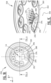
- siplid 358 comprises top wall 360 that extends radially outwards from central axis CA in a second direction X and in third direction Y towards top wall edge 362 that delineates top wall 360.
- Top wall edge 362 is connected to side wall 364, and more specifically to first side wall section 366 that extends, when viewed in first direction Z along and under an angle ⁇ with central axis CA, from top wall edge 362 to radially inner edge 368 of annular ring 370.
- Annular ring 370 includes upper rim section 372 that extends, when viewed from central axis CA, radially outward in second direction X and/or third direction Y from radially inner edge 368 towards radially outer edge 374.
- annular ring 370 includes lower rim section 376 that substantially in first direction Z from radially outer edge 374 towards lower rim edge 378.
- Lower rim edge 378 in turn is connected to end side wall section 380 of side wall 364 that extends from lower rim edge 378 to end side wall edge 382.
- Upper rim section 372 is provided with an annular groove that extends between radially inner edge 368 and radially outer edge 374 and that, when viewed from top wall 360 in first direction Z towards end side wall edge 382, is positioned lower than both radial edges 368, 374 such that it forms a projection on an inside of siplid 358 in the form of sealing rim 384.
- Lower rim section 376 is provided with clamping edge 386 that extends, when viewed from central axis CA in second direction X radially inwardly with respect to radially outer edge 374 and lower rim edge 378, to form clamping element 386.
- clamping element or clamping edge 386 is annular ring 386.
- Siplid 358 further includes drinking opening 388 that is positioned in top wall 360.
- the circumference of the drinking opening 388 comprises drinking opening edge 390.
- Drinking opening 388 has drinking opening edge 390 that has a thickness that is less than a thickness of the other parts of top wall 360. This may for example be provided by means of compressing the drinking opening edge with a higher pressure than is applied to other parts of top wall 360.
- drinking opening edge 390 is glazed such that it has reduced fluid uptake (and thus increased fluid resistance).
- siplid 358 in this example is provided with indentation 398.
- the number of such indentations and projections 398, as well as the depth, form and position thereof may be varied in different siplids 358.
Landscapes
- Engineering & Computer Science (AREA)
- Mechanical Engineering (AREA)
- Life Sciences & Earth Sciences (AREA)
- Biodiversity & Conservation Biology (AREA)
- Table Devices Or Equipment (AREA)
- Closures For Containers (AREA)
Claims (15)
- Biologisch abbaubarer Schlürfdeckel (258,358) aus geformtem Zellstoff und/oder geformter Faser, umfassend:- eine obere Wand (260,360), die einen Rand (262,362) der oberen Wand aufweist;- eine Seitenwand (264,364), die im Wesentlichen entlang des gesamten Rands der oberen Wand mit der oberen Wand derart verbunden ist, dass die Seitenwand die obere Wand abgrenzt; und- ein oder mehrere Klemmelemente (286,386), die in der Seitenwand positioniert sind und die konfiguriert sind, um den Schlürfdeckel über einen Rand eines Bechers zu klemmen und in Klemmverbindung mit einer Seitenwand des Bechers zu stehen;wobei der Schlürfdeckel eine Anzahl komprimierter Bereiche umfasst, die eine verringerte Dicke und/oder eine erhöhte Dichte aufweisen,der Schlürfdeckel ferner umfassend eine Trinköffnung (288,388) in der oberen Wand und/oder der Seitenwand des Schlürfdeckels, wobei die Trinköffnung einen Trinköffnungsrand (290,390) aufweist, der sich mindestens teilweise entlang eines Umfangs der Trinköffnung erstreckt,dadurch gekennzeichnet, dass der Trinköffnungsrand ein komprimierter Bereich ist.
- Biologisch abbaubarer Schlürfdeckel nach Anspruch 1, wobei eine Reduzierung der Dicke und/oder die Erhöhung der Dichte im Bereich von 10 %-90 %, vorzugsweise im Bereich von 25 %-75 % und mehr bevorzugt im Bereich von 40 %-60 % liegt und/oder wobei eine Erhöhung der Dichte im Bereich von 30 %-70 %, vorzugsweise im Bereich von 35 %-65 % und mehr bevorzugt im Bereich von 40 %-45 % liegt.
- Biologisch abbaubarer Schlürfdeckel nach Anspruch 1 oder 2, ferner umfassend eine Dichtungskante (284, 384), die in der Seitenwand bereitgestellt ist und die über einen Rand eines Bechers platzierbar ist, um eine Dichtungsverbindung mit dem Becher bereitzustellen.
- Biologisch abbaubarer Schlürfdeckel nach einem der Ansprüche 1 bis 3, wobei die Anzahl komprimierter Bereiche geformten Zellstoff und/oder geformte Fasern umfasst, die glasiert sind, und/oder wobei die Anzahl komprimierter Bereiche die Dichtungskante (284, 384) und/oder ein oder mehrere der Klemmelemente (286, 386) umfasst.
- Biologisch abbaubarer Schlürfdeckel nach einem der vorstehenden Ansprüche, wobei das eine oder die mehreren Klemmelemente (286, 386) einen oder mehrere Vorsprünge umfassen, die sich von der Seitenwand (264, 364) radial nach innen in Richtung einer Mittelachse (CA) erstrecken, die sich im Wesentlichen senkrecht zu der oberen Wand (260, 360) erstreckt,
wobei der eine oder die mehreren Vorsprünge über den Rand eines Bechers und gegen eine Becherseitenwand platzierbar sind, und/oder wobei das eine oder die mehreren Klemmelemente entlang einer Umfangslänge der Seitenwand positioniert sind, wobei sich das eine oder die mehreren Klemmelemente zusammen über mindestens ein Drittel der Umfangslänge, vorzugsweise über etwa 50 % der Umfangslänge und am meisten bevorzugt über etwa 75 % der Umfangslänge der Seitenwand erstrecken. - Biologisch abbaubarer Schlürfdeckel nach einem der Ansprüche 3 bis 5, wobei die Seitenwand (264, 364) eine ringförmige Kante (270,370) umfasst, die sich radial nach außen in eine zweite Richtung erstreckt, die im Wesentlichen senkrecht zu der Mittelachse (CA) ist, die sich in eine erste Richtung erstreckt, wobei die ringförmige Kante mit einem ringförmigen Vorsprung bereitgestellt ist, der sich parallel zu der Mittelachse in die erste Richtung derart erstreckt, dass der ringförmige Vorsprung die Dichtungskante (284, 384) umfasst, und/oder wobei die Seitenwand (264, 364) umfasst:- einen ersten Seitenwandabschnitt, der sich über eine zuvor bestimmte Länge erstreckt;- einen oberen Kantenabschnitt (272,372), der sich von einen radial inneren Rand (268,368), der mit dem ersten Seitenwandabschnitt verbunden ist, in Richtung eines radial äußeren Rands (274,374) erstreckt;- einen unteren Kantenabschnitt (276,376), der sich im Wesentlichen von dem radial äußeren Rand in Richtung eines Rands der unteren Kante erstreckt; und- einen Endseitenwandabschnitt, der sich von dem unteren Kantenabschnitt in Richtung eines Endseitenwandrands erstreckt;wobei der untere Kantenabschnitt das eine oder die mehreren Klemmelemente (286, 386) umfasst,wobei der obere Kantenabschnitt mit der Dichtungskante bereitgestellt ist, und wobei die Klemmelemente und die Dichtungskante zusammenwirken, um einen Trinkbecherrandhalteraum auszubilden, in den der Rand eines Trinkbechers derart platzierbar und klemmbar ist, dass der Rand des Trinkbechers in dem Trinkbecherrandhalteraum lösbar verriegelbar ist.
- Biologisch abbaubarer Schlürfdeckel nach einem der Ansprüche 1 bis 6, wobei eine Teilmenge der Anzahl der Klemmelemente (286, 386), die in der Seitenwand (264, 364) in der Nähe der Trinköffnung (288, 388) positioniert ist, vorzugsweise eine verringerte Dicke und/oder eine erhöhte Dichte im Vergleich zu der Anzahl komprimierter Bereiche aufweist, oder wobei das Klemmelement vorzugsweise einen einzelnen Klemmring umfasst, der sich im Wesentlichen über den gesamten Umfang der Seitenwand erstreckt, wobei der Klemmring ein komprimierter Bereich der Anzahl komprimierter Bereiche ist, und wobei ein Teil des Klemmrings in der Nähe der Trinköffnung eine erhöhte Dicke und/oder erhöhte Dichte im Vergleich zu dem verbleibenden Teil des Klemmrings aufweist.
- Biologisch abbaubarer Schlürfdeckel nach einem der Ansprüche 1 bis 7, wobei die Trinköffnung (288, 388) in der oberen Wand (260, 360) des Schlürfdeckels bereitgestellt ist und wobei die obere Wand mit einer Verschlusslasche (294) bereitgestellt ist, die zum wiederverschließbaren Verschließen der Trinköffnung konfiguriert ist.
- Biologisch abbaubarer Schlürfdeckel nach Anspruch 8, wobei die Verschlusslasche (294) mit der oberen Wand (260, 360) scharnierartig verbunden ist, und wobei das Scharnier (292,392) einen Scharnierbereich umfasst, der durch Drücken eines Teils des Trinköffnungsumfangs auf eine geringere Dicke als ein Bereich ausgebildet wird, der an den Scharnierbereich direkt angrenzt, und wobei die Verschlusslasche (294) mindestens teilweise aus der oberen Wand (260, 360) ausgebildet ist.
- Biologisch abbaubarer Schlürfdeckel nach einem der vorstehenden Ansprüche, wobei die obere Wand (260, 360) eine Anzahl von Vertiefungen und/oder Vorsprüngen (298,398) umfasst.
- Biologisch abbaubarer Schlürfdeckel nach Anspruch 10, wenn abhängig von Anspruch 9, wobei eine Vertiefung der Anzahl von Vertiefungen (298, 398) zum mindestens teilweisen Aufnehmen der Verschlusslasche (294) konfiguriert ist, und wobei die Trinköffnung (288, 388) für einen Benutzer zugänglich ist, wenn sich die Verschlusslasche in einer offenen Position befindet.
- Biologisch abbaubarer Schlürfdeckel nach Anspruch 11, wobei die Vertiefung, die zum mindestens teilweisen Aufnehmen der Verschlusslasche konfiguriert ist, eine Anzahl von Rippen (295,395) umfasst, die sich vorzugsweise parallel zueinander entlang einer Seitenwand der Vertiefung von der oberen Wand (260, 360) nach unten erstrecken.
- Trinkbecher, vorzugsweise ein biologisch abbaubarer Trinkbecher, der mit einem biologisch abbaubaren Schlürfdeckel (258,358) nach einem der Ansprüche 1 bis 12 bereitgestellt ist.
- Verfahren zum Herstellen eines biologisch abbaubaren Schlürfdeckels (258,358) nach einem der Ansprüche 1 bis 12, das Verfahren umfassend:- Bereitstellen von geformtem Zellstoff und/oder geformten Fasern;- Komprimieren und Trocknen des geformten Zellstoffs und/oder der geformten Faser in einer Form, um einen oder mehrere Schlürfdeckel (258, 358) auszubilden;wobei das Verfahren ferner ein Anbringen einer Anzahl komprimierter Bereiche, die eine verringerte Dicke und/oder eine erhöhte Dichte aufweisen, in jedem Schlürfdeckel umfasst.
- Verfahren nach Anspruch 14, wobei der Schritt des Anbringens einer Anzahl komprimierter Bereiche umfasst:- Anbringen eines erhöhten Drucks auf die Anzahl komprimierter Bereiche während des Komprimierungs- und Trocknungsschritts, um eine verringerte Dicke und/oder eine erhöhte Dichte bereitzustellen; oder- Komprimieren der Anzahl komprimierter Bereiche in einem separaten Komprimierungsschritt, um eine verringerte Dicke und/oder eine erhöhte Dichte zu erreichen, und/oderwobei das Verfahren das Komprimieren einer Teilmenge der Anzahl komprimierter Bereiche derart umfasst, dass die Teilmenge eine verringerte Dicke und/oder eine erhöhte Dichte aufweist, wobei die Teilmenge der Anzahl komprimierter Bereiche Klemmelemente umfasst, die in der Nähe und/oder angrenzend an die Trinköffnung positioniert sind.
Applications Claiming Priority (2)
| Application Number | Priority Date | Filing Date | Title |
|---|---|---|---|
| NL2023969A NL2023969B1 (en) | 2019-10-04 | 2019-10-04 | Biodegradable siplid and method for manufacturing such siplid |
| PCT/NL2020/050611 WO2021066654A1 (en) | 2019-10-04 | 2020-10-02 | Biodegradable siplid and method for manufacturing such siplid |
Publications (3)
| Publication Number | Publication Date |
|---|---|
| EP4037987A1 EP4037987A1 (de) | 2022-08-10 |
| EP4037987B1 true EP4037987B1 (de) | 2025-05-07 |
| EP4037987C0 EP4037987C0 (de) | 2025-05-07 |
Family
ID=68343429
Family Applications (1)
| Application Number | Title | Priority Date | Filing Date |
|---|---|---|---|
| EP20789293.6A Active EP4037987B1 (de) | 2019-10-04 | 2020-10-02 | Biologisch abbaubares siplid und verfahren zu seiner herstellung |
Country Status (6)
| Country | Link |
|---|---|
| EP (1) | EP4037987B1 (de) |
| AU (1) | AU2020361351B2 (de) |
| CA (1) | CA3152927A1 (de) |
| ES (1) | ES3034202T3 (de) |
| NL (1) | NL2023969B1 (de) |
| WO (1) | WO2021066654A1 (de) |
Family Cites Families (6)
| Publication number | Priority date | Publication date | Assignee | Title |
|---|---|---|---|---|
| DE102010062194A1 (de) * | 2010-11-30 | 2012-05-31 | Huhtamäki Oyj | Deckel aus Faserwerkstoff |
| WO2014031880A1 (en) * | 2012-08-22 | 2014-02-27 | Meadwestvaco Corporation | Paper-based container lids |
| DE102013218866A1 (de) * | 2013-09-19 | 2015-03-19 | Huhtamäki Oyj | Trinkbehälterdeckel mit geneigter Deckelfläche |
| ITRM20130196U1 (it) * | 2013-11-16 | 2015-05-17 | Seda Suisse A G | Coperchio richiudibile |
| WO2015130992A1 (en) * | 2014-02-28 | 2015-09-03 | Biovation Ii, Llc | Biocidal sachet for food safety |
| WO2016167648A1 (en) | 2015-04-13 | 2016-10-20 | Huhtamaki Molded Fiber Technology B.V. | Method for manufacturing a moulded fiber product, such as an egg packaging, from a biomass material of plant origin, and such moulded fiber product |
-
2019
- 2019-10-04 NL NL2023969A patent/NL2023969B1/en active
-
2020
- 2020-10-02 WO PCT/NL2020/050611 patent/WO2021066654A1/en not_active Ceased
- 2020-10-02 CA CA3152927A patent/CA3152927A1/en active Pending
- 2020-10-02 ES ES20789293T patent/ES3034202T3/es active Active
- 2020-10-02 EP EP20789293.6A patent/EP4037987B1/de active Active
- 2020-10-02 AU AU2020361351A patent/AU2020361351B2/en active Active
Also Published As
| Publication number | Publication date |
|---|---|
| EP4037987A1 (de) | 2022-08-10 |
| ES3034202T3 (en) | 2025-08-13 |
| CA3152927A1 (en) | 2021-04-08 |
| AU2020361351B2 (en) | 2025-07-10 |
| EP4037987C0 (de) | 2025-05-07 |
| AU2020361351A1 (en) | 2022-05-19 |
| WO2021066654A1 (en) | 2021-04-08 |
| NL2023969B1 (en) | 2021-04-13 |
Similar Documents
| Publication | Publication Date | Title |
|---|---|---|
| CN112262082B (zh) | 来自具有基于纤维素的层压层的模制的纸浆材料的可生物降解的且可堆肥的食品包装单元以及用于制造这样的食品包装单元的方法 | |
| AU2023282229B2 (en) | Method for manufacturing a 3-dimensional shaped product from a fluff pulp material and such product | |
| EP2757194B1 (de) | Zellstoffgeformter Deckel mit nicht vernetzten Innen- und Außenflächen und Verfahren zu seiner Herstellung | |
| US6420689B1 (en) | Disposable, microwaveable containers having suitable food contact compatible olfactory properties and process for their manufacture | |
| ES2905477T3 (es) | Unidad de embalaje de un material de pulpa moldeada con capa de laminado removible y método para fabricar tal unidad de embalaje | |
| US20110278300A1 (en) | Moulded fiber lid | |
| CN120793374A (zh) | 具有层压的多层件的由模制浆料或绒毛浆料制成的可生物降解和可堆肥的食物包装单元及制造这种食物包装单元的方法 | |
| US20110132791A1 (en) | Packaging unit | |
| US12187500B2 (en) | Siplid for a container having a twisting effect, and method for manufacturing such siplid | |
| CA2899097A1 (en) | Biodegradable drink pod | |
| EP4037987B1 (de) | Biologisch abbaubares siplid und verfahren zu seiner herstellung | |
| GB2057337A (en) | Contoured molded pulp container with polyester liner | |
| WO2011152703A1 (en) | Moulded fiber lid | |
| CA3002448C (en) | Insulated paper cups, lids, and containers | |
| JP4231567B2 (ja) | 包装用容器 | |
| KR20250081850A (ko) | 셀룰로오스-기반 재료의 시트로부터 형상화된 퇴비화 가능 포드 | |
| EP4624660A1 (de) | Verfahren zur herstellung einer verpackungseinheit aus einem formbaren zellstoffmaterial, mit solch einem verfahren hergestellte verpackungseinheit und stapel daraus | |
| JP2005198677A (ja) | 合成樹脂製弁当箱 | |
| KR20250160121A (ko) | 기능성 종이 제품 | |
| US20050184029A1 (en) | Food box with thin wooden structure | |
| US779244A (en) | Vessel-lining. |
Legal Events
| Date | Code | Title | Description |
|---|---|---|---|
| STAA | Information on the status of an ep patent application or granted ep patent |
Free format text: STATUS: UNKNOWN |
|
| STAA | Information on the status of an ep patent application or granted ep patent |
Free format text: STATUS: THE INTERNATIONAL PUBLICATION HAS BEEN MADE |
|
| PUAI | Public reference made under article 153(3) epc to a published international application that has entered the european phase |
Free format text: ORIGINAL CODE: 0009012 |
|
| STAA | Information on the status of an ep patent application or granted ep patent |
Free format text: STATUS: REQUEST FOR EXAMINATION WAS MADE |
|
| 17P | Request for examination filed |
Effective date: 20220425 |
|
| AK | Designated contracting states |
Kind code of ref document: A1 Designated state(s): AL AT BE BG CH CY CZ DE DK EE ES FI FR GB GR HR HU IE IS IT LI LT LU LV MC MK MT NL NO PL PT RO RS SE SI SK SM TR |
|
| DAV | Request for validation of the european patent (deleted) | ||
| DAX | Request for extension of the european patent (deleted) | ||
| GRAP | Despatch of communication of intention to grant a patent |
Free format text: ORIGINAL CODE: EPIDOSNIGR1 |
|
| STAA | Information on the status of an ep patent application or granted ep patent |
Free format text: STATUS: GRANT OF PATENT IS INTENDED |
|
| INTG | Intention to grant announced |
Effective date: 20250122 |
|
| GRAS | Grant fee paid |
Free format text: ORIGINAL CODE: EPIDOSNIGR3 |
|
| GRAA | (expected) grant |
Free format text: ORIGINAL CODE: 0009210 |
|
| STAA | Information on the status of an ep patent application or granted ep patent |
Free format text: STATUS: THE PATENT HAS BEEN GRANTED |
|
| AK | Designated contracting states |
Kind code of ref document: B1 Designated state(s): AL AT BE BG CH CY CZ DE DK EE ES FI FR GB GR HR HU IE IS IT LI LT LU LV MC MK MT NL NO PL PT RO RS SE SI SK SM TR |
|
| REG | Reference to a national code |
Ref country code: GB Ref legal event code: FG4D |
|
| REG | Reference to a national code |
Ref country code: CH Ref legal event code: EP |
|
| REG | Reference to a national code |
Ref country code: DE Ref legal event code: R096 Ref document number: 602020050943 Country of ref document: DE |
|
| REG | Reference to a national code |
Ref country code: IE Ref legal event code: FG4D |
|
| U01 | Request for unitary effect filed |
Effective date: 20250603 |
|
| U07 | Unitary effect registered |
Designated state(s): AT BE BG DE DK EE FI FR IT LT LU LV MT NL PT RO SE SI Effective date: 20250610 |
|
| REG | Reference to a national code |
Ref country code: ES Ref legal event code: FG2A Ref document number: 3034202 Country of ref document: ES Kind code of ref document: T3 Effective date: 20250813 |
|
| PG25 | Lapsed in a contracting state [announced via postgrant information from national office to epo] |
Ref country code: NO Free format text: LAPSE BECAUSE OF FAILURE TO SUBMIT A TRANSLATION OF THE DESCRIPTION OR TO PAY THE FEE WITHIN THE PRESCRIBED TIME-LIMIT Effective date: 20250807 Ref country code: GR Free format text: LAPSE BECAUSE OF FAILURE TO SUBMIT A TRANSLATION OF THE DESCRIPTION OR TO PAY THE FEE WITHIN THE PRESCRIBED TIME-LIMIT Effective date: 20250808 |
|
| PG25 | Lapsed in a contracting state [announced via postgrant information from national office to epo] |
Ref country code: PL Free format text: LAPSE BECAUSE OF FAILURE TO SUBMIT A TRANSLATION OF THE DESCRIPTION OR TO PAY THE FEE WITHIN THE PRESCRIBED TIME-LIMIT Effective date: 20250507 |
|
| PGFP | Annual fee paid to national office [announced via postgrant information from national office to epo] |
Ref country code: GB Payment date: 20250923 Year of fee payment: 6 |
|
| PG25 | Lapsed in a contracting state [announced via postgrant information from national office to epo] |
Ref country code: HR Free format text: LAPSE BECAUSE OF FAILURE TO SUBMIT A TRANSLATION OF THE DESCRIPTION OR TO PAY THE FEE WITHIN THE PRESCRIBED TIME-LIMIT Effective date: 20250507 |
|
| PG25 | Lapsed in a contracting state [announced via postgrant information from national office to epo] |
Ref country code: RS Free format text: LAPSE BECAUSE OF FAILURE TO SUBMIT A TRANSLATION OF THE DESCRIPTION OR TO PAY THE FEE WITHIN THE PRESCRIBED TIME-LIMIT Effective date: 20250807 |
|
| PG25 | Lapsed in a contracting state [announced via postgrant information from national office to epo] |
Ref country code: IS Free format text: LAPSE BECAUSE OF FAILURE TO SUBMIT A TRANSLATION OF THE DESCRIPTION OR TO PAY THE FEE WITHIN THE PRESCRIBED TIME-LIMIT Effective date: 20250907 |
|
| U20 | Renewal fee for the european patent with unitary effect paid |
Year of fee payment: 6 Effective date: 20250923 |
|
| PG25 | Lapsed in a contracting state [announced via postgrant information from national office to epo] |
Ref country code: SM Free format text: LAPSE BECAUSE OF FAILURE TO SUBMIT A TRANSLATION OF THE DESCRIPTION OR TO PAY THE FEE WITHIN THE PRESCRIBED TIME-LIMIT Effective date: 20250507 |
|
| PG25 | Lapsed in a contracting state [announced via postgrant information from national office to epo] |
Ref country code: CZ Free format text: LAPSE BECAUSE OF FAILURE TO SUBMIT A TRANSLATION OF THE DESCRIPTION OR TO PAY THE FEE WITHIN THE PRESCRIBED TIME-LIMIT Effective date: 20250507 |
|
| PG25 | Lapsed in a contracting state [announced via postgrant information from national office to epo] |
Ref country code: SK Free format text: LAPSE BECAUSE OF FAILURE TO SUBMIT A TRANSLATION OF THE DESCRIPTION OR TO PAY THE FEE WITHIN THE PRESCRIBED TIME-LIMIT Effective date: 20250507 |
|
| PGFP | Annual fee paid to national office [announced via postgrant information from national office to epo] |
Ref country code: ES Payment date: 20251103 Year of fee payment: 6 |
|
| PLBE | No opposition filed within time limit |
Free format text: ORIGINAL CODE: 0009261 |
|
| STAA | Information on the status of an ep patent application or granted ep patent |
Free format text: STATUS: NO OPPOSITION FILED WITHIN TIME LIMIT |
|
| REG | Reference to a national code |
Ref country code: CH Ref legal event code: L10 Free format text: ST27 STATUS EVENT CODE: U-0-0-L10-L00 (AS PROVIDED BY THE NATIONAL OFFICE) Effective date: 20260318 |
|
| 26N | No opposition filed |
Effective date: 20260210 |