EP4037207A1 - Appareil et système radio - Google Patents
Appareil et système radio Download PDFInfo
- Publication number
- EP4037207A1 EP4037207A1 EP22152583.5A EP22152583A EP4037207A1 EP 4037207 A1 EP4037207 A1 EP 4037207A1 EP 22152583 A EP22152583 A EP 22152583A EP 4037207 A1 EP4037207 A1 EP 4037207A1
- Authority
- EP
- European Patent Office
- Prior art keywords
- signal
- optical
- signals
- digital
- radio unit
- Prior art date
- Legal status (The legal status is an assumption and is not a legal conclusion. Google has not performed a legal analysis and makes no representation as to the accuracy of the status listed.)
- Pending
Links
Images


Classifications
-
- H—ELECTRICITY
- H04—ELECTRIC COMMUNICATION TECHNIQUE
- H04W—WIRELESS COMMUNICATION NETWORKS
- H04W16/00—Network planning, e.g. coverage or traffic planning tools; Network deployment, e.g. resource partitioning or cells structures
- H04W16/18—Network planning tools
-
- H—ELECTRICITY
- H04—ELECTRIC COMMUNICATION TECHNIQUE
- H04B—TRANSMISSION
- H04B10/00—Transmission systems employing electromagnetic waves other than radio-waves, e.g. infrared, visible or ultraviolet light, or employing corpuscular radiation, e.g. quantum communication
- H04B10/50—Transmitters
- H04B10/58—Compensation for non-linear transmitter output
-
- G—PHYSICS
- G06—COMPUTING; CALCULATING OR COUNTING
- G06N—COMPUTING ARRANGEMENTS BASED ON SPECIFIC COMPUTATIONAL MODELS
- G06N3/00—Computing arrangements based on biological models
- G06N3/02—Neural networks
- G06N3/04—Architecture, e.g. interconnection topology
- G06N3/045—Combinations of networks
-
- G—PHYSICS
- G06—COMPUTING; CALCULATING OR COUNTING
- G06N—COMPUTING ARRANGEMENTS BASED ON SPECIFIC COMPUTATIONAL MODELS
- G06N3/00—Computing arrangements based on biological models
- G06N3/02—Neural networks
- G06N3/08—Learning methods
-
- H—ELECTRICITY
- H04—ELECTRIC COMMUNICATION TECHNIQUE
- H04B—TRANSMISSION
- H04B10/00—Transmission systems employing electromagnetic waves other than radio-waves, e.g. infrared, visible or ultraviolet light, or employing corpuscular radiation, e.g. quantum communication
- H04B10/50—Transmitters
- H04B10/516—Details of coding or modulation
-
- H—ELECTRICITY
- H04—ELECTRIC COMMUNICATION TECHNIQUE
- H04B—TRANSMISSION
- H04B17/00—Monitoring; Testing
- H04B17/30—Monitoring; Testing of propagation channels
- H04B17/373—Predicting channel quality or other radio frequency [RF] parameters
-
- H—ELECTRICITY
- H04—ELECTRIC COMMUNICATION TECHNIQUE
- H04L—TRANSMISSION OF DIGITAL INFORMATION, e.g. TELEGRAPHIC COMMUNICATION
- H04L25/00—Baseband systems
- H04L25/02—Details ; arrangements for supplying electrical power along data transmission lines
- H04L25/0202—Channel estimation
- H04L25/0224—Channel estimation using sounding signals
- H04L25/0228—Channel estimation using sounding signals with direct estimation from sounding signals
- H04L25/023—Channel estimation using sounding signals with direct estimation from sounding signals with extension to other symbols
- H04L25/0232—Channel estimation using sounding signals with direct estimation from sounding signals with extension to other symbols by interpolation between sounding signals
- H04L25/0234—Channel estimation using sounding signals with direct estimation from sounding signals with extension to other symbols by interpolation between sounding signals by non-linear interpolation
-
- H—ELECTRICITY
- H04—ELECTRIC COMMUNICATION TECHNIQUE
- H04L—TRANSMISSION OF DIGITAL INFORMATION, e.g. TELEGRAPHIC COMMUNICATION
- H04L27/00—Modulated-carrier systems
- H04L27/01—Equalisers
-
- H—ELECTRICITY
- H04—ELECTRIC COMMUNICATION TECHNIQUE
- H04L—TRANSMISSION OF DIGITAL INFORMATION, e.g. TELEGRAPHIC COMMUNICATION
- H04L27/00—Modulated-carrier systems
- H04L27/26—Systems using multi-frequency codes
- H04L27/2601—Multicarrier modulation systems
- H04L27/2626—Arrangements specific to the transmitter only
- H04L27/2627—Modulators
-
- H—ELECTRICITY
- H04—ELECTRIC COMMUNICATION TECHNIQUE
- H04L—TRANSMISSION OF DIGITAL INFORMATION, e.g. TELEGRAPHIC COMMUNICATION
- H04L27/00—Modulated-carrier systems
- H04L27/26—Systems using multi-frequency codes
- H04L27/2601—Multicarrier modulation systems
- H04L27/2647—Arrangements specific to the receiver only
- H04L27/2649—Demodulators
-
- H—ELECTRICITY
- H04—ELECTRIC COMMUNICATION TECHNIQUE
- H04L—TRANSMISSION OF DIGITAL INFORMATION, e.g. TELEGRAPHIC COMMUNICATION
- H04L27/00—Modulated-carrier systems
- H04L27/32—Carrier systems characterised by combinations of two or more of the types covered by groups H04L27/02, H04L27/10, H04L27/18 or H04L27/26
- H04L27/34—Amplitude- and phase-modulated carrier systems, e.g. quadrature-amplitude modulated carrier systems
- H04L27/36—Modulator circuits; Transmitter circuits
- H04L27/366—Arrangements for compensating undesirable properties of the transmission path between the modulator and the demodulator
- H04L27/367—Arrangements for compensating undesirable properties of the transmission path between the modulator and the demodulator using predistortion
- H04L27/368—Arrangements for compensating undesirable properties of the transmission path between the modulator and the demodulator using predistortion adaptive predistortion
-
- H—ELECTRICITY
- H04—ELECTRIC COMMUNICATION TECHNIQUE
- H04W—WIRELESS COMMUNICATION NETWORKS
- H04W88/00—Devices specially adapted for wireless communication networks, e.g. terminals, base stations or access point devices
- H04W88/08—Access point devices
- H04W88/085—Access point devices with remote components
-
- H—ELECTRICITY
- H04—ELECTRIC COMMUNICATION TECHNIQUE
- H04B—TRANSMISSION
- H04B10/00—Transmission systems employing electromagnetic waves other than radio-waves, e.g. infrared, visible or ultraviolet light, or employing corpuscular radiation, e.g. quantum communication
- H04B10/25—Arrangements specific to fibre transmission
- H04B10/2575—Radio-over-fibre, e.g. radio frequency signal modulated onto an optical carrier
Definitions
- Example embodiments relate to a radio apparatus and system, and to methods relating to a radio apparatus and system.
- DUs which are sometimes known as baseband controllers
- RUs radio units
- the RUs may comprise at least part of a digital front end (DFE), an analogue front end (AFE) and one or more antennas for transceiving signals wirelessly with, for example, mobile nodes such as mobile handsets.
- DFE digital front end
- AFE analogue front end
- RUs may be installed at cell cites which may be remote from the DUs.
- a DU may be connected to one or to multiple RUs via respective optical channels, e.g. using optical fibres.
- the optical channels between a DU and the one or more RUs may be referred to as part of a fronthaul network.
- An example interface standard for such fronthaul networks is known as the Common Public Radio Interface (CPRI) standard.
- CPRI Common Public Radio Interface
- the Fifth Generation (5G) New Radio (NR) standard will use millimetre wave frequency bands to meet growing capacity and demand. A result of this is shorter wireless signal coverage of the RUs and hence the need for a denser deployment of such RUs.
- 5G Fifth Generation
- NR New Radio
- an apparatus comprising means for: modulating and/or demodulating an optical signal for respective transmission and/or reception of the optical signal using an optical channel connected to a remote radio unit; and performing, based on one or more pre-trained computational models, one or more operations on a digital signal corresponding to the optical signal for mitigating one or more non-linearities introduced by the optical modulating and/or demodulating means and the optical channel, the one or more pre-trained computational models being pre-trained based on feedback data indicative of said one or more non-linearities.
- the apparatus may comprise means for: providing the digital signal; performing, based on a pre-trained computational model, a predistortion operation on the digital signal to produce a predistorted digital signal; converting the predistorted digital signal to an analogue signal; modulating an optical signal based on the analogue signal; and transmitting, via the optical channel to the radio unit, the optical signal for demodulation by an optical demodulator of the radio unit for transmission via one or more antennas of the radio unit, wherein the computational model is pre-trained based on feedback data indicative of the one or more non-linearities introduced at least by the optical signal modulating means, the optical channel and the optical demodulator of the radio unit.
- the pre-trained computational model may be pre-trained based on feedback data from a radio receiver in wireless signal communication with the radio unit, the feedback data being further indicative of one or more non-linearities introduced by one or more amplifiers of the radio unit and of the radio receiver.
- the feedback data may comprise digital versions of signals received by the radio receiver corresponding to digital signals provided by the apparatus, wherein the computational model is pre-trained based on the received and provided digitally encoded signals.
- the means for performing the predistortion operation may comprise the pre-trained computational model which is configured to receive the provided digital signal as input and to output the predistorted digital signal based on learned coefficients of the pre-trained computational model.
- the pre-trained computational model may comprise one or more neural networks.
- the digital signal may represent a baseband signal and the modulating means is configured to up-convert the baseband signal to an intermediate frequency (IF).
- IF intermediate frequency
- a plurality of digital signals may be provided for transmission by a plurality of respective radio units connected to the apparatus by respective optical channels.
- the means for performing the predistortion operation may comprise: a first version of the computational model for performing a predistortion operation on a first digital signal for transmission by a first radio unit, and a second version of the computational model for performing a predistortion operation on a second digital signal for transmission by a second radio unit, at least one of the first and second versions being a modified version of the pre-trained computational model based on receiving further feedback data.
- a plurality of digital signals may be provided, each digital signal representing a respective beam to be transmitted by a respective plurality of antenna elements of a radio unit, the apparatus being configured to: convert the plurality of digital signals to respective analogue signals; modulate and transmit to the radio unit an optical signal over the optical channel based on the respective analogue signals at different intermediate frequencies; and transmit to the radio unit one or more control signals over the optical channel indicative of which of the one or more analogue signals to transmit using a particular beam at a particular time.
- the means for providing the digital signal maybe an orthogonal frequency-division multiplexing (OFDM) encoder or variant thereof.
- OFDM orthogonal frequency-division multiplexing
- the apparatus may comprise means for: receiving an optical signal received from a radio unit over the optical channel; demodulating the optical signal to provide an analogue signal; converting the analogue signal to a digital signal; and performing, based on the pre-trained computational model, an equalization operation on the digital signal or a digitally decoded version thereof to produce an equalized digital signal, wherein the computational model is pre-trained based on feedback data indicative of one or more non-linearities introduced at least by an optical signal modulating means of the radio unit, the optical channel and the optical demodulator of the apparatus.
- the apparatus may comprise means for performing an OFDM decoding operation to provide an OFDM decoded version of the digital signal and wherein the equalization operation is performed on the OFDM decoded version of the digital signal.
- the computational model may be pre-trained based on feedback data from a radio transmitter in wireless signal communication with the radio unit, the feedback data being further indicative of non-linearities introduced by one or more amplifiers of the radio unit and of the radio transmitter.
- the feedback data may comprise digital signals transmitted by the radio transmitter corresponding to digital signals received and converted by the apparatus, wherein the computational model is pre-trained based on the transmitted and received digital signals.
- the apparatus may be configured to receive a plurality of optical signals, representing respective digital signals from a plurality of respective radio units connected to the apparatus by respective optical channels.
- the means for performing the equalization operation may comprise: a first version of the computational model for performing an equalization operation on a first digital signal from a first radio unit; and a second version of the computational model for performing an equalization operation on a second digital signal received from a second radio unit, at least one of the first and second versions being a modified version of the pre-trained computational model based on receiving further data.
- the apparatus may be configured to receive an optical signal representing a plurality of beams from respective plurality of antenna elements of a radio unit; filter the analogue signal corresponding to the demodulated optical signal to recover a plurality of analogue signals corresponding to the plurality of beams; convert the plurality of analogue signals into respective digital signals; and perform the linearizing operation on the respective digital signals.
- the linearizing operation is performed on respective OFDM decoded digital signals.
- a system comprising: an apparatus, being a distribute unit apparatus of a radio access network, according to any preceding definition; and one or more radio units connected to the distribute unit apparatus by one or more respective optical channels.
- Each of the one or more radio units may comprise an optical demodulator for demodulating a received optical signal from the distribute unit apparatus and one or more antennas for wireless transmission of the demodulated signal to one or more radio receivers.
- the one or more radio units may further comprise means for filtering the received signals from the optical demodulator to recover the respective analogue signals and the one or more control signals and for transmitting the one or more analogue signals using a particular antenna beam at a particular time based on the one or more control signals.
- the filtering means of the one or more radio units may comprise one or more analogue filters.
- Each of the one or more radio units may comprise an optical modulator for modulating an optical signal for transmission to the distribute unit apparatus and one or more antennas for wireless reception of one or more signals from one or more radio transmitters.
- a method comprising: modulating and/or demodulating an optical signal for respective transmission and/or reception of the optical signal using an optical channel connected to a remote radio unit; and performing, based on one or more pre-trained computational models, one or more operations on a digital signal corresponding to the optical signal for mitigating one or more non-linearities introduced by the optical modulating and/or demodulating and the optical channel, the one or more pre-trained computational models being pre-trained based on feedback data indicative of said one or more non-linearities.
- the method may comprise: providing the digital signal; performing, based on a pre-trained computational model, a predistortion operation on the digital signal to produce a predistorted digital signal; converting the predistorted digital signal to an analogue signal; modulating an optical signal based on the analogue signal; and transmitting, via the optical channel to the radio unit, the optical signal for demodulation by an optical demodulator of the radio unit for transmission via one or more antennas of the radio unit, wherein the computational model is pre-trained based on feedback data indicative of the one or more non-linearities introduced at least by the optical signal modulating, the optical channel and the optical demodulating of the radio unit.
- the pre-trained computational model may be pre-trained based on feedback data from a radio receiver in wireless signal communication with the radio unit, the feedback data being further indicative of one or more non-linearities introduced by one or more amplifiers of the radio unit and of the radio receiver.
- the feedback data may comprise digital versions of signals received by the radio receiver corresponding to provided digital signals, wherein the computational model is pre-trained based on the received and provided digitally encoded signals.
- Performing the predistortion operation may comprise using the pre-trained computational model which is configured to receive the provided digital signal as input and to output the predistorted digital signal based on learned coefficients of the pre-trained computational model.
- the pre-trained computational model may comprise one or more neural networks.
- the digital signal may represent a baseband signal and the modulating may comprise up-converting the baseband signal to an intermediate frequency (IF).
- IF intermediate frequency
- a plurality of digital signals may be provided for transmission by a plurality of respective radio units connected by respective optical channels.
- the predistortion operation may comprise: using a first version of the computational model for performing a predistortion operation on a first digital signal for transmission by a first radio unit, and using a second version of the computational model for performing a predistortion operation on a second digital signal for transmission by a second radio unit, at least one of the first and second versions being a modified version of the pre-trained computational model based on receiving further feedback data.
- a plurality of digital signals may be provided, each digital signal representing a respective beam to be transmitted by a respective plurality of antenna elements of a radio unit, the method comprising: converting the plurality of digital signals to respective analogue signals; modulating and transmitting to the radio unit an optical signal over the optical channel based on the respective analogue signals at different intermediate frequencies; and transmitting to the radio unit one or more control signals over the optical channel indicative of which of the one or more analogue signals to transmit using a particular beam at a particular time.
- the digital signal may be provided by an orthogonal frequency-division multiplexing (OFDM) encoder or variant thereof.
- OFDM orthogonal frequency-division multiplexing
- the method may comprise: receiving an optical signal received from a radio unit over the optical channel; demodulating the optical signal to provide an analogue signal; converting the analogue signal to a digital signal; and performing, based on the pre-trained computational model, an equalization operation on the digital signal or a digitally decoded version thereof to produce an equalized digital signal, wherein the computational model is pre-trained based on feedback data indicative of one or more non-linearities introduced at least by an optical signal modulating means of the radio unit, the optical channel and an optical demodulator.
- the method may comprise performing an OFDM decoding operation to provide an OFDM decoded version of the digital signal and wherein the equalization operation is performed on the OFDM decoded version of the digital signal.
- the computational model may be pre-trained based on feedback data from a radio transmitter in wireless signal communication with the radio unit, the feedback data being further indicative of non-linearities introduced by one or more amplifiers of the radio unit and of the radio transmitter.
- the feedback data may comprise digital signals transmitted by the radio transmitter corresponding to received and converted digital signals, wherein the computational model is pre-trained based on the transmitted and received digital signals.
- the method may comprise receiving a plurality of optical signals, representing respective digital signals received from a plurality of respective radio units by respective optical channels.
- Performing the equalization operation may comprise: using a first version of the computational model for performing an equalization operation on a first digital signal from a first radio unit; and using a second version of the computational model for performing an equalization operation on a second digital signal received from a second radio unit, at least one of the first and second versions being a modified version of the pre-trained computational model based on receiving further data.
- the method may comprise receiving an optical signal representing a plurality of beams from respective plurality of antenna elements of a radio unit; filtering the analogue signal corresponding to the demodulated optical signal to recover a plurality of analogue signals corresponding to the plurality of beams; converting the plurality of analogue signals into respective digital signals; and performing the linearizing operation on the respective digital signals.
- the linearizing operation may performed on respective OFDM decoded digital signals.
- a method comprising: training a computational model for performance of one or more operations on digital signals at a distribute apparatus, the training being based on feedback data from a radio receiver in wireless signal communication with a radio unit connected to the distribute apparatus by an optical channel, the feedback data being indicative of one or more non-linearities introduced by an optical modulating and/or demodulating means of the distribute apparatus, an optical modulating and/or demodulating means of the radio unit and the optical channel, one or more amplifiers of the radio unit or of the radio receiver.
- the training may comprise training one or more neural networks.
- the training may comprise a pre-training operation to provide a pre-trained computational model for performing one or more predistortion and/or equalization operations on digital signals.
- the training may comprise a refinement training operation on the provided pre-trained computational model to provide a modified computational model for performing one or more predistortion and/or equalization operations on digital signals.
- a work product comprising a computational model created by means of the method of the third aspect.
- a computer program product comprising a set of instructions which, when executed on an apparatus, is configured to cause the apparatus to carry out the method of: modulating and/or demodulating an optical signal for respective transmission and/or reception of the optical signal using an optical channel connected to a remote radio unit; and performing, based on one or more pre-trained computational models, one or more operations on a digital signal corresponding to the optical signal for mitigating one or more non-linearities introduced by the optical modulating and/or demodulating and the optical channel, the one or more pre-trained computational models being pre-trained based on feedback data indicative of said one or more non-linearities.
- the computer program product may cause the apparatus to carry out any operation related to the fourth or fifth aspects.
- a non-transitory computer readable medium comprising program instructions stored thereon for performing a method, comprising: modulating and/or demodulating an optical signal for respective transmission and/or reception of the optical signal using an optical channel connected to a remote radio unit; and performing, based on one or more pre-trained computational models, one or more operations on a digital signal corresponding to the optical signal for mitigating one or more non-linearities introduced by the optical modulating and/or demodulating and the optical channel, the one or more pre-trained computational models being pre-trained based on feedback data indicative of said one or more non-linearities.
- the program instructions may perform any operation related to the fourth or fifth aspects.
- an apparatus comprising: at least one processor; and at least one memory including computer program code which, when executed by the at least one processor, causes the apparatus: to modulate and/or demodulate an optical signal for respective transmission and/or reception of the optical signal using an optical channel connected to a remote radio unit; and to perform, based on one or more pre-trained computational models, one or more operations on a digital signal corresponding to the optical signal for mitigating one or more non-linearities introduced by the optical modulating and/or demodulating and the optical channel, the one or more pre-trained computational models being pre-trained based on feedback data indicative of said one or more non-linearities.
- the program instructions may perform any operation related to the fourth or fifth aspects.
- Example embodiments may relate to a radio apparatus and system, and method relating to a radio apparatus and system.
- DUs digital front end
- AFE analogue front end
- UE user equipment
- RUs radio units
- DFE digital front end
- AFE analogue front end
- UE user equipment
- RUs may be installed at cell cites which may be remote from the DUs, for example at cell sites which may be a matter of kilometres away.
- a DU may be connected to one or multiple RUs via respective optical channels, e.g. using optical fibres.
- the optical channels between a DU and the one or more RUs may be referred to as part of a fronthaul network.
- An example interface standard for such fronthaul networks is known as the Common Public Radio Interface (CPRI) standard.
- CPRI Common Public Radio Interface
- the Fifth Generation (5G) New Radio (NR) standard will use millimetre wave frequency bands to meet growing capacity and demand. A result of this is shorter wireless signal coverage of the RUs and hence the need for a denser deployment of such RUs. As a consequence, it is desirable to provide RUs which are, for example, smaller, lighter, cheaper and which may consume less power. The RUs also need to provide the required functionality at appropriate performance levels.
- example embodiments are not limited to 5G NR RANs or associated standards. They may be applicable to other existing or future networks.
- Example embodiments may provide apparatuses, systems and methods wherein signals may be transmitted from a DU to one or more RUs over a respective optical channel, e.g. via one or more optical fibres. This may enable all or a substantial part of the digital signal processing to be performed at the DU rather than at the one or more RUs.
- This concept may be referred to as analogue radio-over-fibre.
- analogue radio-over-fibre may be sub-categorized as radio frequency (RF)-over-fibre, intermediate frequency (IF)-over-fibre and baseband-over-fibre.
- Example embodiments may focus on an IF-over-fibre implementation but are not necessarily limited to such.
- FIG. 1 is a schematic view of an example system 10 according to some example embodiments.
- a DU 100 is shown connected to first and second RUs 102, 104 by respective optical channels 106, 108 which may comprise one or more optical fibres. In other embodiments, there may be only one RU, e.g. the first RU 102, or more than two RUs connected to the DU 100 by one or more respective optical channels.
- the DU 100 may comprise functional blocks, one or more of which may be implemented in hardware, software, firmware or a combination thereof.
- the DU 100 may operate in an downlink mode for providing signals to the RUs 102, 104 and in a uplink mode for receiving signals from the RUs.
- Each mode will generally be considered separately in the description below but it may be assumed that the DU 100 and the first and second RUs 102, 104 may operate in both modes.
- the DU 100 provides common functionality for the first and second RUs 102, 104.
- the following description may relate to one RU, namely the first RU 102, but it will be appreciated that the same functionality may be provided for the second RU 104 and sometimes using common hardware, software, firmware of combination thereof.
- the DU 100 may comprise a baseband module 112, a digital front end (DFE) 114, which may comprise one or more computational models, a digital-to-analogue converter (DAC) 116, an analogue-to-digital converter (ADC) 117 and an optical interface 118.
- DFE digital front end
- DAC digital-to-analogue converter
- ADC analogue-to-digital converter
- the DAC 116 may operate when the DU 100 operates in the downlink mode whereas the ADC 117 may operate when the DU operates in the uplink mode.
- the baseband module 112 may represent baseband digital data for transmission in the downlink mode or baseband digital data received from a RU 102, 104 in the uplink mode.
- the baseband module 112 may comprise processing functionality for encoding and decoding baseband digital data, to and from a particular encoding format, e.g. using Orthogonal Frequency Division Multiplexing (OFDM) or a variant thereof, such as SC-OFDM or pulse-shaping OFDM.
- OFDM Orthogonal Frequency Division Multiplexing
- the baseband digital data whether before or after OFDM encoding or decoding, may be referred to herein as provided/received digital signal(s).
- the DFE 114 may comprise one or more digital processing modules, for example one or more Field Programmable Gate Arrays (FPGAs), Application Specific Integrated Circuits (ASICs) or any one or more processors or controllers configured to perform digital signal processing (DSP) operations on the digital signals.
- FPGAs Field Programmable Gate Arrays
- ASICs Application Specific Integrated Circuits
- DSP digital signal processing
- An example DFE operation may comprise predistortion on digital signals for transmission in the downlink mode.
- Another example DFE operation may comprise equalization on digital signals received in the uplink mode.
- a user equipment (UE) 110 is shown in wireless communication range of, in the shown example, the first RU 102. As indicated by the dashed line 130, feedback data from the UE 110 may be used for pre-training of the above-mentioned one or more computational models which may form the basis of, for example, the abovementioned predistortion and/or equalization operations.
- the DAC 116 may operate in the downlink mode and may receive, as input, predistorted digital signals from the DFE 114 and may convert this data to a corresponding analogue signals.
- the ADC 117 may operate in the uplink mode and may receive, as input, received analogue signals from the optical interface 118.
- the optical interface 118 may be configured, in the downlink mode, to modulate an optical signal based on the received analogue signals from the DAC 116. This modulation may also involve up-converting the analogue signal to an intermediate frequency (IF).
- IF may be particular to the relevant RU 102, 104, i.e. a first IF may be used for the first RU and a second IF may be used for the second RU, the first and second IFs being different.
- Modulation may involve use of, for example, a directly modulated laser (DML).
- DML directly modulated laser
- the optical signal may be transmitted to the required RU, e.g. the first RU 102, by means of the first optical channel 106.
- the optical interface 118 may be configured to demodulate a received optical signal from, for example, the first RU 102, and, where the received optical signal is at an IF, the optical interface 118 may down-convert the optical signal to baseband for input to the ADC 117.
- the first RU 102 may comprise an optical interface 122 similar to that of the DU 100 for inverse operation in the downlink and uplink modes.
- the optical modulation scheme between the optical interfaces 118, 122 may use what is termed intensity modulation / direct detection (IMDD). This means that relatively simple and inexpensive components may comprise the optical interfaces 118, 122.
- the first RU 102 may also comprise an analogue front end (AFE) 124, an antenna 126 and a beam control module 128, the functions of which will be described later on.
- the antenna 126 may comprise a beamforming antenna comprising a plurality, e.g. a grid, of antenna elements.
- the second RU 104 may be configured in substantially the same way as the first RU 102.
- first and second RUs 102, 104 may comprise no DFE and/or no DAC or ADC functionality, making them less complex and therefore better suited to dense deployment scenarios. Further, the use of IMDD type optical interfaces 118, 122 may keep complexity low.
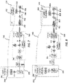
- FIGs. 2 and 3 are schematic views of the FIG. 1 architecture when used in respective downlink and uplink modes.
- FIG. 2 in the downlink mode, two instantiations of common components or modules are shown, indicative of a first instantiation corresponding to the first RU 102 and a second instantiation corresponding to the second RU 104.
- first instantiation indicated by reference numerals 202, 204, 206, 208 and 210.
- the DU 100 may comprise an OFDM encoding module 202, a deep neural network - digital predistortion (DNN-DPD) module 204, a DAC 206, a driver 208 and a DML 210.
- DNN-DPD deep neural network - digital predistortion
- the first RU 102 may comprise a PIN diode 212, a splitter module 214, a mixer 217, a local oscillator (LO) 216, a power amplifier 218, an antenna 220 and a beam controller 222.
- LO local oscillator
- the second RU 104 may comprise substantially the same components and functionality as the first RU 102.
- the OFDM encoding module 202 may correspond to the baseband module 112 shown in FIG. 1 .
- the OFDM encoding module 202 may encode received baseband digital signals into OFDM encoded digital signals or a variant thereof.
- the OFDM encoding module 202 may provide the OFDM encoded digital signals to the DNN-DPD module 204.
- the term digital signals may be used in both cases as it will be clear in context whether the digital signals are baseband or OFDM encoded digital signals.
- the DNN-DPD module 204 may comprise a part of the DFE 114 shown in FIG. 1 .
- the DNN-DPD module 204 may comprise a computational model for performing predistortion operation on the received digital signals to produce predistorted digital signals as output.
- the DNN-DPD module 204 may provide digital predistortion (DPD) whereby non-linearities introduced by one or more non-linear components of the shown signal-processing chain may be corrected or compensated for. This is by predistorting the digitally signals, effectively as the inverse of an estimated end-to-end non-linear channel.
- DPD digital predistortion
- the DNN-DPD module 204 may be pre-trained and later refined in separate training operations as will be explained later on.
- the DNN computational model 404 may comprise any machine learning model such as may be provided by one or more neural networks having any appropriate training scheme and structure.
- the term DNN need not imply any particular structure.
- digital signals input to the DNN-DPD module 204 may directly produce as output the predistorted digital signals, as indicated in FIG. 4 .
- the DNN-DPD module 204 may generate reference data, such as a look up table, that indicates output signals corresponding to given input signals.
- the DNN-DPD module 204 may be pre-trained and later refined in separate training operations as will be explained later on. Pre-training may be performed in advance of deployment of a particular DU-RU pairing, e.g. at a factory or in a laboratory, and therefore may take into account non-linearities measured in advance of deployment such that, when deployed, some form of DPD is already catered for. Refinement of the DNN-DPD module 204 may be performed "on-site" after deployment.
- the DNN computational model 204 may be particular to the particular DU-RU pair, e.g. the DU 100 and the first RU 102 taking into account its particular characteristics.
- the predistorted digital signals are passed to the DAC 206, which may be equivalent to the DAC 116 shown in FIG. 1 , for producing an analogue signal.
- the analogue signal is then passed to the driver 208 and then to the DML 210 which may modulate an optical signal based on the analogue signal.
- the DML 210 may be configured to modulate the optical signal using direct modulation and may also involve up-conversion to a particular IF.
- the modulated optical signal may be sent over, in this example, the first optical channel 106 to the first RU 102.
- a PIN diode 212 may demodulate the optical signal into an analogue signal for subsequent analogue processing via components equivalent to the AFE 124 shown in FIG. 1 .
- a LO 216 may up-convert via a mixer 217 the analogue signal to a radio frequency (RF) signal, whereafter the power amplifier 218 may amplify the RF signal for transmission via the antenna 220.
- RF radio frequency
- the digital signals may correspond to a particular beam to be transmitted using one or more antenna elements of the antenna 220 at the first RU 102.
- the digital signals may have one or more associated control signals which is or are indicative of a beam index which the beam controller 222 of the first RU 102 may decode for sending beam control signalling to the antenna 220.
- the one or more associated control signals may further indicate a schedule, indicative of a time or relative time when to transmit the beam.
- the one or more control signals may have a low data rate (relative to the digital signals).
- the one or more control signals may be transmitted at a different frequency (e.g. different IF) than the analogue signals, possibly separated by a guard band.
- the splitter module 214 may be configured as a filter, e.g. comprising one or more analogue frequency-selective filters, to recover the analogue signals separate from their associated control signalling. As indicated in FIG. 2 , the analogue signals may be passed to the mixer 217 whereas the one or more control signals may be passed to the beam controller 222.
- a plurality of digital signals may be provided by the OFDM encoding module 202, as well as one or more associated control signals, and the digital signals may be combined by, for example, an analogue coupler at different respective IFs and the splitter module 214 used as above to recover the different corresponding analogue signal streams as well as the control data which may indicate which beam to transmit at which time.
- the one or more control signals may be decoded by the beam controller 222 for controlling the antenna 220.
- the first RU 104 may comprise the antenna 220 and beam controller 222 as described above.
- the first RU 104 may further comprise a low noise amplifier (LNA) 302, a mixer 305 associated with a LO 304, a driver 306 and a DML 308.
- LNA low noise amplifier
- the DU 100 may comprise a PIN diode 212, being part of the optical interface equivalent to that mentioned in respect of FIG. 1 .
- the DU 100 may also comprise a splitter module 312, an ADC 314, an OFDM decoding module 316 and a DNN-equalizer module 318.
- the beam controller 222 may be configured to select via control signalling a particular beam for receiving an RF signal via the antenna 220 according to a schedule.
- the received RF signal may then pass via the LNA 302 to the mixer 305 where it may be down-converted to an IF, possibly combined with other signals, and then passes via the driver 306 to the DML 308 which modulates the one or more IF signals to an optical wavelength for transmission over the first optical channel 106 to the DU 100.
- the received optical signal(s) may be demodulated by the PIN diode 212, and the splitter module 312, if needed, may filter the one or more analogue signals which may then be converted into respective digital signals by the ADC 314.
- the digital signals may then be passed to the OFDM decoding module 316 for decoding in a known manner.
- the OFDM-decoded digital signals may then pass to the DNN-Equalizer module 318 which is configured to perform equalization (or linearization) based on another computational model which may directly generate as output an equalized or linearized version of the OFDM-decoded digital signal in the manner shown also in FIG. 4 .
- the order of the OFDM decoding module 316 and the DNN-Equalizer module 318 may be reversed.
- DNN-DPD module 204 may be provided in a given DU 100. Each may be pre-trained and subsequently refined, if needed.
- FIG. 5 is a flow diagram indicating processing operations that may be performed by the DU 100.
- the processing operations may be performed using hardware, firmware, software or a combination thereof.
- a first operation 5.1 may comprise modulating and/or demodulating an optical signal for respective transmission and/or reception of the optical signal using an optical channel connected to a remote radio unit.
- a second operation 5.2 may comprise performing, based on one or more pre-trained computational models, one or more operations on a digital signal corresponding to the optical signal for mitigating one or more non-linearities introduced by the optical modulating and/or demodulating means and the optical channel, the one or more pre-trained computational models being pre-trained based on feedback data indicative of said one or more non-linearities.
- FIGs. 6A and 6B are flow diagrams respectively indicating processing operations performed by the DU 100 for downlink and uplink modes of operation.
- the processing operations may be performed using hardware, firmware, software or a combination thereof.
- a first operation 6.1 may comprise providing a digital signal.
- a second operation 6.2 may comprise performing, based on a pre-trained computational model, a predistortion operation on the digital signal to produce a predistorted digital signal.
- a third operation 6.3 may comprise converting the predistorted digital signal to an analogue signal.
- a fourth operation 6.4 may comprise modulating an optical signal based on the analogue signal.
- a fifth operation 6.5 may comprise transmitting, via the optical channel to the radio unit, the optical signal for demodulation by an optical demodulator of the radio unit for transmission via one or more antennas of the radio unit.
- a first operation 7.1 may comprise receiving an optical signal received from a radio unit over the optical channel.
- a second operation 7.2 may comprise demodulating the optical signal to provide an analogue signal.
- a third operation 7.3 may comprise converting the analogue signal to a digital signal.
- a fourth operation 7.4 may comprise performing, based on the pre-trained computational model, an equalization operation on the digital signal or a digitally decoded version thereof to produce an equalized digital signal.
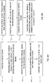
- FIGs. 7 and 8 show schematic views of pre-training setups, corresponding to FIGs. 2 and 3 for respective downlink and uplink modes, for generating the above-mentioned computational models which are referred to as the DNN-DPD module 204 and the DNN-Equalizer module 318.
- DNN does not necessarily mean that the computational models employ a particular topology or architecture.
- Pre-training maybe performed in advance of deployment of the particular DU-RU pair, e.g. the DU 100 and the first RU 102, at a factory or in a laboratory.
- each of the pre-training setups involve the use of a UE 110 in wireless signal communication of the first RU 102 for which the particular computational model is to be trained.
- FIG. 7 which shows a pre-training setup for training the DNN-DPD module 204 shown in FIG. 2 , relevant functional modules of the UE 110 are indicated.
- the UE 110 may comprise an antenna 702, an LNA 704, a mixer 706 associated with an LO 708, an ADC 710 and an OFDM decoding module 712.
- the function and operation of such functional modules is known.
- a feedback channel 730 is set-up between the output of the ADC 710 and an input of the DNN-DPD module 204.
- the feedback channel 730 provides training data to the input of the DNN-DPD module 204.
- the UE 110 may comprise an OFDM encoding module 804, a DAC 806, a mixer 808 associated with an LO 810, a power amplifier 812 and the above-mentioned antenna 702.
- the function and operation of such functional modules is known.
- a feedback channel 740 is set-up between the input of the OFDM encoding module 804 and an input of the DNN-Equalizer module 318.
- the feedback channel 740 provides training data to the input of the DNN-Equalizer module 318.
- the pre-training setups shown in FIGs. 7 and 8 enable pre-training of the DNN-DPD module 204 and the DNN-Equalizer module 318 based on end-to-end non-linearities that may be introduced by virtue of the RF and optical components.
- non-linearities may mainly come from the DML 210 and PIN diode 212 and also the power amplifier 218 in the RU 102.
- device-to-device variation may be small, and hence the pre-trained DNN-DPD 204 may provide a good initial computational model for deployment.
- non-linearities may mainly come from the DML 308 and PIN diode 310 and also the power amplifier 812 in the UE 110.
- refinement training may be performed to cater for field-specific non-linearities.
- Example pre-training processes for generating the above-mentioned DNN-DPD module 204 and DNN-Equalizer module 318 will now be explained.
- the DNN-DPD module 204 and DNN-Equalizer module 318 may be pre-trained using either direct or indirect learning techniques.
- a direct learning technique may involve approximating the non-linear "channel" and determining its inverse.
- An indirect learning technique may involve approximating the inverse of the non-linear channel. Both techniques are viable, and an overview of each will be described below.
- the non-linear channel may be denoted by H (e.g. a transfer function) and its learned inverse may be denoted by H -1 .
- the learned inverse H -1 of the non-linear channel H may represent the end-to-end non-linearities between, for example, the DAC at a transmitting end of the "channel" and the ADC at the receiving end.
- H -1 may represent the trained DNNs 204, 318.
- DNN whether the DNN-DPD module 204 or the DNN-Equalizer module 318 can vary and there may be trade-offs based on complexity, accuracy and robustness.
- FIG. 9B is illustrative of an indirect learning technique for DNN training.
- the DNN is configured to learn H -1 and may comprise a neural network or similar having an input layer, an output layer, and one or more hidden layers between the input and the output layers.
- Outputs of the non-linear channel H may be provided as training feature vectors for a DNN input layer, e.g. as feedback data, and the input of the non-linear channel H corresponding to the output may comprise labels of the feature vectors to compute prediction errors at the output layer of the DNN.
- FIG. 10 shows an example neural network implementation, which comprises an input layer of 21 nodes, a first hidden layer of 16 nodes, a second hidden layer of 4 nodes and an output layer of 1 node.
- FIG. 11 shows another example neural network implementation, which comprises an input layer of 21 nodes, first, second and third hidden layers of 4 nodes each, and an output layer of 1 node.
- Such example neural network implementations can be used both for training the DNN-DPD module 204 and the DNN-Equalizer module 318, using different datasets as indicated by the feedback channels 730, 740 in FIGs. 7 and 8 .
- FIGs. 9C and 9D are illustrative of a direct learning technique for DNN training. It will be seen that there are two DNN networks, one for learning the non-linear channel H and the other for learning its inverse H -1 .
- the two networks, H and H -1 may be connected via a batch-to-feature mapping mechanism which converts the output of one network, being a one-dimensional vector (a sequence of continuous output) into a matrix whose number of rows equals the number of nodes of the input layer of the other network.
- FIG. 12 which is an example network for the DNN-DPD module 204
- the error between the digitally encoded signal from, for example, the OFDM encoding module 202 at the DU 100 (which serves as a label, or "ground truth" parameter) and the reconstructed digitally encoded signal fed back from the UE 110 (see FIG. 7 ) may be calculated at the output of the channel network 1202 and then back-propagated to the inverse network 1204 for training, as indicated by the arrow 1208.
- FIG. 13 which is an example of a DNN network for the DNN-Equalizer module 318
- a channel network 1304 and an inverse network 1302 whereby the output node of the inverse network is fed-back to the output layer of the channel network.
- the error between the baseband digitally encoded signal prior to the OFDM encoding module 804 (which serves as a label, or "ground truth" parameter) fed back from the UE 110 (see FIG. 8 ) and the OFDM decoded digital signal may be calculated at the output of the inverse network 1302 and then back-propagated to the channel network 1304 for training, as indicated by the arrow 1308.
- the pre-trained DNN-DPD module 204 and DNN-Equalizer module 318 in the lab can be used as the default modules at the DU 100 to support each DU-RU pair in parallel.
- non-linearities may mainly come from the DML 210 and PIN diode 212 and also the power amplifier 218 in the RU 102.
- Device to device variation may be small and the need for refinement of the trained model can be accomplished during initial testing stage after deployment.
- a common DNN-DPD module at the DU 100 may be used for all connecting RUs 102, 104 if the power amplifier variation among the RUs is small, as indicated by similarities between DNN network coefficients.
- the non-linearities mainly come from the optical transceivers and the PA 812 at the UE 110, where UE to UE variation may be notable. Therefore, for each serving UE, if the SNR of the reconstructed signal is much weaker than expected (inferred from pilot symbols) the DNN-Equalizer module 318 coefficients can be refined in a decision-feedback manner. For example, digital signal at the UE 110 in the UL mode can be reconstructed at the DU 100 after that message being decoded successfully at the DU, thus eliminating the need of explicit feedback from the UE 110.
- the pre-trained DNN-DPD module 204 and DNN-Equalizer module 318 configured according to one of the above pre-training processes may be refined during initial field testing after deployment.
- the pre-trained DNN-DPD module 204 and DNN-Equalizer module 318 may be considered default modules used at the DU 100 for supporting each DU to RU pair in parallel.
- FIG. 7 diagram for the downlink mode may be represented by a first box 1402 representing the pre-trained DNN-DPD module 204 H o -1 and a second box representing the non-linear channel H mentioned above.
- the first box 1404 may represent a refined model H -1 which may replace the pre-trained DNN-DPD module 204 H o -1 once re-trained.
- This refinement may be performed based on further feedback from the UE 110 or another UE.
- Example refinement operations may comprise:
- FIGs. 16A and 16B In accordance with a direct learning technique for refinement of the DNN-DPD module 204, reference is made to FIGs. 16A and 16B .
- Example refinement operations may comprise:
- FIG. 8 diagram for the uplink mode may be represented by a first box 1702 representing the pre-trained DNN-Equalizer module 318 H o -1 and a second box 1703 representing the non-linear channel H mentioned above.
- the first box 1704 may represent a refined model H -1 which may replace the pre-trained DNN-Equalizer module 318 H o -1 once re-trained.
- a refined model for H -1 can be generated on a per-UE basis, for example based on UL pilot symbols or control sequences, and will replace the pre-trained DNN-Equalizer module 318. No explicit feedback from a UE is required.
- Example refinement operations may comprise:
- FIGs. 19A and 19B In accordance with a direct learning technique for refinement of the DNN-Equalizer module 318, reference is made to FIGs. 19A and 19B .
- Example refinement operations may comprise:
- Reconstruct the digital data x ⁇ of the uplink pilots or control sequences based on the output data x ⁇ from the DNN-Equalizer module 318 can be done, for example, by first demodulating and error-correction decoding x ⁇ to a bit sequence, and then performing corresponding error-correction encoding and modulation on the decoded bit sequence to construct the modulated sequence x ⁇ .
- the error-correction decoding of x ⁇ is successful, e.g. matching to known sequences defined by a standard, the reconstructed x ⁇ will be identical to the UE transmitted data x.
- the error-correction decoding and encoding process may be avoided and received symbols (with noise) may be directly mapped to modulated symbols (without noise) if the SNR is high.
- the trained computational models H 1 may be used as a multiple-input single-output (MISO) digital filter whose structure and coefficients are obtained through the pre-training and/or refinement processes described above.
- MISO multiple-input single-output
- a stream of digital data of length K may be input to the DNN network, generating K output data (representing predistorted data for the DNN-DPD module 204, or equalized/linearized data for the DNN-Equalizer module 318).
- the K sequence may be first rearranged to generate N parallel sequences, each of length K, before feeding to the N -input DNN network for filtering.
- the rearrangement of a K length sequence to an N-by-K matrix can be performed in many different ways, as long as the same approach is applied for both the training of the computational model and the using of the computational model for data processing.
- M zeros e.g., o ⁇ M ⁇ N/2
- the first constellation in FIG. 21A comprises only additive white Gaussian noise (AWGN) whereas the other added distortions are indicated alongside each of three other constellations in FIGs. 21B- D .
- AWGN additive white Gaussian noise
- the dominating distortion is the non-linearity which example embodiments herein are configured to mitigate by use of the DNN-DPD module 204 or the DNN-Equalizer module 318.
- FIGs. 22A - D indicate SNR and EVM measurements for approaches involving no DPD ( FIG. 22A ) and involving Volterra-based DPD ( FIG. 22B ) as well as indirect and direct learning DNN-DPD approaches as described herein ( FIGs. 22C and 22D ).
- FIG. 23 is a flow diagram indicating processing operations that may be performed by the DU 100 in performance of training the DNN-DPD and/or DPD-Equalizer modules 204, 318 according to example embodiments.
- the processing operations may be performed using hardware, firmware, software or a combination thereof.
- a first operation 23.1 may comprise providing a system comprising a DU apparatus connected to a RU by an optical channel.
- a second operation 23.2 may comprise training a computational model based on feedback data from a radio receiver in wireless signal communication with the RU.
- a third operation 23.3 which is optional, may comprise performance of refinement training.
- FIG. 24 shows an example apparatus that may comprise, for example, one or more components of the DU 100 or the first or second RU 102, 104.
- the apparatus may comprise at least one processor 2400 and at least one memory 2410 directly or closely connected or coupled to the processor.
- the memory 2410 may comprise at least one random access memory (RAM) 2410b and at least one read-only memory (ROM) 2410a.
- Computer program code (software) 2420 may be stored in the ROM 2410a.
- the apparatus may be connected to a transmitter path and a receiver path in order to obtain respective signals or data.
- the apparatus may be connected with a user interface (UI) for instructing the apparatus and/or for outputting data.
- UI user interface
- the at least one processor 2400 with the at least one memory 2410 and the computer program code 2420 may be arranged to cause the apparatus to at least perform methods described herein.
- the processor 2400 may be a microprocessor, plural microprocessors, a microcontroller, or plural microcontrollers.
- the memory may take any suitable form.
- FIG. 25 shows a non-transitory media 2500 according to some embodiments.
- the non-transitory media 2500 is a computer readable storage medium. It may be e.g. a CD, a DVD, a USB stick, a blue ray disk, etc.
- the non-transitory media 2500 may store computer program code causing an apparatus to perform operations described above when executed by a processor such as processor 2400 of FIG 14 .
- the non-transitory media 2500 may also store a work-product generated by means of performing the operations described above with reference to FIG. 23 .
- any mentioned apparatus and/or other features of particular mentioned apparatus may be provided by apparatus arranged such that they become configured to carry out the desired operations only when enabled, e.g. switched on, or the like. In such cases, they may not necessarily have the appropriate software loaded into the active memory in the non-enabled (e.g. switched off state) and only load the appropriate software in the enabled (e.g. on state).
- the apparatus may comprise hardware circuitry and/or firmware.
- the apparatus may comprise software loaded onto memory.
- Such software/computer programs may be recorded on the same memory/processor/functional units and/or on one or more memories/processors/ functional units.
- a particular mentioned apparatus may be pre-programmed with the appropriate software to carry out desired operations, and wherein the appropriate software can be enabled for use by a user downloading a "key", for example, to unlock/enable the software and its associated functionality.
- Advantages associated with such examples can include a reduced requirement to download data when further functionality is required for a device, and this can be useful in examples where a device is perceived to have sufficient capacity to store such pre-programmed software for functionality that may not be enabled by a user.
- Any mentioned apparatus/circuitry/elements/processor may have other functions in addition to the mentioned functions, and that these functions may be performed by the same apparatus/circuitry/elements/processor.
- One or more disclosed aspects may encompass the electronic distribution of associated computer programs and computer programs (which may be source/transport encoded) recorded on an appropriate carrier (e.g. memory, signal).
- Any "computer” described herein can comprise a collection of one or more individual processors/processing elements that may or may not be located on the same circuit board, or the same region/position of a circuit board or even the same device. In some examples one or more of any mentioned processors may be distributed over a plurality of devices. The same or different processor/processing elements may perform one or more functions described herein.
- signal may refer to one or more signals transmitted as a series of transmitted and/or received electrical/optical signals.
- the series of signals may comprise one, two, three, four or even more individual signal components or distinct signals to make up said signalling. Some or all of these individual signals may be transmitted/received by wireless or wired communication simultaneously, in sequence, and/or such that they temporally overlap one another.
- processors and memory may comprise a computer processor, Application Specific Integrated Circuit (ASIC), field-programmable gate array (FPGA), and/or other hardware components that have been programmed in such a way to carry out the inventive function.
- ASIC Application Specific Integrated Circuit
- FPGA field-programmable gate array
Applications Claiming Priority (1)
| Application Number | Priority Date | Filing Date | Title |
|---|---|---|---|
| FI20215092 | 2021-01-28 |
Publications (1)
| Publication Number | Publication Date |
|---|---|
| EP4037207A1 true EP4037207A1 (fr) | 2022-08-03 |
Family
ID=80595069
Family Applications (1)
| Application Number | Title | Priority Date | Filing Date |
|---|---|---|---|
| EP22152583.5A Pending EP4037207A1 (fr) | 2021-01-28 | 2022-01-21 | Appareil et système radio |
Country Status (3)
| Country | Link |
|---|---|
| US (1) | US11677476B2 (fr) |
| EP (1) | EP4037207A1 (fr) |
| CN (1) | CN114828021A (fr) |
Families Citing this family (1)
| Publication number | Priority date | Publication date | Assignee | Title |
|---|---|---|---|---|
| CN114584441A (zh) * | 2022-03-02 | 2022-06-03 | 中国人民解放军军事科学院战争研究院 | 一种基于深度学习的数字信号调制识别方法 |
Citations (2)
| Publication number | Priority date | Publication date | Assignee | Title |
|---|---|---|---|---|
| US20170366209A1 (en) * | 2016-06-20 | 2017-12-21 | Qualcomm Incorporated | Over the air acquisition of radio frequency impairment information |
| WO2020083508A1 (fr) * | 2018-10-26 | 2020-04-30 | Huawei Technologies Co., Ltd. | Unité radio à distance et unité centrale destinées à un système à entrées multiples et sorties multiples |
Family Cites Families (17)
| Publication number | Priority date | Publication date | Assignee | Title |
|---|---|---|---|---|
| US8260143B2 (en) * | 2008-03-12 | 2012-09-04 | Hypres, Inc. | Digital radio frequency tranceiver system and method |
| US8351877B2 (en) | 2010-12-21 | 2013-01-08 | Dali Systems Co. Ltfd. | Multi-band wideband power amplifier digital predistorition system and method |
| US8537911B2 (en) | 2011-02-21 | 2013-09-17 | Motorola Mobility Llc | Method and apparatus for reference signal processing in an orthogonal frequency division multiplexing communication system |
| CN104426829B (zh) * | 2013-08-30 | 2018-03-16 | 华为技术有限公司 | 一种基站回传方法、相关设备及基站回传系统 |
| JP2016082402A (ja) * | 2014-10-16 | 2016-05-16 | 富士通株式会社 | ベースバンド処理装置、無線装置、及び無線通信システム |
| JP2016092491A (ja) * | 2014-10-30 | 2016-05-23 | 富士通株式会社 | 無線送信システム及び歪み補償方法 |
| JP6750199B2 (ja) * | 2015-09-28 | 2020-09-02 | 富士通株式会社 | 通信装置および通信システム |
| CN106877825B (zh) * | 2017-01-25 | 2020-04-24 | 东南大学 | 基于带限的简化非线性滤波器的数字预失真装置及方法 |
| US10581469B1 (en) | 2017-04-17 | 2020-03-03 | DeepSig Inc. | Machine learning-based nonlinear pre-distortion system |
| EP3676966A4 (fr) * | 2017-08-30 | 2021-04-21 | Telefonaktiebolaget LM Ericsson (Publ) | Dispositif sans fil permettant de déterminer le meilleur faisceau d'antenne et procédé associé |
| CN109861754B (zh) * | 2017-11-30 | 2021-01-29 | 华为技术有限公司 | 非线性补偿的方法和光载无线通信系统 |
| EP3782304A1 (fr) * | 2018-05-28 | 2021-02-24 | Huawei Technologies Co., Ltd. | Unité radio distante et unité centrale pour station émettrice-réceptrice de base |
| US10699194B2 (en) * | 2018-06-01 | 2020-06-30 | DeepCube LTD. | System and method for mimicking a neural network without access to the original training dataset or the target model |
| WO2020125964A1 (fr) | 2018-12-19 | 2020-06-25 | Huawei Technologies Co., Ltd. | Station de base, et procédé de commande de la station de base |
| US11050491B2 (en) * | 2019-10-08 | 2021-06-29 | Fadhel M Ghannouchi | Radio access network using radio over fibre |
| CN111935037B (zh) * | 2020-06-09 | 2022-07-12 | 东南大学 | 基于深度学习的大规模多天线系统信道估计方法 |
| US11296735B1 (en) * | 2021-03-23 | 2022-04-05 | Qualcomm Incorporated | Distributed digital pre-distortion training |
-
2022
- 2022-01-21 EP EP22152583.5A patent/EP4037207A1/fr active Pending
- 2022-01-26 US US17/584,864 patent/US11677476B2/en active Active
- 2022-01-28 CN CN202210104741.9A patent/CN114828021A/zh active Pending
Patent Citations (2)
| Publication number | Priority date | Publication date | Assignee | Title |
|---|---|---|---|---|
| US20170366209A1 (en) * | 2016-06-20 | 2017-12-21 | Qualcomm Incorporated | Over the air acquisition of radio frequency impairment information |
| WO2020083508A1 (fr) * | 2018-10-26 | 2020-04-30 | Huawei Technologies Co., Ltd. | Unité radio à distance et unité centrale destinées à un système à entrées multiples et sorties multiples |
Also Published As
| Publication number | Publication date |
|---|---|
| US11677476B2 (en) | 2023-06-13 |
| CN114828021A (zh) | 2022-07-29 |
| US20220239380A1 (en) | 2022-07-28 |
Similar Documents
| Publication | Publication Date | Title |
|---|---|---|
| US11233561B1 (en) | Learning-based space communications systems | |
| US10090900B2 (en) | Excursion compensation in multipath communication systems having performance requirements parameters | |
| Rafique et al. | Digital preemphasis in optical communication systems: On the DAC requirements for terabit transmission applications | |
| RU2667071C1 (ru) | Каскадная модуляция волновой формы со встроенным сигналом управления для высокопроизводительного периферийного транзита мобильной связи | |
| Khanna et al. | Single-carrier 400G 64QAM and 128QAM DWDM field trial transmission over metro legacy links | |
| CN108028697B (zh) | 卫星通信中的失真后处理 | |
| WO2017005005A1 (fr) | Systèmes et procédés pour une architecture de messagerie de commande de rru pour des systèmes mimo massifs | |
| US20170163350A1 (en) | Iterative nonlinear compensation | |
| CN105979588A (zh) | 用于无线通信的高效前传通信的系统和方法 | |
| CN112088502B (zh) | 用于基站收发信台的射频拉远单元和中央单元 | |
| CN110380779A (zh) | 用于脉冲振幅调制信号的振幅相干检测 | |
| US20220045713A1 (en) | Equalizer assisted polynomial based linearity enhancement and self-interference canceler | |
| US11677476B2 (en) | Radio apparatus and system | |
| CN112913159B (zh) | 用于多输入多输出系统的远端射频单元和中央单元 | |
| Bosco | Flexible transceivers and the rate/reach trade-off | |
| US11909457B2 (en) | Equalizer digital self interference cancelation for hybrid MIMO transmitters | |
| US11750232B2 (en) | Hybrid GMP/equalizer digital self interference cancelation for MIMO transmitters | |
| Khanna et al. | Comparison of single carrier 200G 4QAM, 8QAM and 16QAM in a WDM field trial demonstration over 612 km SSMF | |
| JP2013016978A (ja) | 光通信システムおよび光通信方法 | |
| US11824692B2 (en) | Equalizer digital self-interference cancelation for MIMO transmitters | |
| van Uden | MIMO digital signal processing for optical spatial division multiplexed transmission systems | |
| Zhou | TRANSMISSION PERFORMANCE OPTIMIZATION IN FIBER-WIRELESS ACCESS NETWORKS USING MACHINE LEARNING TECHNIQUES | |
| US20240146579A1 (en) | Joint gain and phase mismatch canceller and equalizer for downlink aided by precoder signaling | |
| Rawat | Numerically stable digital predistortion model for over-the-air MIMO transmission | |
| Ionita et al. | An experimental study on the robustness of integer-forcing linear receivers |
Legal Events
| Date | Code | Title | Description |
|---|---|---|---|
| PUAI | Public reference made under article 153(3) epc to a published international application that has entered the european phase |
Free format text: ORIGINAL CODE: 0009012 |
|
| STAA | Information on the status of an ep patent application or granted ep patent |
Free format text: STATUS: THE APPLICATION HAS BEEN PUBLISHED |
|
| AK | Designated contracting states |
Kind code of ref document: A1 Designated state(s): AL AT BE BG CH CY CZ DE DK EE ES FI FR GB GR HR HU IE IS IT LI LT LU LV MC MK MT NL NO PL PT RO RS SE SI SK SM TR |
|
| STAA | Information on the status of an ep patent application or granted ep patent |
Free format text: STATUS: REQUEST FOR EXAMINATION WAS MADE |
|
| 17P | Request for examination filed |
Effective date: 20230119 |
|
| RBV | Designated contracting states (corrected) |
Designated state(s): AL AT BE BG CH CY CZ DE DK EE ES FI FR GB GR HR HU IE IS IT LI LT LU LV MC MK MT NL NO PL PT RO RS SE SI SK SM TR |