EP4037166B1 - Axialflussmotor mit feldschwächender funktionalität - Google Patents
Axialflussmotor mit feldschwächender funktionalität Download PDFInfo
- Publication number
- EP4037166B1 EP4037166B1 EP21154463.0A EP21154463A EP4037166B1 EP 4037166 B1 EP4037166 B1 EP 4037166B1 EP 21154463 A EP21154463 A EP 21154463A EP 4037166 B1 EP4037166 B1 EP 4037166B1
- Authority
- EP
- European Patent Office
- Prior art keywords
- rotor disk
- rotor
- shifting element
- relative
- axial
- Prior art date
- Legal status (The legal status is an assumption and is not a legal conclusion. Google has not performed a legal analysis and makes no representation as to the accuracy of the status listed.)
- Active
Links
Images


Classifications
-
- H—ELECTRICITY
- H02—GENERATION; CONVERSION OR DISTRIBUTION OF ELECTRIC POWER
- H02K—DYNAMO-ELECTRIC MACHINES
- H02K21/00—Synchronous motors having permanent magnets; Synchronous generators having permanent magnets
- H02K21/02—Details
- H02K21/021—Means for mechanical adjustment of the excitation flux
- H02K21/022—Means for mechanical adjustment of the excitation flux by modifying the relative position between field and armature, e.g. between rotor and stator
- H02K21/025—Means for mechanical adjustment of the excitation flux by modifying the relative position between field and armature, e.g. between rotor and stator by varying the thickness of the air gap between field and armature
- H02K21/026—Axial air gap machines
-
- H—ELECTRICITY
- H02—GENERATION; CONVERSION OR DISTRIBUTION OF ELECTRIC POWER
- H02K—DYNAMO-ELECTRIC MACHINES
- H02K16/00—Machines with more than one rotor or stator
- H02K16/02—Machines with one stator and two or more rotors
Definitions
- the present invention generally relates to the field of axial flux machines.
- it relates to a mechanical mechanism allowing to apply field weakening in an axial flux machine having a topology with one stator and two rotors.
- An axial flux machine is a type of electrical machine wherein a flux is generated in axial direction, the latter being the direction of the rotational axis.
- an axial flux machine comprises a disk- or ring-shaped rotor and stator, both having a central axis corresponding to the rotational axis of the machine, the stator and rotor being axially spaced apart by a narrow air gap.
- the rotor comprises permanent magnets, generating an axial magnetic flux
- the stator comprises a plurality of coils in which currents may run.
- the rotor is driven by magnetic fields generated by the stator currents, while in generator condition currents are induced in the stator coils due to the rotation of the rotor.
- Different topologies are known for axial flux machines, for example comprising one rotor and stator, one rotor and two stators, or two rotor disks positioned on both sides of a stator.
- the peak motor speed of an axial flux motor is limited by the maximum voltage level: during acceleration, the voltage level may increase until the maximum voltage of the power supply is reached, thereby preventing a further speed increase.
- a known principle to allow for a further acceleration is field weakening; by weakening the magnetic field, the motor characteristic is changed in such a way that a higher speed can be reached with a given voltage.
- Field weakening may be applied in an electronic way. For example, currents may be introduced into the stator that create magnetic fields opposed to the magnetic fields of the permanent magnets. However, this significantly reduces the efficiency and power of the motor at high speeds, being a main drawback of electronic field weakening.
- field weakening may also be applied in a mechanical way.
- Mechanical field weakening implies that the air gap between the rotor and stator is increased, typically by displacing the rotor or stator, thereby reducing the permanent magnetic field in the stator.
- the stator is axially shifted by means of a screw mechanism driven by an electric motor, thereby altering the stator's distance with respect to the rotor.
- Another example of mechanical field weakening is given in JP2005168190A , where a hydraulic piston is used for shifting the stator inside the motor's casing.
- EP1835600A3 a system is described for changing the axial gap between the stator and two respective rotor members.
- a second magnetic field is formed by the stator, which is used to generate an axial force adapted to move the rotor members in axial direction.
- two auxiliary rotors are provided, driven by the second magnetic field, and a power converting mechanism, arranged to convert torque of an auxiliary rotor into an axial force.
- the power converting mechanism e.g. makes use of a screw mechanism. Due to the second magnetic field, the auxiliary rotors rotate relatively to the shaft. Accordingly, the screw mechanism causes the auxiliary rotor to move axially, thereby pushing the main rotor and moving the latter in axial direction.
- the auxiliary rotors serve as two separate actuators, adapted to exert an axial force on the main rotors. Therefore, the axial displacement of the main rotors will only be synchronised, if the actuation itself occurs in a synchronised way, which in EP1835600A3 is realised by means of the second magnetic field.
- This solution fully relies on the two auxiliary rotors, and on the second magnetic field allowing to actuate both auxiliary rotors at the same time. A very specific implementation is therefore required, and without the presence of the two auxiliary rotors, nothing guarantees a synchronous movement of the main rotors.
- US6043578A1 discloses a magnetic coupling, allowing the coupling of two shafts without any direct mechanical connection between the shafts.
- a mechanism is described that allows to adjust the air gap between two magnet rotors.
- a barrel cam is used, having cam rollers projecting in cam slots.
- Turning the inner barrel causes an axial movement of the outer barrel, thereby pushing to a first magnet rotor.
- a second magnet rotor is connected to the first magnet rotor by means of a pivotable swing unit. Accordingly, by pushing the first magnet rotor in axial direction, the swing unit pivots, thereby causing the second magnet rotor to be pulled in opposite axial direction.
- US6043578A1 thus provides some kind of synchronisation mechanism, but in the application of a magnetic coupling. The solution relies on the pivoting swing unit, which may lack the robustness for use in other types of applications.
- the invention concerns an axial flux machine having a topology with one stator and two rotor disks.
- the rotor disks are mounted on both sides of the stator, and a first respectively second air gap, with length in axial direction, is present between the stator and the first respectively second rotor disk.
- An axial flux machine may equally be referred to as, for example, an axial air-gap electric motor or generator, or an axial flux permanent magnet machine.
- the machine is suited to operate as a motor and as a generator, depending on the working condition. According to different embodiments, different variants of the 'two rotor - one stator' topology are possible.
- the axial flux machine may be of the torus type, having a stator yoke, or may be of the YASA type, not having a stator yoke.
- the latter machine is also referred to as, for example, a yokeless and segmented armature (YASA) motor or generator, or simply a yokeless axial flux machine.
- YASA yokeless and segmented armature
- the rotor is defined as an assembly of components that are rotating during operation of the machine.
- the term rotor disk refers to a component mounted on the shaft and comprising the permanent magnets. Typically, it comprises a ring- or disk-shaped part carrying the permanent magnets. Additionally, the rotor disk may comprise other parts, protruding from the surface of the disk-shaped part.
- the rotor comprises a shifting element.
- the shifting element is rotatably mounted and is secured in axial direction relative to the stator.
- the shifting element may be integrated in the motor shaft, or be a part of the motor shaft.
- the shifting element is mounted between the motor shaft and the stator.
- the shifting element comprises a cylindrical sleeve, mounted coaxially with the motor shaft.
- the rotor further comprises a first and a second pair of mechanical mating elements.
- the first pair is adapted to mate the shifting element and the first rotor disk, while the second pair is adapted to mate the shifting element and the second rotor disk.
- Mechanically mating of two components refers to the coupling of those two components, in the sense that only specific movements of the components with respect to each other are possible.
- a pair of mechanical mating elements comprises two elements with a corresponding feature or complementary shape, that only may move relative to each other according to a specific trajectory, the latter being defined by the corresponding features or shapes.
- a pair of mechanical mating elements may comprise a pin connected to the rotor disk, and a helical groove, ridge or thread, provided in the shifting element.
- a guiding spline e.g. comprising teeth or ridges
- a groove describing a helical path is present in both the shifting element and the rotor, between which rolling elements, like in a ball or roller bearing, are provided.
- the shifting element comprises a first and a second guiding spline, adapted to mesh with a corresponding spline comprised in the first respectively second rotor disk.
- a spline or guiding spline refers to the presence of teeth, ridges or grooves on a component, being adapted to mesh with corresponding teeth, ridges or grooves in a mating piece.
- the spline in the component and the spline in the mating piece have a complementary shape, thereby defining a particular trajectory when moving the mating piece relative to the component.
- the splines comprised in the shifting element and rotor disk define the axial movement of the rotor disk relative to the shifting element while rotating the rotor disk relative to the shifting element.
- helical splines may be used, comprising helical grooves and corresponding teeth, or a ball spline comprising rolling elements between helical grooves.
- the two pairs of mechanical mating elements are such that an equal rotation of the first and the second rotor disk relative to the shifting element, results in an equally sized but opposite axial displacement of the first and second rotor disk relative to the shifting element.
- a first helical spline in clockwise direction and a second helical spline in counter-clockwise direction may be provided on the shifting element, both splines describing a spiral with equal pitch.
- the rotor further comprises a coupling element.
- the coupling element mechanically couples the first and the second rotor disk in such a way that a rotation of the first rotor disk relative to the second rotor disk is blocked, while an axial displacement of the first rotor disk relative to the second rotor disk is possible.
- the coupling element mechanically connects the first and the second rotor disk, and on the other hand, corresponding features provided in the coupling element and the rotor disks define an axial trajectory along which a rotor disk can move relative to the coupling element.
- Various embodiments are possible.
- a tongue-and-groove type connection may be established by providing straight grooves in the rotor and corresponding straight ribs in the coupling element.
- corresponding straight grooves may be provided in both the coupling element and the rotor disk, between which rolling elements like in a ball or roller bearing, are placed.
- the coupling element comprises a third guiding spline, adapted to mesh with a corresponding spline comprised in the first respectively second rotor disk, thereby mechanically coupling the first rotor disk to the second rotor disk in such a way that an axial displacement of the first rotor disk relative to the second rotor disk is allowed while a rotation of the first rotor disk relative to the second rotor disk is blocked.
- the term 'third' guiding spline is used to clearly distinguish from the aforementioned 'first' and 'second' guiding spline comprised in the shifting element, but has to be understood as an independent characteristic of the coupling element.
- the third guiding spline may comprise one or more elongated elements or bars, extending between both rotor disks and meshing with corresponding grooves in the rotor disk.
- the coupling element comprises a cylindrical sleeve, mounted coaxially with the rotor disks, and the third guiding spline is a parallel key spline, comprising straight grooves in axial direction.
- a ball spline comprising rolling elements positioned between straight grooves may be used.
- the shape of the splines in the coupling element and rotor disks is such that the first and second rotor disk may axially move relative to each other, but no rotation relative to one another is possible.
- the coupling element and the shifting element are mounted coaxially, having a central axis corresponding to the rotational axis.
- the coupling element and the shifting element each comprise a cylindrical sleeve, of which the diameter may be larger for the coupling element than for the shifting element, or vice versa.
- the shifting element is integrated in the motor shaft, and the coupling element is mounted coaxially with the motor shaft.
- the shifting element and coupling element have a particular interaction.
- the shifting element provides for a way to axially move a rotor disk relative to the shaft, during operation of the machine.
- this is not just an axial shift: any axial movement of a rotor disk goes along with a corresponding change of the angular position of the rotor disk relative to the shifting element.
- the coupling element always keeps the angular position of both rotor disks the same, any rotation of one rotor disk relative to the shifting element automatically results in the same rotation of the other rotor disk, which is converted back into an equally-sized but opposite axial movement of the other rotor disk by the shifting element.
- the particular interaction of the shifting element and coupling element results in a unique synchronisation mechanism, enabling to displace both rotor disks in a synchronous way. Consequently, using this synchronisation mechanism guarantees that both air gaps always remain the same during repositioning of the rotor disks.
- the invention enables the application of mechanical field weakening in axial flux machines with such a topology.
- actuation can be done in a simple way, thereby enabling a practical implementation of the field weakening functionality.
- a single hydraulic actuator may be used, positioned centrally between both rotor disks, wherein an increase of the hydraulic pressure results in an axial force on the two rotor disks.
- that force may be absorbed by only one of the rotor disks.
- actuation may even be done without any additional source of energy, simply relying on the change in torque exerted by the rotor: when evolving towards low-torque high-speed operation, a torque decrease automatically results in a change of the angular position of the rotor disk relative to the shifting element, causing the disk to move away from the stator.
- a counteracting element like a spring pushing both rotor disks apart, may be used to overcome the magnetic attraction between a rotor disk and the stator.
- the axial flux machine comprises an actuator, the actuator comprising one or more axially displaceable parts, and adapted to push the first and the second rotor disk apart by an axial movement of the one or more axially displaceable parts.
- An actuator is defined as a component that is responsible for moving and controlling a mechanism or system. In general terms, an actuator requires a control signal and a source of energy; when receiving a control signal, the actuator responds by converting the source's energy into mechanical motion.
- the actuator comprises one or more parts that are axially movable and that are in contact with or connected to one or both of the rotor disks.
- the path of the first guiding spline describes a left-handed helix
- the path of the second guiding spline describes a right-handed helix.
- the method further comprises:
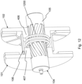
- Fig. 1 shows an axial flux machine 100 according to an embodiment of the invention, comprising a motor shaft 104, a stator 103, a first rotor disk 101 and a second rotor disk 102.
- the machine 100 has a rotational axis 110, defining the axial direction.
- the stator 103 comprises coils 107, typically copper windings wound around a ferromagnetic core, and the rotor disks 101, 102 comprise permanent magnets 108.
- the rotor disks 101, 102 are mounted on the shaft 104, on both sides of the stator 103, leaving a small air gap between a rotor disk 101, 102 and the stator 103.
- Bearings 109 are provided to mount the shaft 104 rotatably in a static housing.
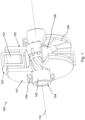
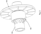
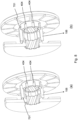
- the axial flux machine 100 comprises a shifting element 105 and a coupling element 106. These two elements, together with the rotor disk 102, are shown in Fig. 2 and Fig. 3 . As will further be explained underneath, the particular cooperation between the shifting element 105 and the coupling element 106 provides for a unique synchronisation mechanism, ensuring a synchronous displacement of the two rotor disks 101 and 102.
- Fig. 5 individually shows the shifting element 105.
- the shifting element 105 is integrated in the rotor shaft 104, meaning that it is part of the rotor shaft 104, as is also clear from Fig. 1 .
- the shifting element 105 comprises a first guiding spline 501 and a second guiding spline 502, embodied as grooves in the cylindrical outer surface of the shifting element 105.
- the path of the first guiding spline 501 describes a left-handed helix
- the path of the second guiding spline 502 describes a right-handed helix, both having the same pitch.
- the first guiding spline 501 of the shifting element 105 is adapted to mesh with the corresponding spline 401 of the first rotor disk 101.
- the first guiding spline 501 of the shifting element 105 and the spline 401 of the first rotor disk 101 together form a first pair of mechanical mating elements, thereby mating the first rotor disk 101 and the shifting element.
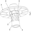
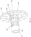
- the second guiding spline 502 of the shifting element 105 and the spline 402 of the second rotor disk 102 together form a second pair of mechanical mating elements, thereby mating the second rotor disk 101 and the shifting element 105. This is further illustrated in Fig. 6 , where the second rotor disk 102 is shown, mounted on the shifting element 105.
- the pairs of mechanical mating elements 501-401 and 502-402 define the trajectory that a rotor disk 101, 102 may follow when moving relatively to the shifting element 105. Indeed, when changing the angular position of a rotor disk 101, 102 relatively to the shifting element 105, the rotor disk 101, 102 moves axially with respect to the shifting element 105. Moreover, the pairs of mating elements 501-401 and 502-402 are chosen such that an equal rotation of the first 101 and the second rotor disk 102 relative to the shifting element 105 results in an equally sized but opposite axial displacement of the rotor disks 101, 102.
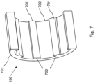
- the straight ribs 701 of the coupling element 106 may slide in the straight grooves 403, 404 of the rotor disks, thereby establishing a tongue-and-groove type of connection between the coupling element 106 and the first respectively second rotor disk 101, 102.
- the coupling element 106 mechanically connects or couples the two rotor disks 101, 102.
- the coupling element 106 together with the corresponding splines 403, 404 on the rotor disks, defines a specific trajectory when moving the rotor disks 101, 102 relatively to coupling element 106.
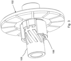
- Fig. 3 the assembly formed by the shifting element 105, the coupling element 106 and the rotor disks 101, 102 is illustrated. For clearness of representation, only one rotor disk 102 is shown.
- the coupling element 106 and the shifting element 105 are mounted coaxially, having a central axis corresponding to the rotational axis 110, with the shifting element 105 positioned internally with respect to the coupling element 106.
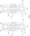
- FIG. 9 further illustrates the effect of the provided synchronisation mechanism.
- Figure 9 (a) shows a condition in which the rotor disks 101, 102 are positioned closely to the stator 103, leaving a small air gap 901, 902 on both sides of the stator 103. Typically, this corresponds to a high-torque low-speed operation of the axial flux motor.
- Figure 9 (b) shows another condition in which the rotor disks 101, 102 are positioned further away from the stator 103, leaving a larger air gap 903, 904 on both sides of the stator 103. In this mode, the permanent magnetic field in the stator 103 is weakened, thus allowing for a low-torque high-speed operation of the axial flux motor.
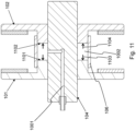
- Fig. 10 and Fig. 11 illustrates the use of a hydraulic actuator 1000 in an axial flux machine according to the embodiment described in the previous figures.
- the actuator 1000 comprises a fluid chamber 1002 and a fluid supply 1001.
- the fluid supply 1001 is implemented as a bore in the motor shaft 104, through which a hydraulic fluid under pressure is supplied to the fluid chamber 1002.
- the bore 1001 runs through one half of the shaft length, and may connect to a hydraulic coupling at one end of the motor shaft 104.
- the fluid chamber 1002 comprises a first wall 1101 and a second wall 1102, which are positioned between the rotor disks 101, 102 and are connected to the first respectively second rotor disk 101, 102.
- the walls 1101 and 1102 are axially displaceable, meaning that their position relative to the motor shaft 104 may be changed according to the axial direction. Due to an increase of the hydraulic pressure, an axial force 1103, 1104 is exerted on the first respectively second wall 1101, 1102, thereby axially displacing the walls 1101, 1102, and increasing the volume of the fluid chamber 1002. Accordingly, the rotor disks 101, 102 are pushed apart, thereby initiating an axial movement of the rotor disks 101, 102. Due to the shifting element 105, this axial movement is accompanied by a change of the angular position of the rotor disks 101, 102 relative to the shifting element 105.
- Fig. 12 illustrates the use of a spring 1200, in addition to the hydraulic actuator 1000.
- a helical spring 1200 is positioned between the cylindrical portions 407, 406 of the rotor disks 101, 102.
- the spring 1200 is in compressed condition, such that it pushes the first and second rotor disk 101, 102 apart.
- the spring 1200 and hydraulic actuator 1100 together provide the axially force pushing the rotor disks 101, 102 apart.
- a spring like in Fig. 12 may be positioned between the rotor disks 101, 102, but without any actuator being present. In such a case, actuation may just rely on the change of torque from the rotor disks 101, 102 when evolving towards a high-speed low-torque operation or vice versa.
- Fig. 13 shows another embodiment of the synchronisation mechanism.
- the coupling element 1300 is integrated in the motor shaft 104.
- the coupling element 1300 comprises a guiding spline, embodied as straight grooves 1301, 1302 extending in axial direction.
- the straight grooves 1302 are adapted to mesh with corresponding straight ribs 1305, the latter being provided on the inner surface of the cylindrical portion 1306 of the second rotor disk 1304.
- the straight grooves 1301 are adapted to mesh with straight ribs comprised in the first rotor disk, the latter not being shown in Fig. 13 .
Landscapes
- Engineering & Computer Science (AREA)
- Power Engineering (AREA)
- Permanent Magnet Type Synchronous Machine (AREA)
Claims (12)
- Axialflussmaschine (100), umfassend:- eine Welle (104) mit einer Drehachse (110) in axialer Richtung;- einen Stator (103) mit einer Mittelachse, die der Drehachse (110) entspricht, und eine Vielzahl von Spulen (107) umfassend, und- einen Rotor, der eine erste (101) und eine zweite Rotorscheibe (102) mit einer Mittelachse umfasst, die der Drehachse (110) entspricht, wobei die erste (101) und die zweite Rotorscheibe (102) auf beiden Seiten des Stators (103) montiert sind, wobei jede der Rotorscheiben (101, 102) durch einen Luftspalt (901, 902) axial von dem Stator (103) getrennt ist und Permanentmagnete (108) umfasst,wobei der Rotor Folgendes umfasst:- ein Schaltelement (105), das drehbar montiert ist, während es in axialer Richtung relativ zu dem Stator (103) gesichert ist;- ein erstes (501, 401) und ein zweites Paar (502, 402) von mechanischen passenden Elementen, die ausgelegt sind, um das Schaltelement (105) und die erste (101) bzw. zweite Rotorscheibe (102) zu verbinden, und eine axiale Verschiebung der ersten (101) bzw. zweiten Rotorscheibe (102) relativ zu dem Schaltelement (105) durch Drehen der ersten (101) bzw. zweiten Rotorscheibe (102) relativ zu dem Schaltelement (105) ermöglichen,wobei eine gleiche Drehung der ersten (101) und der zweiten Rotorscheibe (102) relativ zu dem Schaltelement (105) zu einer gleich großen, aber entgegengesetzten axialen Verschiebung der ersten (101) und der zweiten Rotorscheibe (102) relativ zu dem Schaltelement (105) führt;- ein Kopplungselement (106), das die erste (101) und die zweite Rotorscheibe (102) mechanisch koppelt, wodurch eine Drehung der ersten Rotorscheibe (101) relativ zu der zweiten Rotorscheibe (102) blockiert wird, während eine axiale Verschiebung der ersten Rotorscheibe (101) relativ zu der zweiten Rotorscheibe (102) ermöglicht wird,DADURCH GEKENNZEICHNET, DASS:- das erste bzw. zweite Paar von mechanischen passenden Elementen eine erste (501) bzw. zweite Führungsverzahnung (502) umfasst, die ausgelegt ist, um mit einer entsprechenden Verzahnung (401, 402) in Eingriff zu kommen, die in der ersten (101) bzw. zweiten Rotorscheibe (102) umfasst ist, wobei die erste Führungsverzahnung (501) und die zweite Führungsverzahnung (502) beide in einer zylindrischen Oberfläche des Schaltelements (105) umfasst sind;- das Kopplungselement (106) eine dritte Führungsverzahnung (700) umfasst, die ausgelegt ist, um mit einer entsprechenden Verzahnung (403, 404) in Eingriff zu kommen, die in der ersten (101) bzw. zweiten Rotorscheibe (102) umfasst ist, wobei die dritte Führungsverzahnung (700) in einer zylindrischen Oberfläche des Kopplungselements (106) umfasst ist;- das Schaltelement (105) und das Kopplungselement (106) separate Elemente sind, die koaxial montiert sind, wobei die zylindrische Oberfläche des Kopplungs- (106) und des Schaltelements (105) eine Mittelachse aufweist, die der Drehachse (110) entspricht.
- Axialflussmaschine (100) nach Anspruch 1,
wobei die Axialflussmaschine (100) einen Aktor (1000) umfasst, wobei der Aktor (1000) ein oder mehrere axial verschiebbare Teile (1101, 1002) umfasst und ausgelegt ist, um die erste (101) und die zweite Rotorscheibe (102) durch eine axiale Bewegung des einen oder der mehreren axial verschiebbaren Teile (1101, 1102) auseinanderzudrücken. - Axialflussmaschine (100) nach Anspruch 2,
wobei der Aktor (1000) eine erste (1101) und eine zweite axial verschiebbare Wand (1102) umfasst, die beide zwischen der ersten (101) und der zweiten Rotorscheibe (102) positioniert sind, wobei die erste (1101) bzw. zweite Wand (1102) in Kontakt mit der ersten (101) bzw. zweiten Rotorscheibe (102) ist. - Axialflussmaschine (100) nach Anspruch 3,wobei der Aktor (1000) eine Fluidkammer (1002) umfasst, die ausgelegt ist, um ein Hydraulikfluid aufzunehmen,und wobei die Fluidkammer (1002) die erste (1101) und die zweite axial verschiebbare Wand (1102) umfasst, sodass eine axiale Verschiebung der ersten (101) und der zweiten Rotorscheibe (102) das Volumen der Fluidkammer (1002) verändert.
- Axialflussmaschine (100) nach Anspruch 4,
wobei das Volumen der Fluidkammer (1002) basierend auf einem Hydraulikdruck gesteuert wird. - Axialflussmaschine (100) nach einem der vorhergehenden Ansprüche,
wobei das Schaltelement (105) in die Welle (104) integriert ist. - Axialflussmaschine (100) nach einem der vorhergehenden Ansprüche,
wobei der Weg der ersten Führungsverzahnung (501) eine linksgängige Helix beschreibt und der Weg der zweiten Führungsverzahnung (502) eine rechtsgängige Helix beschreibt. - Axialflussmaschine (100) nach einem der vorhergehenden Ansprüche,
wobei die dritte Führungsverzahnung (700) ausgelegt ist, um eine oder mehrere Nut- und FederVerbindungen zwischen dem Kopplungselement (106) und der ersten (101) bzw. zweiten Rotorscheibe (102) herzustellen. - Axialflussmaschine (100) nach einem der vorhergehenden Ansprüche,
wobei die dritte Führungsverzahnung (700) eine oder mehrere gerade Rippen (701) umfasst, die sich in axialer Richtung erstrecken, wobei die eine oder mehreren Rippen (701) ausgelegt sind, um mit einer oder mehreren geraden Nuten (403, 404) in Eingriff zu kommen, die in der ersten (101) und zweiten Rotorscheibe (102) umfasst sind und sich in axialer Richtung erstrecken. - Axialflussmaschine (100) nach einem der vorhergehenden Ansprüche,
wobei der Rotor ferner eine oder mehrere Federn (1200) umfasst, die zwischen der ersten (101) und der zweiten Rotorscheibe (102) positioniert sind, wobei die eine oder mehreren Federn (1200) ausgelegt sind, um die erste (101) und die zweite Rotorscheibe (102) auseinanderzudrücken. - Verfahren zum Umsetzen von mechanischer Feldschwächung in einer Axialflussmaschine (100), umfassend:- Bereitstellen einer Axialflussmaschine (100) mit einer Drehachse (110) in axialer Richtung, wobei die Axialflussmaschine (100) einen Stator (103) und einen Rotor umfasst, wobei der Stator (103) eine Mittelachse aufweist, die der Drehachse (110) entspricht, und eine Vielzahl von Spulen (107) umfasst, und der Rotor Folgendes umfasst:∘ eine erste (101) und eine zweite Rotorscheibe (102) mit einer Mittelachse, die der Drehachse (110) entspricht, wobei die erste (101) und die zweite Rotorscheibe (102) auf beiden Seiten des Stators (103) montiert sind, wobei jede der Rotorscheiben (101, 102) durch einen Luftspalt (901,902) axial von dem Stator (103) getrennt ist und Permanentmagnete (108) umfasst,∘ ein Schaltelement (105), das drehbar montiert ist, während es in axialer Richtung relativ zu dem Stator (103) gesichert ist;∘ ein erstes (501, 401) und ein zweites Paar (502, 402) von mechanischen passenden Elementen, die das Schaltelement (105) und die erste (101) bzw. zweite Rotorscheibe (102) verbinden, wobei das erste bzw. zweite Paar von mechanischen passenden Elementen eine erste (501) bzw. zweite Führungsverzahnung (502) umfasst, die ausgelegt ist, um mit einer entsprechenden Verzahnung (401, 402) in Eingriff zu kommen, die in der ersten (101) bzw. zweiten Rotorscheibe (102) umfasst ist, wobei die erste Führungsverzahnung (501) und die zweite Führungsverzahnung (502) beide in einer zylindrischen Oberfläche des Schaltelements (105) umfasst sind;∘ ein Kopplungselement (106), das die erste (101) und die zweite Rotorscheibe (102) mechanisch koppelt und eine dritte Führungsverzahnung (700) umfasst, die ausgelegt ist, um mit einer entsprechenden Verzahnung (403, 404) in Eingriff zu kommen, die in der ersten (101) bzw. zweiten Rotorscheibe (102) umfasst ist, wobei die dritte Führungsverzahnung (700) in einer zylindrischen Oberfläche des Kopplungselements (106) umfasst ist;wobei das Schaltelement (105) und das Kopplungselement (106) separate Elemente sind, die koaxial montiert sind, wobei die zylindrische Oberfläche der Kopplung (106) und des Schaltelements (105) eine Mittelachse aufweist, die der Drehachse (110) entspricht;- axiales Bewegen der ersten Rotorscheibe (101) relativ zu dem Schaltelement (105) durch das erste Paar von mechanischen passenden Elementen (501,401) aufgrund von Drehen der ersten Rotorscheibe (101) relativ zu dem Schaltelement (105), undaxiales Bewegen der zweiten Rotorscheibe (102) relativ zu dem Schaltelement (105) durch das zweite Paar von mechanischen passenden Elementen (502, 402) aufgrund von Drehen der zweiten Rotorscheibe (102) relativ zu dem Schaltelement (105),wobei eine gleiche Drehung der ersten (101) und der zweiten Rotorscheibe (102) relativ zu dem Schaltelement (105) zu einer gleich großen, aber entgegengesetzten axialen Verschiebung der ersten (101) und der zweiten Rotorscheibe (102) relativ zu dem Schaltelement (102) führt;- Blockieren einer Drehung der ersten Rotorscheibe (101) relativ zu der zweiten Rotorscheibe (102) durch das Kopplungselement (106) während der axialen Verschiebung der ersten (101) und der zweiten (102) Rotorscheibe.
- Verfahren nach Anspruch 11, ferner umfassend:- Bereitstellen eines Aktors (1000), der ein oder mehrere axial verschiebbare Teile (1101, 1102) umfasst;- axiales Bewegen des einen oder der mehreren axial verschiebbaren Teile (1102, 1102), wodurch die erste (101) und die zweite Rotorscheibe (102) auseinandergedrückt werden.
Priority Applications (4)
| Application Number | Priority Date | Filing Date | Title |
|---|---|---|---|
| EP21154463.0A EP4037166B1 (de) | 2021-01-29 | 2021-01-29 | Axialflussmotor mit feldschwächender funktionalität |
| PCT/EP2022/051923 WO2022162076A1 (en) | 2021-01-29 | 2022-01-27 | Axial flux motor with field weakening functionality |
| CN202280012201.6A CN117337535A (zh) | 2021-01-29 | 2022-01-27 | 具有磁场弱化功能的轴向磁通电机 |
| US18/272,661 US12388335B2 (en) | 2021-01-29 | 2022-01-27 | Axial flux motor with field weakening functionality |
Applications Claiming Priority (1)
| Application Number | Priority Date | Filing Date | Title |
|---|---|---|---|
| EP21154463.0A EP4037166B1 (de) | 2021-01-29 | 2021-01-29 | Axialflussmotor mit feldschwächender funktionalität |
Publications (3)
| Publication Number | Publication Date |
|---|---|
| EP4037166A1 EP4037166A1 (de) | 2022-08-03 |
| EP4037166C0 EP4037166C0 (de) | 2024-08-14 |
| EP4037166B1 true EP4037166B1 (de) | 2024-08-14 |
Family
ID=74494743
Family Applications (1)
| Application Number | Title | Priority Date | Filing Date |
|---|---|---|---|
| EP21154463.0A Active EP4037166B1 (de) | 2021-01-29 | 2021-01-29 | Axialflussmotor mit feldschwächender funktionalität |
Country Status (4)
| Country | Link |
|---|---|
| US (1) | US12388335B2 (de) |
| EP (1) | EP4037166B1 (de) |
| CN (1) | CN117337535A (de) |
| WO (1) | WO2022162076A1 (de) |
Families Citing this family (5)
| Publication number | Priority date | Publication date | Assignee | Title |
|---|---|---|---|---|
| US11936256B2 (en) | 2020-04-24 | 2024-03-19 | Jacobi Motors, Llc | Flux-mnemonic permanent magnet synchronous machine and magnetizing a flux-mnemonic permanent magnet synchronous machine |
| CN118100576A (zh) * | 2022-11-28 | 2024-05-28 | 通用汽车环球科技运作有限责任公司 | 可调气隙轴向磁通马达 |
| DE102023112743A1 (de) | 2023-05-15 | 2024-11-21 | Schaeffler Technologies AG & Co. KG | Verfahren zur regelung mechanisch feldgeschwächter elektrischer maschinen |
| DE102023003752B3 (de) | 2023-09-15 | 2024-12-19 | Mercedes-Benz Group AG | Elektrische Antriebseinrichtung mit einer Axialflussmaschine |
| DE102023003917A1 (de) | 2023-09-27 | 2025-03-27 | Mercedes-Benz Group AG | Elektrische Antriebseinrichtung mit einer Axialflussmaschine |
Family Cites Families (10)
| Publication number | Priority date | Publication date | Assignee | Title |
|---|---|---|---|---|
| US5477093A (en) * | 1993-05-21 | 1995-12-19 | Magna Force, Inc. | Permanent magnet coupling and transmission |
| US6043578A (en) * | 1997-04-14 | 2000-03-28 | Magna Force, Inc. | Adjustable magnetic coupler |
| US6348751B1 (en) | 1997-12-12 | 2002-02-19 | New Generation Motors Corporation | Electric motor with active hysteresis-based control of winding currents and/or having an efficient stator winding arrangement and/or adjustable air gap |
| JP4120573B2 (ja) | 2003-12-03 | 2008-07-16 | 日産自動車株式会社 | 可変エアーギャップ式永久磁石モータ |
| CN101051781B (zh) * | 2006-03-16 | 2011-01-19 | 日产自动车株式会社 | 电动机/发电机 |
| US7385332B2 (en) * | 2006-04-17 | 2008-06-10 | Hamilton Sundstrand Corporation | Permanent magnet dynamoelectric machine with axially displaceable permanent magnet rotor assembly |
| DE602009000023D1 (de) | 2008-02-21 | 2010-06-24 | Yamaha Motor Co Ltd | Radantreibende Vorrichtung und elektrisches Fahrzeug damit |
| JP5460566B2 (ja) * | 2010-12-13 | 2014-04-02 | 株式会社日立製作所 | アキシャルギャップ型回転電機 |
| SI3485558T1 (sl) * | 2016-07-18 | 2020-04-30 | Universiteit Gent | Stator za stroj z aksialnim magnetnim pretokom in postopek za izdelavo le-tega |
| EP3764526A1 (de) * | 2019-07-10 | 2021-01-13 | Magnax Bv | Kühlmechanismus eines stators für eine axialflussmaschine |
-
2021
- 2021-01-29 EP EP21154463.0A patent/EP4037166B1/de active Active
-
2022
- 2022-01-27 WO PCT/EP2022/051923 patent/WO2022162076A1/en not_active Ceased
- 2022-01-27 CN CN202280012201.6A patent/CN117337535A/zh active Pending
- 2022-01-27 US US18/272,661 patent/US12388335B2/en active Active
Also Published As
| Publication number | Publication date |
|---|---|
| US12388335B2 (en) | 2025-08-12 |
| WO2022162076A1 (en) | 2022-08-04 |
| EP4037166C0 (de) | 2024-08-14 |
| CN117337535A (zh) | 2024-01-02 |
| EP4037166A1 (de) | 2022-08-03 |
| US20240088765A1 (en) | 2024-03-14 |
Similar Documents
| Publication | Publication Date | Title |
|---|---|---|
| EP4037166B1 (de) | Axialflussmotor mit feldschwächender funktionalität | |
| JP5460566B2 (ja) | アキシャルギャップ型回転電機 | |
| US5300848A (en) | Dual permanent magnet generator planetary gear actuator and rotor phase shifting method | |
| JP5205594B2 (ja) | 回転電機 | |
| CN110431736B (zh) | 旋转-线性致动组件 | |
| JP2009531615A (ja) | アクチュエータ装置及びシフトクラッチ装置 | |
| JP2009126404A (ja) | ハイブリット車両 | |
| JP5502818B2 (ja) | 変速磁気カップリング装置 | |
| RU2538478C1 (ru) | Мотор-редуктор с интегрированным прецессирующим зубчатым колесом (варианты) | |
| TWI554007B (zh) | With inside and outside of the hollow rotor of motor delineated DC sub-structure | |
| RU2642683C2 (ru) | Вращательная механическая система с бесконтактным приводом | |
| JP2019146389A (ja) | 磁気歯車装置 | |
| EP1835600B1 (de) | Motor/Generator | |
| JP6893955B2 (ja) | ブレーキ付きモータ | |
| CN107710568A (zh) | 具有可变电机常数的电机、具有电机的执行装置和用于改变电机的电机常数的方法 | |
| CN110829715B (zh) | 一种可变磁场旋转电机 | |
| EP3688864B1 (de) | Stellglied mit veränderlicher reluktanz | |
| JP2002054706A (ja) | 無段変速機 | |
| CN102270922A (zh) | 凸轮机构调节转子间间隙的可调速的磁力偶合器 | |
| JP2017053465A (ja) | 速度変換機 | |
| EP3154179B1 (de) | Lineare elektrodynamische maschine mit verstellbarem hub | |
| WO2004109140A1 (en) | Electromechanical clutch actuator | |
| CN121098069A (zh) | 一种形状记忆合金驱动的可调速步进电机及方法 | |
| JPH06105532A (ja) | ワブルモータ応用の直動型アクチュエータ | |
| JPS61121739A (ja) | 電動アクチエ−タ |
Legal Events
| Date | Code | Title | Description |
|---|---|---|---|
| PUAI | Public reference made under article 153(3) epc to a published international application that has entered the european phase |
Free format text: ORIGINAL CODE: 0009012 |
|
| STAA | Information on the status of an ep patent application or granted ep patent |
Free format text: STATUS: REQUEST FOR EXAMINATION WAS MADE |
|
| 17P | Request for examination filed |
Effective date: 20211207 |
|
| AK | Designated contracting states |
Kind code of ref document: A1 Designated state(s): AL AT BE BG CH CY CZ DE DK EE ES FI FR GB GR HR HU IE IS IT LI LT LU LV MC MK MT NL NO PL PT RO RS SE SI SK SM TR |
|
| GRAP | Despatch of communication of intention to grant a patent |
Free format text: ORIGINAL CODE: EPIDOSNIGR1 |
|
| STAA | Information on the status of an ep patent application or granted ep patent |
Free format text: STATUS: GRANT OF PATENT IS INTENDED |
|
| INTG | Intention to grant announced |
Effective date: 20240326 |
|
| GRAS | Grant fee paid |
Free format text: ORIGINAL CODE: EPIDOSNIGR3 |
|
| GRAA | (expected) grant |
Free format text: ORIGINAL CODE: 0009210 |
|
| STAA | Information on the status of an ep patent application or granted ep patent |
Free format text: STATUS: THE PATENT HAS BEEN GRANTED |
|
| AK | Designated contracting states |
Kind code of ref document: B1 Designated state(s): AL AT BE BG CH CY CZ DE DK EE ES FI FR GB GR HR HU IE IS IT LI LT LU LV MC MK MT NL NO PL PT RO RS SE SI SK SM TR |
|
| REG | Reference to a national code |
Ref country code: GB Ref legal event code: FG4D |
|
| REG | Reference to a national code |
Ref country code: CH Ref legal event code: EP |
|
| REG | Reference to a national code |
Ref country code: DE Ref legal event code: R096 Ref document number: 602021017043 Country of ref document: DE |
|
| REG | Reference to a national code |
Ref country code: IE Ref legal event code: FG4D |
|
| U01 | Request for unitary effect filed |
Effective date: 20240826 |
|
| U07 | Unitary effect registered |
Designated state(s): AT BE BG DE DK EE FI FR IT LT LU LV MT NL PT RO SE SI Effective date: 20240903 |
|
| PG25 | Lapsed in a contracting state [announced via postgrant information from national office to epo] |
Ref country code: NO Free format text: LAPSE BECAUSE OF FAILURE TO SUBMIT A TRANSLATION OF THE DESCRIPTION OR TO PAY THE FEE WITHIN THE PRESCRIBED TIME-LIMIT Effective date: 20241114 |
|
| PG25 | Lapsed in a contracting state [announced via postgrant information from national office to epo] |
Ref country code: GR Free format text: LAPSE BECAUSE OF FAILURE TO SUBMIT A TRANSLATION OF THE DESCRIPTION OR TO PAY THE FEE WITHIN THE PRESCRIBED TIME-LIMIT Effective date: 20241115 Ref country code: PL Free format text: LAPSE BECAUSE OF FAILURE TO SUBMIT A TRANSLATION OF THE DESCRIPTION OR TO PAY THE FEE WITHIN THE PRESCRIBED TIME-LIMIT Effective date: 20240814 |
|
| PG25 | Lapsed in a contracting state [announced via postgrant information from national office to epo] |
Ref country code: IS Free format text: LAPSE BECAUSE OF FAILURE TO SUBMIT A TRANSLATION OF THE DESCRIPTION OR TO PAY THE FEE WITHIN THE PRESCRIBED TIME-LIMIT Effective date: 20241214 |
|
| PG25 | Lapsed in a contracting state [announced via postgrant information from national office to epo] |
Ref country code: HR Free format text: LAPSE BECAUSE OF FAILURE TO SUBMIT A TRANSLATION OF THE DESCRIPTION OR TO PAY THE FEE WITHIN THE PRESCRIBED TIME-LIMIT Effective date: 20240814 |
|
| PG25 | Lapsed in a contracting state [announced via postgrant information from national office to epo] |
Ref country code: RS Free format text: LAPSE BECAUSE OF FAILURE TO SUBMIT A TRANSLATION OF THE DESCRIPTION OR TO PAY THE FEE WITHIN THE PRESCRIBED TIME-LIMIT Effective date: 20241114 Ref country code: ES Free format text: LAPSE BECAUSE OF FAILURE TO SUBMIT A TRANSLATION OF THE DESCRIPTION OR TO PAY THE FEE WITHIN THE PRESCRIBED TIME-LIMIT Effective date: 20240814 |
|
| PG25 | Lapsed in a contracting state [announced via postgrant information from national office to epo] |
Ref country code: RS Free format text: LAPSE BECAUSE OF FAILURE TO SUBMIT A TRANSLATION OF THE DESCRIPTION OR TO PAY THE FEE WITHIN THE PRESCRIBED TIME-LIMIT Effective date: 20241114 Ref country code: PL Free format text: LAPSE BECAUSE OF FAILURE TO SUBMIT A TRANSLATION OF THE DESCRIPTION OR TO PAY THE FEE WITHIN THE PRESCRIBED TIME-LIMIT Effective date: 20240814 Ref country code: NO Free format text: LAPSE BECAUSE OF FAILURE TO SUBMIT A TRANSLATION OF THE DESCRIPTION OR TO PAY THE FEE WITHIN THE PRESCRIBED TIME-LIMIT Effective date: 20241114 Ref country code: IS Free format text: LAPSE BECAUSE OF FAILURE TO SUBMIT A TRANSLATION OF THE DESCRIPTION OR TO PAY THE FEE WITHIN THE PRESCRIBED TIME-LIMIT Effective date: 20241214 Ref country code: HR Free format text: LAPSE BECAUSE OF FAILURE TO SUBMIT A TRANSLATION OF THE DESCRIPTION OR TO PAY THE FEE WITHIN THE PRESCRIBED TIME-LIMIT Effective date: 20240814 Ref country code: GR Free format text: LAPSE BECAUSE OF FAILURE TO SUBMIT A TRANSLATION OF THE DESCRIPTION OR TO PAY THE FEE WITHIN THE PRESCRIBED TIME-LIMIT Effective date: 20241115 Ref country code: ES Free format text: LAPSE BECAUSE OF FAILURE TO SUBMIT A TRANSLATION OF THE DESCRIPTION OR TO PAY THE FEE WITHIN THE PRESCRIBED TIME-LIMIT Effective date: 20240814 |
|
| U20 | Renewal fee for the european patent with unitary effect paid |
Year of fee payment: 5 Effective date: 20250131 |
|
| PG25 | Lapsed in a contracting state [announced via postgrant information from national office to epo] |
Ref country code: SM Free format text: LAPSE BECAUSE OF FAILURE TO SUBMIT A TRANSLATION OF THE DESCRIPTION OR TO PAY THE FEE WITHIN THE PRESCRIBED TIME-LIMIT Effective date: 20240814 |
|
| PG25 | Lapsed in a contracting state [announced via postgrant information from national office to epo] |
Ref country code: CZ Free format text: LAPSE BECAUSE OF FAILURE TO SUBMIT A TRANSLATION OF THE DESCRIPTION OR TO PAY THE FEE WITHIN THE PRESCRIBED TIME-LIMIT Effective date: 20240814 |
|
| PG25 | Lapsed in a contracting state [announced via postgrant information from national office to epo] |
Ref country code: SK Free format text: LAPSE BECAUSE OF FAILURE TO SUBMIT A TRANSLATION OF THE DESCRIPTION OR TO PAY THE FEE WITHIN THE PRESCRIBED TIME-LIMIT Effective date: 20240814 |
|
| PGFP | Annual fee paid to national office [announced via postgrant information from national office to epo] |
Ref country code: GB Payment date: 20250121 Year of fee payment: 5 |
|
| U1N | Appointed representative for the unitary patent procedure changed after the registration of the unitary effect |
Representative=s name: DE CLERCQ & PARTNERS; BE |
|
| PLBE | No opposition filed within time limit |
Free format text: ORIGINAL CODE: 0009261 |
|
| STAA | Information on the status of an ep patent application or granted ep patent |
Free format text: STATUS: NO OPPOSITION FILED WITHIN TIME LIMIT |
|
| 26N | No opposition filed |
Effective date: 20250515 |
|
| REG | Reference to a national code |
Ref country code: CH Ref legal event code: PL |
|
| PG25 | Lapsed in a contracting state [announced via postgrant information from national office to epo] |
Ref country code: MC Free format text: LAPSE BECAUSE OF FAILURE TO SUBMIT A TRANSLATION OF THE DESCRIPTION OR TO PAY THE FEE WITHIN THE PRESCRIBED TIME-LIMIT Effective date: 20240814 |
|
| PG25 | Lapsed in a contracting state [announced via postgrant information from national office to epo] |
Ref country code: CH Free format text: LAPSE BECAUSE OF NON-PAYMENT OF DUE FEES Effective date: 20250131 |
|
| PG25 | Lapsed in a contracting state [announced via postgrant information from national office to epo] |
Ref country code: IE Free format text: LAPSE BECAUSE OF NON-PAYMENT OF DUE FEES Effective date: 20250129 |