EP4036692B1 - Taktiles feedback-system - Google Patents
Taktiles feedback-system Download PDFInfo
- Publication number
- EP4036692B1 EP4036692B1 EP22153856.4A EP22153856A EP4036692B1 EP 4036692 B1 EP4036692 B1 EP 4036692B1 EP 22153856 A EP22153856 A EP 22153856A EP 4036692 B1 EP4036692 B1 EP 4036692B1
- Authority
- EP
- European Patent Office
- Prior art keywords
- electronic device
- control unit
- sensing
- movable part
- sensing signal
- Prior art date
- Legal status (The legal status is an assumption and is not a legal conclusion. Google has not performed a legal analysis and makes no representation as to the accuracy of the status listed.)
- Active
Links
Images



Classifications
-
- G—PHYSICS
- G06—COMPUTING OR CALCULATING; COUNTING
- G06F—ELECTRIC DIGITAL DATA PROCESSING
- G06F3/00—Input arrangements for transferring data to be processed into a form capable of being handled by the computer; Output arrangements for transferring data from processing unit to output unit, e.g. interface arrangements
- G06F3/01—Input arrangements or combined input and output arrangements for interaction between user and computer
- G06F3/03—Arrangements for converting the position or the displacement of a member into a coded form
- G06F3/041—Digitisers, e.g. for touch screens or touch pads, characterised by the transducing means
- G06F3/0414—Digitisers, e.g. for touch screens or touch pads, characterised by the transducing means using force sensing means to determine a position
-
- G—PHYSICS
- G06—COMPUTING OR CALCULATING; COUNTING
- G06F—ELECTRIC DIGITAL DATA PROCESSING
- G06F3/00—Input arrangements for transferring data to be processed into a form capable of being handled by the computer; Output arrangements for transferring data from processing unit to output unit, e.g. interface arrangements
- G06F3/01—Input arrangements or combined input and output arrangements for interaction between user and computer
- G06F3/016—Input arrangements with force or tactile feedback as computer generated output to the user
-
- G—PHYSICS
- G02—OPTICS
- G02B—OPTICAL ELEMENTS, SYSTEMS OR APPARATUS
- G02B5/00—Optical elements other than lenses
- G02B5/005—Diaphragms
-
- G—PHYSICS
- G03—PHOTOGRAPHY; CINEMATOGRAPHY; ANALOGOUS TECHNIQUES USING WAVES OTHER THAN OPTICAL WAVES; ELECTROGRAPHY; HOLOGRAPHY
- G03B—APPARATUS OR ARRANGEMENTS FOR TAKING PHOTOGRAPHS OR FOR PROJECTING OR VIEWING THEM; APPARATUS OR ARRANGEMENTS EMPLOYING ANALOGOUS TECHNIQUES USING WAVES OTHER THAN OPTICAL WAVES; ACCESSORIES THEREFOR
- G03B30/00—Camera modules comprising integrated lens units and imaging units, specially adapted for being embedded in other devices, e.g. mobile phones or vehicles
-
- G—PHYSICS
- G03—PHOTOGRAPHY; CINEMATOGRAPHY; ANALOGOUS TECHNIQUES USING WAVES OTHER THAN OPTICAL WAVES; ELECTROGRAPHY; HOLOGRAPHY
- G03B—APPARATUS OR ARRANGEMENTS FOR TAKING PHOTOGRAPHS OR FOR PROJECTING OR VIEWING THEM; APPARATUS OR ARRANGEMENTS EMPLOYING ANALOGOUS TECHNIQUES USING WAVES OTHER THAN OPTICAL WAVES; ACCESSORIES THEREFOR
- G03B9/00—Exposure-making shutters; Diaphragms
- G03B9/02—Diaphragms
- G03B9/06—Two or more co-operating pivoted blades, e.g. iris type
-
- G—PHYSICS
- G06—COMPUTING OR CALCULATING; COUNTING
- G06F—ELECTRIC DIGITAL DATA PROCESSING
- G06F3/00—Input arrangements for transferring data to be processed into a form capable of being handled by the computer; Output arrangements for transferring data from processing unit to output unit, e.g. interface arrangements
- G06F3/01—Input arrangements or combined input and output arrangements for interaction between user and computer
- G06F3/03—Arrangements for converting the position or the displacement of a member into a coded form
- G06F3/033—Pointing devices displaced or positioned by the user, e.g. mice, trackballs, pens or joysticks; Accessories therefor
- G06F3/038—Control and interface arrangements therefor, e.g. drivers or device-embedded control circuitry
-
- G—PHYSICS
- G08—SIGNALLING
- G08B—SIGNALLING SYSTEMS, e.g. PERSONAL CALLING SYSTEMS; ORDER TELEGRAPHS; ALARM SYSTEMS
- G08B6/00—Tactile signalling systems, e.g. tactile personal calling systems
-
- H—ELECTRICITY
- H02—GENERATION; CONVERSION OR DISTRIBUTION OF ELECTRIC POWER
- H02K—DYNAMO-ELECTRIC MACHINES
- H02K11/00—Structural association of dynamo-electric machines with electric components or with devices for shielding, monitoring or protection
- H02K11/20—Structural association of dynamo-electric machines with electric components or with devices for shielding, monitoring or protection for measuring, monitoring, testing, protecting or switching
- H02K11/21—Devices for sensing speed or position, or actuated thereby
- H02K11/215—Magnetic effect devices, e.g. Hall-effect or magneto-resistive elements
-
- H—ELECTRICITY
- H02—GENERATION; CONVERSION OR DISTRIBUTION OF ELECTRIC POWER
- H02K—DYNAMO-ELECTRIC MACHINES
- H02K33/00—Motors with reciprocating, oscillating or vibrating magnet, armature or coil system
- H02K33/18—Motors with reciprocating, oscillating or vibrating magnet, armature or coil system with coil systems moving upon intermittent or reversed energisation thereof by interaction with a fixed field system, e.g. permanent magnets
-
- H—ELECTRICITY
- H02—GENERATION; CONVERSION OR DISTRIBUTION OF ELECTRIC POWER
- H02K—DYNAMO-ELECTRIC MACHINES
- H02K41/00—Propulsion systems in which a rigid body is moved along a path due to dynamo-electric interaction between the body and a magnetic field travelling along the path
- H02K41/02—Linear motors; Sectional motors
- H02K41/035—DC motors; Unipolar motors
- H02K41/0352—Unipolar motors
- H02K41/0354—Lorentz force motors, e.g. voice coil motors
- H02K41/0356—Lorentz force motors, e.g. voice coil motors moving along a straight path
-
- G—PHYSICS
- G02—OPTICS
- G02B—OPTICAL ELEMENTS, SYSTEMS OR APPARATUS
- G02B27/00—Optical systems or apparatus not provided for by any of the groups G02B1/00 - G02B26/00, G02B30/00
- G02B27/64—Imaging systems using optical elements for stabilisation of the lateral and angular position of the image
- G02B27/646—Imaging systems using optical elements for stabilisation of the lateral and angular position of the image compensating for small deviations, e.g. due to vibration or shake
Definitions
- the present invention relates to a tactile feedback system, and, in particular, to tactile feedback system that has a sensing module.
- US 2012/256864 A1 discloses a tactile sensation providing apparatus that includes a touch sensor, a detection unit, a tactile sensation providing unit, a main control unit, and a tactile sensation provision control unit.
- US 2010/156818 A1 discloses a method for processing touch inputs, wherein the method includes reading data from a multi-touch sensing device such as a multi-touch touch screen where the data pertains to touch input with respect to the multi-touch sensing device, and identifying at least one multi-touch gesture based on the data from the multi-touch sensing device and providing an appropriate multi-haptic response.
- a multi-touch sensing device such as a multi-touch touch screen where the data pertains to touch input with respect to the multi-touch sensing device, and identifying at least one multi-touch gesture based on the data from the multi-touch sensing device and providing an appropriate multi-haptic response.
- US 2006/241864 A1 discloses a point-and-send user interface, wherein a user can point a handheld unit at one of a plurality of electronic devices in a physical environment to select the electronic device and send data to it.
- An embodiment of the present invention provides a tactile feedback system that includes a fixed part, a movable part, and a driving assembly.
- the fixed part is affixed to an electronic device.
- the movable part can move relative to the fixed part.
- the driving assembly is configured to drive the movable part to move relative to the fixed part, thereby generating a tactile feedback force to a user.
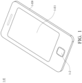
- FIG. 1 is a perspective diagram of an electronic device 1-E in accordance with an embodiment of the invention.
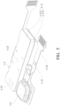
- FIG. 2 is a perspective diagram of a tactile feedback system 1-1 and a sensing module 1-2 disposed in the electronic device 1-E of FIG. 1 .
- the electronic device 1-E in this embodiment may be a cell phone or a tablet computer that comprises a housing 1-E0 and a screen 1-E1 disposed on the housing 1-E0.
- a sensing module 1-2 is disposed on a lower side of the housing 1-E0.
- the sensing module 1-2 may constitute at least a part of a touch pad, a button or other user interface of the electronic device 1-E.
- the sensing module 1-2 may comprise an Optical Finger Navigation (OFN) sensor, gyroscope, accelerometer, tactile switch, fingerprint sensor, pressure sensor, sound wave sensor, gas sensor, temperature sensor, or gas concentration sensor, not limited to the embodiments of the invention.
- OFN Optical Finger Navigation
- a tactile feedback system 1-1 is connected to the sensing module 1-2 and accommodated in the housing 1-E0 of the electronic device 1-E.
- the tactile feedback system 1-1 primarily comprises a fixed part 1-11 (including a frame 1-111 and a flat base 1-112), a vibrator 1-12 (movable part), a control unit 1-13, and a circuit assembly 1-14.
- the frame 1-111 is affixed in the housing 1-E0, and the base 1-112 is affixed to the bottom of the frame 1-111.
- the vibrator 1-12 can move in the frame 1-111 to provide vibration feedback (tactile feedback force) to the users.
- the sensing module 1-2, the circuit assembly 1-14, and the control unit 1-13 on the circuit assembly 1-14 are all affixed to the base 12 and located outside the frame 1-111.
- the sensing module 1-2 and the control unit 1-13 can be electrically connected to a CPU of the electronic device 1-E via the circuit assembly 1-14.
- the control unit 1-13 may comprise a controller IC, and it can transmit a control signal through the circuit assembly 1-14 to a driving assembly (not shown) in the frame 1-111, thereby driving the vibrator 1-12 (movable part) to vibrate relative to the frame 1-111.
- the driving assembly may comprise a coil disposed on the frame 1-111 and a magnet disposed on the vibrator 1-12.
- an electrical current control signal
- the magnet and the vibrator 1-12 can be driven to move relative to the frame 1-111.
- the fixed part 1-11, the vibrator 1-12 (movable part), and the driving assembly constitute at least a part of a linear resonant actuator (LRA) in the electronic device 1-E.
- LRA linear resonant actuator
- FIG. 3 is a function block diagram of the tactile feedback system 1-1, the sensing module 1-2 and the CPU 1-C in the electronic device 1-E.
- the sensing module 1-2 can detect the posture, velocity, acceleration of the electronic device 1-E or the user's input (e.g. touch or click) and then output a first sensing signal 1-S1 to the CPU 1-C in the electronic device 1-E accordingly.
- the CPU 1-C transmits a command signal 1-C1 to the control unit 1-13 according to the first sensing signal 1-S1, whereby the control unit 1-13 can be adjusted to a specific control mode.
- the vibrator 1-12 when different postures of the electronic device 1-E are detected, the vibrator 1-12 can be driven to vibrate at different amplitudes correspondingly. That is, the control unit 1-13 can output control signals of different modes according to the command signal 1-C1, thereby providing various kinds of tactile feedbacks to the users.
- the sensing module 1-2 can further transmit a second sensing signal 1-S2 to the control unit 1-13 by detecting the posture, velocity, or acceleration of the electronic device 1-E, and the second sensing signal 1-S2 does not pass through the CPU 1-C.
- the second sensing signal 1-S2 may be greater than, less than or equal to the first sensing signal 1-S1.
- control unit 1-13 can output the control signal to the driving assembly (e.g. the coil disposed on the frame 1-111) according to both of the command signal 1-C1 and the second sensing signal 1-S2.
- the vibrator 1-12 can be driven to move relative to the frame 1-111 and provide appropriate vibration feedback to the users.
- FIG. 4 is a schematic diagram of a first curve 1-R1 that represents the relationship between the motion of the vibrator 1-12 measured by an external equipment and the second sensing signal 1-S2 generated by the sensing module 1-2, wherein the first curve 1-R1 deviates from a first target curve 1-R1'.
- an external equipment (not shown) can be used to measure a motion (e.g. displacement, velocity, or acceleration) of the vibrator 1-12 relative to the frame 1-111.
- a first curve 1-R1 ( FIG. 4 ) can be obtained that represents the relationship between the motion of the vibrator 1-12 measured by the external equipment and the second sensing signal 1-S2 that is generated by the sensing module 1-2 detecting the motion of the vibrator 1-12.
- the first curve 1-R1 may deviate from a first target curve 1-R1' as shown in FIG. 4 .
- the external equipment can modify a setting parameter of the control unit 1-13 according to the first curve 1-R1, so as to achieve high motion control accuracy and efficiency of the vibrator 1-12 relative to the frame 1-111.
- the tactile feedback system 1-1 can perform accurate closed-loop motion or amplitude control of the vibrator 1-12 according to the second sensing signal 1-S2, thus providing appropriate and precise vibration feedback to the users. It should be noted that the calibration process does not involve the CPU 1-C of the electronic device 1-E.
- FIG. 5 is a perspective diagram of a tactile feedback system 1-1 and a sensing module 1-2 disposed in the electronic device 1-E, in accordance with an embodiment of the invention.
- FIG. 6 is a function block diagram of the tactile feedback system 1-1, the sensing module 1-2 and the CPU 1-C in the electronic device 1-E, in accordance with an embodiment of the invention.
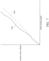
- FIG. 7 is a schematic diagram of a second curve 1-R2 that represents the relationship between the motion of the vibrator 1-12 measured by an external equipment and the third sensing signal 1-S3 generated by the sensor element 1-15, wherein the second curve 1-R2 deviates from a second target curve 1-R2'.
- FIGs. 5-7 is different from FIGs. 2-4 in that a sensor element 1-15 ( FIG.5 ) is provided in the frame 1-111 to detect the motion of the vibrator 1-12 relative to the frame 1-111, and the sensor element 1-15 can transmit a third sensing signal 1-S3 to the control unit 1-13 accordingly ( FIG.6 ).
- a sensor element 1-15 FIG.5
- the sensor element 1-15 can transmit a third sensing signal 1-S3 to the control unit 1-13 accordingly ( FIG.6 ).
- the sensor element 1-15 may also be directly disposed on the frame 1-111 or the base 1-112, not limited to the embodiments of the invention.
- the sensor element 1-15 may comprise a Hall sensor.
- control unit 1-13 can output a control signal to the driving assembly according to the command signal 1-C1, the second sensing signal 1-S2, and the third sensing signal 1-S3 thereby driving the vibrator 1-12 (movable part) to vibrate relative to the frame 1-111 and providing precise vibration feedback to the users.
- an external equipment (not shown) can be used to measure a motion (e.g. displacement, velocity, or acceleration) of the vibrator 1-12 relative to the frame 1-111.
- a second curve 1-R2 ( FIG. 7 ) can be obtained that represents the relationship between the motion of the vibrator 1-12 measured by the external equipment and the third sensing signal 1-S3 that is generated by the sensor element 1-15 detecting the motion of the vibrator 1-12.
- the second curve 1-R2 may deviate from a second target curve 1-R2' as shown in FIG. 7 .
- the external equipment can modify a setting parameter of the control unit 1-13 according to the first curve 1-R1 and the second curve 1-R2, so as to achieve high motion control accuracy and efficiency of the vibrator 1-12 relative to the frame 1-111.
- the tactile feedback system 1-1 can perform accurate closed-loop motion or amplitude control of the vibrator 1-12 according to the second and third sensing signals 1-S2 and 1-S3, thus providing comfortable and precise vibration feedback to the users. It should be noted that the calibration process does not involve the CPU 1-C of the electronic device 1-E.
- the sensing module 1-2 may comprise gyroscope and/or accelerometer to detect the posture of the electronic device 1-E.
- the control unit 1-13 controls the vibrator 1-12 to move in a first mode (e.g. continuous vibration) via the driving assembly.
- the control unit 1-13 controls the vibrator 1-12 to move in a second mode (e.g. intermittent vibration) via the driving assembly.
Landscapes
- Engineering & Computer Science (AREA)
- Physics & Mathematics (AREA)
- General Engineering & Computer Science (AREA)
- General Physics & Mathematics (AREA)
- Theoretical Computer Science (AREA)
- Human Computer Interaction (AREA)
- Power Engineering (AREA)
- Optics & Photonics (AREA)
- Combustion & Propulsion (AREA)
- Electromagnetism (AREA)
- Chemical & Material Sciences (AREA)
- Microelectronics & Electronic Packaging (AREA)
- Manipulator (AREA)
- Mechanical Light Control Or Optical Switches (AREA)
- User Interface Of Digital Computer (AREA)
- Reciprocating, Oscillating Or Vibrating Motors (AREA)
Claims (12)
- Elektronische Vorrichtung (1-E), umfassend:
ein taktiles Rückmeldungssystem (1-1), umfassend:einen festen Teil (1-11), der an der elektronischen Vorrichtung (1-E) befestigt ist;einen beweglichen Teil (1-12), der beweglich mit dem festen Teil (1-11) verbunden ist; undeine Antriebsanordnung, die den beweglichen Teil (1-12) antreibt, um sich relativ zu dem festen Teil (1-11) zu bewegen, und eine taktile Rückmeldungskraft für einen Benutzer erzeugt;wobei die elektronische Vorrichtung (1-E) ferner eine CPU (1-C) und ein Erfassungsmodul (1-2) umfasst, und das Erfassungsmodul (1-2) außerhalb des taktilen Rückmeldungssystems angeordnet ist und ein erstes Erfassungssignal (1-S1) an die CPU (1-C) überträgt, wobei das taktile Rückmeldungssystem ferner umfasst:eine Steuereinheit (1-13), die konfiguriert ist, um ein Steuersignal an die Antriebsanordnung zum Antreiben des beweglichen Teils (1-12), um sich relativ zu dem festen Teil (1-11) zu bewegen, zu übertragen;wobei die CPU (1-C) konfiguriert ist, um ein Befehlssignal (1-C1) an die Steuereinheit (1-13) zu übertragen, so dass die Steuereinheit (1-13) auf einen bestimmten Steuermodus eingestellt wird;wobei das Erfassungsmodul (1-2) ferner konfiguriert ist, um ein zweites Erfassungssignal (1-S2) ohne durch die CPU (1-C) zu gehen an die Steuereinheit (1-13) zu übertragen;dadurch gekennzeichnet, dass das taktile Rückmeldungssystem (1-1) ferner ein Sensorelement (1-15) umfasst, das in oder an dem festen Teil (1-11) angeordnet ist, um eine Bewegung des beweglichen Teils (1-12) zu erfassen,wobei das Sensorelement konfiguriert ist, um ein drittes Erfassungssignal (1-S3) an die Steuereinheit (1-13) zu übertragen,und die Steuereinheit (1-13) konfiguriert ist, um das Steuersignal gemäß dem zweiten und dritten Erfassungssignal an die Antriebsanordnung zu übertragen,wobei das taktile Rückmeldungssystem konfiguriert ist, um eine Bewegungssteuerung mit geschlossenem Regelkreis an dem beweglichen Teil (1-12) gemäß dem zweiten und dritten Erfassungssignal (1-S2 und 1-S3) durchzuführen,und wobei das Erfassungsmodul (1-2) ferner konfiguriert ist, um das zweite Erfassungssignal durch Erfassen einer Haltung, Geschwindigkeit oder Beschleunigung der elektronischen Vorrichtung (1-E) zu übertragen. - Elektronische Vorrichtung (1-E) nach Anspruch 1, wobei der feste Teil (1-11) einen Rahmen (1-111) und eine Basis (1-112), die mit dem Rahmen (1-111) verbunden ist, aufweist, die Antriebsanordnung und der bewegliche Teil (1-12) in dem Rahmen angeordnet sind und das Erfassungsmodul (1-2) und die Steuereinheit (1-13) außerhalb des Rahmens (1-111) angeordnet sind, wobei die Antriebsanordnung an dem festen Teil (1-11) befestigt ist.
- Elektronische Vorrichtung (1-E) nach Anspruch 1, wobei das Erfassungsmodul (1-2) auf einem flachen Element der elektronischen Vorrichtung (1-E) angeordnet ist und der feste Teil (1-11) an dem flachen Element befestigt ist, wobei das taktile Rückmeldungssystem (1-1) über eine Schaltungsanordnung (1-14), die auf dem flachen Element angeordnet ist, elektrisch mit dem Erfassungsmodul (1-2) verbunden ist.
- System, umfassend die elektronische Vorrichtung (1-E) nach Anspruch 1, ferner umfassend eine externe Ausrüstung, wobei eine erste Kurve (1-R1) erhalten wird, indem die externe Ausrüstung eine Bewegung des beweglichen Teils (1-12) und das von dem Erfassungsmodul (1-2) erzeugte zweite Erfassungssignal (1-S2) misst, und die erste Kurve (1-R1) die Beziehung zwischen der Bewegung des beweglichen Teils (1-12) und dem zweiten Erfassungssignal (1-S2) darstellt;
wobei die externe Ausrüstung konfiguriert ist, um einen Einstellparameter der Steuereinheit (1-13) gemäß der ersten Kurve (1-R1) zu modifizieren. - System, umfassend die elektronische Vorrichtung (1-E) nach Anspruch 1, ferner umfassend eine externe Ausrüstung, wobei eine erste Kurve (1-R1) erhalten wird, indem die externe Ausrüstung eine Bewegung des beweglichen Teils (1-12) und das von dem Erfassungsmodul (1-2) erzeugte zweite Erfassungssignal (1-S2) misst, und eine zweite Kurve (1-R2) erhalten wird, indem die externe Ausrüstung die Bewegung des beweglichen Teils (1-12) und das von dem Sensorelement erzeugte dritte Erfassungssignal misst, wobei die erste Kurve (1-R1) die Beziehung zwischen der Bewegung des beweglichen Teils (1-12) und dem zweiten Erfassungssignal (1-S2) darstellt, und die zweite Kurve (1-R2) die Beziehung zwischen der Bewegung des beweglichen Teils (1-12) und dem dritten Erfassungssignal darstellt;
wobei die externe Ausrüstung konfiguriert ist, um einen Einstellparameter der Steuereinheit (1-13) gemäß der ersten und zweiten Kurve (1-R1, 1-R2) zu modifizieren. - Elektronische Vorrichtung (1-E) nach Anspruch 1, wobei die CPU (1-C) konfiguriert ist, um das Befehlssignal gemäß dem ersten Erfassungssignal (1-S1) an die Steuereinheit (1-13) zu übertragen, und die Steuereinheit (1-13) konfiguriert ist, um das Steuersignal gemäß dem Befehlssignal an die Antriebsanordnung zu übertragen.
- Elektronische Vorrichtung (1-E) nach Anspruch 1, wobei, wenn das zweite Erfassungssignal (1-S2) eine erste Bedingung erfüllt, die Steuereinheit (1-13) konfiguriert ist, um den beweglichen Teil (1-12) über die Antriebsanordnung zu steuern, um sich in einem ersten Modus zu bewegen, und wenn das zweite Erfassungssignal (1-S2) eine zweite Bedingung erfüllt, die Steuereinheit (1-13) konfiguriert ist, um den beweglichen Teil (1-12) über die Antriebsanordnung zu steuern, um sich in einem zweiten Modus zu bewegen.
- Elektronische Vorrichtung (1-E) nach Anspruch 1, wobei das Erfassungsmodul (1-2) einen optischen Fingernavigationssensor (OFN), ein Gyroskop, einen Beschleunigungsmesser, einen taktilen Schalter, einen Fingerabdrucksensor, einen Drucksensor, einen Schallwellensensor, einen Gassensor, einen Temperatursensor oder einen Gaskonzentrationssensor umfasst.
- Elektronische Vorrichtung (1-E) nach Anspruch 1, wobei das Erfassungsmodul (1-2) mindestens einen Teil einer Benutzerschnittstelle der elektronischen Vorrichtung (1-E) bildet.
- Elektronische Vorrichtung (1-E) nach Anspruch 1, wobei das zweite Erfassungssignal (1-S2) größer oder kleiner als das erste Erfassungssignal (1-S1) ist.
- Elektronische Vorrichtung (1-E) nach Anspruch 1, wobei das zweite Erfassungssignal (1-S2) gleich dem ersten Erfassungssignal (1-S1) ist.
- Elektronische Vorrichtung (1-E) nach Anspruch 1, wobei der feste Teil (1-11), der bewegliche Teil (1-12) und die Antriebsanordnung mindestens einen Teil eines linearen Resonanzaktuators (LRA) bilden.
Priority Applications (1)
| Application Number | Priority Date | Filing Date | Title |
|---|---|---|---|
| EP25183842.1A EP4597273A3 (de) | 2021-01-29 | 2022-01-28 | Lichtmengeneinstellmechanismus |
Applications Claiming Priority (3)
| Application Number | Priority Date | Filing Date | Title |
|---|---|---|---|
| US202163143344P | 2021-01-29 | 2021-01-29 | |
| US202163230990P | 2021-08-09 | 2021-08-09 | |
| US202163276237P | 2021-11-05 | 2021-11-05 |
Related Child Applications (1)
| Application Number | Title | Priority Date | Filing Date |
|---|---|---|---|
| EP25183842.1A Division EP4597273A3 (de) | 2021-01-29 | 2022-01-28 | Lichtmengeneinstellmechanismus |
Publications (3)
| Publication Number | Publication Date |
|---|---|
| EP4036692A2 EP4036692A2 (de) | 2022-08-03 |
| EP4036692A3 EP4036692A3 (de) | 2022-09-14 |
| EP4036692B1 true EP4036692B1 (de) | 2025-06-25 |
Family
ID=80448621
Family Applications (2)
| Application Number | Title | Priority Date | Filing Date |
|---|---|---|---|
| EP22153856.4A Active EP4036692B1 (de) | 2021-01-29 | 2022-01-28 | Taktiles feedback-system |
| EP25183842.1A Pending EP4597273A3 (de) | 2021-01-29 | 2022-01-28 | Lichtmengeneinstellmechanismus |
Family Applications After (1)
| Application Number | Title | Priority Date | Filing Date |
|---|---|---|---|
| EP25183842.1A Pending EP4597273A3 (de) | 2021-01-29 | 2022-01-28 | Lichtmengeneinstellmechanismus |
Country Status (4)
| Country | Link |
|---|---|
| US (1) | US12386425B2 (de) |
| EP (2) | EP4036692B1 (de) |
| CN (1) | CN114816111A (de) |
| TW (1) | TWI912462B (de) |
Families Citing this family (5)
| Publication number | Priority date | Publication date | Assignee | Title |
|---|---|---|---|---|
| US12099251B2 (en) * | 2021-02-19 | 2024-09-24 | Tdk Taiwan Corp. | Optical component driving mechanism |
| DE102021212411A1 (de) * | 2021-11-04 | 2023-05-04 | Carl Zeiss Microscopy Gmbh | Verstellbare Blende für einen optischen Strahlengang |
| JP2024064224A (ja) * | 2022-10-27 | 2024-05-14 | オムロン株式会社 | 操作装置 |
| US20240142746A1 (en) * | 2022-10-28 | 2024-05-02 | Tdk Taiwan Corp. | Optical element driving mechanism |
| TWI866756B (zh) * | 2024-01-24 | 2024-12-11 | 久正光電股份有限公司 | 觸覺回饋裝置 |
Family Cites Families (14)
| Publication number | Priority date | Publication date | Assignee | Title |
|---|---|---|---|---|
| US6498624B1 (en) * | 1995-02-28 | 2002-12-24 | Canon Kabushiki Kaisha | Optical apparatus and image sensing apparatus mounted on the same surface of a board |
| US6211861B1 (en) * | 1998-06-23 | 2001-04-03 | Immersion Corporation | Tactile mouse device |
| US20060241864A1 (en) * | 2005-04-22 | 2006-10-26 | Outland Research, Llc | Method and apparatus for point-and-send data transfer within an ubiquitous computing environment |
| US8686952B2 (en) * | 2008-12-23 | 2014-04-01 | Apple Inc. | Multi touch with multi haptics |
| JP5437786B2 (ja) * | 2009-12-21 | 2014-03-12 | 京セラ株式会社 | 触感呈示装置 |
| US8686839B2 (en) * | 2011-11-01 | 2014-04-01 | Texas Instruments Incorporated | Closed-loop haptic or other tactile feedback system for mobile devices, touch screen devices, and other devices |
| US10108265B2 (en) | 2012-05-09 | 2018-10-23 | Apple Inc. | Calibration of haptic feedback systems for input devices |
| CN105511514B (zh) * | 2015-12-31 | 2019-03-15 | 歌尔股份有限公司 | 一种智能终端的触觉振动控制系统和方法 |
| US10890973B2 (en) * | 2016-08-31 | 2021-01-12 | Apple Inc. | Electronic device including multi-phase driven linear haptic actuator and related methods |
| US10248224B2 (en) * | 2016-10-25 | 2019-04-02 | Microsoft Technology Licensing, Llc | Input based on interactions with a physical hinge |
| KR20180105970A (ko) * | 2017-03-16 | 2018-10-01 | 마이크로엑츄에이터(주) | 조리개장치 |
| US11092721B2 (en) * | 2018-01-25 | 2021-08-17 | Tdk Taiwan Corp. | Optical system |
| US10459542B1 (en) * | 2018-06-01 | 2019-10-29 | Google Llc | Trackpad with capacitive force sensing and haptic feedback |
| US10852830B2 (en) | 2018-09-11 | 2020-12-01 | Apple Inc. | Power efficient, dynamic management of haptic module mechanical offset |
-
2022
- 2022-01-28 EP EP22153856.4A patent/EP4036692B1/de active Active
- 2022-01-28 EP EP25183842.1A patent/EP4597273A3/de active Pending
- 2022-01-28 TW TW111104162A patent/TWI912462B/zh active
- 2022-01-28 US US17/649,318 patent/US12386425B2/en active Active
- 2022-01-29 CN CN202210112152.5A patent/CN114816111A/zh active Pending
Also Published As
| Publication number | Publication date |
|---|---|
| EP4597273A3 (de) | 2025-10-29 |
| EP4597273A2 (de) | 2025-08-06 |
| EP4036692A2 (de) | 2022-08-03 |
| TWI912462B (zh) | 2026-01-21 |
| CN114816111A (zh) | 2022-07-29 |
| US12386425B2 (en) | 2025-08-12 |
| TW202232298A (zh) | 2022-08-16 |
| EP4036692A3 (de) | 2022-09-14 |
| US20220244785A1 (en) | 2022-08-04 |
Similar Documents
| Publication | Publication Date | Title |
|---|---|---|
| US10372214B1 (en) | Adaptable user-selectable input area in an electronic device | |
| US8698766B2 (en) | System integration of tactile feedback and touchscreen controller for near-zero latency haptics playout | |
| KR101130150B1 (ko) | 입력 장치, 정보 처리 장치, 리모트 컨트롤 장치 및 입력장치의 제어 방법 | |
| US9772688B2 (en) | Haptic feedback assembly | |
| EP2778847B1 (de) | Erzeugung von kontaktgeberbasierten haptischen Rückmeldungen | |
| US7663604B2 (en) | Input device and electronic device using the input device | |
| US20100020036A1 (en) | Portable electronic device and method of controlling same | |
| KR102724115B1 (ko) | 인간-컴퓨터 인터페이스 시스템 | |
| EP2390766B1 (de) | Elektronische Vorrichtung mit berührungsempfindlicher Anzeige und Verfahren zu deren Steuerung | |
| US20190146589A1 (en) | Compensated Haptic Rendering for Flexible Electronic Devices | |
| EP2327004A1 (de) | Tastrückmeldung zur tastensimulation in berührungsschirmen | |
| KR20050044412A (ko) | 피드백 발생을 위한 방법 및 장치 | |
| KR101328385B1 (ko) | 접촉식 손가락 마우스 및 이의 동작 방법 | |
| CN114168003A (zh) | 触控板组件、振动反馈方法、电子设备及存储介质 | |
| KR20090062190A (ko) | 촉감 입출력 장치 및 이것의 구동방법 | |
| WO2020110737A1 (ja) | 電子機器 | |
| JP5588023B2 (ja) | 電子機器 | |
| TWI784685B (zh) | 具有震動功能的觸控板 | |
| KR102257614B1 (ko) | 접촉감지식 입력장치로부터의 입력신호를 가변 촉각효과로 변환하는 시스템 및 방법 | |
| CN110225152B (zh) | 一种振动结构、振动方法和终端设备 | |
| JP2002157063A (ja) | 電子機器用多方向スイッチシステム及びそれを用いた電子機器 | |
| KR100666217B1 (ko) | 컴퓨터용 입력 시스템 | |
| CN110989769A (zh) | 笔记本电脑及控制方法 | |
| KR20070106147A (ko) | 정보 입력 장치의 입력여부 판별 방법 및 그 정보 입력장치 | |
| KR20100060722A (ko) | 햅틱 피드백 모듈이 구비된 입력장치 및 햅틱 피드백 생성방법 |
Legal Events
| Date | Code | Title | Description |
|---|---|---|---|
| PUAI | Public reference made under article 153(3) epc to a published international application that has entered the european phase |
Free format text: ORIGINAL CODE: 0009012 |
|
| STAA | Information on the status of an ep patent application or granted ep patent |
Free format text: STATUS: THE APPLICATION HAS BEEN PUBLISHED |
|
| AK | Designated contracting states |
Kind code of ref document: A2 Designated state(s): AL AT BE BG CH CY CZ DE DK EE ES FI FR GB GR HR HU IE IS IT LI LT LU LV MC MK MT NL NO PL PT RO RS SE SI SK SM TR |
|
| PUAL | Search report despatched |
Free format text: ORIGINAL CODE: 0009013 |
|
| AK | Designated contracting states |
Kind code of ref document: A3 Designated state(s): AL AT BE BG CH CY CZ DE DK EE ES FI FR GB GR HR HU IE IS IT LI LT LU LV MC MK MT NL NO PL PT RO RS SE SI SK SM TR |
|
| RIC1 | Information provided on ipc code assigned before grant |
Ipc: G02B 7/00 20210101ALI20220809BHEP Ipc: G06F 3/038 20130101ALI20220809BHEP Ipc: G06F 3/01 20060101AFI20220809BHEP |
|
| STAA | Information on the status of an ep patent application or granted ep patent |
Free format text: STATUS: REQUEST FOR EXAMINATION WAS MADE |
|
| 17P | Request for examination filed |
Effective date: 20230314 |
|
| RBV | Designated contracting states (corrected) |
Designated state(s): AL AT BE BG CH CY CZ DE DK EE ES FI FR GB GR HR HU IE IS IT LI LT LU LV MC MK MT NL NO PL PT RO RS SE SI SK SM TR |
|
| STAA | Information on the status of an ep patent application or granted ep patent |
Free format text: STATUS: EXAMINATION IS IN PROGRESS |
|
| 17Q | First examination report despatched |
Effective date: 20240506 |
|
| GRAP | Despatch of communication of intention to grant a patent |
Free format text: ORIGINAL CODE: EPIDOSNIGR1 |
|
| STAA | Information on the status of an ep patent application or granted ep patent |
Free format text: STATUS: GRANT OF PATENT IS INTENDED |
|
| RIC1 | Information provided on ipc code assigned before grant |
Ipc: G06F 3/038 20130101ALI20250220BHEP Ipc: G06F 3/01 20060101AFI20250220BHEP |
|
| INTG | Intention to grant announced |
Effective date: 20250304 |
|
| GRAS | Grant fee paid |
Free format text: ORIGINAL CODE: EPIDOSNIGR3 |
|
| GRAA | (expected) grant |
Free format text: ORIGINAL CODE: 0009210 |
|
| STAA | Information on the status of an ep patent application or granted ep patent |
Free format text: STATUS: THE PATENT HAS BEEN GRANTED |
|
| AK | Designated contracting states |
Kind code of ref document: B1 Designated state(s): AL AT BE BG CH CY CZ DE DK EE ES FI FR GB GR HR HU IE IS IT LI LT LU LV MC MK MT NL NO PL PT RO RS SE SI SK SM TR |
|
| REG | Reference to a national code |
Ref country code: GB Ref legal event code: FG4D |
|
| REG | Reference to a national code |
Ref country code: CH Ref legal event code: EP |
|
| REG | Reference to a national code |
Ref country code: DE Ref legal event code: R096 Ref document number: 602022016262 Country of ref document: DE |
|
| REG | Reference to a national code |
Ref country code: CH Ref legal event code: EP |
|
| REG | Reference to a national code |
Ref country code: IE Ref legal event code: FG4D |
|
| PG25 | Lapsed in a contracting state [announced via postgrant information from national office to epo] |
Ref country code: FI Free format text: LAPSE BECAUSE OF FAILURE TO SUBMIT A TRANSLATION OF THE DESCRIPTION OR TO PAY THE FEE WITHIN THE PRESCRIBED TIME-LIMIT Effective date: 20250625 |
|
| REG | Reference to a national code |
Ref country code: LT Ref legal event code: MG9D |
|
| PG25 | Lapsed in a contracting state [announced via postgrant information from national office to epo] |
Ref country code: NO Free format text: LAPSE BECAUSE OF FAILURE TO SUBMIT A TRANSLATION OF THE DESCRIPTION OR TO PAY THE FEE WITHIN THE PRESCRIBED TIME-LIMIT Effective date: 20250925 Ref country code: GR Free format text: LAPSE BECAUSE OF FAILURE TO SUBMIT A TRANSLATION OF THE DESCRIPTION OR TO PAY THE FEE WITHIN THE PRESCRIBED TIME-LIMIT Effective date: 20250926 |
|
| PG25 | Lapsed in a contracting state [announced via postgrant information from national office to epo] |
Ref country code: BG Free format text: LAPSE BECAUSE OF FAILURE TO SUBMIT A TRANSLATION OF THE DESCRIPTION OR TO PAY THE FEE WITHIN THE PRESCRIBED TIME-LIMIT Effective date: 20250625 |
|
| PG25 | Lapsed in a contracting state [announced via postgrant information from national office to epo] |
Ref country code: HR Free format text: LAPSE BECAUSE OF FAILURE TO SUBMIT A TRANSLATION OF THE DESCRIPTION OR TO PAY THE FEE WITHIN THE PRESCRIBED TIME-LIMIT Effective date: 20250625 |
|
| PG25 | Lapsed in a contracting state [announced via postgrant information from national office to epo] |
Ref country code: RS Free format text: LAPSE BECAUSE OF FAILURE TO SUBMIT A TRANSLATION OF THE DESCRIPTION OR TO PAY THE FEE WITHIN THE PRESCRIBED TIME-LIMIT Effective date: 20250925 |
|
| PG25 | Lapsed in a contracting state [announced via postgrant information from national office to epo] |
Ref country code: LV Free format text: LAPSE BECAUSE OF FAILURE TO SUBMIT A TRANSLATION OF THE DESCRIPTION OR TO PAY THE FEE WITHIN THE PRESCRIBED TIME-LIMIT Effective date: 20250625 |
|
| REG | Reference to a national code |
Ref country code: NL Ref legal event code: MP Effective date: 20250625 |
|
| PG25 | Lapsed in a contracting state [announced via postgrant information from national office to epo] |
Ref country code: NL Free format text: LAPSE BECAUSE OF FAILURE TO SUBMIT A TRANSLATION OF THE DESCRIPTION OR TO PAY THE FEE WITHIN THE PRESCRIBED TIME-LIMIT Effective date: 20250625 |
|
| PG25 | Lapsed in a contracting state [announced via postgrant information from national office to epo] |
Ref country code: PT Free format text: LAPSE BECAUSE OF FAILURE TO SUBMIT A TRANSLATION OF THE DESCRIPTION OR TO PAY THE FEE WITHIN THE PRESCRIBED TIME-LIMIT Effective date: 20251027 |
|
| REG | Reference to a national code |
Ref country code: AT Ref legal event code: MK05 Ref document number: 1807145 Country of ref document: AT Kind code of ref document: T Effective date: 20250625 |
|
| PG25 | Lapsed in a contracting state [announced via postgrant information from national office to epo] |
Ref country code: IS Free format text: LAPSE BECAUSE OF FAILURE TO SUBMIT A TRANSLATION OF THE DESCRIPTION OR TO PAY THE FEE WITHIN THE PRESCRIBED TIME-LIMIT Effective date: 20251025 |
|
| PGFP | Annual fee paid to national office [announced via postgrant information from national office to epo] |
Ref country code: GB Payment date: 20251127 Year of fee payment: 5 |
|
| PG25 | Lapsed in a contracting state [announced via postgrant information from national office to epo] |
Ref country code: AT Free format text: LAPSE BECAUSE OF FAILURE TO SUBMIT A TRANSLATION OF THE DESCRIPTION OR TO PAY THE FEE WITHIN THE PRESCRIBED TIME-LIMIT Effective date: 20250625 Ref country code: SM Free format text: LAPSE BECAUSE OF FAILURE TO SUBMIT A TRANSLATION OF THE DESCRIPTION OR TO PAY THE FEE WITHIN THE PRESCRIBED TIME-LIMIT Effective date: 20250625 |
|
| PG25 | Lapsed in a contracting state [announced via postgrant information from national office to epo] |
Ref country code: CZ Free format text: LAPSE BECAUSE OF FAILURE TO SUBMIT A TRANSLATION OF THE DESCRIPTION OR TO PAY THE FEE WITHIN THE PRESCRIBED TIME-LIMIT Effective date: 20250625 |
|
| PG25 | Lapsed in a contracting state [announced via postgrant information from national office to epo] |
Ref country code: PL Free format text: LAPSE BECAUSE OF FAILURE TO SUBMIT A TRANSLATION OF THE DESCRIPTION OR TO PAY THE FEE WITHIN THE PRESCRIBED TIME-LIMIT Effective date: 20250625 |
|
| PG25 | Lapsed in a contracting state [announced via postgrant information from national office to epo] |
Ref country code: EE Free format text: LAPSE BECAUSE OF FAILURE TO SUBMIT A TRANSLATION OF THE DESCRIPTION OR TO PAY THE FEE WITHIN THE PRESCRIBED TIME-LIMIT Effective date: 20250625 |
|
| PG25 | Lapsed in a contracting state [announced via postgrant information from national office to epo] |
Ref country code: SK Free format text: LAPSE BECAUSE OF FAILURE TO SUBMIT A TRANSLATION OF THE DESCRIPTION OR TO PAY THE FEE WITHIN THE PRESCRIBED TIME-LIMIT Effective date: 20250625 |
|
| PG25 | Lapsed in a contracting state [announced via postgrant information from national office to epo] |
Ref country code: ES Free format text: LAPSE BECAUSE OF FAILURE TO SUBMIT A TRANSLATION OF THE DESCRIPTION OR TO PAY THE FEE WITHIN THE PRESCRIBED TIME-LIMIT Effective date: 20250625 |
|
| REG | Reference to a national code |
Ref country code: DE Ref legal event code: R081 Ref document number: 602022016262 Country of ref document: DE Owner name: ACTUTEK CORPORATION, TW Free format text: FORMER OWNER: TDK TAIWAN CORP., TAOYUAN CITY, TW |
|
| REG | Reference to a national code |
Ref country code: GB Ref legal event code: 732E Free format text: REGISTERED BETWEEN 20260219 AND 20260225 |
|
| PG25 | Lapsed in a contracting state [announced via postgrant information from national office to epo] |
Ref country code: DK Free format text: LAPSE BECAUSE OF FAILURE TO SUBMIT A TRANSLATION OF THE DESCRIPTION OR TO PAY THE FEE WITHIN THE PRESCRIBED TIME-LIMIT Effective date: 20250625 |
|
| PGFP | Annual fee paid to national office [announced via postgrant information from national office to epo] |
Ref country code: DE Payment date: 20260128 Year of fee payment: 5 |
|
| PG25 | Lapsed in a contracting state [announced via postgrant information from national office to epo] |
Ref country code: IT Free format text: LAPSE BECAUSE OF FAILURE TO SUBMIT A TRANSLATION OF THE DESCRIPTION OR TO PAY THE FEE WITHIN THE PRESCRIBED TIME-LIMIT Effective date: 20250625 |
|
| PLBE | No opposition filed within time limit |
Free format text: ORIGINAL CODE: 0009261 |
|
| STAA | Information on the status of an ep patent application or granted ep patent |
Free format text: STATUS: NO OPPOSITION FILED WITHIN TIME LIMIT |
|
| REG | Reference to a national code |
Ref country code: CH Ref legal event code: L10 Free format text: ST27 STATUS EVENT CODE: U-0-0-L10-L00 (AS PROVIDED BY THE NATIONAL OFFICE) Effective date: 20260507 |