EP4036346A1 - Connection profile for building components adjacent to plaster - Google Patents
Connection profile for building components adjacent to plaster Download PDFInfo
- Publication number
- EP4036346A1 EP4036346A1 EP21191603.6A EP21191603A EP4036346A1 EP 4036346 A1 EP4036346 A1 EP 4036346A1 EP 21191603 A EP21191603 A EP 21191603A EP 4036346 A1 EP4036346 A1 EP 4036346A1
- Authority
- EP
- European Patent Office
- Prior art keywords
- leg
- component
- plaster
- sealing
- connection profile
- Prior art date
- Legal status (The legal status is an assumption and is not a legal conclusion. Google has not performed a legal analysis and makes no representation as to the accuracy of the status listed.)
- Pending
Links
Images


Classifications
-
- E—FIXED CONSTRUCTIONS
- E06—DOORS, WINDOWS, SHUTTERS, OR ROLLER BLINDS IN GENERAL; LADDERS
- E06B—FIXED OR MOVABLE CLOSURES FOR OPENINGS IN BUILDINGS, VEHICLES, FENCES OR LIKE ENCLOSURES IN GENERAL, e.g. DOORS, WINDOWS, BLINDS, GATES
- E06B1/00—Border constructions of openings in walls, floors, or ceilings; Frames to be rigidly mounted in such openings
- E06B1/62—Tightening or covering joints between the border of openings and the frame or between contiguous frames
-
- E—FIXED CONSTRUCTIONS
- E04—BUILDING
- E04F—FINISHING WORK ON BUILDINGS, e.g. STAIRS, FLOORS
- E04F13/00—Coverings or linings, e.g. for walls or ceilings
- E04F13/02—Coverings or linings, e.g. for walls or ceilings of plastic materials hardening after applying, e.g. plaster
- E04F13/04—Bases for plaster
- E04F13/06—Edge-protecting borders
-
- E—FIXED CONSTRUCTIONS
- E04—BUILDING
- E04G—SCAFFOLDING; FORMS; SHUTTERING; BUILDING IMPLEMENTS OR AIDS, OR THEIR USE; HANDLING BUILDING MATERIALS ON THE SITE; REPAIRING, BREAKING-UP OR OTHER WORK ON EXISTING BUILDINGS
- E04G21/00—Preparing, conveying, or working-up building materials or building elements in situ; Other devices or measures for constructional work
- E04G21/24—Safety or protective measures preventing damage to building parts or finishing work during construction
- E04G21/30—Safety or protective measures preventing damage to building parts or finishing work during construction against mechanical damage or dirt, e.g. guard covers of stairs
-
- E—FIXED CONSTRUCTIONS
- E06—DOORS, WINDOWS, SHUTTERS, OR ROLLER BLINDS IN GENERAL; LADDERS
- E06B—FIXED OR MOVABLE CLOSURES FOR OPENINGS IN BUILDINGS, VEHICLES, FENCES OR LIKE ENCLOSURES IN GENERAL, e.g. DOORS, WINDOWS, BLINDS, GATES
- E06B1/00—Border constructions of openings in walls, floors, or ceilings; Frames to be rigidly mounted in such openings
- E06B1/62—Tightening or covering joints between the border of openings and the frame or between contiguous frames
- E06B1/68—Tightening or covering joints between the border of openings and the frame or between contiguous frames by profiled external parts
-
- E—FIXED CONSTRUCTIONS
- E06—DOORS, WINDOWS, SHUTTERS, OR ROLLER BLINDS IN GENERAL; LADDERS
- E06B—FIXED OR MOVABLE CLOSURES FOR OPENINGS IN BUILDINGS, VEHICLES, FENCES OR LIKE ENCLOSURES IN GENERAL, e.g. DOORS, WINDOWS, BLINDS, GATES
- E06B1/00—Border constructions of openings in walls, floors, or ceilings; Frames to be rigidly mounted in such openings
- E06B1/62—Tightening or covering joints between the border of openings and the frame or between contiguous frames
- E06B2001/624—Tightening or covering joints between the border of openings and the frame or between contiguous frames with parts to be embedded in the stucco layer or otherwise linked to this layer
Definitions
- the invention relates to a connection profile for components adjoining plaster, in particular for window or door frames, with a two-part base leg, the inner leg of which has fastening means on the component side and is connected to an outer leg aligned parallel to the inner leg, the outer leg having a plaster leg protruding essentially perpendicularly thereto, and a plaster strip with a plaster stripping edge.
- connection profile for components adjacent to plaster which has a sealing leg which is fastened to the component with a layer of adhesive with the interposition of a sealing strip.
- the sealing tape together with the adhesive can be designed as a double-sided adhesive tape, for example.
- the sealing leg also has a plaster strip, which starts from the sealing leg and protrudes obliquely in the direction of the component.
- a detachable protective flap is formed over a material bottleneck, to which a protective film can be attached.
- the sealing strip is attached to the sealing leg with an adhesive whose holding power is adjusted in relation to that of the component-side adhesive in such a way that the sealing strip detaches from the sealing leg in the event of a pulling or shearing movement and the expanding, elastic foam element is released.
- connection profile that has a sealing leg that is attached directly to the component (e.g. a window frame) with an elastic sealing strip, with a plastering leg also being provided, which encloses an angle of approx. 90° with the sealing leg.
- This is a reveal connection profile, which is preferably used for the connection of thermally insulated facades, which rests on the sealing leg and the plaster leg.
- the plaster leg has a plaster strip which is slightly inclined in the direction of the component and which at least partially covers the front edge of the elastic sealing strip.
- the sealing leg has a receptacle, closed by the elastic sealing strip, for a folding element, with the elastic sealing strip closing the gap between the plaster and component-enlarging relative movement detaches from the sealing leg, the folding element unfolds and continues to seal the gap between plaster and component.
- the EP 2 116 682 A2 A sealing lip is arranged on the plastering leg of the connection profile, which bridges the elastic sealing strip when installed and seals the gap to the component. In order to ensure a reliable seal in the event of relative movements between the plaster and the component, the sealing lip must be equipped with an increased pre-tension.
- connection profile has become known, the base profile of which is designed in two parts, the leg that can be fastened to the component being fastened to an outer leg with the aid of a flexible strap.
- the inner leg which can be fastened to the component with the aid of a flexible sealing strip, has sealing lips on both sides of the flexible sealing strip, which is intended to compensate for component movements, which cover the gap to the component.
- sealing lips with an increased preload must be used in order to achieve the desired sealing effect with relative movements.
- the increased preload of the sealing lips can cause difficulties when installing the connection profiles, especially if the plastering work is only carried out at a later time.
- the object of the invention is to improve a connection profile for components adjoining plaster and their production in such a way that both production and assembly are simplified, with a permanent, tight seal between plaster and built-in part being guaranteed even when relative movements occur.
- an elastic sealing strip is arranged between the inner leg and the outer leg, which is suitable for at least partially compensating for component movements between the plaster and the component, and that the inner leg fixed to the component with a layer of adhesive or adhesive tape has a sealing strip that rests on the component Has sealing lip.
- the inner leg which is fixed to the component by a thin layer of adhesive or by double-sided adhesive tape, does not move relative to the component, so that the sealing lip can be produced with only a slight overhang over the component-side adhesive tape and has practically no disruptive pretension during assembly .
- This has the advantage that the connection strip can be easily glued to the built-in component a few days before the plastering work, without the risk of the connection profile being detached from the component on one side or over the entire surface due to the prestressing force of the sealing lip.
- the Invention arranged on the inner leg projecting away from the component sealing flange, the free end portion of parts of the outer leg, the plaster leg and / or the plaster strip rests sliding and sealing.
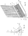
- connection profile 10 shown for components 30 adjoining the plaster 31 has a two-part base or sealing leg, namely an inner leg 11 fixed in position on the component 30 by means of a thin adhesive tape 17 and an outer leg 12 aligned parallel thereto. Between the inner leg 11 and the outer leg 12 is a compared to the adhesive tape 17, thicker, elastic sealing tape 16 is arranged, which can at least partially compensate for component movements between plaster 31 and component 30.
- the outer leg 12 has a plaster leg 13 protruding essentially perpendicularly therefrom, as well as a plaster strip 14 with a front plaster stripping edge 15 on.
- the plaster 31 consists of a base plaster layer or a filler that can be pulled off a projection 33 on the plaster strip 14 .
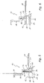
- the inner leg 11 fixed to the component 30 by means of adhesive tape 17 has a relatively short sealing lip 20, which can lie against the component 30 without significant prestressing, since in this area there are no relative movements between the plaster layer 31 and the component 30, for example a door or window frame. have to be compensated.
- a sealing flange 22 arranged in the front area of the inner leg 11 is then of particular advantage, the free end area 23 of which rests slidingly and sealingly on parts of the outer leg 12, the plastering leg 13 and/or the plaster strip 14 and the opening gap between the inner leg 11 and the outer leg 12 still covers.
- the sealing flange 22, or at least its end region 23 is guided in a substantially U-shaped receptacle 18 in the plaster strip 14, which is inclined obliquely in the direction of the component 30, in a sliding and sealing manner.
- the U-shaped receptacle 18 can also be formed in a stepped section of the plaster leg 13 and aligned perpendicularly to the component 30 (see, for example, 3 and 4 ).
- the sealing lip 20 and the sealing flange 22 can be produced as a one-piece extrudate 21 and attached to the inner leg 11 by means of co-extrusion, for example.
- the extrudate 21 is preferably fastened in such a way that a foot web 24 is extruded onto the inner leg 11, from which the sealing lip 20 protruding in the direction of the component 30 and the sealing flange 22 protruding away from the component 30 emanate.
- the footbridge 24 can preferably be attached to the front, plaster-side end of the inner leg 11 or to its front narrow side (see, for example, Figure 3, Figure 4 or 7 ) be extruded.
- the variant according to 3 is characterized by additional measures with which an opening gap between component 30 and plaster is sealed can be.
- the sealing lip 20 projecting in the direction of the component 30 has on its side facing away from the component a groove-shaped receptacle 26 running in the longitudinal direction of the profile, which accommodates a sealing web 27 protruding from the cleaning strip 14 in a sliding manner.
- the extrudate 21 consisting of the sealing lip 20 and the sealing flange 22 is extruded via a first foot web 24 on the inclined narrow side of the inner leg 11 and via a second foot web 24 ′ on the upper side of the inner leg 11 .
- a greater relative movement between the component and plaster can also be compensated for, since here the sealing flange 22 has a flexible tab or a flexible area 25 with which the end area 23 of the sealing flange 22 is attached to the base 24 .
- the flexible area 25 is folded up and can unfold accordingly in the event of a component movement.
- the two sealing elements - sealing lip 20 and sealing flange 22 - are attached to the inner leg 11 as separate extrudates.
- An unfoldable sealing loop 35 is arranged here as a further sealing element, which is fastened to the end of the cleaning strip 14 on the component side, starting from the rear side of the sealing lip 20 .
- connection profile 10 shows a simple, compact variant of the connection profile 10, in which the extrudate 21 of sealing lip 20 and sealing flange 22 is attached to the front (plaster side) narrow side of the inner leg 11.
- the sealing flange 22 slides against the inside of the plaster strip 14 and the underside of the outer leg 12 and is pressed against the plaster strip 14 in a sealing manner by an elastic support element 36 which is arranged on the underside of the outer leg 12 .
- An unfoldable sealing loop 35 which is fastened to the inner leg 11 starting from the underside of the outer leg 12 serves as a further sealing element.
- a detachable protective leg 28 for receiving a cover film can be attached to the plaster removal edge 15 of the plaster strip 14 .
- a reinforcement grid 32 can be attached to the plaster leg 13, preferably with the aid of a co-extruded retaining strip 29.
- Another advantage of the connection profile 10 according to the invention is in the Figures 11a and 11b shown. Based on a previously described variant (see Figures 2a, 2b ), these advantages, which lead to improved embedding of the plaster leg 13 in the filler of the plaster layer 31, are presented.
- a connecting profile 10 for a component 30 adjoining an insulating element 32 including plaster 31 is shown, with a base leg 11, 12 which has a fastening means 17 on the component side.
- the base limb 11, 12 (a one-piece base limb without a sealing strip would also be possible) has a plaster limb 13 with wall openings 37 that protrudes essentially perpendicularly thereto. In its installed position, the plastering leg 13 is at a distance from the insulating element 32 at least in the region of its wall openings 37 in such a way that a free area 38 is formed between the plastering leg 13 and the insulating element 32 .
- the release area 38 is delimited at the top by a supporting web 39 of the plaster leg 13 directed towards the insulating board 32 .
- a hollow chamber is formed behind the plaster leg 13 and the base coat or the filler can penetrate through the wall openings 37 of the plaster leg 13 into the hollow chamber formed by the exemption 38 and enclose the plaster leg 13 on both sides.
- a further advantage is that the back of the base leg or the two legs 11 and 12 and the free end of the support web 39 lie in a common plane ⁇ , which is aligned perpendicular to the sealing plane (surface of the component 30).
- the connection profile 10 can be aligned directly on the insulating element 40 in an advantageous manner, without having to make cutouts or adjustments on the insulating element.
Abstract
Die Erfindung betrifft ein Anschlussprofil (10) für an Putz (31) angrenzende Bauteile (30), insbesondere für Fenster- oder Türstöcke, mit einem zweiteiligen Basisschenkel (11, 12), dessen Innenschenkel (11) bauteilseitige Befestigungsmittel aufweist und mit einem parallel zum Innenschenkel (11) ausgerichteten Außenschenkel (12) verbunden ist, wobei der Außenschenkel (12) einen im Wesentlichen senkrecht dazu abstehenden Einputzschenkel (13), sowie eine Putzleiste (14) mit einer Putzabzugskante (15) aufweist. Erfindungsgemäß ist zwischen dem Innenschenkel (11) und dem Außenschenkel (12) ein elastisches Dichtband (16) angeordnet, das geeignet ist, Bauteilbewegungen zwischen Putz und Bauteil zumindest teilweise zu kompensieren, wobei der mit einer Kleberschicht oder einem Klebeband (17) am Bauteil (30) fixierte Innenschenkel (11) eine am Bauteil (30) anliegende Dichtlippe (20) aufweist.The invention relates to a connection profile (10) for components (30) adjoining plaster (31), in particular for window or door frames, with a two-part base leg (11, 12), the inner leg (11) of which has fastening means on the component side and with a parallel to the The inner leg (11) is connected to the outer leg (12), the outer leg (12) having a plastering leg (13) protruding essentially perpendicularly thereto, and a plaster strip (14) with a plaster removal edge (15). According to the invention, an elastic sealing tape (16) is arranged between the inner leg (11) and the outer leg (12), which is suitable for at least partially compensating for component movements between the plaster and the component, with the tape being attached to the component with an adhesive layer or an adhesive tape (17). 30) fixed inner leg (11) has a sealing lip (20) resting on the component (30).
Description
Die Erfindung betrifft ein Anschlussprofil für an Putz angrenzende Bauteile, insbesondere für Fenster- oder Türstöcke, mit einem zweiteiligen Basisschenkel, dessen Innenschenkel bauteilseitige Befestigungsmittel aufweist und mit einem parallel zum Innenschenkel ausgerichteten Außenschenkel verbunden ist, wobei der Außenschenkel einen im Wesentlichen senkrecht dazu abstehenden Einputzschenkel, sowie eine Putzleiste mit einer Putzabzugskante aufweist.The invention relates to a connection profile for components adjoining plaster, in particular for window or door frames, with a two-part base leg, the inner leg of which has fastening means on the component side and is connected to an outer leg aligned parallel to the inner leg, the outer leg having a plaster leg protruding essentially perpendicularly thereto, and a plaster strip with a plaster stripping edge.
In diesem Zusammenhang ist aus der
In der
Schließlich ist aus der
Aufgabe der Erfindung ist es, ein Anschlussprofil für an Putz angrenzende Bauteile und deren Herstellung derart zu verbessern, dass sowohl die Herstellung als auch die Montage vereinfacht wird, wobei ein dauerhafter, dichter Abschluss zwischen Putz und Einbauteil auch beim Auftreten von Relativbewegungen gewährleistet sein soll.The object of the invention is to improve a connection profile for components adjoining plaster and their production in such a way that both production and assembly are simplified, with a permanent, tight seal between plaster and built-in part being guaranteed even when relative movements occur.
Erfindungsgemäß wird dies dadurch erreicht, dass zwischen dem Innenschenkel und dem Außenschenkel ein elastisches Dichtband angeordnet ist, das geeignet ist, Bauteilbewegungen zwischen Putz und Bauteil zumindest teilweise zu kompensieren, sowie dass der mit einer Kleberschicht oder einem Klebeband am Bauteil fixierte Innenschenkel eine am Bauteil anliegende Dichtlippe aufweist. Der Innenschenkel, der durch eine dünne Kleberschicht oder durch ein Doppelklebeband am Bauteil fixiert ist, führt keine Relativbewegungen in Bezug auf das Bauteil aus, sodass die Dichtlippe mit nur geringem Überstand über das bauteilseitige Klebeband gefertigt werden kann und bei der Montage praktisch keine störende Vorspannung aufweist. Das hat den Vorteil, dass die Anschlussleiste auf einfache Weise auch einige Tage vor den Verputzarbeiten auf das Einbauteil geklebt werden kann, ohne dass Gefahr besteht, dass das Anschlussprofil durch die Vorspannkraft der Dichtlippe einseitig oder ganzflächig vom Bauteil abgelöst wird.According to the invention, this is achieved in that an elastic sealing strip is arranged between the inner leg and the outer leg, which is suitable for at least partially compensating for component movements between the plaster and the component, and that the inner leg fixed to the component with a layer of adhesive or adhesive tape has a sealing strip that rests on the component Has sealing lip. The inner leg, which is fixed to the component by a thin layer of adhesive or by double-sided adhesive tape, does not move relative to the component, so that the sealing lip can be produced with only a slight overhang over the component-side adhesive tape and has practically no disruptive pretension during assembly . This has the advantage that the connection strip can be easily glued to the built-in component a few days before the plastering work, without the risk of the connection profile being detached from the component on one side or over the entire surface due to the prestressing force of the sealing lip.
Um bei größeren Relativbewegungen zwischen Bauteil und Putz einen sich ausbildenden Spalt besser abzudichten, ist gemäß einer vorteilhaften Weiterbildung der Erfindung am Innenschenkel ein vom Bauteil wegragender Dichtflansch angeordnet, dessen freier Endbereich an Teilen des Außenschenkels, des Einputzschenkels und/oder der Putzleiste gleitend und dichtend anliegt.In order to seal a forming gap better with larger relative movements between the component and plaster, according to an advantageous development of the Invention arranged on the inner leg projecting away from the component sealing flange, the free end portion of parts of the outer leg, the plaster leg and / or the plaster strip rests sliding and sealing.
Eine vorteilhafte Ausführungsvariante der sieht vor, dass im Einputzschenkel oder in der Putzleiste eine in Profillängsrichtung verlaufende, im Wesentlichen U-förmige Aufnahme ausgebildet ist, in welcher der Endbereich des Dichtflansches gleitend geführt ist.An advantageous embodiment of FIG.
Die Erfindung wird im Folgenden anhand von Ausführungsbeispielen näher erläutert. Es zeigen:
- Fig. 1a
- ein erfindungsgemäßes Anschlussprofil für an Putz angrenzende Bauteile in einer Schnittdarstellung normal zur Profillängsachse in der Einbausituation nach abgeschlossenen Verputzarbeiten;
- Fig. 1b
- das Anschlussprofil gemäß
Fig. 1a nach einer Bauteilbewegung zwischen Putz und angrenzendem Bauteil; - Fig. 1c
- das Anschlussprofil gemäß
Fig. 1a in einer dreidimensionalen Ansicht; - Fig. 2a
- eine Variante des erfindungsgemäßen Anschlussprofils in einer Schnittdarstellung gemäß
Fig. 1a ; - Fig. 2b
- das Anschlussprofil gemäß
Fig. 2a in einer dreidimensionalen Ansicht; die - Fig. 3
- bis
Fig. 10 weitere Ausführungsvarianten des erfindungsgemäßen Anschlussprofils jeweils in einer Schnittdarstellung gemäßFig. 1a ; sowie die - Fig. 11a,Fig. 11b
- weitere vorteilhafte Aspekte des erfindungsgemäßen Anschlussprofils.
- Fig. 1a
- a connection profile according to the invention for components adjacent to plaster in a sectional view normal to the profile longitudinal axis in the installation situation after plastering work has been completed;
- Fig. 1b
- according to the connection profile
Fig. 1a after component movement between plaster and adjacent component; - 1c
- according to the connection profile
Fig. 1a in a three-dimensional view; - Figure 2a
- a variant of the connection profile according to the invention in a sectional view according to
Fig. 1a ; - Figure 2b
- according to the connection profile
Figure 2a in a three-dimensional view; the - 3
- until
10 further variants of the connecting profile according to the invention, each in a sectional view according to FIGFig. 1a ; as well as the - 11a, fig. 11b
- other advantageous aspects of the connection profile according to the invention.
Das in den
Falls im Laufe der Jahre größere Bauteilbewegungen auftreten, die vom elastischen Dichtband 16 nicht mehr kompensiert werden können, öffnet sich die Klebeverbindung zwischen dem Dichtband 16 und dem Außenschenkel 12 (siehe
Im gegenständlichen Ausführungsbeispiel ist der Dichtflansch 22, bzw. zumindest dessen Endbereich 23, in einer im Wesentlichen U-förmigen, schräg in Richtung Bauteil 30 geneigten Aufnahme 18 in der Putzleiste 14 gleitend und dichtend geführt. Die U-förmigen Aufnahme 18 kann auch in einem abgestuften Abschnitt des Einputzschenkels 13 ausgebildet sein und senkrecht auf das Bauteil 30 ausgerichtet sein (siehe z.B.
Zur einfachen Herstellung in einer Extrusionslinie des Anschlussprofils kann die Dichtlippe 20 und der Dichtflansch 22 als einstückiges Extrudat 21 hergestellt und beispielsweise mittels Co-Extrusion am Innenschenkel 11 befestigt werden. Bevorzugt erfolgt die Befestigung des Extrudats 21 derart, dass am Innenschenkel 11 ein Fußsteg 24 anextrudiert ist, von dem einerseits die in Richtung Bauteil 30 ragende Dichtlippe 20 und andererseits der vom Bauteil 30 wegragende Dichtflansch 22 ausgeht. Bevorzugt kann der Fußsteg 24 am vorderen, putzseitigen Ende des Innenschenkels 11 oder an dessen vorderen Schmalseite (siehe beispielsweise
Um eine bessere Abdichtung auch bei größeren Bauteilbewegungen zu gewährleisten, ist in der Variante gemäß
Die Ausführungsvariante gemäß
Bei der in
In
Mit der in
Bei der Ausführungsvariante gemäß
Bei allen Ausführungsvarianten kann an der Putzabzugskante 15 der Putzleiste 14 ein abtrennbarer Schutzschenkel 28 zur Aufnahme einer Abdeckfolie (nicht dargestellt) befestigt sein. Weiters kann am Einputzschenkel 13, vorzugsweise mit Hilfe eines co-extrudierten Haltestreifens 29, ein Armierungsgitter 32 befestigt sein. Ein weiterer Vorteil des erfindungsgemäßen Anschlussprofils 10 ist in den
In den
Ein weiterer Vorteil besteht darin, dass die Rückseite des Basisschenkels bzw. der beiden Schenkel 11 und 12 und das freie Ende des Stützsteges 39 in einer gemeinsamen Ebene ε liegen, die auf die Dichtungsebene (Oberfläche des Bauteils 30) senkrecht ausgerichtet ist. Bei der Montage kann das Anschlussprofil 10 in vorteilhafter Weise direkt am Dämmelement 40 ausgerichtet werden, ohne am Dämmelement Aussparungen oder Anpassungen vornehmen zu müssen.A further advantage is that the back of the base leg or the two
Claims (11)
Applications Claiming Priority (1)
| Application Number | Priority Date | Filing Date | Title |
|---|---|---|---|
| ATA50059/2021A AT523847B1 (en) | 2021-02-01 | 2021-02-01 | CONNECTION PROFILE FOR COMPONENTS ADJACENT TO PLASTER |
Publications (1)
| Publication Number | Publication Date |
|---|---|
| EP4036346A1 true EP4036346A1 (en) | 2022-08-03 |
Family
ID=77367294
Family Applications (1)
| Application Number | Title | Priority Date | Filing Date |
|---|---|---|---|
| EP21191603.6A Pending EP4036346A1 (en) | 2021-02-01 | 2021-08-17 | Connection profile for building components adjacent to plaster |
Country Status (2)
| Country | Link |
|---|---|
| EP (1) | EP4036346A1 (en) |
| AT (1) | AT523847B1 (en) |
Families Citing this family (1)
| Publication number | Priority date | Publication date | Assignee | Title |
|---|---|---|---|---|
| AT524937B1 (en) * | 2022-02-21 | 2022-11-15 | K Uni Kunststoffproduktions Und Handels Gmbh | CONNECTION PROFILE FOR COMPONENTS ADJACENT TO PLASTER |
Citations (7)
| Publication number | Priority date | Publication date | Assignee | Title |
|---|---|---|---|---|
| EP1479848B1 (en) | 2003-05-22 | 2008-02-20 | Peter Kassmannhuber | Connecting section for plaster on adjoining construction elements |
| EP2116682A2 (en) | 2008-05-06 | 2009-11-11 | Peter Kassmannhuber | Connection profile for components bordering plaster |
| WO2010099933A1 (en) * | 2009-03-02 | 2010-09-10 | Konrad Lehrhuber | Profiled strip comprising a sealing device for sealing a joint between two building components |
| EP2273037A2 (en) * | 2009-06-04 | 2011-01-12 | Roman Zahner | Plastering strip |
| DE102011004769A1 (en) * | 2011-02-25 | 2012-08-30 | August Braun | Plastering bar and building corner with plaster molding |
| EP2093368B1 (en) | 2008-02-22 | 2013-06-05 | Af Tec Beteiligungs Gmbh | Reveal connection profile for components bordering plaster |
| EP3130722A1 (en) * | 2008-08-06 | 2017-02-15 | August Braun | Plastic plinth |
Family Cites Families (3)
| Publication number | Priority date | Publication date | Assignee | Title |
|---|---|---|---|---|
| DE20008277U1 (en) * | 2000-05-08 | 2000-08-03 | Staudt Erwin | Frame profile for window frames |
| AT7692U1 (en) * | 2004-06-04 | 2005-07-25 | Peter Kassmannhuber | CONNECTION PROFILE FOR A PLASTER TO THE GUIDE RAIL OF A ROLLER SHUTTER |
| AT506795B1 (en) * | 2008-08-11 | 2009-12-15 | Peter Kassmannhuber | CONNECTION PROFILE FOR COMPONENTS TO BE ADJUSTED TO PUTZ |
-
2021
- 2021-02-01 AT ATA50059/2021A patent/AT523847B1/en active
- 2021-08-17 EP EP21191603.6A patent/EP4036346A1/en active Pending
Patent Citations (7)
| Publication number | Priority date | Publication date | Assignee | Title |
|---|---|---|---|---|
| EP1479848B1 (en) | 2003-05-22 | 2008-02-20 | Peter Kassmannhuber | Connecting section for plaster on adjoining construction elements |
| EP2093368B1 (en) | 2008-02-22 | 2013-06-05 | Af Tec Beteiligungs Gmbh | Reveal connection profile for components bordering plaster |
| EP2116682A2 (en) | 2008-05-06 | 2009-11-11 | Peter Kassmannhuber | Connection profile for components bordering plaster |
| EP3130722A1 (en) * | 2008-08-06 | 2017-02-15 | August Braun | Plastic plinth |
| WO2010099933A1 (en) * | 2009-03-02 | 2010-09-10 | Konrad Lehrhuber | Profiled strip comprising a sealing device for sealing a joint between two building components |
| EP2273037A2 (en) * | 2009-06-04 | 2011-01-12 | Roman Zahner | Plastering strip |
| DE102011004769A1 (en) * | 2011-02-25 | 2012-08-30 | August Braun | Plastering bar and building corner with plaster molding |
Also Published As
| Publication number | Publication date |
|---|---|
| AT523847B1 (en) | 2021-12-15 |
| AT523847A4 (en) | 2021-12-15 |
Similar Documents
| Publication | Publication Date | Title |
|---|---|---|
| EP1479848B1 (en) | Connecting section for plaster on adjoining construction elements | |
| EP2404007B1 (en) | Profiled strip comprising a sealing device for sealing a joint between two building components | |
| EP2093368A2 (en) | Reveal connection profile for components bordering plaster | |
| EP1698742B1 (en) | Border profile for construction elements at the connection with plaster and insulation layer | |
| AT516184B1 (en) | Connection profile for components adjacent to plaster | |
| EP1674649A1 (en) | Two-part connecting section for plaster adjoining construction elements | |
| EP2116682A2 (en) | Connection profile for components bordering plaster | |
| AT523847B1 (en) | CONNECTION PROFILE FOR COMPONENTS ADJACENT TO PLASTER | |
| EP1956158A2 (en) | Connection profile, in particular plastering profile | |
| EP4249719A1 (en) | Connecting profile strip | |
| AT519110A4 (en) | CONNECTION PROFILE FOR COMPONENTS TO BE ADJUSTED TO PUTZ | |
| AT501438B1 (en) | LOCATION CONNECTION PROFILE FOR COMPONENTS TO BE ADJUSTED TO PUTZ | |
| DE202013011085U1 (en) | Grout molding, molding and finishing rail | |
| AT8398U1 (en) | TWO-PIECE PERMANENT CONNECTION PROFILE | |
| EP2492429B1 (en) | Staff angle and building corner with staff angle | |
| EP2762668A2 (en) | Connection profile | |
| AT524937B1 (en) | CONNECTION PROFILE FOR COMPONENTS ADJACENT TO PLASTER | |
| DE102008057798B4 (en) | Two-part reveal connection profile | |
| EP3473782A1 (en) | Connection profile for components bordering plaster | |
| EP3153639B1 (en) | Connection profile for a wall of a sheet at a plastered surface | |
| DE19923309A1 (en) | Profile bar | |
| DE202006009790U1 (en) | Two-part reveal connecting profile for window and door posts has base profile and external profile made of flexible material supplied in rolls with fixing arm of external profile insertable between component and resilient retaining web | |
| DE102007003510A1 (en) | Profiled strip for sealing arrangement at mounting part placed or arranged on building wall opening, particularly blank frame, door or window frame part, comprises building wall sided connection device | |
| AT513757B1 (en) | connection profile | |
| EP3276100A1 (en) | Sealing system for a wall system |
Legal Events
| Date | Code | Title | Description |
|---|---|---|---|
| PUAI | Public reference made under article 153(3) epc to a published international application that has entered the european phase |
Free format text: ORIGINAL CODE: 0009012 |
|
| STAA | Information on the status of an ep patent application or granted ep patent |
Free format text: STATUS: THE APPLICATION HAS BEEN PUBLISHED |
|
| AK | Designated contracting states |
Kind code of ref document: A1 Designated state(s): AL AT BE BG CH CY CZ DE DK EE ES FI FR GB GR HR HU IE IS IT LI LT LU LV MC MK MT NL NO PL PT RO RS SE SI SK SM TR |
|
| STAA | Information on the status of an ep patent application or granted ep patent |
Free format text: STATUS: REQUEST FOR EXAMINATION WAS MADE |
|
| 17P | Request for examination filed |
Effective date: 20230124 |
|
| RBV | Designated contracting states (corrected) |
Designated state(s): AL AT BE BG CH CY CZ DE DK EE ES FI FR GB GR HR HU IE IS IT LI LT LU LV MC MK MT NL NO PL PT RO RS SE SI SK SM TR |