EP4036328A1 - Hot and cold water mixer - Google Patents
Hot and cold water mixer Download PDFInfo
- Publication number
- EP4036328A1 EP4036328A1 EP20870377.7A EP20870377A EP4036328A1 EP 4036328 A1 EP4036328 A1 EP 4036328A1 EP 20870377 A EP20870377 A EP 20870377A EP 4036328 A1 EP4036328 A1 EP 4036328A1
- Authority
- EP
- European Patent Office
- Prior art keywords
- flow rate
- cold water
- water supply
- hot water
- rate adjustment
- Prior art date
- Legal status (The legal status is an assumption and is not a legal conclusion. Google has not performed a legal analysis and makes no representation as to the accuracy of the status listed.)
- Withdrawn
Links
Images


Classifications
-
- F—MECHANICAL ENGINEERING; LIGHTING; HEATING; WEAPONS; BLASTING
- F24—HEATING; RANGES; VENTILATING
- F24D—DOMESTIC- OR SPACE-HEATING SYSTEMS, e.g. CENTRAL HEATING SYSTEMS; DOMESTIC HOT-WATER SUPPLY SYSTEMS; ELEMENTS OR COMPONENTS THEREFOR
- F24D17/00—Domestic hot-water supply systems
-
- F—MECHANICAL ENGINEERING; LIGHTING; HEATING; WEAPONS; BLASTING
- F24—HEATING; RANGES; VENTILATING
- F24H—FLUID HEATERS, e.g. WATER OR AIR HEATERS, HAVING HEAT-GENERATING MEANS, e.g. HEAT PUMPS, IN GENERAL
- F24H9/00—Details
- F24H9/20—Arrangement or mounting of control or safety devices
- F24H9/2007—Arrangement or mounting of control or safety devices for water heaters
- F24H9/2035—Arrangement or mounting of control or safety devices for water heaters using fluid fuel
-
- G—PHYSICS
- G05—CONTROLLING; REGULATING
- G05D—SYSTEMS FOR CONTROLLING OR REGULATING NON-ELECTRIC VARIABLES
- G05D23/00—Control of temperature
- G05D23/19—Control of temperature characterised by the use of electric means
- G05D23/1917—Control of temperature characterised by the use of electric means using digital means
-
- F—MECHANICAL ENGINEERING; LIGHTING; HEATING; WEAPONS; BLASTING
- F24—HEATING; RANGES; VENTILATING
- F24D—DOMESTIC- OR SPACE-HEATING SYSTEMS, e.g. CENTRAL HEATING SYSTEMS; DOMESTIC HOT-WATER SUPPLY SYSTEMS; ELEMENTS OR COMPONENTS THEREFOR
- F24D19/00—Details
- F24D19/10—Arrangement or mounting of control or safety devices
- F24D19/1006—Arrangement or mounting of control or safety devices for water heating systems
- F24D19/1051—Arrangement or mounting of control or safety devices for water heating systems for domestic hot water
-
- F—MECHANICAL ENGINEERING; LIGHTING; HEATING; WEAPONS; BLASTING
- F24—HEATING; RANGES; VENTILATING
- F24H—FLUID HEATERS, e.g. WATER OR AIR HEATERS, HAVING HEAT-GENERATING MEANS, e.g. HEAT PUMPS, IN GENERAL
- F24H15/00—Control of fluid heaters
- F24H15/30—Control of fluid heaters characterised by control outputs; characterised by the components to be controlled
- F24H15/305—Control of valves
- F24H15/315—Control of valves of mixing valves
-
- G—PHYSICS
- G05—CONTROLLING; REGULATING
- G05D—SYSTEMS FOR CONTROLLING OR REGULATING NON-ELECTRIC VARIABLES
- G05D23/00—Control of temperature
- G05D23/01—Control of temperature without auxiliary power
- G05D23/13—Control of temperature without auxiliary power by varying the mixing ratio of two fluids having different temperatures
- G05D23/1393—Control of temperature without auxiliary power by varying the mixing ratio of two fluids having different temperatures characterised by the use of electric means
-
- G—PHYSICS
- G05—CONTROLLING; REGULATING
- G05D—SYSTEMS FOR CONTROLLING OR REGULATING NON-ELECTRIC VARIABLES
- G05D23/00—Control of temperature
- G05D23/19—Control of temperature characterised by the use of electric means
- G05D23/1927—Control of temperature characterised by the use of electric means using a plurality of sensors
- G05D23/193—Control of temperature characterised by the use of electric means using a plurality of sensors sensing the temperaure in different places in thermal relationship with one or more spaces
- G05D23/1931—Control of temperature characterised by the use of electric means using a plurality of sensors sensing the temperaure in different places in thermal relationship with one or more spaces to control the temperature of one space
Definitions
- the present disclosure relates to a hot and cold water mixer.
- Patent Literature 1 discloses a hot and cold water mixer.
- the hot and cold water mixer mixes cold water supplied from a cold water supply source and hot water supplied from a hot water supply source, and discharges mixed water having a predetermined temperature and a predetermined flow rate.
- a target flow rate is corrected so that a fluctuation in temperature of the mixed water to be discharged can be suppressed.
- Patent Literature 1 JP 2015-183986 A
- an object of the present disclosure is to provide a hot and cold water mixer capable of performing stable temperature control even when there is a pressure fluctuation.
- a hot and cold water mixer of the present disclosure includes:
- control unit determines that at least either one of the cold water-side flow rate adjustment unit and the hot-water side flow rate adjustment unit cannot increase the flow rate, and also determines, by comparing the target flow rate for the one flow rate adjustment unit with the flow rate of water flowing through the one flow rate adjustment unit, that the target flow rate for the one flow rate adjustment unit is higher, the control unit calculates and updates the target flow rate for the other flow rate adjustment unit so that the temperature of the mixed water set by the setting unit can be attained, and controls the other flow rate adjustment unit based on the updated target flow rate for the other flow rate adjustment unit.
- a hot and cold water mixer 10 is installed in a kitchen or a bathroom.
- the hot and cold water mixer 10 supplies mixed water having a predetermined temperature and a predetermined flow rate to a sink or a discharge pipe attached to a washing place.
- the hot and cold water mixer 10 includes a cold water supply pipe 1C, a hot water supply pipe 1H, and a mixing pipe 1M.
- the cold water supply pipe 1C is connected to a cold water supply source C, and a cold water supply path is formed inside the cold water supply pipe 1C.
- Cold water having a temperature of, for example, 20°C flows through the cold water supply path.
- the cold water supply pipe 1C includes a check valve 2C, a temperature sensor 3C, a flow rate adjustment valve 4C, and a flow rate sensor 5C in order from an upstream side to a downstream side.
- the hot water supply pipe 1H is connected to a hot water supply source H such as a gas water heater, and a hot water supply path is formed inside the hot water supply pipe 1H. Hot water of, for example, 60°C flows through the hot water supply path.
- the hot water supply pipe 1H includes a check valve 2H, a temperature sensor 3H, a flow rate adjustment valve 4H, and a flow rate sensor 5H in order from the upstream side to the downstream side.
- the mixing pipe 1M is connected to the cold water supply pipe 1C and the hot water supply pipe 1H, and a mixed water path is formed inside the mixing pipe 1M. Mixed water obtained by mixing cold water supplied from the cold water supply path and hot water supplied from the hot water supply path flows through the mixed water path.
- the mixing pipe 1M includes a temperature sensor 3M and an on-off valve 6M in order from the upstream side to the downstream side.
- the downstream side of the mixing pipe 1M is connected to various discharge pipes (not illustrated).
- the temperature sensors 3C, 3H, and 3M are thermistors. Temperature sensors 3C, 3H, and 3M detect a temperature of cold water present in the cold water supply pipe 1C, a temperature of hot water present in the hot water supply pipe 1H, and a temperature of mixed water present in the mixing pipe 1M, respectively.
- the temperature sensors 3C and 3H correspond to a part of the cold water-side information acquisition unit and the hot water-side information acquisition unit, respectively.
- the flow rate adjustment valves 4C and 4H are valve elements that are driven by a stepping motor and adjust opening degrees by expanding or narrowing flow paths of the cold water supply path and the hot water supply path.
- the flow rate adjustment valves 4C and 4H adjust a flow rate Q C of cold water flowing through the cold water supply path and a flow rate Q H of hot water flowing through the hot water supply path, respectively.
- the flow rate adjustment valves 4C and 4H correspond to the cold water-side flow rate adjustment unit and the hot water-side flow rate adjustment unit, respectively.
- the on-off valve 6M is an electromagnetic valve.
- the on-off valve 6M opens and closes a flow path of the mixed water path to flow or stop the mixed water in the mixed water path.
- the flow rate sensors 5C and 5H are impeller type flowmeters.
- the flow rate sensors 5C and 5H detect the flow rate Q C of cold water and the flow rate Q H of hot water based on a rotation speed of an impeller rotated by the cold water flowing through the cold water supply path and the hot water flowing through the hot water supply path, respectively.
- the flow rate sensors 5C and 5H correspond to a part of the cold water-side information acquisition unit and the hot water-side information acquisition unit, respectively.
- the hot and cold water mixer 10 includes a setting unit 70 and a control unit 80.
- the setting unit 70 is a remote controller installed in a kitchen or a bathroom.
- the setting unit 70 includes various operation buttons (not illustrated) and a display panel that displays the temperature and the flow rate of mixed water present in the mixed water path.
- the setting unit 70 sends setting information to the control unit 80.
- the control unit 80 is connected to the temperature sensors 3C, 3H, and 3M, the flow rate sensors 5C and 5H, the flow rate adjustment valves 4C and 4H, the on-off valve 6M, and the setting unit 70 in a wired manner.
- the control unit 80 receives and stores temperature information detected by each of the temperature sensors 3C and 3H and flow rate information detected by each of the flow rate sensors 5C and 5H.
- the temperature information detected by the temperature sensor 3C and the flow rate information detected by the flow rate sensor 5C correspond to cold water information.
- the temperature information detected by the temperature sensor 3H and the flow rate information detected by the flow rate sensor 5H correspond to hot water information.
- control unit 80 stores an opening degree state of each of the flow rate adjustment valves 4C and 4H and an on/off state of the on-off valve 6M.
- the control unit 80 also stores in advance how much the opening degrees of the flow rate adjustment valves 4C and 4H should be adjusted with respect to target flow rates of the cold water flowing through the cold water supply path and the hot water flowing through the hot water supply path.
- the control unit 80 When receiving setting information from the setting unit 70 regarding discharge start or discharge stop, the control unit 80 sends a control signal to the on-off valve 6M to open and close the on-off valve 6M.
- the control unit 80 calculates the target flow rates of cold water flowing through the cold water supply path and hot water flowing through the hot water supply path based on the setting information of the setting unit 70, the temperature information of the temperature sensors 3C and 3H, and the flow rate information of the flow rate sensors 5C and 5H, sends control signals to the flow rate adjustment valves 4C and 4H, and adjusts the opening degrees of the flow rate adjustment valves 4C and 4H.
- the control unit 80 controls the temperature and flow rate of mixed water present in the mixed water path as illustrated in Fig. 2 .
- the control unit receives a set temperature T M and a set flow rate Q M of the mixed water set from the setting unit (step S1).
- the set temperature T M and the set flow rate Q M correspond to the setting information.
- the control unit 80 receives a temperature T C of cold water currently present in the cold water supply path and a temperature T H of hot water currently resent in the hot water supply path detected by the temperature sensors 3C and 3H, respectively, and the flow rate Q C of cold water currently present in the cold water supply path and the flow rate Q H of hot water currently present in the hot water supply path detected by the flow rate sensors 5C and 5H, respectively (step S2).
- the control unit 80 calculates a target flow rate Q C1 of the cold water flowing through the cold water supply path and a target flow rate Q H1 of the hot water flowing through the hot water supply path based on the setting information T M and Q M , the current temperature information T C and T H , and the current flow rate information Q C and Q H (step S3).
- the flow rate Q C of the cold water flowing through the cold water supply path is the same as the flow rate of cold water flowing through the flow rate adjustment valve 4C of the cold water supply path.
- the flow rate Q H of the hot water flowing through the hot water supply path is the same as the flow rate of hot water flowing through the flow rate adjustment valve 4H of the hot water supply path. Details of this calculation method will be described later.
- step S4 the control unit 80 determines adjustment amounts from the opening degrees of the flow rate adjustment valves 4C and 4H stored in advance (step S4).
- step S4 the control unit 80 determines the adjustment amounts of the flow rate adjustment valves 4C and 4H while suppressing change amounts of the current opening degrees to the opening degrees at which the same flow rates as the target flow rates Q C1 and Q H1 can be attained to about 80% so that the flow rates do not become the same as the calculated target flow rates Q C1 and Q H1 .
- control unit 80 sends control signals to the flow rate adjustment valves 4C and 4H based on the determined adjustment amounts of the flow rate adjustment valves 4C and 4H (step S5), and returns to step S1 of receiving the setting information and repeats the processing.
- step S5 when it is determined that predetermined conditions are satisfied, the control unit 80 calculates again the target flow rates Q C1 and Q H1 based on the setting information T M and Q M , the current temperature information T C and T H , and the current flow rate information Q C and Q H . Details of this calculation method will be described later.
- the number of repetitions of steps S1 to S5 may be set to a predetermined number or may be changed according to the setting information.
- the control unit 80 determines the adjustment amounts of the flow rate adjustment valves 4C and 4H in step S4 so that the flow rates become the same as the calculated target flow rates.
- the control unit 80 calculates the target flow rate Q C1 for the flow rate adjustment valve 4C of the cold water supply path and the target flow rate Q H1 for the flow rate adjustment valve 4H of the hot water supply path as illustrated in Fig. 3 .
- the control unit 80 determines whether the set temperature T M is lower than the temperature T H of hot water present in the hot water supply path (step S301).
- step S301 When it is determined in step S301 that the set temperature T M is higher than the temperature T H of the hot water present in the hot water supply path (when No is determined), the control unit 80 calculates the target flow rate Q C1 for the flow rate adjustment valve 4C to be 0 (step S302), calculates the target flow rate Q H1 for the flow rate adjustment valve 4H to be the same as the set flow rate Q M (step S303), and proceeds to step S4 of determining the adjustment amounts of the flow rate adjustment valves 4C and 4H.
- step S301 When it is determined in step S301 that the set temperature T M is equal to the temperature T H of the hot water present in the hot water supply path or the set temperature T M is lower than the temperature T H of the hot water present in the hot water supply path (when Yes is determined), the control unit 80 determines whether the set temperature T M is higher than the temperature T C of cold water present in the cold water supply path (step S304).
- step S304 When it is determined in step S304 that the set temperature T M is lower than the temperature T C of the cold water present in the cold water supply path (when No is determined), the control unit 80 calculates the target flow rate Q C1 for the flow rate adjustment valve 4C to be the same as the set flow rate Q M (step S305), calculates the target flow rate Q H1 for the flow rate adjustment valve 4H to be 0 (step S306), and proceeds to step S4 of determining the adjustment amounts of the flow rate adjustment valves 4C and 4H.
- step S304 When it is determined in step S304 that the set temperature T M is equal to the cold water temperature T C or the set temperature T M is higher than the cold water temperature T C (when Yes is determined), the control unit 80 calculates the target flow rate Q C1 for the flow rate adjustment valve 4C according to the following Formula 1 (step S307) and calculates the target flow rate Q H1 for the flow rate adjustment valve 4H according to the following Formula 2 (step S308).
- Q C 1 T H ⁇ T M ⁇ Q M / T H ⁇ T C
- Q H1 Q M ⁇ Q C1
- control unit 80 determines whether the opening degree of the flow rate adjustment valve 4C is maximum and also determines whether the flow rate Q C of the cold water currently present in the cold water supply path is lower than the target flow rate Q C1 for the flow rate adjustment valve 4C (step S309).
- the case where the opening degree of the flow rate adjustment valve 4C is maximum is synonymous with the case where the flow rate Q C of the cold water flowing through the cold water supply path cannot be increased.
- step S309 When it is determined in step S309 that the opening degree of the flow rate adjustment valve 4C is maximum and also that the cold water flow rate Q C is lower than the target flow rate Q C1 (when Yes is determined), the control unit 80 calculates again and updates the target flow rate Q H1 for the flow rate adjustment valve 4H according to the following Formula 3 based on the flow rate Q C of the cold water currently present in the cold water supply path (step S310).
- Q H1 T M ⁇ T C ⁇ Q C / T H ⁇ T M
- step S4 the control unit 80 proceeds to step S4 of determining the adjustment amounts of the flow rate adjustment valves 4C and 4H based on the target flow rate Q C1 for the flow rate adjustment valve 4C calculated in step S307 and the target flow rate Q H1 for the flow rate adjustment valve 4H calculated again and updated in step S310.
- step S309 When it is determined in step S309 that the opening degree of the flow rate adjustment valve 4C is not maximum, or that the target flow rate Q C1 is equal to the cold water flow rate Q C or lower than the cold water flow rate Q C (when No is determined), the control unit 80 determines whether the opening degree of the flow rate adjustment valve 4H is maximum and also determines whether the flow rate Q H of the hot water currently present in the hot water supply path is lower than the target flow rate Q H1 for the flow rate adjustment valve 4H (step S311).
- the case where the opening degree of the flow rate adjustment valve 4H is maximum is synonymous with the case where the flow rate Q H of the hot water flowing through the hot water supply path cannot be increased.
- step S311 When it is determined in step S311 that the opening degree of the flow rate adjustment valve 4H is maximum and also that the hot water flow rate Q H is lower than the target flow rate Q H1 (when Yes is determined), the control unit 80 calculates again and updates the target flow rate Q C1 for the flow rate adjustment valve 4C according to the following Formula 4 based on the flow rate Q H of the hot water currently present in the hot water supply path (step S312).
- Q C 1 T H ⁇ T M ⁇ Q H / T M ⁇ T C
- step S4 the control unit 80 proceeds to step S4 of determining the adjustment amounts of the flow rate adjustment valves 4C and 4H based on the target flow rate Q H1 for the hot water supply path calculated in step S308 and the target flow rate Q C1 for the cold water supply path calculated again and updated in step S312.
- the flow rate adjustment valves 4C and 4H can increase the opening degrees.
- the control unit 80 does not update the target flow rate Q C1 or Q H1 , and proceeds to step S4 of determining the adjustment amounts of the flow rate adjustment valves 4C and 4H.
- step S5 the control unit 80 calculates again the target flow rate Q C1 for the flow rate adjustment valve 4C or the target flow rate Q H1 for the flow rate adjustment valve 4H as illustrated in Fig. 4 .
- the control unit 80 sends a control signal to the flow rate adjustment valve 4C, and drives the flow rate adjustment valve 4C by the adjustment amount of the flow rate adjustment valve 4C determined in step S4 (step S501).
- the control unit 80 determines whether the opening degree of the flow rate adjustment valve 4C is maximum and also determines whether the flow rate Q C of the cold water currently present in the cold water supply path is lower than the target flow rate Q C1 for the flow rate adjustment valve 4C (step S502).
- step S502 When it is determined in step S502 that the opening degree of the flow rate adjustment valve 4C is maximum and also that the cold water flow rate Q C is lower than the target flow rate Q C1 for the flow rate adjustment valve 4C (when Yes is determined), the control unit 80 calculates again and updates the target flow rate Q H1 for the hot water supply path according to the following Formula 5 based on the flow rate Q C of the cold water currently present in the cold water supply path (step S503).
- Q H1 T M ⁇ T C ⁇ Q C / T H ⁇ T M
- the control unit 80 determines again and updates the adjustment amount of the flow rate adjustment valve 4H determined in step S4 based on the target flow rate Q H1 calculated again in step S503 (step S504). Then, the control unit 80 sends a control signal to the flow rate adjustment valve 4H, and drives the flow rate adjustment valve 4H by the adjustment amount of the flow rate adjustment valve 4H determined in step S504 (step S505).
- the opening degree of the flow rate adjustment valve 4C is not maximum, or that the target flow rate Q C1 is equal to the cold water flow rate Q C or lower than the cold water flow rate Q C (when No is determined)
- the flow rate adjustment valve 4C can increase the opening degree.
- the control unit 80 proceeds to step S505 without executing step S503 and S504. In this case, the adjustment amount of the flow rate adjustment valve 4H remains the adjustment amount determined in step S4.
- the control unit 80 determines whether the opening degree of the flow rate adjustment valve 4H is maximum and also determines whether the flow rate Q H of the hot water currently present in the hot water supply path is lower than the target flow rate Q H1 for the flow rate adjustment valve 4H (step S506).
- the control unit 80 calculates again and updates the target flow rate Q C1 for the flow rate adjustment valve 4C according to the following Formula 6 based on the flow rate Q H of the hot water currently present in the hot water supply path (step S507).
- Q C 1 T H ⁇ T M ⁇ Q H / T M ⁇ T C
- the control unit 80 determines again and updates the adjustment amount of the flow rate adjustment valve 4C in the cold water supply path determined in step S4 based on the target flow rate Q C1 for the flow rate adjustment valve 4C calculated again in step S507 (step S508). Then, the control unit 80 sends a control signal to the flow rate adjustment valve 4C, and drives the flow rate adjustment valve 4C by the adjustment amount of the flow rate adjustment valve 4C determined in step S508 (step S509).
- the opening degree of the flow rate adjustment valve 4H is not maximum, or that the target flow rate Q H1 is equal to the hot water flow rate Q H or lower than the hot water flow rate Q H (when No is determined)
- the flow rate adjustment valve 4H can increase the opening degree.
- the control unit 80 proceeds to step S509 without executing step S507 and S508. In this case, the adjustment amount of the flow rate adjustment valve 4C in the cold water supply path remains the adjustment amount determined in step S4.
- the hot and cold water mixer 10 includes a cold water supply pipe 1C connected to a cold water supply source C and having a cold water supply path formed therein through which cold water supplied from the cold water supply source C flows; a hot water supply pipe 1H connected to a hot water supply source H and having a hot water supply path formed therein through which hot water supplied from the hot water supply source H flows; and a mixing pipe 1M connected to the cold water supply pipe 1C and the hot water supply pipe 1H and having a mixed water path formed therein through which mixed water obtained by mixing cold water supplied from the cold water supply path and hot water supplied from the hot water supply path flows.
- the hot and cold water mixer 10 further includes a flow rate adjustment valve 4C which adjusts a flow rate of cold water preset in the cold water supply path, and a temperature sensor 3C and a flow rate sensor 5C which detect a temperature and a flow rate, respectively, of the cold water present in the cold water supply path.
- the hot and cold water mixer 10 further includes a flow rate adjustment valve 4H which adjusts a flow rate of hot water preset in the hot water supply path, and a temperature sensor 3H and a flow rate sensor 5C which detect a temperature and a flow rate, respectively, of the hot water present in the hot water supply path.
- the hot and cold water mixer 10 further includes a setting unit 70 which sets a temperature and a flow rate of mixed water present in the mixed water path, and a control unit 80 which controls the flow rate adjustment valves 4C and 4H. Further, the control unit 80 of the hot and cold water mixer 10 calculates a target flow rate Q C1 for the flow rate adjustment valve 4C and a target flow rate Q H1 for the flow rate adjustment valve 4H based on a set temperature T M and a set flow rate Q M of the setting unit 70, a temperature T C of the cold water present in the cold water supply path acquired from the temperature sensor 3C, and a temperature T H of the hot water present in the hot water supply path acquired from the temperature sensor 3H, and determines and controls adjustment amounts of the flow rate adjustment valves 4C and 4H based on the target flow rates Q C1 and Q H1 , respectively.
- the hot and cold water mixer 10 can supply mixed water having a temperature and a flow rate desired by the user.
- control unit 80 of the hot and cold water mixer 10 determines that the flow rate adjustment valve 4C cannot increase the flow rate and also determines, by comparing the target flow rate Q C1 for flow rate adjustment valve 4C with the flow rate Q C of the cold water flowing through the cold water supply path, that the target flow rate Q C1 is higher, the control unit 80 calculates and updates the target flow rate Q H1 of the flow rate adjustment valve 4H based on the flow rate Q C of the cold water currently flowing through the cold water supply path so that the temperature T M of the mixed water set by the setting unit 70 can be attained, and controls the flow rate adjustment valve 4H based on the updated target flow rate Q H1 .
- control unit 80 determines that the flow rate adjustment valve 4H cannot increase the flow rate and also determines, by comparing the target flow rate Q H1 of flow rate adjustment valve 4H with the flow rate Q H of the hot water flowing through the hot water supply path, that the target flow rate Q H1 is higher, the control unit 80 calculates and updates the target flow rate Q C1 for the flow rate adjustment valve 4C based on the flow rate Q H of the hot water currently flowing through the hot water supply path so that the temperature T M of the mixed water set by the setting unit 70 can be attained, and controls the flow rate adjustment valve 4C based on the updated target flow rate Q C1 .
- the hot and cold water mixer 10 When there is a pressure fluctuation such as a pressure of the cold water supply source C and a pressure of the hot water supply source H being lower than predetermined pressures or the differential pressures being large, the flow rates cannot be increased to the target flow rates even if opening degrees of the flow rate adjustment valves 4C and 4H are maximized.
- the hot and cold water mixer 10 prioritizes the set temperature T M over the set flow rate Q M of the mixed water, and updates the target flow rates to control the flow rate adjustment valves 4C and 4H.
- the hot and cold water mixer 10 can perform stable temperature control.
- control unit 80 of the hot and cold water mixer 10 stores the opening degrees of the flow rate adjustment valves 4C and 4H, and determines whether the opening degrees are maximum to determine that the flow rates cannot be increased. As a result, the hot and cold water mixer 10 can rapidly determine that the flow rates cannot be increased, without driving the flow rate adjustment valves 4C and 4H and detecting that there is no change in flow rate information on the flow rate sensors 5C and 5H. Thus, the hot and cold water mixer 10 can perform more stable temperature control.
Landscapes
- Engineering & Computer Science (AREA)
- Physics & Mathematics (AREA)
- Thermal Sciences (AREA)
- Chemical & Material Sciences (AREA)
- Combustion & Propulsion (AREA)
- Mechanical Engineering (AREA)
- General Engineering & Computer Science (AREA)
- General Physics & Mathematics (AREA)
- Automation & Control Theory (AREA)
- Remote Sensing (AREA)
- Domestic Hot-Water Supply Systems And Details Of Heating Systems (AREA)
- Domestic Plumbing Installations (AREA)
Abstract
Description
- The present disclosure relates to a hot and cold water mixer.
-
Patent Literature 1 discloses a hot and cold water mixer. The hot and cold water mixer mixes cold water supplied from a cold water supply source and hot water supplied from a hot water supply source, and discharges mixed water having a predetermined temperature and a predetermined flow rate. In the hot and cold water mixer, when cold water or hot water having a set flow rate is not allowed to flow, a target flow rate is corrected so that a fluctuation in temperature of the mixed water to be discharged can be suppressed. - Patent Literature 1:
JP 2015-183986 A - In the hot and cold water mixer of
Patent Literature 1, when there is a pressure fluctuation such as a pressure of the cold water supply source and a pressure of the hot water supply source being lower than predetermined pressures or the differential pressures being large, correction of the target flow rate may be insufficient and a difference between the temperature of the mixed water and the set temperature may be large. - In view of such circumstances, an object of the present disclosure is to provide a hot and cold water mixer capable of performing stable temperature control even when there is a pressure fluctuation.
- A hot and cold water mixer of the present disclosure includes:
- a cold water supply path connected to a cold water supply source and through which cold water supplied from the cold water supply source flows;
- a hot water supply path connected to a hot water supply source and through which hot water supplied from the hot water supply source flows;
- a mixed water path that is connected to the cold water supply path and the hot water supply path and through which mixed water obtained by mixing cold water supplied from the cold water supply path and hot water supplied from the hot water supply path flows;
- a cold water-side flow rate adjustment unit that adjusts a flow rate of cold water present in the cold water supply path;
- a hot water-side flow rate adjustment unit that adjusts a flow rate of hot water present in the hot water supply path;
- a cold water-side information acquisition unit configured to acquire cold water information including a temperature and the flow rate of the cold water present in the cold water supply path;
- a hot water-side information acquisition unit configured to acquire hot water information including a temperature and the flow rate of the hot water present in the hot water supply path;
- a setting unit configured to set a temperature and a flow rate of mixed water present in the mixed water path; and
- a control unit that calculates a target flow rate of cold water flowing through the cold water supply path and a target flow rate of hot water flowing through the hot water supply path based on setting information of the setting unit, the cold water information of the cold water-side information acquisition unit, and the hot water information of the hot water-side information acquisition unit, and controls the cold water-side flow rate adjustment unit and the hot water-side flow rate adjustment unit.
- When the control unit determines that at least either one of the cold water-side flow rate adjustment unit and the hot-water side flow rate adjustment unit cannot increase the flow rate, and also determines, by comparing the target flow rate for the one flow rate adjustment unit with the flow rate of water flowing through the one flow rate adjustment unit, that the target flow rate for the one flow rate adjustment unit is higher, the control unit calculates and updates the target flow rate for the other flow rate adjustment unit so that the temperature of the mixed water set by the setting unit can be attained, and controls the other flow rate adjustment unit based on the updated target flow rate for the other flow rate adjustment unit.
-
-
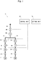
Fig. 1 is a schematic view illustrating an entire hot and cold water mixer according to an embodiment. -
Fig. 2 is a flowchart illustrating a flow of temperature control and flow rate control of the hot and cold water mixer according to the embodiment. -
Fig. 3 is a flowchart illustrating a flow of calculation of each target flow rate inFig. 2 . -
Fig. 4 is a flowchart illustrating a flow of sending a control signal to each flow rate adjustment valve inFig. 2 . - Next, a hot and cold water mixer according to an embodiment will be described with reference to the drawings. A hot and
cold water mixer 10 is installed in a kitchen or a bathroom. The hot andcold water mixer 10 supplies mixed water having a predetermined temperature and a predetermined flow rate to a sink or a discharge pipe attached to a washing place. As illustrated inFig. 1 , the hot andcold water mixer 10 includes a coldwater supply pipe 1C, a hotwater supply pipe 1H, and amixing pipe 1M. - The cold
water supply pipe 1C is connected to a cold water supply source C, and a cold water supply path is formed inside the coldwater supply pipe 1C. Cold water having a temperature of, for example, 20°C flows through the cold water supply path. The coldwater supply pipe 1C includes acheck valve 2C, a temperature sensor 3C, a flowrate adjustment valve 4C, and aflow rate sensor 5C in order from an upstream side to a downstream side. - The hot
water supply pipe 1H is connected to a hot water supply source H such as a gas water heater, and a hot water supply path is formed inside the hotwater supply pipe 1H. Hot water of, for example, 60°C flows through the hot water supply path. Similarly to the coldwater supply pipe 1C described above, the hotwater supply pipe 1H includes acheck valve 2H, atemperature sensor 3H, a flowrate adjustment valve 4H, and aflow rate sensor 5H in order from the upstream side to the downstream side. - The
mixing pipe 1M is connected to the coldwater supply pipe 1C and the hotwater supply pipe 1H, and a mixed water path is formed inside themixing pipe 1M. Mixed water obtained by mixing cold water supplied from the cold water supply path and hot water supplied from the hot water supply path flows through the mixed water path. Themixing pipe 1M includes atemperature sensor 3M and an on-offvalve 6M in order from the upstream side to the downstream side. The downstream side of themixing pipe 1M is connected to various discharge pipes (not illustrated). - The
temperature sensors Temperature sensors water supply pipe 1C, a temperature of hot water present in the hotwater supply pipe 1H, and a temperature of mixed water present in themixing pipe 1M, respectively. Thetemperature sensors 3C and 3H correspond to a part of the cold water-side information acquisition unit and the hot water-side information acquisition unit, respectively. - The flow
rate adjustment valves rate adjustment valves rate adjustment valves - The on-off
valve 6M is an electromagnetic valve. The on-offvalve 6M opens and closes a flow path of the mixed water path to flow or stop the mixed water in the mixed water path. - The
flow rate sensors flow rate sensors flow rate sensors - The hot and
cold water mixer 10 includes asetting unit 70 and acontrol unit 80. Thesetting unit 70 is a remote controller installed in a kitchen or a bathroom. Thesetting unit 70 includes various operation buttons (not illustrated) and a display panel that displays the temperature and the flow rate of mixed water present in the mixed water path. When the user inputs desired setting values of the temperature and the flow rate of the mixed water with the operation buttons, thesetting unit 70 sends setting information to thecontrol unit 80. - The
control unit 80 is connected to thetemperature sensors flow rate sensors rate adjustment valves valve 6M, and thesetting unit 70 in a wired manner. Thecontrol unit 80 receives and stores temperature information detected by each of thetemperature sensors 3C and 3H and flow rate information detected by each of theflow rate sensors flow rate sensor 5C correspond to cold water information. The temperature information detected by thetemperature sensor 3H and the flow rate information detected by theflow rate sensor 5H correspond to hot water information. In addition, thecontrol unit 80 stores an opening degree state of each of the flowrate adjustment valves valve 6M. Thecontrol unit 80 also stores in advance how much the opening degrees of the flowrate adjustment valves - When receiving setting information from the
setting unit 70 regarding discharge start or discharge stop, thecontrol unit 80 sends a control signal to the on-offvalve 6M to open and close the on-offvalve 6M. Thecontrol unit 80 calculates the target flow rates of cold water flowing through the cold water supply path and hot water flowing through the hot water supply path based on the setting information of thesetting unit 70, the temperature information of thetemperature sensors 3C and 3H, and the flow rate information of theflow rate sensors rate adjustment valves rate adjustment valves - The
control unit 80 controls the temperature and flow rate of mixed water present in the mixed water path as illustrated inFig. 2 . First, the control unit receives a set temperature TM and a set flow rate QM of the mixed water set from the setting unit (step S1). The set temperature TM and the set flow rate QM correspond to the setting information. Next, thecontrol unit 80 receives a temperature TC of cold water currently present in the cold water supply path and a temperature TH of hot water currently resent in the hot water supply path detected by thetemperature sensors 3C and 3H, respectively, and the flow rate QC of cold water currently present in the cold water supply path and the flow rate QH of hot water currently present in the hot water supply path detected by theflow rate sensors control unit 80 calculates a target flow rate QC1 of the cold water flowing through the cold water supply path and a target flow rate QH1 of the hot water flowing through the hot water supply path based on the setting information TM and QM, the current temperature information TC and TH, and the current flow rate information QC and QH (step S3). The flow rate QC of the cold water flowing through the cold water supply path is the same as the flow rate of cold water flowing through the flowrate adjustment valve 4C of the cold water supply path. The flow rate QH of the hot water flowing through the hot water supply path is the same as the flow rate of hot water flowing through the flowrate adjustment valve 4H of the hot water supply path. Details of this calculation method will be described later. - Next, based on the calculated target flow rates QC1 and QH1, the
control unit 80 determines adjustment amounts from the opening degrees of the flowrate adjustment valves control unit 80 determines the adjustment amounts of the flowrate adjustment valves control unit 80 sends control signals to the flowrate adjustment valves rate adjustment valves control unit 80 calculates again the target flow rates QC1 and QH1 based on the setting information TM and QM, the current temperature information TC and TH, and the current flow rate information QC and QH. Details of this calculation method will be described later. The number of repetitions of steps S1 to S5 may be set to a predetermined number or may be changed according to the setting information. When the number of repetitions from step S1 to step S5 is the last, thecontrol unit 80 determines the adjustment amounts of the flowrate adjustment valves - The
control unit 80 calculates the target flow rate QC1 for the flowrate adjustment valve 4C of the cold water supply path and the target flow rate QH1 for the flowrate adjustment valve 4H of the hot water supply path as illustrated inFig. 3 . First, thecontrol unit 80 determines whether the set temperature TM is lower than the temperature TH of hot water present in the hot water supply path (step S301). When it is determined in step S301 that the set temperature TM is higher than the temperature TH of the hot water present in the hot water supply path (when No is determined), thecontrol unit 80 calculates the target flow rate QC1 for the flowrate adjustment valve 4C to be 0 (step S302), calculates the target flow rate QH1 for the flowrate adjustment valve 4H to be the same as the set flow rate QM (step S303), and proceeds to step S4 of determining the adjustment amounts of the flowrate adjustment valves control unit 80 determines whether the set temperature TM is higher than the temperature TC of cold water present in the cold water supply path (step S304). When it is determined in step S304 that the set temperature TM is lower than the temperature TC of the cold water present in the cold water supply path (when No is determined), thecontrol unit 80 calculates the target flow rate QC1 for the flowrate adjustment valve 4C to be the same as the set flow rate QM (step S305), calculates the target flow rate QH1 for the flowrate adjustment valve 4H to be 0 (step S306), and proceeds to step S4 of determining the adjustment amounts of the flowrate adjustment valves - When it is determined in step S304 that the set temperature TM is equal to the cold water temperature TC or the set temperature TM is higher than the cold water temperature TC (when Yes is determined), the
control unit 80 calculates the target flow rate QC1 for the flowrate adjustment valve 4C according to the following Formula 1 (step S307) and calculates the target flow rate QH1 for the flowrate adjustment valve 4H according to the following Formula 2 (step S308).

- Next, the
control unit 80 determines whether the opening degree of the flowrate adjustment valve 4C is maximum and also determines whether the flow rate QC of the cold water currently present in the cold water supply path is lower than the target flow rate QC1 for the flowrate adjustment valve 4C (step S309). The case where the opening degree of the flowrate adjustment valve 4C is maximum is synonymous with the case where the flow rate QC of the cold water flowing through the cold water supply path cannot be increased. When it is determined in step S309 that the opening degree of the flowrate adjustment valve 4C is maximum and also that the cold water flow rate QC is lower than the target flow rate QC1 (when Yes is determined), thecontrol unit 80 calculates again and updates the target flow rate QH1 for the flowrate adjustment valve 4H according to the followingFormula 3 based on the flow rate QC of the cold water currently present in the cold water supply path (step S310).
- Then, the
control unit 80 proceeds to step S4 of determining the adjustment amounts of the flowrate adjustment valves rate adjustment valve 4C calculated in step S307 and the target flow rate QH1 for the flowrate adjustment valve 4H calculated again and updated in step S310. - When it is determined in step S309 that the opening degree of the flow
rate adjustment valve 4C is not maximum, or that the target flow rate QC1 is equal to the cold water flow rate QC or lower than the cold water flow rate QC (when No is determined), thecontrol unit 80 determines whether the opening degree of the flowrate adjustment valve 4H is maximum and also determines whether the flow rate QH of the hot water currently present in the hot water supply path is lower than the target flow rate QH1 for the flowrate adjustment valve 4H (step S311). The case where the opening degree of the flowrate adjustment valve 4H is maximum is synonymous with the case where the flow rate QH of the hot water flowing through the hot water supply path cannot be increased. When it is determined in step S311 that the opening degree of the flowrate adjustment valve 4H is maximum and also that the hot water flow rate QH is lower than the target flow rate QH1 (when Yes is determined), thecontrol unit 80 calculates again and updates the target flow rate QC1 for the flowrate adjustment valve 4C according to the followingFormula 4 based on the flow rate QH of the hot water currently present in the hot water supply path (step S312).
- Then, the
control unit 80 proceeds to step S4 of determining the adjustment amounts of the flowrate adjustment valves rate adjustment valve 4H is not maximum, or that the target flow rate QH1 is equal to the hot water flow rate QH or lower than the hot water flow rate QH (when No is determined), the flowrate adjustment valves control unit 80 does not update the target flow rate QC1 or QH1, and proceeds to step S4 of determining the adjustment amounts of the flowrate adjustment valves - In step S5, the
control unit 80 calculates again the target flow rate QC1 for the flowrate adjustment valve 4C or the target flow rate QH1 for the flowrate adjustment valve 4H as illustrated inFig. 4 . First, thecontrol unit 80 sends a control signal to the flowrate adjustment valve 4C, and drives the flowrate adjustment valve 4C by the adjustment amount of the flowrate adjustment valve 4C determined in step S4 (step S501). Next, thecontrol unit 80 determines whether the opening degree of the flowrate adjustment valve 4C is maximum and also determines whether the flow rate QC of the cold water currently present in the cold water supply path is lower than the target flow rate QC1 for the flowrate adjustment valve 4C (step S502). When it is determined in step S502 that the opening degree of the flowrate adjustment valve 4C is maximum and also that the cold water flow rate QC is lower than the target flow rate QC1 for the flowrate adjustment valve 4C (when Yes is determined), thecontrol unit 80 calculates again and updates the target flow rate QH1 for the hot water supply path according to the followingFormula 5 based on the flow rate QC of the cold water currently present in the cold water supply path (step S503).
- Next, the
control unit 80 determines again and updates the adjustment amount of the flowrate adjustment valve 4H determined in step S4 based on the target flow rate QH1 calculated again in step S503 (step S504). Then, thecontrol unit 80 sends a control signal to the flowrate adjustment valve 4H, and drives the flowrate adjustment valve 4H by the adjustment amount of the flowrate adjustment valve 4H determined in step S504 (step S505). When it is determined in step S502 that the opening degree of the flowrate adjustment valve 4C is not maximum, or that the target flow rate QC1 is equal to the cold water flow rate QC or lower than the cold water flow rate QC (when No is determined), the flowrate adjustment valve 4C can increase the opening degree. In this case, thecontrol unit 80 proceeds to step S505 without executing step S503 and S504. In this case, the adjustment amount of the flowrate adjustment valve 4H remains the adjustment amount determined in step S4. - Next, the
control unit 80 determines whether the opening degree of the flowrate adjustment valve 4H is maximum and also determines whether the flow rate QH of the hot water currently present in the hot water supply path is lower than the target flow rate QH1 for the flowrate adjustment valve 4H (step S506). When it is determined in step S506 that the opening degree of the flowrate adjustment valve 4H is maximum and also that the hot water flow rate QH is lower than the target flow rate QH1 (when Yes is determined), thecontrol unit 80 calculates again and updates the target flow rate QC1 for the flowrate adjustment valve 4C according to the following Formula 6 based on the flow rate QH of the hot water currently present in the hot water supply path (step S507).
- Next, the
control unit 80 determines again and updates the adjustment amount of the flowrate adjustment valve 4C in the cold water supply path determined in step S4 based on the target flow rate QC1 for the flowrate adjustment valve 4C calculated again in step S507 (step S508). Then, thecontrol unit 80 sends a control signal to the flowrate adjustment valve 4C, and drives the flowrate adjustment valve 4C by the adjustment amount of the flowrate adjustment valve 4C determined in step S508 (step S509). When it is determined in step S506 that the opening degree of the flowrate adjustment valve 4H is not maximum, or that the target flow rate QH1 is equal to the hot water flow rate QH or lower than the hot water flow rate QH (when No is determined), the flowrate adjustment valve 4H can increase the opening degree. In this case, thecontrol unit 80 proceeds to step S509 without executing step S507 and S508. In this case, the adjustment amount of the flowrate adjustment valve 4C in the cold water supply path remains the adjustment amount determined in step S4. - Next, the action and effect of the present embodiment will be described. The hot and
cold water mixer 10 according to the present embodiment includes a coldwater supply pipe 1C connected to a cold water supply source C and having a cold water supply path formed therein through which cold water supplied from the cold water supply source C flows; a hotwater supply pipe 1H connected to a hot water supply source H and having a hot water supply path formed therein through which hot water supplied from the hot water supply source H flows; and a mixingpipe 1M connected to the coldwater supply pipe 1C and the hotwater supply pipe 1H and having a mixed water path formed therein through which mixed water obtained by mixing cold water supplied from the cold water supply path and hot water supplied from the hot water supply path flows. The hot andcold water mixer 10 further includes a flowrate adjustment valve 4C which adjusts a flow rate of cold water preset in the cold water supply path, and a temperature sensor 3C and aflow rate sensor 5C which detect a temperature and a flow rate, respectively, of the cold water present in the cold water supply path. The hot andcold water mixer 10 further includes a flowrate adjustment valve 4H which adjusts a flow rate of hot water preset in the hot water supply path, and atemperature sensor 3H and aflow rate sensor 5C which detect a temperature and a flow rate, respectively, of the hot water present in the hot water supply path. The hot andcold water mixer 10 further includes asetting unit 70 which sets a temperature and a flow rate of mixed water present in the mixed water path, and acontrol unit 80 which controls the flowrate adjustment valves control unit 80 of the hot andcold water mixer 10 calculates a target flow rate QC1 for the flowrate adjustment valve 4C and a target flow rate QH1 for the flowrate adjustment valve 4H based on a set temperature TM and a set flow rate QM of thesetting unit 70, a temperature TC of the cold water present in the cold water supply path acquired from the temperature sensor 3C, and a temperature TH of the hot water present in the hot water supply path acquired from thetemperature sensor 3H, and determines and controls adjustment amounts of the flowrate adjustment valves cold water mixer 10 can supply mixed water having a temperature and a flow rate desired by the user. - When the control unit 80 of the hot and cold water mixer 10 determines that the flow rate adjustment valve 4C cannot increase the flow rate and also determines, by comparing the target flow rate QC1 for flow rate adjustment valve 4C with the flow rate QC of the cold water flowing through the cold water supply path, that the target flow rate QC1 is higher, the control unit 80 calculates and updates the target flow rate QH1 of the flow rate adjustment valve 4H based on the flow rate QC of the cold water currently flowing through the cold water supply path so that the temperature TM of the mixed water set by the setting unit 70 can be attained, and controls the flow rate adjustment valve 4H based on the updated target flow rate QH1. Further, when the control unit 80 determines that the flow rate adjustment valve 4H cannot increase the flow rate and also determines, by comparing the target flow rate QH1 of flow rate adjustment valve 4H with the flow rate QH of the hot water flowing through the hot water supply path, that the target flow rate QH1 is higher, the control unit 80 calculates and updates the target flow rate QC1 for the flow rate adjustment valve 4C based on the flow rate QH of the hot water currently flowing through the hot water supply path so that the temperature TM of the mixed water set by the setting unit 70 can be attained, and controls the flow rate adjustment valve 4C based on the updated target flow rate QC1. When there is a pressure fluctuation such as a pressure of the cold water supply source C and a pressure of the hot water supply source H being lower than predetermined pressures or the differential pressures being large, the flow rates cannot be increased to the target flow rates even if opening degrees of the flow rate adjustment valves 4C and 4H are maximized. The hot and
cold water mixer 10, however, prioritizes the set temperature TM over the set flow rate QM of the mixed water, and updates the target flow rates to control the flowrate adjustment valves cold water mixer 10 can perform stable temperature control. - Further, the
control unit 80 of the hot andcold water mixer 10 stores the opening degrees of the flowrate adjustment valves cold water mixer 10 can rapidly determine that the flow rates cannot be increased, without driving the flowrate adjustment valves flow rate sensors cold water mixer 10 can perform more stable temperature control. - The present disclosure is not limited to the embodiment explained with reference to the above description and drawings, and the following embodiments are also included in the technical scope of the present invention.
- (1) The hot and
cold water mixer 10 of the present embodiment includes the on-offvalve 6M in the mixingpipe 1M, but the mixingpipe 1M may have no on-off valve. In this case, the coldwater supply pipe 1C and the hotwater supply pipe 1H may have an on-off valve, or the flowrate adjustment valves - (2) The cold
water supply pipe 1C and the hotwater supply pipe 1H of the present embodiment have theflow rate sensors flow rate sensors pipe 1M may have a flow rate sensor. For example, when theflow rate sensor 5H is not provided in the hotwater supply pipe 1H, the flow rate QH of the hot water in the hot water supply path is calculated by subtracting the cold water flow rate QC detected by theflow rate sensor 5C of the coldwater supply pipe 1C from the mixed water flow rate detected by the flow rate sensor in the mixingpipe 1M. - (3) The
control unit 80 of the present embodiment is connected to theflow rate sensors unit 70, and the like in a wired manner, but may be electrically connected to a part or all of them in a wireless manner. - (4) The
control unit 80 of the present embodiment stores the opening degrees of the flowrate adjustment valves control unit 80 may drive the flowrate adjustment valves flow rate sensors rate adjustment valves -
- 10 Hot and cold water mixer
- 1C Cold water supply pipe (cold water supply path)
- 1H Hot water supply pipe (hot water supply path)
- 1M Mixing pipe (mixed water path)
- 3C Temperature sensor (part of cold water-side information acquisition unit)
- 3H Temperature sensor (part of hot water-side information acquisition unit)
- 4C Flow rate adjustment valve (cold water-side flow rate adjustment unit)
- 4H Flow rate adjustment valve (hot water-side flow rate adjustment unit)
- 5C Flow rate sensor (part of cold water-side information acquisition unit)
- 5H Flow rate sensor (part of hot water-side information acquisition unit)
- 70 Setting unit
- 80 Control unit
- QM Set flow rate (part of setting information)
- TM Set temperature (part of setting information)
- QC Flow rate of cold water in cold water supply path (part of cold water information)
- TC Temperature of cold water in cold water supply path (part of cold water information)
- QH Flow rate of hot water in hot water supply path (part of hot water information)
- TH Temperature of hot water in hot water supply path (part of hot water information)
- QC1 Target flow rate of cold water flowing through cold water supply path
- QH1 Target flow rate of hot water flowing through hot water supply path
Claims (2)
- A hot and cold water mixer comprising:a cold water supply path connected to a cold water supply source and through which cold water supplied from the cold water supply source flows;a hot water supply path connected to a hot water supply source and through which hot water supplied from the hot water supply source flows;a mixed water path that is connected to the cold water supply path and the hot water supply path and through which mixed water obtained by mixing cold water supplied from the cold water supply path and hot water supplied from the hot water supply path flows;a cold water-side flow rate adjustment unit that adjusts a flow rate of cold water present in the cold water supply path;a hot water-side flow rate adjustment unit that adjusts a flow rate of hot water present in the hot water supply path;a cold water-side information acquisition unit configured to acquire cold water information including a temperature and the flow rate of the cold water present in the cold water supply path;a hot water-side information acquisition unit configured to acquire hot water information including a temperature and the flow rate of the hot water present in the hot water supply path;a setting unit configured to set a temperature and a flow rate of mixed water present in the mixed water path; anda control unit that calculates a target flow rate of cold water flowing through the cold water supply path and a target flow rate of hot water flowing through the hot water supply path based on setting information of the setting unit, the cold water information of the cold water-side information acquisition unit, and the hot water information of the hot water-side information acquisition unit, and controls the cold water-side flow rate adjustment unit and the hot water-side flow rate adjustment unit,wherein, when the control unit determines that at least either one of the cold water-side flow rate adjustment unit and the hot-water side flow rate adjustment unit cannot increase the flow rate, and also determines, by comparing the target flow rate for the one flow rate adjustment unit with the flow rate of water flowing through the one flow rate adjustment unit, that the target flow rate for the one flow rate adjustment unit is higher, the control unit calculates and updates the target flow rate for the other flow rate adjustment unit so that the temperature of the mixed water set by the setting unit can be attained, and controls the other flow rate adjustment unit based on the updated target flow rate for the other flow rate adjustment unit.
- The hot and cold water mixer according to claim 1, wherein the control unit stores each of opening degrees of the cold water-side flow rate adjustment unit and the hot water-side flow rate adjustment unit, and determines that the flow rates cannot be increased.
Applications Claiming Priority (2)
| Application Number | Priority Date | Filing Date | Title |
|---|---|---|---|
| JP2019175482A JP7296290B2 (en) | 2019-09-26 | 2019-09-26 | hot water mixer |
| PCT/JP2020/022154 WO2021059599A1 (en) | 2019-09-26 | 2020-06-04 | Hot and cold water mixer |
Publications (2)
| Publication Number | Publication Date |
|---|---|
| EP4036328A1 true EP4036328A1 (en) | 2022-08-03 |
| EP4036328A4 EP4036328A4 (en) | 2023-11-01 |
Family
ID=75157214
Family Applications (1)
| Application Number | Title | Priority Date | Filing Date |
|---|---|---|---|
| EP20870377.7A Withdrawn EP4036328A4 (en) | 2019-09-26 | 2020-06-04 | Hot and cold water mixer |
Country Status (5)
| Country | Link |
|---|---|
| US (1) | US20220397921A1 (en) |
| EP (1) | EP4036328A4 (en) |
| JP (1) | JP7296290B2 (en) |
| CN (1) | CN114450537A (en) |
| WO (1) | WO2021059599A1 (en) |
Family Cites Families (17)
| Publication number | Priority date | Publication date | Assignee | Title |
|---|---|---|---|---|
| JP2532536B2 (en) * | 1987-12-17 | 1996-09-11 | 松下電器産業株式会社 | Hot water mixing controller |
| JP2513268B2 (en) * | 1988-03-23 | 1996-07-03 | 株式会社ノーリツ | Hot water mixing device |
| GB9010842D0 (en) * | 1990-05-15 | 1990-07-04 | Computer Shower Company The Li | Fluid flow and temperature control apparatus |
| JPH0759989B2 (en) * | 1990-06-29 | 1995-06-28 | 株式会社ノーリツ | Water heater |
| JP3466598B2 (en) * | 2002-04-18 | 2003-11-10 | 株式会社アルボ | Control device in fluid mixing device |
| GB2428281A (en) * | 2005-07-12 | 2007-01-24 | Alexander Terrell | Electronic mixer valve control |
| JP5782631B2 (en) * | 2011-09-29 | 2015-09-24 | 株式会社Lixil | Mixer tap |
| JP6304623B2 (en) * | 2014-02-12 | 2018-04-04 | パナソニックIpマネジメント株式会社 | Hot water mixing device |
| JP6376331B2 (en) | 2014-03-26 | 2018-08-22 | Toto株式会社 | Hot water mixing device |
| JP6138718B2 (en) * | 2014-03-28 | 2017-05-31 | 株式会社Lixil | Control unit for mixed faucet and temperature control device for mixed faucet |
| JP2016217641A (en) * | 2015-05-21 | 2016-12-22 | パナソニックIpマネジメント株式会社 | Hot water mixing device |
| JP6953760B2 (en) * | 2017-03-28 | 2021-10-27 | 株式会社ノーリツ | Replenishment water device |
| CN108662785A (en) * | 2017-03-31 | 2018-10-16 | 芜湖美的厨卫电器制造有限公司 | Water-heater system and its control method |
| CN108799610A (en) * | 2017-04-28 | 2018-11-13 | 青岛经济技术开发区海尔热水器有限公司 | Constant-temperature constant-flow water outlet control method and constant-temperature constant-flow valve |
| CN109062287A (en) * | 2018-06-25 | 2018-12-21 | 厦门建霖健康家居股份有限公司 | A kind of outlet controlling system and method |
| JP7003885B2 (en) * | 2018-09-18 | 2022-02-04 | 横浜ゴム株式会社 | Aircraft hot water supply system |
| US11280424B2 (en) * | 2019-06-03 | 2022-03-22 | Johnson Controls Tyco IP Holdings LLP | Failsafe system for a 270 degree actuator |
-
2019
- 2019-09-26 JP JP2019175482A patent/JP7296290B2/en active Active
-
2020
- 2020-06-04 US US17/764,052 patent/US20220397921A1/en not_active Abandoned
- 2020-06-04 CN CN202080067679.XA patent/CN114450537A/en active Pending
- 2020-06-04 WO PCT/JP2020/022154 patent/WO2021059599A1/en not_active Ceased
- 2020-06-04 EP EP20870377.7A patent/EP4036328A4/en not_active Withdrawn
Also Published As
| Publication number | Publication date |
|---|---|
| CN114450537A (en) | 2022-05-06 |
| EP4036328A4 (en) | 2023-11-01 |
| JP7296290B2 (en) | 2023-06-22 |
| WO2021059599A1 (en) | 2021-04-01 |
| US20220397921A1 (en) | 2022-12-15 |
| JP2021050578A (en) | 2021-04-01 |
Similar Documents
| Publication | Publication Date | Title |
|---|---|---|
| EP3483690B1 (en) | A method for controlling a fluid flow through a valve | |
| EP2641027B1 (en) | Device and method for controlling opening of a valve in an hvac system | |
| US20090139466A1 (en) | Hot water apparatus | |
| EP3106764B1 (en) | Hot and cold water mixing device | |
| US11713564B2 (en) | Faucet control device and method, and faucet | |
| JPH11202945A (en) | Self-diagnosing method for mass flow controller | |
| EP3364116A1 (en) | Method for controlling a heat pump and heat pump | |
| US9671120B2 (en) | Thermal source instrument controlling device and air-conditioning system | |
| US20240360654A1 (en) | Device and method for controlling faucet, and faucet | |
| JP2022035780A (en) | Flow rate control device and method, and fluid supply system | |
| CN110425744B (en) | Wind pressure control system and control method for full-premix gas heating water heater | |
| JP2012195632A (en) | Device for generating operation condition data | |
| JP7296290B2 (en) | hot water mixer | |
| KR101709534B1 (en) | Combustion apparatus capable of measuring of gas amount used and the measuring method of gas amount | |
| JP5243843B2 (en) | Combustion equipment and abnormality diagnosis method for combustion equipment | |
| JP7296289B2 (en) | hot water mixer | |
| JPH0875223A (en) | Air conditioning control system | |
| WO2022201607A1 (en) | Hot and cold water mixer | |
| JP6187911B2 (en) | Water discharge device | |
| JP6376331B2 (en) | Hot water mixing device | |
| JP5414648B2 (en) | Combined combustion device | |
| KR101785247B1 (en) | Automatic hot-water control apparatus and control method therefor | |
| JP2009250471A (en) | Hot water supply device | |
| JP2010231331A (en) | Water volume management system | |
| JP2025167024A (en) | hot water mixing device |
Legal Events
| Date | Code | Title | Description |
|---|---|---|---|
| STAA | Information on the status of an ep patent application or granted ep patent |
Free format text: STATUS: THE INTERNATIONAL PUBLICATION HAS BEEN MADE |
|
| PUAI | Public reference made under article 153(3) epc to a published international application that has entered the european phase |
Free format text: ORIGINAL CODE: 0009012 |
|
| STAA | Information on the status of an ep patent application or granted ep patent |
Free format text: STATUS: REQUEST FOR EXAMINATION WAS MADE |
|
| 17P | Request for examination filed |
Effective date: 20220224 |
|
| AK | Designated contracting states |
Kind code of ref document: A1 Designated state(s): AL AT BE BG CH CY CZ DE DK EE ES FI FR GB GR HR HU IE IS IT LI LT LU LV MC MK MT NL NO PL PT RO RS SE SI SK SM TR |
|
| DAV | Request for validation of the european patent (deleted) | ||
| DAX | Request for extension of the european patent (deleted) | ||
| RAP3 | Party data changed (applicant data changed or rights of an application transferred) |
Owner name: LIXIL CORPORATION |
|
| RIN1 | Information on inventor provided before grant (corrected) |
Inventor name: NAGATA, MASAAKI Inventor name: KAMATA, AZUMI Inventor name: OZEKI, KENJI Inventor name: MIZUNO, TAKAYUKI |
|
| REG | Reference to a national code |
Ref country code: DE Ref legal event code: R079 Free format text: PREVIOUS MAIN CLASS: E03C0001044000 Ipc: F24D0017000000 |
|
| A4 | Supplementary search report drawn up and despatched |
Effective date: 20231004 |
|
| RIC1 | Information provided on ipc code assigned before grant |
Ipc: F24H 15/315 20220101ALI20230927BHEP Ipc: F24D 19/10 20060101ALI20230927BHEP Ipc: G05D 23/13 20060101ALI20230927BHEP Ipc: F24D 17/00 20220101AFI20230927BHEP |
|
| STAA | Information on the status of an ep patent application or granted ep patent |
Free format text: STATUS: THE APPLICATION IS DEEMED TO BE WITHDRAWN |
|
| 18D | Application deemed to be withdrawn |
Effective date: 20240504 |