EP4036309A1 - Backpack blower work apparatus - Google Patents
Backpack blower work apparatus Download PDFInfo
- Publication number
- EP4036309A1 EP4036309A1 EP20871748.8A EP20871748A EP4036309A1 EP 4036309 A1 EP4036309 A1 EP 4036309A1 EP 20871748 A EP20871748 A EP 20871748A EP 4036309 A1 EP4036309 A1 EP 4036309A1
- Authority
- EP
- European Patent Office
- Prior art keywords
- working machine
- back frame
- lower section
- backpack blower
- blower working
- Prior art date
- Legal status (The legal status is an assumption and is not a legal conclusion. Google has not performed a legal analysis and makes no representation as to the accuracy of the status listed.)
- Pending
Links
Images


Classifications
-
- A—HUMAN NECESSITIES
- A01—AGRICULTURE; FORESTRY; ANIMAL HUSBANDRY; HUNTING; TRAPPING; FISHING
- A01G—HORTICULTURE; CULTIVATION OF VEGETABLES, FLOWERS, RICE, FRUIT, VINES, HOPS OR SEAWEED; FORESTRY; WATERING
- A01G20/00—Cultivation of turf, lawn or the like; Apparatus or methods therefor
- A01G20/40—Apparatus for cleaning the lawn or grass surface
- A01G20/43—Apparatus for cleaning the lawn or grass surface for sweeping, collecting or disintegrating lawn debris
- A01G20/47—Vacuum or blower devices
-
- E—FIXED CONSTRUCTIONS
- E01—CONSTRUCTION OF ROADS, RAILWAYS, OR BRIDGES
- E01H—STREET CLEANING; CLEANING OF PERMANENT WAYS; CLEANING BEACHES; DISPERSING OR PREVENTING FOG IN GENERAL CLEANING STREET OR RAILWAY FURNITURE OR TUNNEL WALLS
- E01H1/00—Removing undesirable matter from roads or like surfaces, with or without moistening of the surface
- E01H1/08—Pneumatically dislodging or taking-up undesirable matter or small objects; Drying by heat only or by streams of gas; Cleaning by projecting abrasive particles
- E01H1/0809—Loosening or dislodging by blowing ; Drying by means of gas streams
-
- F—MECHANICAL ENGINEERING; LIGHTING; HEATING; WEAPONS; BLASTING
- F04—POSITIVE - DISPLACEMENT MACHINES FOR LIQUIDS; PUMPS FOR LIQUIDS OR ELASTIC FLUIDS
- F04D—NON-POSITIVE-DISPLACEMENT PUMPS
- F04D25/00—Pumping installations or systems
- F04D25/02—Units comprising pumps and their driving means
- F04D25/06—Units comprising pumps and their driving means the pump being electrically driven
- F04D25/0673—Battery powered
-
- F—MECHANICAL ENGINEERING; LIGHTING; HEATING; WEAPONS; BLASTING
- F04—POSITIVE - DISPLACEMENT MACHINES FOR LIQUIDS; PUMPS FOR LIQUIDS OR ELASTIC FLUIDS
- F04D—NON-POSITIVE-DISPLACEMENT PUMPS
- F04D25/00—Pumping installations or systems
- F04D25/02—Units comprising pumps and their driving means
- F04D25/08—Units comprising pumps and their driving means the working fluid being air, e.g. for ventilation
- F04D25/084—Units comprising pumps and their driving means the working fluid being air, e.g. for ventilation hand fans
-
- F—MECHANICAL ENGINEERING; LIGHTING; HEATING; WEAPONS; BLASTING
- F04—POSITIVE - DISPLACEMENT MACHINES FOR LIQUIDS; PUMPS FOR LIQUIDS OR ELASTIC FLUIDS
- F04D—NON-POSITIVE-DISPLACEMENT PUMPS
- F04D29/00—Details, component parts, or accessories
- F04D29/40—Casings; Connections of working fluid
- F04D29/42—Casings; Connections of working fluid for radial or helico-centrifugal pumps
- F04D29/4206—Casings; Connections of working fluid for radial or helico-centrifugal pumps especially adapted for elastic fluid pumps
- F04D29/4226—Fan casings
-
- F—MECHANICAL ENGINEERING; LIGHTING; HEATING; WEAPONS; BLASTING
- F04—POSITIVE - DISPLACEMENT MACHINES FOR LIQUIDS; PUMPS FOR LIQUIDS OR ELASTIC FLUIDS
- F04D—NON-POSITIVE-DISPLACEMENT PUMPS
- F04D29/00—Details, component parts, or accessories
- F04D29/60—Mounting; Assembling; Disassembling
- F04D29/601—Mounting; Assembling; Disassembling specially adapted for elastic fluid pumps
-
- F—MECHANICAL ENGINEERING; LIGHTING; HEATING; WEAPONS; BLASTING
- F04—POSITIVE - DISPLACEMENT MACHINES FOR LIQUIDS; PUMPS FOR LIQUIDS OR ELASTIC FLUIDS
- F04D—NON-POSITIVE-DISPLACEMENT PUMPS
- F04D29/00—Details, component parts, or accessories
- F04D29/60—Mounting; Assembling; Disassembling
- F04D29/62—Mounting; Assembling; Disassembling of radial or helico-centrifugal pumps
- F04D29/624—Mounting; Assembling; Disassembling of radial or helico-centrifugal pumps especially adapted for elastic fluid pumps
-
- H—ELECTRICITY
- H01—ELECTRIC ELEMENTS
- H01M—PROCESSES OR MEANS, e.g. BATTERIES, FOR THE DIRECT CONVERSION OF CHEMICAL ENERGY INTO ELECTRICAL ENERGY
- H01M50/00—Constructional details or processes of manufacture of the non-active parts of electrochemical cells other than fuel cells, e.g. hybrid cells
- H01M50/20—Mountings; Secondary casings or frames; Racks, modules or packs; Suspension devices; Shock absorbers; Transport or carrying devices; Holders
-
- Y—GENERAL TAGGING OF NEW TECHNOLOGICAL DEVELOPMENTS; GENERAL TAGGING OF CROSS-SECTIONAL TECHNOLOGIES SPANNING OVER SEVERAL SECTIONS OF THE IPC; TECHNICAL SUBJECTS COVERED BY FORMER USPC CROSS-REFERENCE ART COLLECTIONS [XRACs] AND DIGESTS
- Y02—TECHNOLOGIES OR APPLICATIONS FOR MITIGATION OR ADAPTATION AGAINST CLIMATE CHANGE
- Y02E—REDUCTION OF GREENHOUSE GAS [GHG] EMISSIONS, RELATED TO ENERGY GENERATION, TRANSMISSION OR DISTRIBUTION
- Y02E60/00—Enabling technologies; Technologies with a potential or indirect contribution to GHG emissions mitigation
- Y02E60/10—Energy storage using batteries
Definitions
- the present invention relates to a backpack blower working machine.
- a backpack blower working machine including a backpack frame configured to be carried on the back of a worker by shoulder straps, a volute case mounted on the backpack frame, a centrifugal fan rotatably supported in the volute case, an electric motor assembled to the volute case and configured to rotate the centrifugal fan, and a battery pack detachably attached to the backpack frame and configured to supply the electric motor with electricity (see Patent Literature 1).
- the conventional backpack blower working machine has a problem that the backpack frame including the electric motor and the battery pack which are heavy components is worn on the worker only by the shoulder straps, and therefore, when the work is continued for a long time, a heavy load is applied intensively to the shoulders, and consequently the fatigue of the shoulders is increased.
- the conventional backpack blower working machine has a problem that the backpack frame may be forced to move in the direction to separate from the back of the worker due to the reactive force of the blow pressure during the work, and by this means, the load applied to the shoulders is increased, and consequently the fatigue of the shoulders is increased.
- the conventional backpack blower working machine has a problem that the worker holds on so as not to fall down backward (in the direction to turn to the back side from the waist or the legs) to oppose to the reactive force of the blow pressure and the gravity of the heavy components mounted on the back as described above, and therefore the strain on the waist and the legs is increased.
- the present invention has been proposed to address the above-described problems. It is therefore an object of the invention to provide a backpack blower working machine capable of reducing the strain on the shoulders, the waist and the legs during the work to reduce the fatigue of the shoulders, the waist and the legs, and mounting a large battery to continue the work for a long time.
- the invention provides a backpack blower working machine including: a back frame worn to be carried on a back of a worker; a volute case mounted on the back frame; a centrifugal fan equipped in the volute case; an electric motor assembled to the volute case and configured to rotate the centrifugal fan; and a battery attached to the back frame and configured to supply the electric motor with electricity.
- the back frame includes an upper section and a lower section. Shoulder belts for carrying and the volute case are provided on the upper section.
- a battery arrangement space for the battery is provided in the lower section, and has a length in an up-and-down direction and a length in a right and left direction each of which is longer than a length in a front-to-back direction.
- the lower section of the back frame even though a large battery is mounted, it is possible to support the lower section of the back frame by the waist, and therefore to reduce the strain on the shoulders, the waist and the legs during the work.
- the lower section of the back frame having a high ratio of the weight distribution is supported by the waist.
- a backpack blower working machine 1 includes a back frame 2, a volute case 3 mounted on the back frame 2, a centrifugal fan 30 equipped in the volute case 3, an electric motor 4 assembled to the volute case 3 and configured to rotate the centrifugal fan 30, and batteries 5 attached to the back frame 2 and configured to supply the electric motor 4 with electricity.
- a blower tube 31 is connected to a blowing outlet 3A of the volute case 3.
- a worker M carrying the backpack blower working machine 1 on the back operates the blower tube 31 by the hand to perform blowing work such as cleaning of fallen leaves.
- the back frame 2 is a frame worn to be carried on the back of a worker, and includes an upper section 2A and a lower section 2B.
- the front side of each of the upper section 2A and the lower section 2B is formed as a back pad 20, and a handle 21 is provided on the top of the upper section 2A.
- the upper section 2A and the lower section 2B are formed as individual parts, and coupled to one another at a coupling part 2C.
- the volute case 3 is mounted on the upper section 2A of the back frame 2.
- the centrifugal fan 30 is equipped in the volute case 3, and the electric motor 4 configured to rotate the centrifugal fan 30 is supported on the upper section 2A.
- the electric motor 4 is provided on the back surface side of the above-described back pad 20, and the centrifugal fan 30 is disposed backward of the electric motor 4.
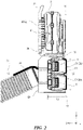
- the electric motor 4 having a heavy weight is disposed on the back frame 2 side, and therefore a center of gravity G1 of the components mounted on the upper section 2A is located near the back frame 2 as illustrated in Fig. 2 .
- the lower section 2B of the back frame 2 includes a battery arrangement space in which the above-described batteries 5 are mounted.
- a battery holder 50 is supported in the battery arrangement space of the lower section 2B, and slidably holds the batteries 5 in the longitudinal direction.
- the battery holder 50 includes a plurality of battery holders 51 and 52 to arrange the plurality of batteries 5 vertically with the longitudinal direction of the plurality of batteries 5 facing horizontally.
- the entire battery arrangement space has a length L1 along the front-to-back direction (the X direction in the drawing) and a length L2 along the up-and-down direction (the Z direction in the drawing) as illustrated in Fig. 2 , and has a length L3 along the right and left direction (the Y direction in the drawing). Moreover, each of the length L2 in the up-and-down direction and the length L3 in the right and left direction of the battery arrangement space is longer than the length L1 in the front-to-back direction.
- the plurality of batteries 5 are provided in the lower section 2B of the back frame 2.
- the weight of the components (the batteries 5 and the battery holder 50) provided in the back frame 2B is greater than the weight of the components (the volute case 3, the centrifugal fan 30, and the electric motor 4) provided in the upper section 2A of the back frame 2.
- the position of T2 in Fig. 2 is at the same level as or more backward than that of T1 in Fig. 2 .
- the center of gravity G1 of the components mounted on the upper section 2A of the back frame 2 is located more forward (toward the X direction in the drawing) than a center of gravity G2 of the components mounted on the lower section 2B.
- This backpack blower working machine 1 includes shoulder belts 6 for carrying which are provided on the upper section 2A of the back frame 2 as illustrated in Fig. 5 .
- the shoulder belts 6 are worn around the shoulders of the worker M to carry the back frame 2 on the back.
- the back frame 2 is supported to turn around the shoulders of the worker M to move the lower section 2B forward, due to the weight distribution of the components mounted on the upper section 2A and the components mounted on the lower section 2B of the back frame 2. Therefore, the lower section 2B is maintained to be close to the body of the worker M during the work.
- the strain on the shoulders of the worker M is dispersed around the waist of the worker M, and therefore the strain on the shoulders, the waist, and the legs is reduced.
- each of the length L2 in the up-and-down direction and the length L3 in the right and left direction of the battery arrangement space for the batteries 5 mounted on the lower section 2B is longer than the length L1 in the front-to-back direction. Therefore, the batteries 5 having a heavy weight are supported around the waist in a relatively large area, and consequently the back frame 2 can be stably carried on the back.
- a waist belt 7 to be wrapped around the waist is provided on the lower section 2B, and the waist is wrapped by the waist belt 7.
- the upper section 2A and the lower section 2B are coupled to one another at the coupling part 2C, and more preferred that the coupling part 2C is flexible.
- the upper section 2A and the lower section 2B are formed as individual parts and coupled to one another, and therefore the lower section 2B having a high ratio of the weight distribution can be separated from the upper section 2A and fixed to around the waist of the worker M. By this means, even when the upper section 2A is moved by the reactive force of the blow pressure during the work, the lower section 2B of the back frame 2 having a high ratio of the weight distribution is supported around the waist.
- the upper section 2A and the lower section 2B are coupled to one another during the work, but may be separated from one another when the work is not performed.
- this backpack blower working machine 1 includes the large batteries 5 having a heavy weight
- the back frame 2 can be more stably carried on the back thanks to this heavy weight, and therefore it is possible to reduce the strain on the worker. Therefore, it is possible to dispose the plurality of large batteries 5 to continue the work of the backpack blower working machine 1 for a long time.
- the plurality of batteries 5 are arranged vertically with the longitudinal direction of the plurality of batteries 5 facing horizontally, and therefore the plurality of batteries 5 are close to the body and supported around the waist in a large area.
Landscapes
- Engineering & Computer Science (AREA)
- Mechanical Engineering (AREA)
- General Engineering & Computer Science (AREA)
- Life Sciences & Earth Sciences (AREA)
- Environmental Sciences (AREA)
- Architecture (AREA)
- Civil Engineering (AREA)
- Structural Engineering (AREA)
- Chemical Kinetics & Catalysis (AREA)
- Electrochemistry (AREA)
- General Chemical & Material Sciences (AREA)
- Chemical & Material Sciences (AREA)
- Structures Of Non-Positive Displacement Pumps (AREA)
- Cleaning Of Streets, Tracks, Or Beaches (AREA)
- Battery Mounting, Suspending (AREA)
Abstract
Description
- The present invention relates to a backpack blower working machine.
- Conventionally, there has been known a backpack blower working machine including a backpack frame configured to be carried on the back of a worker by shoulder straps, a volute case mounted on the backpack frame, a centrifugal fan rotatably supported in the volute case, an electric motor assembled to the volute case and configured to rotate the centrifugal fan, and a battery pack detachably attached to the backpack frame and configured to supply the electric motor with electricity (see Patent Literature 1).
- PTL1:
Japanese Patent Application Laid-Open No. 2016-204931 - The conventional backpack blower working machine has a problem that the backpack frame including the electric motor and the battery pack which are heavy components is worn on the worker only by the shoulder straps, and therefore, when the work is continued for a long time, a heavy load is applied intensively to the shoulders, and consequently the fatigue of the shoulders is increased.
- In addition, the conventional backpack blower working machine has a problem that the backpack frame may be forced to move in the direction to separate from the back of the worker due to the reactive force of the blow pressure during the work, and by this means, the load applied to the shoulders is increased, and consequently the fatigue of the shoulders is increased. Moreover, the conventional backpack blower working machine has a problem that the worker holds on so as not to fall down backward (in the direction to turn to the back side from the waist or the legs) to oppose to the reactive force of the blow pressure and the gravity of the heavy components mounted on the back as described above, and therefore the strain on the waist and the legs is increased.
- Here, in order to prevent the strain on the shoulders, the waist, and the legs from increasing as described above, a high-capacity battery cannot be mounted, and this causes a problem that it is not possible to continue the work for a long time.
- The present invention has been proposed to address the above-described problems. It is therefore an object of the invention to provide a backpack blower working machine capable of reducing the strain on the shoulders, the waist and the legs during the work to reduce the fatigue of the shoulders, the waist and the legs, and mounting a large battery to continue the work for a long time.
- To achieve the object, the invention provides a backpack blower working machine including: a back frame worn to be carried on a back of a worker; a volute case mounted on the back frame; a centrifugal fan equipped in the volute case; an electric motor assembled to the volute case and configured to rotate the centrifugal fan; and a battery attached to the back frame and configured to supply the electric motor with electricity. The back frame includes an upper section and a lower section. Shoulder belts for carrying and the volute case are provided on the upper section. A battery arrangement space for the battery is provided in the lower section, and has a length in an up-and-down direction and a length in a right and left direction each of which is longer than a length in a front-to-back direction.
- According to the invention, even though a large battery is mounted, it is possible to support the lower section of the back frame by the waist, and therefore to reduce the strain on the shoulders, the waist and the legs during the work. In addition, even when the reactive force of the blow pressure is applied during the work, the lower section of the back frame having a high ratio of the weight distribution is supported by the waist. By this means, the strain in the direction to turn from the waist or the legs is reduced to avoid excess strain on the shoulders, the waist and the legs.
-
-
Fig. 1 is a perspective view illustrating the whole backpack blower working machine; -
Fig. 2 is a side view illustrating the backpack blower working machine; -
Fig. 3 is a back view illustrating the backpack blower working machine; -
Fig. 4 is a cross-sectional view illustrating essential parts of the backpack blower working machine; and -
Fig. 5 illustrates a state where the backpack blower working machine is used. - Hereinafter, an embodiment of the present invention will be described with reference to the drawings. The same reference numbers in the different drawings indicate the same functional parts, and therefore repeated description for each of the drawings is omitted. In the drawings, arrows in X direction point to the front (opposite to the back), arrows in Y direction point to the side (the right or the left), and arrows in Z direction point to the upside (opposite to the downside).
- As illustrated in
Figs. 1 to 5 , a backpack blower working machine 1 includes aback frame 2, avolute case 3 mounted on theback frame 2, acentrifugal fan 30 equipped in thevolute case 3, anelectric motor 4 assembled to thevolute case 3 and configured to rotate thecentrifugal fan 30, andbatteries 5 attached to theback frame 2 and configured to supply theelectric motor 4 with electricity. Ablower tube 31 is connected to a blowingoutlet 3A of thevolute case 3. As illustrated inFig. 5 , a worker M carrying the backpack blower working machine 1 on the back operates theblower tube 31 by the hand to perform blowing work such as cleaning of fallen leaves. - The
back frame 2 is a frame worn to be carried on the back of a worker, and includes anupper section 2A and alower section 2B. The front side of each of theupper section 2A and thelower section 2B is formed as aback pad 20, and ahandle 21 is provided on the top of theupper section 2A. With an example illustrated, theupper section 2A and thelower section 2B are formed as individual parts, and coupled to one another at a coupling part 2C. - The
volute case 3 is mounted on theupper section 2A of theback frame 2. As illustrated inFig. 4 , thecentrifugal fan 30 is equipped in thevolute case 3, and theelectric motor 4 configured to rotate thecentrifugal fan 30 is supported on theupper section 2A. In theupper section 2A, theelectric motor 4 is provided on the back surface side of the above-describedback pad 20, and thecentrifugal fan 30 is disposed backward of theelectric motor 4. Theelectric motor 4 having a heavy weight is disposed on theback frame 2 side, and therefore a center of gravity G1 of the components mounted on theupper section 2A is located near theback frame 2 as illustrated inFig. 2 . - The
lower section 2B of theback frame 2 includes a battery arrangement space in which the above-describedbatteries 5 are mounted. Abattery holder 50 is supported in the battery arrangement space of thelower section 2B, and slidably holds thebatteries 5 in the longitudinal direction. Thebattery holder 50 includes a plurality ofbattery holders batteries 5 vertically with the longitudinal direction of the plurality ofbatteries 5 facing horizontally. - The entire battery arrangement space has a length L1 along the front-to-back direction (the X direction in the drawing) and a length L2 along the up-and-down direction (the Z direction in the drawing) as illustrated in
Fig. 2 , and has a length L3 along the right and left direction (the Y direction in the drawing). Moreover, each of the length L2 in the up-and-down direction and the length L3 in the right and left direction of the battery arrangement space is longer than the length L1 in the front-to-back direction. - The plurality of
batteries 5 are provided in thelower section 2B of theback frame 2. By this means, the weight of the components (thebatteries 5 and the battery holder 50) provided in theback frame 2B is greater than the weight of the components (thevolute case 3, thecentrifugal fan 30, and the electric motor 4) provided in theupper section 2A of theback frame 2. - In addition, when the back ends (T1 in
Fig. 2 ) of the components mounted on theupper section 2A of theback frame 2 is compared to the back ends (T2 inFig. 2 ) of the components mounted on thelower section 2B, the position of T2 inFig. 2 is at the same level as or more backward than that of T1 inFig. 2 . In addition, the center of gravity G1 of the components mounted on theupper section 2A of theback frame 2 is located more forward (toward the X direction in the drawing) than a center of gravity G2 of the components mounted on thelower section 2B. - This backpack blower working machine 1 includes shoulder belts 6 for carrying which are provided on the
upper section 2A of theback frame 2 as illustrated inFig. 5 . To perform the blowing work, the shoulder belts 6 are worn around the shoulders of the worker M to carry theback frame 2 on the back. In this case where the shoulder belts 6 are worn around the shoulders of the worker M, theback frame 2 is supported to turn around the shoulders of the worker M to move thelower section 2B forward, due to the weight distribution of the components mounted on theupper section 2A and the components mounted on thelower section 2B of theback frame 2. Therefore, thelower section 2B is maintained to be close to the body of the worker M during the work. By this means, the strain on the shoulders of the worker M is dispersed around the waist of the worker M, and therefore the strain on the shoulders, the waist, and the legs is reduced. - In addition, each of the length L2 in the up-and-down direction and the length L3 in the right and left direction of the battery arrangement space for the
batteries 5 mounted on thelower section 2B is longer than the length L1 in the front-to-back direction. Therefore, thebatteries 5 having a heavy weight are supported around the waist in a relatively large area, and consequently theback frame 2 can be stably carried on the back. - Moreover, as illustrated in
Fig. 5 , awaist belt 7 to be wrapped around the waist is provided on thelower section 2B, and the waist is wrapped by thewaist belt 7. By this means, it is possible to fix thelower section 2B. In this way, when thelower section 2B is fixed to the waist, theback frame 2 can be more stably carried on the back. - In this case, it is preferred that the
upper section 2A and thelower section 2B are coupled to one another at the coupling part 2C, and more preferred that the coupling part 2C is flexible. Theupper section 2A and thelower section 2B are formed as individual parts and coupled to one another, and therefore thelower section 2B having a high ratio of the weight distribution can be separated from theupper section 2A and fixed to around the waist of the worker M. By this means, even when theupper section 2A is moved by the reactive force of the blow pressure during the work, thelower section 2B of theback frame 2 having a high ratio of the weight distribution is supported around the waist. By this means, the strain in the direction to turn from the waist or the legs is reduced, and it is possible to avoid excess strain on the shoulders, the waist and the legs of the worker M. Theupper section 2A and thelower section 2B are coupled to one another during the work, but may be separated from one another when the work is not performed. - Even when this backpack blower working machine 1 includes the
large batteries 5 having a heavy weight, theback frame 2 can be more stably carried on the back thanks to this heavy weight, and therefore it is possible to reduce the strain on the worker. Therefore, it is possible to dispose the plurality oflarge batteries 5 to continue the work of the backpack blower working machine 1 for a long time. In this case, the plurality ofbatteries 5 are arranged vertically with the longitudinal direction of the plurality ofbatteries 5 facing horizontally, and therefore the plurality ofbatteries 5 are close to the body and supported around the waist in a large area. - As described above, the embodiments of the present invention have been described in detail with reference to the drawings. However, the specific configuration is not limited to the embodiments, and the design can be changed without departing from the scope of the present invention. In addition, the above-described embodiments can be combined by utilizing each other's technology as long as there is no particular contradiction or problem in the purpose and configuration.
-
- 1: backpack blower working machine,
- 2: back frame, 2A: upper section, 2B: lower section,
- 2C: coupling part,
- 20: back pad, 21: handle,
- 3: volute case, 3A: blowing outlet,
- 30: centrifugal fan, 31: blower tube,
- 4: electric motor, 5: battery,
- 50, 51, 52: battery holder,
- 6: shoulder belt, 7: waist belt
Claims (10)
- A backpack blower working machine (1) comprising:a back frame (2) worn to be carried on a back of a worker;a volute case (3) mounted on the back frame (2);a centrifugal fan (30) equipped in the volute case (3) ;an electric motor (4) assembled to the volute case (3) and configured to rotate the centrifugal fan (30); anda battery (5) attached to the back frame (2) and configured to supply the electric motor (4) with electricity,the back frame (2) including an upper section (2A) and a lower section (2B), wherein:shoulder belts (6) for carrying and the volute case (3) are provided on the upper section (2A); anda battery arrangement space for the battery (5) is provided in the lower section (2B), the battery arrangement space having a length in an up-and-down direction and a length in a right and left direction each of which is longer than a length in a front-to-back direction.
- The backpack blower working machine (1) according to claim 1, wherein the lower section (2B) of the back frame (2) includes a waist belt (7) to be wrapped around a waist.
- The backpack blower working machine (1) according to one of claims 1 and 2, wherein a weight of a component provided in the lower section (2B) is greater than a weight of a component provided in the upper section (2A).
- The backpack blower working machine (1) according to one of claims 1 to 3, wherein a center of gravity of a component mounted on the upper section (2A) is forward of a center of gravity of a component mounted on the lower section (2B).
- The backpack blower working machine (1) according to one of claims 1 to 4, wherein a back end of a component mounted on the lower section (2B) is located at a same level as or more backward than a back end of a component mounted on the upper section (2A) in the front-to-back direction.
- The backpack blower working machine (1) according to one of claims 1 to 5, wherein the centrifugal fan (30) is disposed backward of the electric motor (4).
- The backpack blower working machine (1) according to one of claims 1 to 6, wherein a plurality of batteries (5) are arranged vertically with the longitudinal direction of the plurality of batteries (5) facing horizontally.
- The backpack blower working machine (1) according to claim 7, wherein the lower section (2B) includes battery holders (50, 51, 52) configured to slidably hold the batteries (5) in the longitudinal direction.
- The backpack blower working machine (1) according to one of claims 1 to 8, wherein the upper section (2A) and the lower section (2B) of the back frame (2) are coupled to one another at a coupling part (2C).
- The backpack blower working machine (1) according to claim 9, wherein the coupling part (2C) is flexible.
Applications Claiming Priority (2)
| Application Number | Priority Date | Filing Date | Title |
|---|---|---|---|
| JP2019182030A JP7305506B2 (en) | 2019-10-02 | 2019-10-02 | Backpack blower |
| PCT/JP2020/026861 WO2021065143A1 (en) | 2019-10-02 | 2020-07-09 | Backpack blower work apparatus |
Publications (2)
| Publication Number | Publication Date |
|---|---|
| EP4036309A1 true EP4036309A1 (en) | 2022-08-03 |
| EP4036309A4 EP4036309A4 (en) | 2023-10-18 |
Family
ID=75270164
Family Applications (1)
| Application Number | Title | Priority Date | Filing Date |
|---|---|---|---|
| EP20871748.8A Pending EP4036309A4 (en) | 2019-10-02 | 2020-07-09 | Backpack blower work apparatus |
Country Status (4)
| Country | Link |
|---|---|
| US (1) | US20220201947A1 (en) |
| EP (1) | EP4036309A4 (en) |
| JP (1) | JP7305506B2 (en) |
| WO (1) | WO2021065143A1 (en) |
Family Cites Families (8)
| Publication number | Priority date | Publication date | Assignee | Title |
|---|---|---|---|---|
| DK61993A (en) * | 1993-05-28 | 1994-11-29 | Steen Mandsfelt Eriksen | Back-mounted vacuum cleaner |
| US6006400A (en) * | 1996-02-26 | 1999-12-28 | Presenza; Tom | Electric backpack blower |
| US7653963B2 (en) * | 2002-11-12 | 2010-02-02 | Black & Decker Inc. | AC/DC hand portable wet/dry vacuum having improved portability and convenience |
| JP5975732B2 (en) * | 2012-05-23 | 2016-08-23 | 株式会社マキタ | Back working machine |
| JP2014148951A (en) | 2013-02-01 | 2014-08-21 | Makita Corp | Blower |
| US9907234B2 (en) * | 2014-11-20 | 2018-03-06 | Black & Decker, Inc. | Battery-powered backpack blower |
| CN107407064A (en) * | 2015-04-20 | 2017-11-28 | 株式会社牧田 | Backpack air blast Work machine |
| JP6621594B2 (en) | 2015-04-20 | 2019-12-18 | 株式会社マキタ | Back-loading blower |
-
2019
- 2019-10-02 JP JP2019182030A patent/JP7305506B2/en active Active
-
2020
- 2020-07-09 WO PCT/JP2020/026861 patent/WO2021065143A1/en unknown
- 2020-07-09 EP EP20871748.8A patent/EP4036309A4/en active Pending
-
2022
- 2022-03-17 US US17/697,357 patent/US20220201947A1/en active Pending
Also Published As
| Publication number | Publication date |
|---|---|
| US20220201947A1 (en) | 2022-06-30 |
| EP4036309A4 (en) | 2023-10-18 |
| JP2021055494A (en) | 2021-04-08 |
| JP7305506B2 (en) | 2023-07-10 |
| WO2021065143A1 (en) | 2021-04-08 |
Similar Documents
| Publication | Publication Date | Title |
|---|---|---|
| CN106192835B (en) | Electric tool system and backpack blower fan system | |
| CN106231970B (en) | Air blower | |
| US5588177A (en) | Backpack vacuum cleaner | |
| US20210307262A1 (en) | Axial-fan blower | |
| US20180094393A1 (en) | Backpack-type air blowing working machine | |
| US20160208449A1 (en) | Hand-guided work apparatus and assembly including said hand-guided work apparatus and a support | |
| EP4036309A1 (en) | Backpack blower work apparatus | |
| SE519076C2 (en) | Device by a hand harness for hand tools | |
| CN106192837B (en) | Fan system | |
| CN207531995U (en) | Chest button and the harness using the chest button | |
| GB2409832A (en) | Portable electric machine tool | |
| CN107022968B (en) | Backpack blower fan system | |
| USRE37081E1 (en) | Backpack vacuum cleaner | |
| US11013379B2 (en) | Harness and back pack vacuum cleaner therefore | |
| CN112628166A (en) | Blower fan | |
| CN215968579U (en) | Electric tool and housing for electric tool | |
| WO2016200896A1 (en) | Tool connector | |
| US2761256A (en) | Work device | |
| CN111823082B (en) | Polishing system | |
| CN112840830A (en) | Working machine | |
| CN109454597B (en) | Backpack tool system and backpack power supply device thereof | |
| JP7061958B2 (en) | Assist device | |
| JP5975277B2 (en) | Back load type power supply | |
| KR20110007743U (en) | Electric motor tool with separate battery | |
| JP2021038574A (en) | Harness for portable type work machine |
Legal Events
| Date | Code | Title | Description |
|---|---|---|---|
| STAA | Information on the status of an ep patent application or granted ep patent |
Free format text: STATUS: THE INTERNATIONAL PUBLICATION HAS BEEN MADE |
|
| PUAI | Public reference made under article 153(3) epc to a published international application that has entered the european phase |
Free format text: ORIGINAL CODE: 0009012 |
|
| STAA | Information on the status of an ep patent application or granted ep patent |
Free format text: STATUS: REQUEST FOR EXAMINATION WAS MADE |
|
| 17P | Request for examination filed |
Effective date: 20220425 |
|
| AK | Designated contracting states |
Kind code of ref document: A1 Designated state(s): AL AT BE BG CH CY CZ DE DK EE ES FI FR GB GR HR HU IE IS IT LI LT LU LV MC MK MT NL NO PL PT RO RS SE SI SK SM TR |
|
| DAV | Request for validation of the european patent (deleted) | ||
| DAX | Request for extension of the european patent (deleted) | ||
| A4 | Supplementary search report drawn up and despatched |
Effective date: 20230920 |
|
| RIC1 | Information provided on ipc code assigned before grant |
Ipc: F04D 25/08 20060101ALI20230914BHEP Ipc: E01H 1/08 20060101AFI20230914BHEP |