EP4035916A1 - Dispositif de refroidissement d'un moteur électrique, ensemble de motorisation et véhicule associés - Google Patents
Dispositif de refroidissement d'un moteur électrique, ensemble de motorisation et véhicule associés Download PDFInfo
- Publication number
- EP4035916A1 EP4035916A1 EP22154340.8A EP22154340A EP4035916A1 EP 4035916 A1 EP4035916 A1 EP 4035916A1 EP 22154340 A EP22154340 A EP 22154340A EP 4035916 A1 EP4035916 A1 EP 4035916A1
- Authority
- EP
- European Patent Office
- Prior art keywords
- support plate
- electric motor
- fan
- cooling device
- vehicle
- Prior art date
- Legal status (The legal status is an assumption and is not a legal conclusion. Google has not performed a legal analysis and makes no representation as to the accuracy of the status listed.)
- Granted
Links
Images


Classifications
-
- H—ELECTRICITY
- H02—GENERATION; CONVERSION OR DISTRIBUTION OF ELECTRIC POWER
- H02K—DYNAMO-ELECTRIC MACHINES
- H02K5/00—Casings; Enclosures; Supports
- H02K5/04—Casings or enclosures characterised by the shape, form or construction thereof
- H02K5/20—Casings or enclosures characterised by the shape, form or construction thereof with channels or ducts for flow of cooling medium
- H02K5/207—Casings or enclosures characterised by the shape, form or construction thereof with channels or ducts for flow of cooling medium with openings in the casing specially adapted for ambient air
-
- B—PERFORMING OPERATIONS; TRANSPORTING
- B60—VEHICLES IN GENERAL
- B60K—ARRANGEMENT OR MOUNTING OF PROPULSION UNITS OR OF TRANSMISSIONS IN VEHICLES; ARRANGEMENT OR MOUNTING OF PLURAL DIVERSE PRIME-MOVERS IN VEHICLES; AUXILIARY DRIVES FOR VEHICLES; INSTRUMENTATION OR DASHBOARDS FOR VEHICLES; ARRANGEMENTS IN CONNECTION WITH COOLING, AIR INTAKE, GAS EXHAUST OR FUEL SUPPLY OF PROPULSION UNITS IN VEHICLES
- B60K1/00—Arrangement or mounting of electrical propulsion units
-
- B—PERFORMING OPERATIONS; TRANSPORTING
- B61—RAILWAYS
- B61C—LOCOMOTIVES; MOTOR RAILCARS
- B61C3/00—Electric locomotives or railcars
-
- F—MECHANICAL ENGINEERING; LIGHTING; HEATING; WEAPONS; BLASTING
- F04—POSITIVE - DISPLACEMENT MACHINES FOR LIQUIDS; PUMPS FOR LIQUIDS OR ELASTIC FLUIDS
- F04D—NON-POSITIVE-DISPLACEMENT PUMPS
- F04D27/00—Control, e.g. regulation, of pumps, pumping installations or pumping systems specially adapted for elastic fluids
- F04D27/001—Testing thereof; Determination or simulation of flow characteristics; Stall or surge detection, e.g. condition monitoring
-
- F—MECHANICAL ENGINEERING; LIGHTING; HEATING; WEAPONS; BLASTING
- F04—POSITIVE - DISPLACEMENT MACHINES FOR LIQUIDS; PUMPS FOR LIQUIDS OR ELASTIC FLUIDS
- F04D—NON-POSITIVE-DISPLACEMENT PUMPS
- F04D29/00—Details, component parts, or accessories
- F04D29/26—Rotors specially for elastic fluids
- F04D29/28—Rotors specially for elastic fluids for centrifugal or helico-centrifugal pumps for radial-flow or helico-centrifugal pumps
- F04D29/281—Rotors specially for elastic fluids for centrifugal or helico-centrifugal pumps for radial-flow or helico-centrifugal pumps for fans or blowers
-
- H—ELECTRICITY
- H02—GENERATION; CONVERSION OR DISTRIBUTION OF ELECTRIC POWER
- H02K—DYNAMO-ELECTRIC MACHINES
- H02K11/00—Structural association of dynamo-electric machines with electric components or with devices for shielding, monitoring or protection
- H02K11/20—Structural association of dynamo-electric machines with electric components or with devices for shielding, monitoring or protection for measuring, monitoring, testing, protecting or switching
- H02K11/21—Devices for sensing speed or position, or actuated thereby
-
- H—ELECTRICITY
- H02—GENERATION; CONVERSION OR DISTRIBUTION OF ELECTRIC POWER
- H02K—DYNAMO-ELECTRIC MACHINES
- H02K11/00—Structural association of dynamo-electric machines with electric components or with devices for shielding, monitoring or protection
- H02K11/20—Structural association of dynamo-electric machines with electric components or with devices for shielding, monitoring or protection for measuring, monitoring, testing, protecting or switching
- H02K11/21—Devices for sensing speed or position, or actuated thereby
- H02K11/22—Optical devices
-
- H—ELECTRICITY
- H02—GENERATION; CONVERSION OR DISTRIBUTION OF ELECTRIC POWER
- H02K—DYNAMO-ELECTRIC MACHINES
- H02K9/00—Arrangements for cooling or ventilating
- H02K9/02—Arrangements for cooling or ventilating by ambient air flowing through the machine
- H02K9/04—Arrangements for cooling or ventilating by ambient air flowing through the machine having means for generating a flow of cooling medium
- H02K9/06—Arrangements for cooling or ventilating by ambient air flowing through the machine having means for generating a flow of cooling medium with fans or impellers driven by the machine shaft
-
- B—PERFORMING OPERATIONS; TRANSPORTING
- B60—VEHICLES IN GENERAL
- B60K—ARRANGEMENT OR MOUNTING OF PROPULSION UNITS OR OF TRANSMISSIONS IN VEHICLES; ARRANGEMENT OR MOUNTING OF PLURAL DIVERSE PRIME-MOVERS IN VEHICLES; AUXILIARY DRIVES FOR VEHICLES; INSTRUMENTATION OR DASHBOARDS FOR VEHICLES; ARRANGEMENTS IN CONNECTION WITH COOLING, AIR INTAKE, GAS EXHAUST OR FUEL SUPPLY OF PROPULSION UNITS IN VEHICLES
- B60K11/00—Arrangement in connection with cooling of propulsion units
- B60K11/06—Arrangement in connection with cooling of propulsion units with air cooling
-
- B—PERFORMING OPERATIONS; TRANSPORTING
- B60—VEHICLES IN GENERAL
- B60K—ARRANGEMENT OR MOUNTING OF PROPULSION UNITS OR OF TRANSMISSIONS IN VEHICLES; ARRANGEMENT OR MOUNTING OF PLURAL DIVERSE PRIME-MOVERS IN VEHICLES; AUXILIARY DRIVES FOR VEHICLES; INSTRUMENTATION OR DASHBOARDS FOR VEHICLES; ARRANGEMENTS IN CONNECTION WITH COOLING, AIR INTAKE, GAS EXHAUST OR FUEL SUPPLY OF PROPULSION UNITS IN VEHICLES
- B60K11/00—Arrangement in connection with cooling of propulsion units
- B60K11/08—Air inlets for cooling; Shutters or blinds therefor
-
- B—PERFORMING OPERATIONS; TRANSPORTING
- B60—VEHICLES IN GENERAL
- B60K—ARRANGEMENT OR MOUNTING OF PROPULSION UNITS OR OF TRANSMISSIONS IN VEHICLES; ARRANGEMENT OR MOUNTING OF PLURAL DIVERSE PRIME-MOVERS IN VEHICLES; AUXILIARY DRIVES FOR VEHICLES; INSTRUMENTATION OR DASHBOARDS FOR VEHICLES; ARRANGEMENTS IN CONNECTION WITH COOLING, AIR INTAKE, GAS EXHAUST OR FUEL SUPPLY OF PROPULSION UNITS IN VEHICLES
- B60K1/00—Arrangement or mounting of electrical propulsion units
- B60K2001/003—Arrangement or mounting of electrical propulsion units with means for cooling the electrical propulsion units
- B60K2001/006—Arrangement or mounting of electrical propulsion units with means for cooling the electrical propulsion units the electric motors
-
- B—PERFORMING OPERATIONS; TRANSPORTING
- B60—VEHICLES IN GENERAL
- B60Y—INDEXING SCHEME RELATING TO ASPECTS CROSS-CUTTING VEHICLE TECHNOLOGY
- B60Y2200/00—Type of vehicle
- B60Y2200/30—Railway vehicles
-
- F—MECHANICAL ENGINEERING; LIGHTING; HEATING; WEAPONS; BLASTING
- F05—INDEXING SCHEMES RELATING TO ENGINES OR PUMPS IN VARIOUS SUBCLASSES OF CLASSES F01-F04
- F05D—INDEXING SCHEME FOR ASPECTS RELATING TO NON-POSITIVE-DISPLACEMENT MACHINES OR ENGINES, GAS-TURBINES OR JET-PROPULSION PLANTS
- F05D2270/00—Control
- F05D2270/80—Devices generating input signals, e.g. transducers, sensors, cameras or strain gauges
- F05D2270/821—Displacement measuring means, e.g. inductive
-
- H—ELECTRICITY
- H02—GENERATION; CONVERSION OR DISTRIBUTION OF ELECTRIC POWER
- H02K—DYNAMO-ELECTRIC MACHINES
- H02K2213/00—Specific aspects, not otherwise provided for and not covered by codes H02K2201/00 - H02K2211/00
- H02K2213/03—Machines characterised by numerical values, ranges, mathematical expressions or similar information
Definitions
- the present invention relates to a device for cooling an electric traction motor of a vehicle.
- the invention also relates to a motor assembly comprising such a cooling device.
- the invention also relates to a vehicle comprising such a motor assembly.
- the vehicle is for example a railway vehicle, or, as a variant, an automobile, air or sea vehicle.
- the fan which is fixed on the shaft, is subjected to several mechanical stresses including the pulsating torques transmitted by the shaft and the centrifugal forces generated by the rotation.
- the fan has a large mass which leads to a reduction in the aeraulic performance and an increase in the noise generated.
- One of the objectives of the invention is therefore to reduce the mass of the fan without however penalizing the reliability and the life of the fan.
- the subject of the invention is a device for cooling an electric traction motor of a vehicle, in particular a railway vehicle, the electric motor comprising a rotor and a stator, the cooling device comprising a casing delimiting an air channeling duct connecting an air inlet to at least one air outlet, a fan mounted inside the casing and rotatable around a main axis, the fan comprising blades and being configured to force the circulation of an air flow from the air inlet to each air outlet, and a device for measurement of the speed of rotation of the fan, the measuring device being composed of an encoder wheel linked indirectly to the fan and of a speed sensor fixed to the casing and capable of measuring the speed of rotation of the encoder wheel; the cooling device comprising a support plate having two opposite faces, the support plate being able to be fixed on the rotor of the electric motor; the fan being separate from the support plate and fixed only on one of the faces of the support plate.
- the invention also relates to a motor assembly comprising an electric traction motor of a vehicle, the electric motor comprising a rotor and a stator; a casing surrounding the electric motor, the casing defining at least one channel for cooling the electric motor extending to the periphery of the stator, and a cooling device as defined above, the cooling device being fixed to the casing of such that the air channeling duct is fluidly connected to the cooling channel.
- the invention also relates to a vehicle, in particular a railway vehicle, comprising at least one motor assembly as defined above.
- a railway system 2 comprising a railway infrastructure 4 and a railway vehicle 10 is illustrated in the figure 1 .
- the railway infrastructure 4 includes a railway track 6 and a catenary 8.
- the catenary 8 is an electrical power supply device suspended above the railway track 6.
- the catenary 8 comprises at least one electrically conductive contact wire.
- the catenary 8 is carried by at least one carrying cable.
- railway vehicle 10 any type of vehicle, for example to an automobile, air or sea vehicle.
- the railway vehicle 10 is configured to allow the transport of passengers and/or goods.
- the railway vehicle 10 comprises one or more cars, and at least one engine assembly 16 on board the vehicle 10.
- the vehicle 10 is composed for example of at least one intermediate car 12, here two intermediate cars 12, and two end cars 14, 18. Each end car 14, 18 is located at a respective end of the vehicle 10 .
- the vehicle 10 further comprises at least one pantograph 20 arranged on one of the cars 12, 14, 18.
- the pantograph 20 is an articulated device configured to pick up an electric current by friction on the catenary 8.
- Each car 12, 14, 18 extends in a longitudinal direction and has two longitudinal ends.
- the vehicle 10 comprises bogies 17 arranged to support the cars 12,14, 18 and ensure their guidance along the railway track 16.
- Each bogie 17 supports a car 12, 14, 18 resting on this bogie 17 or supports two cars 12 , 14, 18 adjacent resting with their adjacent longitudinal ends on this bogie 17 (this is called a “common bogie”).
- Each bogie 17 includes wheels 22 carried by shafts not shown in the figures.
- the wheels 22 are configured to run on the rails of the railway track 6 and thus allow the movement of the railway vehicle 10.
- Each motorization assembly 16 is on board a car 12, 14, 18.
- the vehicle 10 may comprise a single motorization assembly 16 or several motorization assemblies 16. When several motorization assemblies 16 are provided, they may be arranged in the same car 12, 14, 18 or distributed in several cars 12, 14, 18 of vehicle 10.
- the vehicle 10 here comprises a motor assembly 16 on board the end car 14.
- the vehicle 10 includes a motorization assembly in the other end car 18.
- the vehicle 10 comprises a motorization assembly 16 on board at least one or in each of the intermediate cars 12.
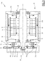
- the figure 2 represents the motor assembly 16 according to the first embodiment and which will be described later.
- the motor assembly 16 extends along a main axis A-A'.
- the motor assembly 16 comprises an electric motor 24, a casing 26 surrounding the electric motor 24 and a cooling device 28.
- the electric motor 24 is electrically powered by the electric current picked up by the pantograph 20.
- the electric motor 24 is a traction motor of the vehicle 10.
- the electric motor 24 is configured to convert the electrical energy received into mechanical energy allowing the rotational drive of the wheels 22 and thus the movement of the vehicle 10 along the track. railway 6.
- the electric motor 24 is a three-phase electric machine comprising a rotor 32, a stator 34 and an outer partition 35.
- the rotor 32 is generally cylindrical in shape and extends along the main axis A-A'.
- the rotor 32 is rotatably mounted with respect to the stator 34 around the main axis A-A'.
- Stator 34 extends around rotor 32.
- the electric motor 24 is a synchronous motor.
- the electric motor 24 is an asynchronous motor.
- the outer partition 35 extends around the stator 34 and protects the interior of the electric motor 24, in particular the stator 34 and the rotor 32.
- the casing 26 comprises a side wall 36A extending along the main axis A-A' surrounding the electric motor 24, closed at its axial ends by a front wall 36B and a rear wall 36C.
- the cross section of the side wall 36A taken perpendicular to the main axis A-A', has for example a generally rectangular shape, in particular square.
- the section perpendicular to the main axis A-A' of the side wall 36A has a generally circular or polygonal shape.
- the front wall 36B is designed to face the cooling device 28.
- the housing 26 is provided with at least one through opening 38 for the passage of an air flow for cooling the electric motor 24.
- the housing 26 comprises a plurality of openings 38.
- the openings 38 are in particular arranged on the front wall 36B and on the rear wall 36C.
- the casing 26 defines at least one cooling channel 39 of the electric motor 24 extending to the periphery of the stator 34.
- Each cooling channel 39 extends between two openings 38. Each cooling channel 39 is thus configured to be fed by the air flow via at least one of the opening(s) 38 and to emerge outside the casing 26 at the level of the other opening 38.
- the airflow is represented on the figure 2 and 3 by arrows symbolizing the direction of circulation of said air flow.
- Each cooling channel 39 is located at the periphery of the electric motor 24.
- each cooling channel 39 is in contact with the outer partition 35 of the electric motor 24.
- each cooling channel 39 extends axially along the electric motor 24, along the main axis A-A'.
- cooling channels 39 extend along the main axis AA' from the front wall 36B to the rear wall 36C.
- the circulation of the air flow in the electric motor 24 is represented by the arrows visible on the figure 2 .
- the air flow recovers the heat produced by the electric motor 24 and evacuates it from the casing 26, towards the outside of the vehicle 10.
- the cooling device 28 is configured to cool the electric motor 24.
- the cooling device 28 is configured to force a flow of air through at least one of the openings 38 in order to cool the electric motor 24.
- the cooling device 28 comprises an envelope 40, a fan 42, a device 44 for measuring the rotational speed of the fan 42 and a support plate 46 capable of accommodating an encoder wheel 64.
- the casing 40 is adapted to be placed on the front wall 36B of the casing 26 or on the side wall 36A of the casing 26.
- the casing 40 is adapted to be fixed on the casing 26, in particular on the side wall 36A of the casing 26 and/or the front wall 36B of the casing 26.
- the casing 40 is fixed by removable fixing means on the casing 26.
- the fixing means are for example screws.
- the cross section of the casing 40 taken perpendicular to the main axis A-A', is similar to that of the casing 26. Here it has an outline of generally rectangular shape, in particular square.
- it has an outline of generally circular or polygonal shape.
- the envelope 40 defines an air inlet 52 to allow the entry of the air flow inside the envelope 40.
- the air inlet 52 has an opening of circular shape for example, located on the axis A-A'.
- the air inlet 52 has a maximum transverse extent of between 20% and 70% of the maximum transverse extent of the cooling device 28.
- the casing 40 has at least one air outlet 56.
- Each air outlet 56 is intended to be fluidly connected to at least one opening 38 of the housing 26 for the air supply to this opening 38.
- the envelope 40 has a single air outlet 56 of annular shape located substantially at the periphery of the envelope 40, opposite the openings 38 of the front wall 36B of the casing 26.
- the casing 40 is hollow and delimits an air channeling duct 58 connecting the air inlet 52 to each air outlet 56.
- the cooling device 28 is configured to generate the flow of air in the air channeling duct 58 between the air inlet 52 and each air outlet 56 and thus supply the opening or openings 38 with the airflow.
- the support plate 46 is fixed on the rotor 32 of the electric motor 24.
- the support plate 46 is configured for its centering with respect to the rotor 32. It comprises for example a recess provided for the insertion of one end of the rotor 32.
- the support plate 46 is fixed by removable fixing means 59 on the rotor 32.
- the fixing means 59 are for example screws.
- the support plate 46 is made of steel, cast iron or aluminum alloy.
- the support plate 46 notably has a mass density of between 2700 kg/m 3 and 8000 kg/m 3 .
- the support plate 46 has a circular shape centered on the main axis A-A'.
- the support plate 46 has an outer diameter D in a direction orthogonal to the main axis A-A' of between 50% and 80% of the diameter of the motor casing in a direction orthogonal to the main axis A-A'.
- the support plate 46 advantageously has a thickness E along the main axis A-A' of between 5 mm and 200 mm.
- the support plate 46 has two opposite faces, including a first face 60A and a second face 60B.
- the first face 60A is opposite the electric motor 24 and the second face 60B is opposite the electric motor 24.
- the two faces 60A, 60B are advantageously parallel.
- the fan 42 is mounted inside the casing 40.
- the fan 42 is separate from the support plate 46 and fixed only on the support plate 46.
- Fan 42 is configured to force airflow from air inlet 52 to each air outlet 56.
- the fan 42 is configured to draw in a flow of air axially with respect to the main axis AA through the inlet 52 and to cause this flow of air to circulate mainly radially with respect to the main axis AA in the envelope 40.
- the envelope 40 is then configured to channel this radial air flow in the duct 58 and to exit axially through each air outlet 56.
- the fan 42 is rotatable around the main axis A-A'.
- Fan 42 includes blades 62.
- the fan 42 comprises a number of blades 62 comprised between 3 and 25.
- the fan 42 is fixed to the support plate 46 by removable fixing means 59, in particular at least one screw.
- the fan 42 is fixed on the second face 60B of the support plate 46 opposite the electric motor 24.
- Fan 42 is capable of rotating at the same speed as rotor 32 to which it is attached.
- the electric motor 24 is then said to be self-ventilated because the fan 42 is rotated by the electric motor 24 itself.
- Each blade 62 extends substantially radially relative to the main axis A-A'.
- each blade 62 extends radially over a length less than the radius of the support plate 46.
- Each blade 62 advantageously has a thickness of less than 8 mm.
- the fan 42 is composed for example solely of plastic material, of a metallic material or of a composite material.
- the metallic material is for example aluminium, titanium or steel.
- the composite material comprises for example a plastic material mixed with another material such as fiberglass or carbon fibers for example.
- the fan 42 notably has a mass density of between 500 kg/m 3 and 5000 kg/m 3 .
- the support plate 46 has a mass density strictly greater than the mass density of the blades 62.
- the device 44 for measuring the rotational speed of the fan 42 is made up of an encoder wheel 64 indirectly linked to the fan 42 and of a speed sensor 66.
- the encoder wheel 64 is a wheel having regular openings at its periphery.
- encoder wheel 64 is a toothed wheel whose teeth extend regularly over the periphery of the wheel.
- encoder wheel 64 is separate from support plate 46.
- the coding wheel 64 is fixed only on the support plate 46.
- the coding wheel 64 is fixed on the support plate 46 by removable fixing means 59, in particular here screws.
- the coding wheel 64 is in particular arranged at the periphery of the support plate 46.
- the encoder wheel 64 is then advantageously made of a ferrous material, in particular steel.
- encoder wheel 64 is integral with support plate 46.
- the encoder wheel 64 and the support plate 46 are then advantageously made of a ferrous material, in particular steel.
- the speed sensor 66 is fixed on the casing 40.
- the speed sensor 66 is arranged opposite the encoder wheel 64.
- the speed sensor 66 is suitable for measuring the speed of rotation of the encoder wheel 64.
- the speed sensor 66 is for example a magnetic sensor.
- the picture 3 represents a motorization assembly 116 according to the second embodiment and which will be described later.
- the motorization assembly 116 according to the second embodiment has a structure similar to the motorization assembly 16 according to the first embodiment and only the differences between the two embodiments will be described below.
- the motorization assembly 116 differs in that the fan 42 is fixed on the first face 60A of the support plate 46, opposite the electric motor 24.
- the air inlet 52 of the cooling device 28 is intended to be fluidly connected to at least one of the openings 38 of the housing 26 for the air supply of this opening 38.
- Each air outlet 56 is arranged on the periphery of the envelope 40.
- Fan 42 is configured to draw airflow from air inlet 52 to each air outlet 56.
- the fan 42 is configured to draw air through the air inlet 52 from the cooling channel 39 and circulate this air flow through the duct 58 to the air outlet 56 outside. of the cooling device 28.
- the air flow circulates in the cooling channel 39 of the electric motor 24 in the opposite direction with respect to the direction of circulation of the air flow in the first embodiment.
- the circulation of the air flow in the electric motor 24 is represented by the arrows visible on the picture 3 .
- the electric motor 24 is then said to be “with drawn ventilation”.
- the electric motor 24 further comprises at least one ventilation channel 68 passing through the rotor 32.
- Each ventilation channel 68 is fluidically connected to the openings 38 and to the cooling channel 39.
- the support plate 46 makes it possible to withstand most of the mechanical stresses due to the operation of the electric motor 24 and the fan 42.
- the blades 62 support less stress than in conventional fans and therefore possibly have a less solid mechanical structure without penalizing the reliability and the life of the fan 42.
- the shape of the blades 62 can thus be refined and consequently improve the aeraulic performance and reduce the noise caused by the fan 42.
Landscapes
- Engineering & Computer Science (AREA)
- Power Engineering (AREA)
- Mechanical Engineering (AREA)
- Transportation (AREA)
- Microelectronics & Electronic Packaging (AREA)
- General Engineering & Computer Science (AREA)
- Chemical & Material Sciences (AREA)
- Combustion & Propulsion (AREA)
- Motor Or Generator Cooling System (AREA)
- Electric Propulsion And Braking For Vehicles (AREA)
Abstract
- une enveloppe (40) délimitant un conduit de canalisation (58) d'air reliant une entrée d'air (52) à au moins une sortie d'air (56),
- un ventilateur (42) monté à l'intérieur de l'enveloppe (40) configuré pour forcer la circulation d'un flux d'air, et
- un dispositif de mesure (44) de la vitesse de rotation du ventilateur (42) composé d'une roue codeuse (64) liée indirectement au ventilateur (42) et d'un capteur de vitesse (66) ;
Description
- La présente invention concerne un dispositif de refroidissement d'un moteur électrique de traction d'un véhicule.
- L'invention concerne également un ensemble de motorisation comprenant un tel dispositif de refroidissement.
- L'invention concerne également un véhicule comprenant un tel ensemble de motorisation.
- Le véhicule est par exemple un véhicule ferroviaire, ou, en variante, un véhicule automobile, aérien ou maritime.
- Il est nécessaire de refroidir un moteur électrique lorsque celui-ci fonctionne afin d'éviter toute surchauffe et ainsi de garantir son bon fonctionnement.
- A cet effet, il est connu de fixer un ventilateur directement sur l'arbre du moteur. La rotation de l'arbre du moteur entraine alors la rotation du ventilateur et fait ainsi circuler un flux d'air dans le moteur. Le moteur est alors dit « autoventilé ».
- Toutefois, le ventilateur, qui est fixé sur l'arbre, est soumis à plusieurs sollicitations mécaniques dont les couples pulsatoires transmis par l'arbre et les efforts centrifuges engendrés par la rotation.
- Dans le cas où une pièce possédant une masse conséquente est fixée sur le ventilateur, ce dernier doit posséder une résistance mécanique élevée afin d'assurer un niveau satisfaisant de fiabilité. Il est alors nécessaire d'utiliser des alliages métalliques pour la fabrication du ventilateur et de dimensionner le ventilateur avec des épaisseurs importantes.
- Ainsi, le ventilateur présente une masse importante qui entraine une diminution de la performance aéraulique et une augmentation du bruit généré.
- Un des objectifs de l'invention est donc de réduire la masse du ventilateur sans toutefois pénaliser la fiabilité et la durée de vie du ventilateur.
- A cet effet, l'invention a pour objet un dispositif de refroidissement d'un moteur électrique de traction d'un véhicule, notamment d'un véhicule ferroviaire, le moteur électrique comprenant un rotor et un stator, le dispositif de refroidissement comprenant une enveloppe délimitant un conduit de canalisation d'air reliant une entrée d'air à au moins une sortie d'air, un ventilateur monté à l'intérieur de l'enveloppe et mobile en rotation autour d'un axe principal, le ventilateur comprenant des pales et étant configuré pour forcer la circulation d'un flux d'air depuis l'entrée d'air vers chaque sortie d'air, et un dispositif de mesure de la vitesse de rotation du ventilateur, le dispositif de mesure étant composé d'une roue codeuse liée indirectement au ventilateur et d'un capteur de vitesse fixé sur l'enveloppe et propre à mesurer la vitesse de rotation de la roue codeuse ; le dispositif de refroidissement comportant un plateau de support présentant deux faces opposées, le plateau de support étant propre à être fixé sur le rotor du moteur électrique ; le ventilateur étant distinct du plateau de support et fixé uniquement sur l'une des faces du plateau de support.
- Selon des modes de réalisation particuliers de l'invention, le dispositif de refroidissement comprend une ou plusieurs des caractéristiques suivantes, prises isolément ou suivant toutes les combinaisons techniquement possibles :
- la roue codeuse est distincte du plateau de support et fixée uniquement sur le plateau de support ;
- chaque pale s'étend sensiblement radialement par rapport à l'axe principal ;
- le plateau de support présente une forme circulaire centrée sur l'axe principal, chaque pale s'étendant radialement sur une longueur inférieure au rayon du plateau de support ;
- le plateau de support présente une densité massique supérieure à la densité massique des pales ;
- chaque pale présente une épaisseur inférieure à 8 mm ; et
- la roue dentée et le ventilateur sont fixés au plateau de support par des moyens de fixation amovibles.
- L'invention a également pour objet un ensemble de motorisation comprenant un moteur électrique de traction d'un véhicule, le moteur électrique comprenant un rotor et un stator ; un carter entourant le moteur électrique, le carter définissant au moins un canal de refroidissement du moteur électrique s'étendant à la périphérie du stator, et un dispositif de refroidissement tel que défini ci-dessus, le dispositif de refroidissement étant fixé sur le carter de telle sorte que le conduit de canalisation d'air soit relié fluidiquement au canal de refroidissement.
- Selon des modes de réalisation particuliers de l'invention, l'ensemble de motorisation présente également une ou plusieurs des caractéristiques suivantes, prise(s) isolément ou en combinaison :
- chaque pale est fixée sur la face du plateau de support opposée au moteur électrique ; et
- chaque pale est fixée sur la face du plateau de support en regard du moteur électrique.
- L'invention a également pour objet un véhicule, en particulier un véhicule ferroviaire, comprenant au moins un ensemble de motorisation tel que défini ci-dessus.
- L'invention et ses avantages seront mieux compris à la lecture de la description qui va suivre, donnée uniquement à titre d'exemple non limitatif, et faite en référence aux dessins annexés, sur lesquels :
- [
Fig 1 ] lafigure 1 est une représentation schématique de côté d'un véhicule ferroviaire ; et - [
Fig 2 ] lafigure 2 est une vue en coupe d'un ensemble de motorisation selon un premier mode de réalisation embarqué dans le véhicule ferroviaire de lafigure 1 ; et - [
Fig 3 ] lafigure 3 est une vue en coupe d'un ensemble de motorisation selon un deuxième mode de réalisation embarqué dans le véhicule ferroviaire de lafigure 1 . - Un système ferroviaire 2 comprenant une infrastructure ferroviaire 4 et un véhicule ferroviaire 10 est illustré sur la
figure 1 . - L'infrastructure ferroviaire 4 comprend une voie ferrée 6 et une caténaire 8.
- La caténaire 8 est un dispositif d'alimentation électrique suspendue au-dessus de la voie ferroviaire 6. La caténaire 8 comprend au moins un fil de contact électriquement conducteur. La caténaire 8 est portée par au moins un câble porteur.
- Par la suite, seul le véhicule ferroviaire 10 sera décrit mais l'homme du métier comprendra que l'invention s'applique à tout type de véhicule, par exemple à un véhicule automobile, aérien ou maritime.
- Le véhicule ferroviaire 10 est configuré pour permettre le transport de voyageurs et/ou de marchandises.
- Comme visible sur la
figure 1 , le véhicule ferroviaire 10 comporte une ou plusieurs voitures, et au moins un ensemble de motorisation 16 embarqué dans le véhicule 10. - Lorsque le véhicule 10 possède plusieurs voitures, celles-ci sont disposées à la file, les unes derrière les autres.
- Le véhicule 10 est composé par exemple d'au moins une voiture intermédiaire 12, ici deux voitures intermédiaires 12, et de deux voitures d'extrémité 14, 18. Chaque voiture d'extrémité 14, 18 est situé à une extrémité respective du véhicule 10.
- Le véhicule 10 comprend en outre au moins un pantographe 20 disposé sur l'une des voitures 12, 14, 18. Le pantographe 20 est un dispositif articulé configuré pour capter un courant électrique par frottement sur la caténaire 8.
- Chaque voiture 12, 14, 18 s'étend suivant une direction longitudinale et possède deux extrémités longitudinales.
- Le véhicule 10 comprend des bogies 17 agencés pour supporter les voitures 12,14, 18 et assurer leur guidage le long de la voie ferrée 16. Chaque bogie 17 supporte une voiture 12, 14, 18 reposant sur ce bogie 17 ou supporte deux voitures 12, 14, 18 voisines reposant par leurs extrémités longitudinales voisines sur ce bogie 17 (on parle alors de « bogie commun »).
- Chaque bogie 17 comprend des roues 22 portées par des arbres non représentés sur les figures. Les roues 22 sont configurées pour rouler sur des rails de la voie ferrée 6 et ainsi permettre le déplacement du véhicule ferroviaire 10.
- Chaque ensemble de motorisation 16 est embarqué dans une voiture 12, 14, 18. Le véhicule 10 peut comprendre un seul ensemble de motorisation 16 ou plusieurs ensembles de motorisation 16. Lorsque plusieurs ensembles de motorisation 16 sont prévus, ils peuvent être disposés dans une même voiture 12, 14, 18 ou répartis dans plusieurs voitures 12, 14, 18 du véhicule 10.
- Le véhicule 10 comprend ici un ensemble de motorisation 16 embarqué dans la voiture d'extrémité 14.
- En variante ou en option, le véhicule 10 comprend un ensemble de motorisation dans l'autre voiture d'extrémité 18.
- En variante ou en option, le véhicule 10 comprend un ensemble de motorisation 16 embarqué dans au moins une ou dans chacune des voitures intermédiaires 12.
- La
figure 2 représente l'ensemble de motorisation 16 selon le premier mode de réalisation et qui va être décrit par la suite. - L'ensemble de motorisation 16 s'étend selon un axe principal A-A'.
- L'ensemble de motorisation 16 comprend un moteur électrique 24, un carter 26 entourant le moteur électrique 24 et un dispositif de refroidissement 28.
- Le moteur électrique 24 est alimenté électriquement par le courant électrique capté par le pantographe 20.
- Le moteur électrique 24 est un moteur de traction du véhicule 10. Le moteur électrique 24 est configuré pour convertir l'énergie électrique reçue en énergie mécanique permettant l'entraînement en rotation des roues 22 et ainsi le déplacement du véhicule 10 le long de la voie ferrée 6.
- Dans l'exemple illustré sur la
figure 2 , le moteur électrique 24 est une machine électrique triphasée comportant un rotor 32, un stator 34 et une cloison extérieure 35. - Le rotor 32 est de forme générale cylindrique et s'étend le long de l'axe principal A-A'. Le rotor 32 est monté rotatif par rapport au stator 34 autour de l'axe principal A-A'.
- Le stator 34 s'étend autour du rotor 32.
- De préférence, le moteur électrique 24 est un moteur synchrone.
- En variante, le moteur électrique 24 est un moteur asynchrone.
- La cloison extérieure 35 s'étend autour du stator 34 et protège l'intérieur du moteur électrique 24, en particulier le stator 34 et le rotor 32.
- Le carter 26 comprend une paroi latérale 36A s'étendant suivant l'axe principal A-A' en entourant le moteur électrique 24, fermée à ses extrémités axiales par une paroi avant 36B et une paroi arrière 36C.
- La section transversale de la paroi latérale 36A, prise perpendiculairement à l'axe principal A-A', présente par exemple une forme générale rectangulaire, en particulier carrée.
- En variante, la section perpendiculaire à l'axe principal A-A' de la paroi latérale 36A présente une forme générale circulaire ou polygonale.
- La paroi avant 36B est prévue pour être en regard du dispositif de refroidissement 28.
- Le carter 26 est muni d'au moins une ouverture 38 traversante pour le passage d'un flux d'air pour le refroidissement du moteur électrique 24.
- Avantageusement, comme visible sur la
figure 2 , le carter 26 comprend une pluralité d'ouvertures 38. - Les ouvertures 38 sont en particulier disposées sur la paroi avant 36B et sur la paroi arrière 36C.
- Le carter 26 définit au moins un canal de refroidissement 39 du moteur électrique 24 s'étendant à la périphérie du stator 34.
- Chaque canal de refroidissement 39 s'étend entre deux ouvertures 38. Chaque canal de refroidissement 39 est ainsi configuré pour être alimenté par le flux d'air via au moins l'une des ouverture(s) 38 et pour déboucher à l'extérieur du carter 26 au niveau de l'autre ouverture 38.
- Le flux d'air est représenté sur les
figures 2 et3 par des flèches symbolisant le sens de circulation dudit flux d'air. - Chaque canal de refroidissement 39 est situé à la périphérie du moteur électrique 24.
- En particulier, chaque canal de refroidissement 39 est en contact avec la cloison extérieure 35 du moteur électrique 24.
- Avantageusement, chaque canal de refroidissement 39 s'étend axialement le long du moteur électrique 24, suivant l'axe principal A-A'.
- Ainsi, les canaux de refroidissement 39 s'étendent le long de l'axe principal A-A' depuis la paroi avant 36B jusqu'à la paroi arrière 36C.
- Lors du fonctionnement du moteur électrique 24, celui-ci produit de la chaleur qu'il est nécessaire d'évacuer afin de garantir un bon fonctionnement du moteur électrique 24.
- La circulation du flux d'air dans le moteur électrique 24 est représentée par les flèches visibles sur la
figure 2 . - Durant cette circulation, le flux d'air récupère la chaleur produite par le moteur électrique 24 et l'évacue hors du carter 26, vers l'extérieur du véhicule 10.
- Le dispositif de refroidissement 28 est configuré pour refroidir le moteur électrique 24.
- Sur la
figure 2 , le dispositif de refroidissement 28 est configuré pour forcer un flux d'air à travers au moins l'une des ouvertures 38 afin de refroidir le moteur électrique 24. - Le dispositif de refroidissement 28 comprend une enveloppe 40, un ventilateur 42, un dispositif de mesure 44 de la vitesse de rotation du ventilateur 42 et un plateau de support 46 propre à accueillir une roue codeuse 64.
- L'enveloppe 40 est propre à être disposée sur la paroi avant 36B du carter 26 ou sur la paroi latérale 36A du carter 26.
- L'enveloppe 40 est propre à être fixée sur le carter 26, en particulier sur la paroi latérale 36A du carter 26 et/ou la paroi avant 36B du carter 26.
- Selon un mode de réalisation, l'enveloppe 40 est fixée par des moyens de fixation amovibles sur le carter 26. Les moyens de fixation sont par exemple des vis.
- La section transversale de l'enveloppe 40, prise perpendiculairement à l'axe principal A-A', est semblable à celle du carter 26. Elle présente ici un contour de forme générale rectangulaire, en particulier carrée.
- En variante, elle présente un contour de forme générale circulaire ou polygonale.
- L'enveloppe 40 définit une entrée d'air 52 pour permettre l'entrée du flux d'air à l'intérieur de l'enveloppe 40.
- L'entrée d'air 52 présente une ouverture de forme circulaire par exemple, située sur l'axe A-A'.
- Avantageusement, l'entrée d'air 52 présente une étendue transversale maximale comprise entre 20 % et 70 % de l'étendue transversale maximale du dispositif de refroidissement 28.
- L'enveloppe 40 possède au moins une sortie d'air 56. Chaque sortie d'air 56 est destinée à se raccorder fluidiquement à au moins une ouverture 38 du carter 26 pour l'alimentation en air de cette ouverture 38.
- Ici, l'enveloppe 40 possède une unique sortie d'air 56 de forme annulaire située sensiblement à la périphérie de l'enveloppe 40, en regard des ouvertures 38 de la paroi avant 36B du carter 26.
- Comme visible sur la
figure 2 , l'enveloppe 40 est creuse et délimite un conduit de canalisation 58 d'air reliant l'entrée d'air 52 à chaque sortie d'air 56. - Le dispositif de refroidissement 28 est configuré pour générer le flux d'air dans le conduit de canalisation 58 d'air entre l'entrée d'air 52 et chaque sortie d'air 56 et ainsi alimenter la ou les ouverture(s) 38 avec le flux d'air.
- Le plateau de support 46 est fixé sur le rotor 32 du moteur électrique 24.
- Avantageusement, le plateau de support 46 est configuré pour son centrage par rapport au rotor 32. Il comprend par exemple un évidement prévu pour l'insertion d'une extrémité du rotor 32.
- Comme visible sur la
figure 2 , le plateau de support 46 est fixé par des moyens de fixation amovibles 59 sur le rotor 32. Les moyens de fixation 59 sont par exemple des vis. - Avantageusement, le plateau de support 46 est réalisé en acier, en fonte ou en alliage d'aluminium.
- Le plateau de support 46 présente notamment une densité massique comprise entre 2700 kg/m3 et 8000 kg/m3.
- Le plateau de support 46 présente une forme circulaire centrée sur l'axe principal A-A'.
- Le plateau de support 46 présente un diamètre extérieur D selon une direction orthogonale à l'axe principal A-A' compris entre 50 % et 80 % du diamètre de l'enveloppe du moteur selon une direction orthogonale à l'axe principal A-A'.
- Le plateau de support 46 présente avantageusement une épaisseur E selon l'axe principal A-A' comprise entre 5 mm et 200 mm.
- Comme visible sur la
figure 2 , le plateau de support 46 présente deux faces opposées, dont une première face 60A et une deuxième face 60B. La première face 60A est en regard du moteur électrique 24 et la deuxième face 60B est opposée au moteur électrique 24. - Les deux faces 60A, 60B sont avantageusement parallèles.
- Le ventilateur 42 est monté à l'intérieur de l'enveloppe 40.
- Le ventilateur 42 est distinct du plateau de support 46 et fixé uniquement sur le plateau de support 46.
- Le ventilateur 42 est configuré pour forcer la circulation d'air depuis l'entrée d'air 52 vers chaque sortie d'air 56.
- En particulier, le ventilateur 42 est configuré pour aspirer un flux d'air axialement par rapport à l'axe principal A-A par l'entrée 52 et faire circuler ce flux d'air principalement radialement par rapport à l'axe principal A-A dans l'enveloppe 40. L'enveloppe 40 est alors configurée pour canaliser ce flux d'air radial dans le conduit de canalisation 58 et le faire sortir axialement par chaque sortie d'air 56.
- A cet effet, le ventilateur 42 est mobile en rotation autour de l'axe principal A-A'.
- Le ventilateur 42 comprend des pales 62.
- En particulier, le ventilateur 42 comprend un nombre de pales 62 compris entre 3 et 25.
- Comme visible sur la
figure 2 , le ventilateur 42 est fixé sur le plateau de support 46 par des moyens de fixation amovibles 59, notamment au moins une vis. - Comme visible sur la
figure 2 , dans le premier mode de réalisation, le ventilateur 42 est fixé sur la deuxième face 60B du plateau de support 46 opposée au moteur électrique 24. - Le ventilateur 42 est propre à tourner à la même vitesse que le rotor 32 auquel il est fixé. Le moteur électrique 24 est alors dit auto-ventilé car le ventilateur 42 est mis en rotation par le moteur électrique 24 lui-même.
- Chaque pale 62 s'étend sensiblement radialement par rapport à l'axe principal A-A'.
- Selon un mode réalisation particulier, chaque pale 62 s'étend radialement sur une longueur inférieure au rayon du plateau de support 46.
- Chaque pale 62 présente avantageusement une épaisseur inférieure à 8 mm.
- Le ventilateur 42 est composé par exemple uniquement de matériau plastique, d'un matériau métallique ou d'un matériau composite.
- Le matériau métallique est par exemple de l'aluminium, du titane ou de l'acier.
- Le matériau composite comprend par exemple un matériau plastique mélangé avec un autre matériau tel que de la fibre de verre ou des fibres de carbone par exemple.
- Le ventilateur 42 présente notamment une densité massique comprise entre 500 kg/m3 et 5000 kg/m3.
- Le plateau de support 46 présente une densité massique strictement supérieure à la densité massique des pales 62.
- Le dispositif de mesure 44 de la vitesse de rotation du ventilateur 42 est composé d'une roue codeuse 64 liée indirectement au ventilateur 42 et d'un capteur de vitesse 66.
- La roue codeuse 64 est une roue présentant des ouvertures régulières à sa périphérie. Par exemple, la roue codeuse 64 est une roue dentée dont les dents s'étendent régulièrement sur la périphérie de la roue.
- Dans un mode de réalisation, la roue codeuse 64 est distincte du plateau de support 46.
- La roue codeuse 64 est fixée uniquement sur le plateau de support 46.En particulier, la roue codeuse 64 est fixée sur le plateau de support 46 par des moyens de fixation amovibles 59, notamment ici des vis.
- La roue codeuse 64 est notamment disposée à la périphérie du plateau de support 46.
- La roue codeuse 64 est alors avantageusement composé d'un matériau ferreux, notamment de l'acier.
- En variante, la roue codeuse 64 est venue de matière avec le plateau de support 46.
- La roue codeuse 64 et le plateau de support 46 sont alors avantageusement composés d'un matériau ferreux, notamment de l'acier.
- Comme visible sur la
figure 2 , le capteur de vitesse 66 est fixé sur l'enveloppe 40. - Le capteur de vitesse 66 est disposé en regard de la roue codeuse 64.
- Le capteur de vitesse 66 est propre à mesurer la vitesse de rotation de la roue codeuse 64. Le capteur de vitesse 66 est par exemple un capteur magnétique.
- La
figure 3 représente un ensemble de motorisation 116 selon le deuxième mode de réalisation et qui va être décrit par la suite. - L'ensemble de motorisation 116 selon le deuxième mode de réalisation présente une structure semblable à l'ensemble de motorisation 16 selon le premier mode de réalisation et seules les différences entre les deux modes de réalisation seront décrites par la suite.
- En particulier, l'ensemble de motorisation 116 selon le deuxième mode de réalisation diffère en ce que le ventilateur 42 est fixé sur la première face 60A du plateau de support 46, en regard du moteur électrique 24.
- Comme visible sur la
figure 3 , l'entrée d'air 52 du dispositif de refroidissement 28 est destinée à se raccorder fluidiquement à au moins l'une des ouvertures 38 du carter 26 pour l'alimentation en air de cette ouverture 38. - Chaque sortie d'air 56 est disposée sur la périphérie de l'enveloppe 40.
- Le ventilateur 42 est configuré pour tirer la circulation d'air depuis l'entrée d'air 52 vers chaque sortie d'air 56.
- En particulier, le ventilateur 42 est configuré pour aspirer par l'entrée d'air 52 depuis le canal de refroidissement 39 et faire circuler ce flux d'air à travers le conduit de canalisation 58 jusqu'à la sortie d'air 56 en dehors du dispositif de refroidissement 28.
- Ainsi, comme visible sur la
figure 3 , le flux d'air circule dans le canal de refroidissement 39 du moteur électrique 24 dans le sens inverse par rapport au sens de circulation du flux d'air dans le premier mode de réalisation. - La circulation du flux d'air dans le moteur électrique 24 est représentée par les flèches visibles sur la
figure 3 . - Le flux d'air pénètre le moteur électrique 24 par la paroi arrière 36C du carter 26, circule dans le canal de refroidissement 39 puis circule dans le dispositif de refroidissement 28 avant de s'échapper par la sortie d'air 56.
- Le moteur électrique 24 est alors dit « à ventilation tirée ».
- Avantageusement, le moteur électrique 24 comprend en outre au moins un canal de ventilation 68 traversant le rotor 32. Chaque canal de ventilation 68 est relié fluidiquement aux ouvertures 38 et au canal de refroidissement 39.
- On conçoit alors que la présente invention présente un certain nombre d'avantages.
- En effet, le plateau de support 46 permet de supporter l'essentiel des sollicitations mécaniques dues au fonctionnement du moteur électrique 24 et du ventilateur 42.
- Par conséquent, les pales 62 supportent moins de contraintes que dans les ventilateurs conventionnels et présentent donc éventuellement une structure mécanique moins solide sans pénaliser la fiabilité et la durée de vie du ventilateur 42.
- La forme des pales 62 peut ainsi être affinées et par conséquent, améliorer les performances aérauliques et réduire le bruit provoqué par le ventilateur 42.
- La fabrication de ces pales 62 est également simplifiée et moins onéreuse.
Claims (10)
- Dispositif de refroidissement (28) d'un moteur électrique (24) de traction d'un véhicule (10), notamment d'un véhicule ferroviaire, le moteur électrique (24) comprenant un rotor (32) et un stator (34), le dispositif de refroidissement (28) comprenant :- une enveloppe (40) délimitant un conduit de canalisation (58) d'air reliant une entrée d'air (52) à au moins une sortie d'air (56),- un ventilateur (42) monté à l'intérieur de l'enveloppe (40) et mobile en rotation autour d'un axe principal (A-A'), le ventilateur (42) comprenant des pales (62) et étant configuré pour forcer la circulation d'un flux d'air depuis l'entrée d'air (52) vers chaque sortie d'air (56), et- un dispositif de mesure (44) de la vitesse de rotation du ventilateur (42), le dispositif de mesure (44) étant composé d'une roue codeuse (64) liée indirectement au ventilateur (42) et d'un capteur de vitesse (66) fixé sur l'enveloppe (40) et propre à mesurer la vitesse de rotation de la roue codeuse (64),caractérisé en ce que le dispositif de refroidissement (28) comporte un plateau de support (46) présentant deux faces (60A, 60B) opposées, le plateau de support (46) étant propre à être fixé sur le rotor (32) du moteur électrique (24),
le ventilateur (42) étant distinct du plateau de support (46) et fixé uniquement sur l'une des faces (60A, 60B) du plateau de support (46). - Dispositif de refroidissement (28) selon la revendication 1, dans lequel la roue codeuse (64) est distincte du plateau de support (46) et fixée uniquement sur le plateau de support (46).
- Dispositif de refroidissement (28) selon la revendication 1 ou 2, dans lequel chaque pale (62) s'étend sensiblement radialement par rapport à l'axe principal (A-A').
- Dispositif de refroidissement (28) selon la revendication 3, dans lequel le plateau de support (46) présente une forme circulaire centrée sur l'axe principal (A-A'), chaque pale (62) s'étendant radialement sur une longueur inférieure au rayon du plateau de support (46).
- Dispositif de refroidissement (28) selon l'une quelconque des revendications précédentes, dans lequel le plateau de support (46) présente une densité massique supérieure à la densité massique des pales (62).
- Dispositif de refroidissement (28) selon l'une quelconque des revendications précédentes, dans lequel chaque pale (62) présente une épaisseur inférieure à 8 mm.
- Dispositif de refroidissement (28) selon l'une quelconque des revendications précédentes, dans lequel la roue dentée (64) et le ventilateur (42) sont fixés au plateau de support (46) par des moyens de fixation (59) amovibles.
- Ensemble de motorisation (16, 116) comprenant :- un moteur électrique (24) de traction d'un véhicule (10), le moteur électrique (24) comprenant un rotor (32) et un stator (34) ;- un carter (26) entourant le moteur électrique (24), le carter (26) définissant au moins un canal de refroidissement (39) du moteur électrique (24) s'étendant à la périphérie du stator (34), et- un dispositif de refroidissement (28) selon l'une quelconque des revendications précédentes, le dispositif de refroidissement (28) étant fixé sur le carter (26) de telle sorte que le conduit de canalisation (58) d'air soit relié fluidiquement au canal de refroidissement (39).
- Ensemble de motorisation (16) selon la revendication 8, dans lequel chaque pale (62) est fixée sur la face du plateau de support (46) opposée au moteur électrique (24) ou sur la face du plateau de support (46) en regard du moteur électrique (24).
- Véhicule (10), notamment véhicule ferroviaire, comprenant au moins un ensemble de motorisation (16, 116) selon l'une quelconque des revendications 8 ou 9.
Applications Claiming Priority (1)
| Application Number | Priority Date | Filing Date | Title |
|---|---|---|---|
| FR2100953A FR3119343B1 (fr) | 2021-02-01 | 2021-02-01 | Dispositif de refroidissement d’un moteur électrique, ensemble de motorisation et véhicule associés |
Publications (2)
| Publication Number | Publication Date |
|---|---|
| EP4035916A1 true EP4035916A1 (fr) | 2022-08-03 |
| EP4035916B1 EP4035916B1 (fr) | 2023-05-10 |
Family
ID=76523001
Family Applications (1)
| Application Number | Title | Priority Date | Filing Date |
|---|---|---|---|
| EP22154340.8A Active EP4035916B1 (fr) | 2021-02-01 | 2022-01-31 | Dispositif de refroidissement d'un moteur électrique, ensemble de motorisation et véhicule associés |
Country Status (6)
| Country | Link |
|---|---|
| EP (1) | EP4035916B1 (fr) |
| JP (1) | JP2022117969A (fr) |
| CN (1) | CN114844281A (fr) |
| ES (1) | ES2951150T3 (fr) |
| FR (1) | FR3119343B1 (fr) |
| HU (1) | HUE062364T2 (fr) |
Cited By (2)
| Publication number | Priority date | Publication date | Assignee | Title |
|---|---|---|---|---|
| CN116669378A (zh) * | 2023-05-18 | 2023-08-29 | 中国航发贵阳发动机设计研究所 | 一种航空发动机动应力测量试验用引电器冷却装置 |
| EP4697570A1 (fr) * | 2024-08-14 | 2026-02-18 | ALSTOM Holdings | Dispositif de refroidissement pour moteur de traction électrique de véhicule, ensemble de motorisation et véhicule associés et procédé de fabrication associé |
Families Citing this family (1)
| Publication number | Priority date | Publication date | Assignee | Title |
|---|---|---|---|---|
| CN114487466B (zh) * | 2021-12-22 | 2023-11-24 | 浙江英洛华磁业有限公司 | 一种转子总成转速测试装置 |
Citations (3)
| Publication number | Priority date | Publication date | Assignee | Title |
|---|---|---|---|---|
| EP1100184A1 (fr) * | 1999-11-09 | 2001-05-16 | Alstom | Dispositif de ventilation et moteur électrique de traction ferroviaire équipé d'un tel dispositif |
| JP2016021815A (ja) * | 2014-07-14 | 2016-02-04 | 株式会社東芝 | 車両用回転電機の冷却構造 |
| CN110474470A (zh) * | 2019-07-10 | 2019-11-19 | 中车永济电机有限公司 | 低损耗、低噪音的100%低地板车用全封闭自通风牵引电机 |
Family Cites Families (4)
| Publication number | Priority date | Publication date | Assignee | Title |
|---|---|---|---|---|
| JP2002359949A (ja) * | 2001-05-31 | 2002-12-13 | Toshiba Transport Eng Inc | 鉄道車両用駆動電動機 |
| JP2011125201A (ja) * | 2009-12-14 | 2011-06-23 | Hitachi Industrial Equipment Systems Co Ltd | 磁気式エンコーダを搭載した電動機 |
| JP2014128094A (ja) * | 2012-12-26 | 2014-07-07 | Keihin Corp | 電動機 |
| JP6352701B2 (ja) * | 2014-07-01 | 2018-07-04 | 株式会社東芝 | 全閉型電動機 |
-
2021
- 2021-02-01 FR FR2100953A patent/FR3119343B1/fr active Active
-
2022
- 2022-01-27 CN CN202210102265.7A patent/CN114844281A/zh active Pending
- 2022-01-31 JP JP2022012883A patent/JP2022117969A/ja active Pending
- 2022-01-31 ES ES22154340T patent/ES2951150T3/es active Active
- 2022-01-31 EP EP22154340.8A patent/EP4035916B1/fr active Active
-
2023
- 2023-05-10 HU HUE22154340A patent/HUE062364T2/hu unknown
Patent Citations (3)
| Publication number | Priority date | Publication date | Assignee | Title |
|---|---|---|---|---|
| EP1100184A1 (fr) * | 1999-11-09 | 2001-05-16 | Alstom | Dispositif de ventilation et moteur électrique de traction ferroviaire équipé d'un tel dispositif |
| JP2016021815A (ja) * | 2014-07-14 | 2016-02-04 | 株式会社東芝 | 車両用回転電機の冷却構造 |
| CN110474470A (zh) * | 2019-07-10 | 2019-11-19 | 中车永济电机有限公司 | 低损耗、低噪音的100%低地板车用全封闭自通风牵引电机 |
Cited By (2)
| Publication number | Priority date | Publication date | Assignee | Title |
|---|---|---|---|---|
| CN116669378A (zh) * | 2023-05-18 | 2023-08-29 | 中国航发贵阳发动机设计研究所 | 一种航空发动机动应力测量试验用引电器冷却装置 |
| EP4697570A1 (fr) * | 2024-08-14 | 2026-02-18 | ALSTOM Holdings | Dispositif de refroidissement pour moteur de traction électrique de véhicule, ensemble de motorisation et véhicule associés et procédé de fabrication associé |
Also Published As
| Publication number | Publication date |
|---|---|
| JP2022117969A (ja) | 2022-08-12 |
| FR3119343B1 (fr) | 2023-01-27 |
| CN114844281A (zh) | 2022-08-02 |
| HUE062364T2 (hu) | 2023-10-28 |
| EP4035916B1 (fr) | 2023-05-10 |
| ES2951150T3 (es) | 2023-10-18 |
| FR3119343A1 (fr) | 2022-08-05 |
Similar Documents
| Publication | Publication Date | Title |
|---|---|---|
| EP4035916B1 (fr) | Dispositif de refroidissement d'un moteur électrique, ensemble de motorisation et véhicule associés | |
| EP1100184B1 (fr) | Dispositif de ventilation et moteur électrique de traction ferroviaire équipé d'un tel dispositif | |
| EP2311172B1 (fr) | Machine electrique tournante | |
| EP3645903B1 (fr) | Ensemble d'entrainement d'une machine electrique tournante pour un vehicule automobile | |
| EP3819148B1 (fr) | Dispositif de refroidissement d'un moteur électrique de traction d'un véhicule, ensemble de motorisation, véhicule et procédé de remplacement associés | |
| FR2933544A1 (fr) | Machine comprenant un dispositif de continuite electrique entre sa structure porteuse et son arbre | |
| FR3091916A1 (fr) | Système d’entraînement mécanique et motocompresseur associé | |
| EP1505030B1 (fr) | Machine électrique, notamment pour ascenseur | |
| FR3056356A1 (fr) | Manchon et arbre de machine electrique | |
| EP3926793A1 (fr) | Equipement électrique à tolérance thermique améliorée, et véhicule associé | |
| FR2602925A1 (fr) | Dispositif interne de ventilation pour une machine electrique tournante telle qu'un alternateur | |
| EP0343313B1 (fr) | Moteur électrique de puissance élevée et à vitesse de rotation élevée | |
| EP0244307B1 (fr) | Perfectionnements apportés aux rotors induits des ralentisseurs électromagnétiques | |
| EP4170873B1 (fr) | Machine électrique tournante et véhicule associé | |
| FR2922060A1 (fr) | Machine electrique tournante comportant deux stators | |
| EP3795838A1 (fr) | Ventilateur de rotor amélioré | |
| EP4203270B1 (fr) | Moteur électrique et véhicule de transport en commun comportant un tel moteur | |
| EP4080733A1 (fr) | Machine électrique à canal de refroidissement et stator isolé | |
| EP4016818B1 (fr) | Rotor de machine electrique tournante et machine electrique tournante equipee d'un tel rotor | |
| FR2864367A1 (fr) | Dispositif de ventilation pour machine electrique tournante autour d'un arbre, a ventilateur independant de l'arbre | |
| FR3163226A1 (fr) | Ensemble de rotor pour une machine électrique à flux axial, notamment de véhicule automobile, et machine électrique à flux axial le comprenant | |
| EP4213345A1 (fr) | Equipement électrique à tolérance thermique améliorée, et véhicule associé | |
| FR3163228A1 (fr) | Ensemble de rotor pour une machine électrique à flux axial, notamment de véhicule automobile, et machine électrique à flux axial le comprenant | |
| FR2893459A1 (fr) | Machine electrique tournante. | |
| EP4020772A1 (fr) | Moteur électrique et véhicule comportant un tel moteur |
Legal Events
| Date | Code | Title | Description |
|---|---|---|---|
| PUAI | Public reference made under article 153(3) epc to a published international application that has entered the european phase |
Free format text: ORIGINAL CODE: 0009012 |
|
| STAA | Information on the status of an ep patent application or granted ep patent |
Free format text: STATUS: THE APPLICATION HAS BEEN PUBLISHED |
|
| STAA | Information on the status of an ep patent application or granted ep patent |
Free format text: STATUS: REQUEST FOR EXAMINATION WAS MADE |
|
| AK | Designated contracting states |
Kind code of ref document: A1 Designated state(s): AL AT BE BG CH CY CZ DE DK EE ES FI FR GB GR HR HU IE IS IT LI LT LU LV MC MK MT NL NO PL PT RO RS SE SI SK SM TR |
|
| 17P | Request for examination filed |
Effective date: 20220715 |
|
| RBV | Designated contracting states (corrected) |
Designated state(s): AL AT BE BG CH CY CZ DE DK EE ES FI FR GB GR HR HU IE IS IT LI LT LU LV MC MK MT NL NO PL PT RO RS SE SI SK SM TR |
|
| GRAP | Despatch of communication of intention to grant a patent |
Free format text: ORIGINAL CODE: EPIDOSNIGR1 |
|
| STAA | Information on the status of an ep patent application or granted ep patent |
Free format text: STATUS: GRANT OF PATENT IS INTENDED |
|
| RIC1 | Information provided on ipc code assigned before grant |
Ipc: H02K 11/22 20160101ALI20221117BHEP Ipc: H02K 5/20 20060101ALI20221117BHEP Ipc: H02K 9/06 20060101ALI20221117BHEP Ipc: B60K 11/08 20060101ALI20221117BHEP Ipc: B60K 11/06 20060101ALI20221117BHEP Ipc: B60K 11/00 20060101ALI20221117BHEP Ipc: F04D 29/28 20060101ALI20221117BHEP Ipc: F04D 27/00 20060101ALI20221117BHEP Ipc: F04D 25/08 20060101ALI20221117BHEP Ipc: B60K 1/00 20060101AFI20221117BHEP |
|
| INTG | Intention to grant announced |
Effective date: 20221207 |
|
| GRAS | Grant fee paid |
Free format text: ORIGINAL CODE: EPIDOSNIGR3 |
|
| GRAA | (expected) grant |
Free format text: ORIGINAL CODE: 0009210 |
|
| STAA | Information on the status of an ep patent application or granted ep patent |
Free format text: STATUS: THE PATENT HAS BEEN GRANTED |
|
| AK | Designated contracting states |
Kind code of ref document: B1 Designated state(s): AL AT BE BG CH CY CZ DE DK EE ES FI FR GB GR HR HU IE IS IT LI LT LU LV MC MK MT NL NO PL PT RO RS SE SI SK SM TR |
|
| REG | Reference to a national code |
Ref country code: GB Ref legal event code: FG4D Free format text: NOT ENGLISH |
|
| REG | Reference to a national code |
Ref country code: AT Ref legal event code: REF Ref document number: 1566363 Country of ref document: AT Kind code of ref document: T Effective date: 20230515 Ref country code: CH Ref legal event code: EP |
|
| REG | Reference to a national code |
Ref country code: DE Ref legal event code: R096 Ref document number: 602022000068 Country of ref document: DE |
|
| REG | Reference to a national code |
Ref country code: IE Ref legal event code: FG4D Free format text: LANGUAGE OF EP DOCUMENT: FRENCH |
|
| REG | Reference to a national code |
Ref country code: SE Ref legal event code: TRGR |
|
| REG | Reference to a national code |
Ref country code: LT Ref legal event code: MG9D |
|
| REG | Reference to a national code |
Ref country code: NL Ref legal event code: MP Effective date: 20230510 |
|
| P01 | Opt-out of the competence of the unified patent court (upc) registered |
Effective date: 20230823 |
|
| REG | Reference to a national code |
Ref country code: ES Ref legal event code: FG2A Ref document number: 2951150 Country of ref document: ES Kind code of ref document: T3 Effective date: 20231018 |
|
| REG | Reference to a national code |
Ref country code: HU Ref legal event code: AG4A Ref document number: E062364 Country of ref document: HU |
|
| PG25 | Lapsed in a contracting state [announced via postgrant information from national office to epo] |
Ref country code: PT Free format text: LAPSE BECAUSE OF FAILURE TO SUBMIT A TRANSLATION OF THE DESCRIPTION OR TO PAY THE FEE WITHIN THE PRESCRIBED TIME-LIMIT Effective date: 20230911 Ref country code: NO Free format text: LAPSE BECAUSE OF FAILURE TO SUBMIT A TRANSLATION OF THE DESCRIPTION OR TO PAY THE FEE WITHIN THE PRESCRIBED TIME-LIMIT Effective date: 20230810 Ref country code: NL Free format text: LAPSE BECAUSE OF FAILURE TO SUBMIT A TRANSLATION OF THE DESCRIPTION OR TO PAY THE FEE WITHIN THE PRESCRIBED TIME-LIMIT Effective date: 20230510 |
|
| PG25 | Lapsed in a contracting state [announced via postgrant information from national office to epo] |
Ref country code: RS Free format text: LAPSE BECAUSE OF FAILURE TO SUBMIT A TRANSLATION OF THE DESCRIPTION OR TO PAY THE FEE WITHIN THE PRESCRIBED TIME-LIMIT Effective date: 20230510 Ref country code: PL Free format text: LAPSE BECAUSE OF FAILURE TO SUBMIT A TRANSLATION OF THE DESCRIPTION OR TO PAY THE FEE WITHIN THE PRESCRIBED TIME-LIMIT Effective date: 20230510 Ref country code: LV Free format text: LAPSE BECAUSE OF FAILURE TO SUBMIT A TRANSLATION OF THE DESCRIPTION OR TO PAY THE FEE WITHIN THE PRESCRIBED TIME-LIMIT Effective date: 20230510 Ref country code: LT Free format text: LAPSE BECAUSE OF FAILURE TO SUBMIT A TRANSLATION OF THE DESCRIPTION OR TO PAY THE FEE WITHIN THE PRESCRIBED TIME-LIMIT Effective date: 20230510 Ref country code: IS Free format text: LAPSE BECAUSE OF FAILURE TO SUBMIT A TRANSLATION OF THE DESCRIPTION OR TO PAY THE FEE WITHIN THE PRESCRIBED TIME-LIMIT Effective date: 20230910 Ref country code: HR Free format text: LAPSE BECAUSE OF FAILURE TO SUBMIT A TRANSLATION OF THE DESCRIPTION OR TO PAY THE FEE WITHIN THE PRESCRIBED TIME-LIMIT Effective date: 20230510 Ref country code: GR Free format text: LAPSE BECAUSE OF FAILURE TO SUBMIT A TRANSLATION OF THE DESCRIPTION OR TO PAY THE FEE WITHIN THE PRESCRIBED TIME-LIMIT Effective date: 20230811 |
|
| PG25 | Lapsed in a contracting state [announced via postgrant information from national office to epo] |
Ref country code: FI Free format text: LAPSE BECAUSE OF FAILURE TO SUBMIT A TRANSLATION OF THE DESCRIPTION OR TO PAY THE FEE WITHIN THE PRESCRIBED TIME-LIMIT Effective date: 20230510 |
|
| PG25 | Lapsed in a contracting state [announced via postgrant information from national office to epo] |
Ref country code: SK Free format text: LAPSE BECAUSE OF FAILURE TO SUBMIT A TRANSLATION OF THE DESCRIPTION OR TO PAY THE FEE WITHIN THE PRESCRIBED TIME-LIMIT Effective date: 20230510 |
|
| PG25 | Lapsed in a contracting state [announced via postgrant information from national office to epo] |
Ref country code: SM Free format text: LAPSE BECAUSE OF FAILURE TO SUBMIT A TRANSLATION OF THE DESCRIPTION OR TO PAY THE FEE WITHIN THE PRESCRIBED TIME-LIMIT Effective date: 20230510 Ref country code: SK Free format text: LAPSE BECAUSE OF FAILURE TO SUBMIT A TRANSLATION OF THE DESCRIPTION OR TO PAY THE FEE WITHIN THE PRESCRIBED TIME-LIMIT Effective date: 20230510 Ref country code: RO Free format text: LAPSE BECAUSE OF FAILURE TO SUBMIT A TRANSLATION OF THE DESCRIPTION OR TO PAY THE FEE WITHIN THE PRESCRIBED TIME-LIMIT Effective date: 20230510 Ref country code: EE Free format text: LAPSE BECAUSE OF FAILURE TO SUBMIT A TRANSLATION OF THE DESCRIPTION OR TO PAY THE FEE WITHIN THE PRESCRIBED TIME-LIMIT Effective date: 20230510 Ref country code: DK Free format text: LAPSE BECAUSE OF FAILURE TO SUBMIT A TRANSLATION OF THE DESCRIPTION OR TO PAY THE FEE WITHIN THE PRESCRIBED TIME-LIMIT Effective date: 20230510 Ref country code: CZ Free format text: LAPSE BECAUSE OF FAILURE TO SUBMIT A TRANSLATION OF THE DESCRIPTION OR TO PAY THE FEE WITHIN THE PRESCRIBED TIME-LIMIT Effective date: 20230510 |
|
| REG | Reference to a national code |
Ref country code: DE Ref legal event code: R097 Ref document number: 602022000068 Country of ref document: DE |
|
| PLBE | No opposition filed within time limit |
Free format text: ORIGINAL CODE: 0009261 |
|
| REG | Reference to a national code |
Ref country code: AT Ref legal event code: UEP Ref document number: 1566363 Country of ref document: AT Kind code of ref document: T Effective date: 20230510 |
|
| STAA | Information on the status of an ep patent application or granted ep patent |
Free format text: STATUS: NO OPPOSITION FILED WITHIN TIME LIMIT |
|
| 26N | No opposition filed |
Effective date: 20240213 |
|
| PG25 | Lapsed in a contracting state [announced via postgrant information from national office to epo] |
Ref country code: SI Free format text: LAPSE BECAUSE OF FAILURE TO SUBMIT A TRANSLATION OF THE DESCRIPTION OR TO PAY THE FEE WITHIN THE PRESCRIBED TIME-LIMIT Effective date: 20230510 |
|
| PG25 | Lapsed in a contracting state [announced via postgrant information from national office to epo] |
Ref country code: SI Free format text: LAPSE BECAUSE OF FAILURE TO SUBMIT A TRANSLATION OF THE DESCRIPTION OR TO PAY THE FEE WITHIN THE PRESCRIBED TIME-LIMIT Effective date: 20230510 Ref country code: IT Free format text: LAPSE BECAUSE OF FAILURE TO SUBMIT A TRANSLATION OF THE DESCRIPTION OR TO PAY THE FEE WITHIN THE PRESCRIBED TIME-LIMIT Effective date: 20230510 |
|
| PG25 | Lapsed in a contracting state [announced via postgrant information from national office to epo] |
Ref country code: MC Free format text: LAPSE BECAUSE OF FAILURE TO SUBMIT A TRANSLATION OF THE DESCRIPTION OR TO PAY THE FEE WITHIN THE PRESCRIBED TIME-LIMIT Effective date: 20230510 |
|
| PG25 | Lapsed in a contracting state [announced via postgrant information from national office to epo] |
Ref country code: MC Free format text: LAPSE BECAUSE OF FAILURE TO SUBMIT A TRANSLATION OF THE DESCRIPTION OR TO PAY THE FEE WITHIN THE PRESCRIBED TIME-LIMIT Effective date: 20230510 |
|
| PG25 | Lapsed in a contracting state [announced via postgrant information from national office to epo] |
Ref country code: LU Free format text: LAPSE BECAUSE OF NON-PAYMENT OF DUE FEES Effective date: 20240131 |
|
| PG25 | Lapsed in a contracting state [announced via postgrant information from national office to epo] |
Ref country code: LU Free format text: LAPSE BECAUSE OF NON-PAYMENT OF DUE FEES Effective date: 20240131 |
|
| PG25 | Lapsed in a contracting state [announced via postgrant information from national office to epo] |
Ref country code: BE Free format text: LAPSE BECAUSE OF NON-PAYMENT OF DUE FEES Effective date: 20240131 |
|
| PG25 | Lapsed in a contracting state [announced via postgrant information from national office to epo] |
Ref country code: BE Free format text: LAPSE BECAUSE OF NON-PAYMENT OF DUE FEES Effective date: 20240131 |
|
| REG | Reference to a national code |
Ref country code: BE Ref legal event code: MM Effective date: 20240131 |
|
| PG25 | Lapsed in a contracting state [announced via postgrant information from national office to epo] |
Ref country code: BG Free format text: LAPSE BECAUSE OF FAILURE TO SUBMIT A TRANSLATION OF THE DESCRIPTION OR TO PAY THE FEE WITHIN THE PRESCRIBED TIME-LIMIT Effective date: 20230510 |
|
| PG25 | Lapsed in a contracting state [announced via postgrant information from national office to epo] |
Ref country code: BG Free format text: LAPSE BECAUSE OF FAILURE TO SUBMIT A TRANSLATION OF THE DESCRIPTION OR TO PAY THE FEE WITHIN THE PRESCRIBED TIME-LIMIT Effective date: 20230510 |
|
| PG25 | Lapsed in a contracting state [announced via postgrant information from national office to epo] |
Ref country code: IE Free format text: LAPSE BECAUSE OF NON-PAYMENT OF DUE FEES Effective date: 20240131 |
|
| PG25 | Lapsed in a contracting state [announced via postgrant information from national office to epo] |
Ref country code: IE Free format text: LAPSE BECAUSE OF NON-PAYMENT OF DUE FEES Effective date: 20240131 |
|
| PGFP | Annual fee paid to national office [announced via postgrant information from national office to epo] |
Ref country code: AT Payment date: 20250417 Year of fee payment: 4 |
|
| PG25 | Lapsed in a contracting state [announced via postgrant information from national office to epo] |
Ref country code: CY Free format text: LAPSE BECAUSE OF FAILURE TO SUBMIT A TRANSLATION OF THE DESCRIPTION OR TO PAY THE FEE WITHIN THE PRESCRIBED TIME-LIMIT; INVALID AB INITIO Effective date: 20220131 |
|
| REG | Reference to a national code |
Ref country code: CH Ref legal event code: PL |
|
| PG25 | Lapsed in a contracting state [announced via postgrant information from national office to epo] |
Ref country code: CH Free format text: LAPSE BECAUSE OF NON-PAYMENT OF DUE FEES Effective date: 20250131 |
|
| PG25 | Lapsed in a contracting state [announced via postgrant information from national office to epo] |
Ref country code: TR Free format text: LAPSE BECAUSE OF FAILURE TO SUBMIT A TRANSLATION OF THE DESCRIPTION OR TO PAY THE FEE WITHIN THE PRESCRIBED TIME-LIMIT Effective date: 20230510 |
|
| PGFP | Annual fee paid to national office [announced via postgrant information from national office to epo] |
Ref country code: HU Payment date: 20260123 Year of fee payment: 5 |
|
| PGFP | Annual fee paid to national office [announced via postgrant information from national office to epo] |
Ref country code: SE Payment date: 20260121 Year of fee payment: 5 |
|
| PGFP | Annual fee paid to national office [announced via postgrant information from national office to epo] |
Ref country code: ES Payment date: 20260227 Year of fee payment: 5 |
|
| PGFP | Annual fee paid to national office [announced via postgrant information from national office to epo] |
Ref country code: DE Payment date: 20260121 Year of fee payment: 5 |
|
| PGFP | Annual fee paid to national office [announced via postgrant information from national office to epo] |
Ref country code: FR Payment date: 20260123 Year of fee payment: 5 |