EP4035886A1 - Interior material for vehicle and method for manufacturing same - Google Patents
Interior material for vehicle and method for manufacturing same Download PDFInfo
- Publication number
- EP4035886A1 EP4035886A1 EP20868509.9A EP20868509A EP4035886A1 EP 4035886 A1 EP4035886 A1 EP 4035886A1 EP 20868509 A EP20868509 A EP 20868509A EP 4035886 A1 EP4035886 A1 EP 4035886A1
- Authority
- EP
- European Patent Office
- Prior art keywords
- material layer
- layer
- vehicle
- decorative part
- surface material
- Prior art date
- Legal status (The legal status is an assumption and is not a legal conclusion. Google has not performed a legal analysis and makes no representation as to the accuracy of the status listed.)
- Pending
Links
Images


Classifications
-
- B—PERFORMING OPERATIONS; TRANSPORTING
- B44—DECORATIVE ARTS
- B44C—PRODUCING DECORATIVE EFFECTS; MOSAICS; TARSIA WORK; PAPERHANGING
- B44C3/00—Processes, not specifically provided for elsewhere, for producing ornamental structures
- B44C3/005—Removing selectively parts of at least the upper layer of a multi-layer article
-
- B—PERFORMING OPERATIONS; TRANSPORTING
- B29—WORKING OF PLASTICS; WORKING OF SUBSTANCES IN A PLASTIC STATE IN GENERAL
- B29C—SHAPING OR JOINING OF PLASTICS; SHAPING OF MATERIAL IN A PLASTIC STATE, NOT OTHERWISE PROVIDED FOR; AFTER-TREATMENT OF THE SHAPED PRODUCTS, e.g. REPAIRING
- B29C45/00—Injection moulding, i.e. forcing the required volume of moulding material through a nozzle into a closed mould; Apparatus therefor
- B29C45/14—Injection moulding, i.e. forcing the required volume of moulding material through a nozzle into a closed mould; Apparatus therefor incorporating preformed parts or layers, e.g. injection moulding around inserts or for coating articles
- B29C45/14778—Injection moulding, i.e. forcing the required volume of moulding material through a nozzle into a closed mould; Apparatus therefor incorporating preformed parts or layers, e.g. injection moulding around inserts or for coating articles the article consisting of a material with particular properties, e.g. porous, brittle
- B29C45/14811—Multilayered articles
-
- B—PERFORMING OPERATIONS; TRANSPORTING
- B32—LAYERED PRODUCTS
- B32B—LAYERED PRODUCTS, i.e. PRODUCTS BUILT-UP OF STRATA OF FLAT OR NON-FLAT, e.g. CELLULAR OR HONEYCOMB, FORM
- B32B21/00—Layered products comprising a layer of wood, e.g. wood board, veneer, wood particle board
- B32B21/10—Next to a fibrous or filamentary layer
-
- B—PERFORMING OPERATIONS; TRANSPORTING
- B32—LAYERED PRODUCTS
- B32B—LAYERED PRODUCTS, i.e. PRODUCTS BUILT-UP OF STRATA OF FLAT OR NON-FLAT, e.g. CELLULAR OR HONEYCOMB, FORM
- B32B21/00—Layered products comprising a layer of wood, e.g. wood board, veneer, wood particle board
- B32B21/14—Layered products comprising a layer of wood, e.g. wood board, veneer, wood particle board comprising wood board or veneer
-
- B—PERFORMING OPERATIONS; TRANSPORTING
- B32—LAYERED PRODUCTS
- B32B—LAYERED PRODUCTS, i.e. PRODUCTS BUILT-UP OF STRATA OF FLAT OR NON-FLAT, e.g. CELLULAR OR HONEYCOMB, FORM
- B32B3/00—Layered products comprising a layer with external or internal discontinuities or unevennesses, or a layer of non-planar form; Layered products having particular features of form
- B32B3/02—Layered products comprising a layer with external or internal discontinuities or unevennesses, or a layer of non-planar form; Layered products having particular features of form characterised by features of form at particular places, e.g. in edge regions
- B32B3/08—Layered products comprising a layer with external or internal discontinuities or unevennesses, or a layer of non-planar form; Layered products having particular features of form characterised by features of form at particular places, e.g. in edge regions characterised by added members at particular parts
-
- B—PERFORMING OPERATIONS; TRANSPORTING
- B32—LAYERED PRODUCTS
- B32B—LAYERED PRODUCTS, i.e. PRODUCTS BUILT-UP OF STRATA OF FLAT OR NON-FLAT, e.g. CELLULAR OR HONEYCOMB, FORM
- B32B3/00—Layered products comprising a layer with external or internal discontinuities or unevennesses, or a layer of non-planar form; Layered products having particular features of form
- B32B3/26—Layered products comprising a layer with external or internal discontinuities or unevennesses, or a layer of non-planar form; Layered products having particular features of form characterised by a particular shape of the outline of the cross-section of a continuous layer; characterised by a layer with cavities or internal voids ; characterised by an apertured layer
- B32B3/266—Layered products comprising a layer with external or internal discontinuities or unevennesses, or a layer of non-planar form; Layered products having particular features of form characterised by a particular shape of the outline of the cross-section of a continuous layer; characterised by a layer with cavities or internal voids ; characterised by an apertured layer characterised by an apertured layer, the apertures going through the whole thickness of the layer, e.g. expanded metal, perforated layer, slit layer regular cells B32B3/12
-
- B—PERFORMING OPERATIONS; TRANSPORTING
- B32—LAYERED PRODUCTS
- B32B—LAYERED PRODUCTS, i.e. PRODUCTS BUILT-UP OF STRATA OF FLAT OR NON-FLAT, e.g. CELLULAR OR HONEYCOMB, FORM
- B32B3/00—Layered products comprising a layer with external or internal discontinuities or unevennesses, or a layer of non-planar form; Layered products having particular features of form
- B32B3/26—Layered products comprising a layer with external or internal discontinuities or unevennesses, or a layer of non-planar form; Layered products having particular features of form characterised by a particular shape of the outline of the cross-section of a continuous layer; characterised by a layer with cavities or internal voids ; characterised by an apertured layer
- B32B3/30—Layered products comprising a layer with external or internal discontinuities or unevennesses, or a layer of non-planar form; Layered products having particular features of form characterised by a particular shape of the outline of the cross-section of a continuous layer; characterised by a layer with cavities or internal voids ; characterised by an apertured layer characterised by a layer formed with recesses or projections, e.g. hollows, grooves, protuberances, ribs
-
- B—PERFORMING OPERATIONS; TRANSPORTING
- B32—LAYERED PRODUCTS
- B32B—LAYERED PRODUCTS, i.e. PRODUCTS BUILT-UP OF STRATA OF FLAT OR NON-FLAT, e.g. CELLULAR OR HONEYCOMB, FORM
- B32B5/00—Layered products characterised by the non- homogeneity or physical structure, i.e. comprising a fibrous, filamentary, particulate or foam layer; Layered products characterised by having a layer differing constitutionally or physically in different parts
- B32B5/02—Layered products characterised by the non- homogeneity or physical structure, i.e. comprising a fibrous, filamentary, particulate or foam layer; Layered products characterised by having a layer differing constitutionally or physically in different parts characterised by structural features of a fibrous or filamentary layer
- B32B5/022—Non-woven fabric
-
- B—PERFORMING OPERATIONS; TRANSPORTING
- B32—LAYERED PRODUCTS
- B32B—LAYERED PRODUCTS, i.e. PRODUCTS BUILT-UP OF STRATA OF FLAT OR NON-FLAT, e.g. CELLULAR OR HONEYCOMB, FORM
- B32B5/00—Layered products characterised by the non- homogeneity or physical structure, i.e. comprising a fibrous, filamentary, particulate or foam layer; Layered products characterised by having a layer differing constitutionally or physically in different parts
- B32B5/22—Layered products characterised by the non- homogeneity or physical structure, i.e. comprising a fibrous, filamentary, particulate or foam layer; Layered products characterised by having a layer differing constitutionally or physically in different parts characterised by the presence of two or more layers which are next to each other and are fibrous, filamentary, formed of particles or foamed
- B32B5/24—Layered products characterised by the non- homogeneity or physical structure, i.e. comprising a fibrous, filamentary, particulate or foam layer; Layered products characterised by having a layer differing constitutionally or physically in different parts characterised by the presence of two or more layers which are next to each other and are fibrous, filamentary, formed of particles or foamed one layer being a fibrous or filamentary layer
- B32B5/26—Layered products characterised by the non- homogeneity or physical structure, i.e. comprising a fibrous, filamentary, particulate or foam layer; Layered products characterised by having a layer differing constitutionally or physically in different parts characterised by the presence of two or more layers which are next to each other and are fibrous, filamentary, formed of particles or foamed one layer being a fibrous or filamentary layer another layer next to it also being fibrous or filamentary
- B32B5/265—Layered products characterised by the non- homogeneity or physical structure, i.e. comprising a fibrous, filamentary, particulate or foam layer; Layered products characterised by having a layer differing constitutionally or physically in different parts characterised by the presence of two or more layers which are next to each other and are fibrous, filamentary, formed of particles or foamed one layer being a fibrous or filamentary layer another layer next to it also being fibrous or filamentary characterised by one fibrous or filamentary layer being a non-woven fabric layer
- B32B5/266—Layered products characterised by the non- homogeneity or physical structure, i.e. comprising a fibrous, filamentary, particulate or foam layer; Layered products characterised by having a layer differing constitutionally or physically in different parts characterised by the presence of two or more layers which are next to each other and are fibrous, filamentary, formed of particles or foamed one layer being a fibrous or filamentary layer another layer next to it also being fibrous or filamentary characterised by one fibrous or filamentary layer being a non-woven fabric layer next to one or more non-woven fabric layers
-
- B—PERFORMING OPERATIONS; TRANSPORTING
- B32—LAYERED PRODUCTS
- B32B—LAYERED PRODUCTS, i.e. PRODUCTS BUILT-UP OF STRATA OF FLAT OR NON-FLAT, e.g. CELLULAR OR HONEYCOMB, FORM
- B32B9/00—Layered products comprising a layer of a particular substance not covered by groups B32B11/00 - B32B29/00
- B32B9/005—Layered products comprising a layer of a particular substance not covered by groups B32B11/00 - B32B29/00 comprising one layer of ceramic material, e.g. porcelain, ceramic tile
- B32B9/007—Layered products comprising a layer of a particular substance not covered by groups B32B11/00 - B32B29/00 comprising one layer of ceramic material, e.g. porcelain, ceramic tile comprising carbon, e.g. graphite, composite carbon
-
- B—PERFORMING OPERATIONS; TRANSPORTING
- B32—LAYERED PRODUCTS
- B32B—LAYERED PRODUCTS, i.e. PRODUCTS BUILT-UP OF STRATA OF FLAT OR NON-FLAT, e.g. CELLULAR OR HONEYCOMB, FORM
- B32B9/00—Layered products comprising a layer of a particular substance not covered by groups B32B11/00 - B32B29/00
- B32B9/04—Layered products comprising a layer of a particular substance not covered by groups B32B11/00 - B32B29/00 comprising such particular substance as the main or only constituent of a layer, which is next to another layer of the same or of a different material
- B32B9/047—Layered products comprising a layer of a particular substance not covered by groups B32B11/00 - B32B29/00 comprising such particular substance as the main or only constituent of a layer, which is next to another layer of the same or of a different material made of fibres or filaments
-
- B—PERFORMING OPERATIONS; TRANSPORTING
- B44—DECORATIVE ARTS
- B44C—PRODUCING DECORATIVE EFFECTS; MOSAICS; TARSIA WORK; PAPERHANGING
- B44C1/00—Processes, not specifically provided for elsewhere, for producing decorative surface effects
- B44C1/26—Inlaying with ornamental structures, e.g. niello work, tarsia work
-
- B—PERFORMING OPERATIONS; TRANSPORTING
- B44—DECORATIVE ARTS
- B44C—PRODUCING DECORATIVE EFFECTS; MOSAICS; TARSIA WORK; PAPERHANGING
- B44C3/00—Processes, not specifically provided for elsewhere, for producing ornamental structures
- B44C3/10—Producing and filling perforations, e.g. tarsia plates
-
- B—PERFORMING OPERATIONS; TRANSPORTING
- B44—DECORATIVE ARTS
- B44C—PRODUCING DECORATIVE EFFECTS; MOSAICS; TARSIA WORK; PAPERHANGING
- B44C5/00—Processes for producing special ornamental bodies
- B44C5/04—Ornamental plaques, e.g. decorative panels, decorative veneers
- B44C5/0415—Ornamental plaques, e.g. decorative panels, decorative veneers containing metallic elements
-
- B—PERFORMING OPERATIONS; TRANSPORTING
- B44—DECORATIVE ARTS
- B44C—PRODUCING DECORATIVE EFFECTS; MOSAICS; TARSIA WORK; PAPERHANGING
- B44C5/00—Processes for producing special ornamental bodies
- B44C5/04—Ornamental plaques, e.g. decorative panels, decorative veneers
- B44C5/043—Ornamental plaques, e.g. decorative panels, decorative veneers containing wooden elements
-
- B—PERFORMING OPERATIONS; TRANSPORTING
- B60—VEHICLES IN GENERAL
- B60R—VEHICLES, VEHICLE FITTINGS, OR VEHICLE PARTS, NOT OTHERWISE PROVIDED FOR
- B60R13/00—Elements for body-finishing, identifying, or decorating; Arrangements or adaptations for advertising purposes
- B60R13/02—Internal Trim mouldings ; Internal Ledges; Wall liners for passenger compartments; Roof liners
-
- B—PERFORMING OPERATIONS; TRANSPORTING
- B29—WORKING OF PLASTICS; WORKING OF SUBSTANCES IN A PLASTIC STATE IN GENERAL
- B29C—SHAPING OR JOINING OF PLASTICS; SHAPING OF MATERIAL IN A PLASTIC STATE, NOT OTHERWISE PROVIDED FOR; AFTER-TREATMENT OF THE SHAPED PRODUCTS, e.g. REPAIRING
- B29C45/00—Injection moulding, i.e. forcing the required volume of moulding material through a nozzle into a closed mould; Apparatus therefor
- B29C45/14—Injection moulding, i.e. forcing the required volume of moulding material through a nozzle into a closed mould; Apparatus therefor incorporating preformed parts or layers, e.g. injection moulding around inserts or for coating articles
- B29C45/14688—Coating articles provided with a decoration
- B29C2045/14729—Coating articles provided with a decoration decorations not in contact with injected material
-
- B—PERFORMING OPERATIONS; TRANSPORTING
- B29—WORKING OF PLASTICS; WORKING OF SUBSTANCES IN A PLASTIC STATE IN GENERAL
- B29L—INDEXING SCHEME ASSOCIATED WITH SUBCLASS B29C, RELATING TO PARTICULAR ARTICLES
- B29L2031/00—Other particular articles
- B29L2031/30—Vehicles, e.g. ships or aircraft, or body parts thereof
- B29L2031/3005—Body finishings
-
- B—PERFORMING OPERATIONS; TRANSPORTING
- B32—LAYERED PRODUCTS
- B32B—LAYERED PRODUCTS, i.e. PRODUCTS BUILT-UP OF STRATA OF FLAT OR NON-FLAT, e.g. CELLULAR OR HONEYCOMB, FORM
- B32B37/00—Methods or apparatus for laminating, e.g. by curing or by ultrasonic bonding
- B32B37/14—Methods or apparatus for laminating, e.g. by curing or by ultrasonic bonding characterised by the properties of the layers
- B32B37/26—Methods or apparatus for laminating, e.g. by curing or by ultrasonic bonding characterised by the properties of the layers with at least one layer which influences the bonding during the lamination process, e.g. release layers or pressure equalising layers
- B32B2037/266—Cushioning layers
-
- B—PERFORMING OPERATIONS; TRANSPORTING
- B32—LAYERED PRODUCTS
- B32B—LAYERED PRODUCTS, i.e. PRODUCTS BUILT-UP OF STRATA OF FLAT OR NON-FLAT, e.g. CELLULAR OR HONEYCOMB, FORM
- B32B2260/00—Layered product comprising an impregnated, embedded, or bonded layer wherein the layer comprises an impregnation, embedding, or binder material
- B32B2260/02—Composition of the impregnated, bonded or embedded layer
- B32B2260/021—Fibrous or filamentary layer
-
- B—PERFORMING OPERATIONS; TRANSPORTING
- B32—LAYERED PRODUCTS
- B32B—LAYERED PRODUCTS, i.e. PRODUCTS BUILT-UP OF STRATA OF FLAT OR NON-FLAT, e.g. CELLULAR OR HONEYCOMB, FORM
- B32B2260/00—Layered product comprising an impregnated, embedded, or bonded layer wherein the layer comprises an impregnation, embedding, or binder material
- B32B2260/04—Impregnation, embedding, or binder material
- B32B2260/046—Synthetic resin
-
- B—PERFORMING OPERATIONS; TRANSPORTING
- B32—LAYERED PRODUCTS
- B32B—LAYERED PRODUCTS, i.e. PRODUCTS BUILT-UP OF STRATA OF FLAT OR NON-FLAT, e.g. CELLULAR OR HONEYCOMB, FORM
- B32B2260/00—Layered product comprising an impregnated, embedded, or bonded layer wherein the layer comprises an impregnation, embedding, or binder material
- B32B2260/04—Impregnation, embedding, or binder material
- B32B2260/048—Natural or synthetic rubber
-
- B—PERFORMING OPERATIONS; TRANSPORTING
- B32—LAYERED PRODUCTS
- B32B—LAYERED PRODUCTS, i.e. PRODUCTS BUILT-UP OF STRATA OF FLAT OR NON-FLAT, e.g. CELLULAR OR HONEYCOMB, FORM
- B32B2262/00—Composition or structural features of fibres which form a fibrous or filamentary layer or are present as additives
- B32B2262/02—Synthetic macromolecular fibres
- B32B2262/0246—Acrylic resin fibres
-
- B—PERFORMING OPERATIONS; TRANSPORTING
- B32—LAYERED PRODUCTS
- B32B—LAYERED PRODUCTS, i.e. PRODUCTS BUILT-UP OF STRATA OF FLAT OR NON-FLAT, e.g. CELLULAR OR HONEYCOMB, FORM
- B32B2262/00—Composition or structural features of fibres which form a fibrous or filamentary layer or are present as additives
- B32B2262/02—Synthetic macromolecular fibres
- B32B2262/0253—Polyolefin fibres
-
- B—PERFORMING OPERATIONS; TRANSPORTING
- B32—LAYERED PRODUCTS
- B32B—LAYERED PRODUCTS, i.e. PRODUCTS BUILT-UP OF STRATA OF FLAT OR NON-FLAT, e.g. CELLULAR OR HONEYCOMB, FORM
- B32B2262/00—Composition or structural features of fibres which form a fibrous or filamentary layer or are present as additives
- B32B2262/02—Synthetic macromolecular fibres
- B32B2262/0261—Polyamide fibres
-
- B—PERFORMING OPERATIONS; TRANSPORTING
- B32—LAYERED PRODUCTS
- B32B—LAYERED PRODUCTS, i.e. PRODUCTS BUILT-UP OF STRATA OF FLAT OR NON-FLAT, e.g. CELLULAR OR HONEYCOMB, FORM
- B32B2262/00—Composition or structural features of fibres which form a fibrous or filamentary layer or are present as additives
- B32B2262/02—Synthetic macromolecular fibres
- B32B2262/0276—Polyester fibres
- B32B2262/0284—Polyethylene terephthalate [PET] or polybutylene terephthalate [PBT]
-
- B—PERFORMING OPERATIONS; TRANSPORTING
- B32—LAYERED PRODUCTS
- B32B—LAYERED PRODUCTS, i.e. PRODUCTS BUILT-UP OF STRATA OF FLAT OR NON-FLAT, e.g. CELLULAR OR HONEYCOMB, FORM
- B32B2262/00—Composition or structural features of fibres which form a fibrous or filamentary layer or are present as additives
- B32B2262/02—Synthetic macromolecular fibres
- B32B2262/0292—Polyurethane fibres
-
- B—PERFORMING OPERATIONS; TRANSPORTING
- B32—LAYERED PRODUCTS
- B32B—LAYERED PRODUCTS, i.e. PRODUCTS BUILT-UP OF STRATA OF FLAT OR NON-FLAT, e.g. CELLULAR OR HONEYCOMB, FORM
- B32B2262/00—Composition or structural features of fibres which form a fibrous or filamentary layer or are present as additives
- B32B2262/04—Cellulosic plastic fibres, e.g. rayon
-
- B—PERFORMING OPERATIONS; TRANSPORTING
- B32—LAYERED PRODUCTS
- B32B—LAYERED PRODUCTS, i.e. PRODUCTS BUILT-UP OF STRATA OF FLAT OR NON-FLAT, e.g. CELLULAR OR HONEYCOMB, FORM
- B32B2262/00—Composition or structural features of fibres which form a fibrous or filamentary layer or are present as additives
- B32B2262/06—Vegetal fibres
- B32B2262/062—Cellulose fibres, e.g. cotton
- B32B2262/065—Lignocellulosic fibres, e.g. jute, sisal, hemp, flax, bamboo
-
- B—PERFORMING OPERATIONS; TRANSPORTING
- B32—LAYERED PRODUCTS
- B32B—LAYERED PRODUCTS, i.e. PRODUCTS BUILT-UP OF STRATA OF FLAT OR NON-FLAT, e.g. CELLULAR OR HONEYCOMB, FORM
- B32B2262/00—Composition or structural features of fibres which form a fibrous or filamentary layer or are present as additives
- B32B2262/10—Inorganic fibres
- B32B2262/101—Glass fibres
-
- B—PERFORMING OPERATIONS; TRANSPORTING
- B32—LAYERED PRODUCTS
- B32B—LAYERED PRODUCTS, i.e. PRODUCTS BUILT-UP OF STRATA OF FLAT OR NON-FLAT, e.g. CELLULAR OR HONEYCOMB, FORM
- B32B2262/00—Composition or structural features of fibres which form a fibrous or filamentary layer or are present as additives
- B32B2262/10—Inorganic fibres
- B32B2262/106—Carbon fibres, e.g. graphite fibres
-
- B—PERFORMING OPERATIONS; TRANSPORTING
- B32—LAYERED PRODUCTS
- B32B—LAYERED PRODUCTS, i.e. PRODUCTS BUILT-UP OF STRATA OF FLAT OR NON-FLAT, e.g. CELLULAR OR HONEYCOMB, FORM
- B32B2307/00—Properties of the layers or laminate
- B32B2307/70—Other properties
- B32B2307/732—Dimensional properties
-
- B—PERFORMING OPERATIONS; TRANSPORTING
- B32—LAYERED PRODUCTS
- B32B—LAYERED PRODUCTS, i.e. PRODUCTS BUILT-UP OF STRATA OF FLAT OR NON-FLAT, e.g. CELLULAR OR HONEYCOMB, FORM
- B32B2605/00—Vehicles
- B32B2605/003—Interior finishings
-
- B—PERFORMING OPERATIONS; TRANSPORTING
- B32—LAYERED PRODUCTS
- B32B—LAYERED PRODUCTS, i.e. PRODUCTS BUILT-UP OF STRATA OF FLAT OR NON-FLAT, e.g. CELLULAR OR HONEYCOMB, FORM
- B32B37/00—Methods or apparatus for laminating, e.g. by curing or by ultrasonic bonding
- B32B37/10—Methods or apparatus for laminating, e.g. by curing or by ultrasonic bonding characterised by the pressing technique, e.g. using action of vacuum or fluid pressure
Definitions
- the present disclosure relates to an interior material for a vehicle and a method for manufacturing the same.
- resin molded parts are used as interior and exterior materials for automobiles, such as console boxes and panels around instrument clusters. Resin molded products are also widely used in home appliances such as cases and covers of electric rice cookers.
- various control units and convenience devices are installed on a dashboard, an audio deck, a gear shifter, an airbag, a door lock, a window control unit installed around the driver's seat and front passenger's seat inside a vehicle.
- finishing panels are installed as finish interior materials, and these interior materials are becoming an important factor in defining the look of a vehicle's interior.
- the interior materials for automobiles have a significant effect on the aesthetics of the interior of the automobile, and thus, the aesthetic requirements for the look are gradually increasing in the current trend of individualization of automobiles.
- An objective of the present disclosure is to provide an interior material for a vehicle, in which heterogeneous materials such as metal or fabric are inlayed on the real material surface in real material automobile interior materials such as real wood and real carbon.
- an objective of the present disclosure is to provide a method for manufacturing an interior material for a vehicle, in which a different material such as metal or fabric is inlayed on a real material.
- Another objective of the present disclosure is to provide a method for manufacturing an interior material for a vehicle, which can prevent deformation such as shrinkage or expansion in the surface material layer in the process of manufacturing the interior material for a vehicle.
- an objective of the present disclosure is to provide a method of manufacturing a luxurious interior material for a vehicle, in which the pattern of the decorative part can be exposed as it is on the surface material layer.
- An interior material for a vehicle includes: a real material layer; and a decorative part inserted into the real material layer to expose a part thereof through a surface of the real material layer, wherein the real material layer may include one selected from a surface material layer, a nonwoven layer, and a combination thereof.
- the real material layer may further include a decorative material sheet at a bottom thereof.
- the surface material layer may be a veneer sheet or a carbon sheet.
- the nonwoven layer may include one selected from a nonwoven sheet, a glue sheet, and a combination thereof.
- the decorative part may include at least one selected from aluminum, copper, stainless steel, steel, and fabric materials.
- the thickness of the interior material for a vehicle may be 0.6 to 2.2 mm.
- a method for manufacturing an interior material for a vehicle may include: providing a surface material layer, a decorative part, and a nonwoven layer; bonding the nonwoven layer, the decorative part, and the surface material layer in order by a flat plate press; sanding the surface material layer so that at least a portion of the decorative part is exposed; and molding the sanded nonwoven layer, the decorative part, and the surface material layer into a predetermined shape.
- a protective member may be disposed on at least one of an outer surface of the surface material layer and the outer surface of the nonwoven layer.
- the protective member may be a silicone pad or a paper board.
- the nonwoven layer may be impregnated with an adhesive.
- the thickness of the surface material layer may be reduced to 40 to 90% compared to the thickness of the surface material layer before sanding.
- the bonded surface material layer, decorative part, and nonwoven layer may be cut to a predetermined size.
- the method for manufacturing an interior material for a vehicle according to an aspect of the present disclosure may further include: injection molding of a support part located under the nonwoven layer after the molding.
- an adhesive-impregnated nonwoven layer may be additionally attached under the nonwoven layer.
- a method for manufacturing an interior material for a vehicle may include: forming an inlay part by etching or raker cutting on a real material layer in which a surface material layer and a nonwoven layer are stacked in order; inserting a decorative part into the inlay part; and sanding a protruding portion of the decorative part.
- the thickness of the inlay part may be equal to or smaller than the thickness of the real material layer.
- a method for manufacturing an interior material for a vehicle may include: removing an etched part except for a decorative part from a surface of a decorative material sheet by etching or laser cutting; laminating a surface material layer on an upper surface of the decorative material sheet prior to performing compression with a press; and exposing the decorative part by sanding the surface of the surface material layer.
- a method for manufacturing an interior material for a vehicle may include: laminating a decorative part on an upper surface of a real material layer prior to performing compression with a press; and sanding the real material layer from which the decorative part protrudes.
- the real material layer may include one selected from a surface material layer, a nonwoven layer, and a combination thereof.
- the surface material layer may be a veneer sheet or a carbon sheet.
- the decorative part may include at least one selected from aluminum, copper, stainless steel, steel, and fabric materials.
- the method for manufacturing an interior material for a vehicle can prevent deformation such as shrinkage or expansion in the surface material layer during the manufacturing process.
- the interior material for a vehicle manufactured by the method for manufacturing an interior material for a vehicle according to an aspect of the present disclosure can be used as a luxurious decoration by exposing a specific pattern of the decorative part on the surface of the surface material layer as it is.
- FIGS. 1a to 1c are views showing a process of manufacturing an interior material for a vehicle according to a first embodiment of the present disclosure
- FIGS. 2a to 2d are views showing another process of manufacturing the interior material for a vehicle according to the first embodiment of the present disclosure
- FIGS. 3a to 3d are views showing yet another process of manufacturing the interior material for a vehicle according to the first embodiment of the present disclosure
- FIGS. 4a to 4c are views showing yet another process of manufacturing the interior material for a vehicle according to the first embodiment of the present disclosure.
- the interior material for a vehicle may include a real material layer R and a decorative part 500.
- the decorative part 500 may be exposed on the surface of the real material layer R.
- the real material layer R may include one selected from a surface material layer 100, a nonwoven layer 200, and a combination thereof. More specifically, the real material layer R may include only the surface material layer 100. Alternatively, the real material layer R may include the surface material layer 100 and the nonwoven layer 200.
- the surface material layer 100 may be a veneer sheet or a carbon sheet.
- veneer or carbon sheet By including veneer or carbon sheet, natural patterns may be maximized and a sense of depth may be realized, and it is possible to meet eco-friendly trends and show a luxurious appearance.
- the surface material layer 100 is a layer made of actual wood, and may be manufactured by thinly cutting the wood.
- the surface material layer 100 may be a veneer sheet made of thin natural wood. These veneers may be applied to luxurious decorative materials due to the unique texture and pattern of the veneer.
- the decorative part 500 may be partially exposed on the surface of the real material layer R. Meanwhile, the decorative part 500 may not be exposed on the lower surface of the real material layer R, or some or all of the decorative part 500 may be exposed.
- the decorative part 500 may be included only in the surface material layer 100.
- the decorative part 500 may be included in the surface material layer 100 and the nonwoven layer 200. That is, the decorative part 500 may extend through the surface material layer 100 to the nonwoven layer 200.
- the decorative part 500 is positioned under the surface material layer 100, and the decorative part 500 may be exposed from the surface material layer 100 by a sanding operation or the like.
- the decorative part 500 may convey the feeling that the decorative part 500 is embedded in the surface material layer 100 or that a metal thin film is attached to the surface material layer 100 (see FIGS. 17 to 19 ). Since the decorative part 500 takes on a particular shape on the surface of the surface material layer 100, it may be used as a luxurious decoration by a combination of wood and metal.
- the decorative part 500 may include at least one selected from metal materials such as aluminum, copper, stainless steel (SUS), and steel and fabric materials.
- any fabric material including general cloth or fabric may be selected and used without limitation, but a fabric with high strength may be selected and used according to the characteristics of the manufacturing method.
- the strength of the fabric is preferably as strong as bamboo and includes hard fibers.
- the decorative part 500 By applying a material different from the surface material layer 100 of the real material layer to the decorative part 500, that is, by mixing different materials such as wood and metal, carbon and metal, wood and fabric, or carbon and fabric, various textures, sense of depths, and designs may be implemented in the interior material of the vehicle, further enhancing the sense of quality of car interior material made of real materials.
- the decorative part 500 may represent a simple shape such as a straight line, a circle, a square, or a triangle, or a complex shape such as a specific pattern.
- At least one of the horizontal and vertical lengths of the decorative part 500 is smaller than the length of at least any one of the horizontal and vertical lengths of the real material layer R. That is, the decorative part 500 may be included in the real material layer R in the form of a strip.
- the thickness of the decorative part 500 may be the same as or smaller than the thickness of the surface material layer 100 before sanding. If the thickness of the decorative part 500 is greater than the thickness of the surface material layer 100, when the decorative part 500 is bonded to the lower portion of the surface material layer 100, the protrusion height of the decorative part 500 increases, thereby increasing the amount of the decorative part 500 to be removed in the sanding process of the surface material layer 100. Accordingly, it may take a lot of time to remove the decorative part 500 in the sanding process, and thus taking a rather long time to complete the interior material for the vehicle according to the present embodiment.
- the nonwoven layer 200 may be formed of a nonwoven layer impregnated with a dedicated adhesive.
- the adhesive may be composed of one selected from the group consisting of polyvinyl acetate, phenol, melamine, urea, polyurethane, polyamide, ethylene vinyl acetate epoxy, polyester, polyvinyl alcohol, acrylonitrile butadiene rubber, styrene butadiene rubber, alkyd, acetylcellulose, and nitrocellulose.
- the nonwoven layer 200 may be formed from one or more compositions selected from the group consisting of glass fiber, carbon fiber, polyester fiber, polyamide fiber, polyurethane fiber, acrylic fiber, polyolefin fiber, polyethylene terephthalate fiber, cellulose fiber and pulp.
- a support part 300 may be positioned under the real material layer R.
- the support part 300 may be formed on the rear surface of the surface material layer 100 and the nonwoven layer 200 while the injection molding material injected into the rear surface of the real material layer R is cured.
- the support part 300 fixes the surface material layer 100 to a specific object while supporting the surface material layer 100 and the nonwoven layer 200.
- the support part 300 may easily fix the surface material layer 100 to the interior of the vehicle.
- the support part 300 may have a thickness of 3.3 to 3.7 mm, but is not limited within the above range.
- the thickness of the interior material for a vehicle of the present disclosure may be 0.6 to 2.2 mm except for the support part 300. This is a thickness after compression by a wood press, and is not limited within the above range and may be formed in various thicknesses.
- the interior material for a vehicle of the present disclosure may further include a coating layer on the top.
- the coating layer may be formed through PUR casting, and may have a thickness of 0.7 to 1.0 mm, but is not limited within the above range.
- FIG. 5 is a view showing a process of manufacturing an interior material for a vehicle according to a second embodiment of the present disclosure.
- the interior material for a vehicle according to the second embodiment of the present disclosure includes a surface material layer 100, decorative material sheet 50, and a decorative part 500, and the decorative part 500 may be exposed on the surface of the surface material layer 100 in the same manner as the interior material for a vehicle according to the first embodiment described above.
- the decorative material sheet 50 is located under the surface material layer 100, the decorative part 500 is formed in a shape protruding from the surface of the decorative material sheet 50, and the decorative part 500 and the decorative material sheet 50 are formed integrally.
- the decorative part 500 may be formed by etching or laser cutting a portion of the decorative material sheet 50. A detailed description thereof will be provided later.
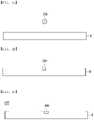
- FIGS. 1a to 1c are views showing a process of manufacturing the interior material for a vehicle according to the first embodiment of the present disclosure.
- the decorative part 500 is inserted between the nonwoven layer 200 having a thickness of 0.4 to 0.8 mm and the surface material layer 100 having a thickness of 0.4 to 0.6 mm so that the decorative part 500 and the surface material layer 100 are disposed on the nonwoven layer 200.
- the nonwoven layer 200 and the surface material layer 100 are laminated by compression with a wood press (not shown), and between the nonwoven layer 200 and the surface material layer 100, the decorative part 500 is inserted. Accordingly, the nonwoven layer 200 and the surface material layer 100 are laminated to each other to form the real material layer R.
- the nonwoven layer 200 and the surface material layer 100 are compressed with the wood press (not shown), a portion of the surface material layer 100 is formed to protrude by the decorative part 500. At this time, as the decorative part 500 is pressed by the wood press, a portion of the decorative part 500 may be inserted into the nonwoven layer 200.
- the decorative part 500 is formed by sanding the upper surface of the surface material layer 100 to expose the decorative part.
- An interior material 610 for a vehicle may be manufactured by flat molding so that the surface material layer 100 and the decorative part 500 have the same height.
- the thickness of the interior material for a vehicle is preferably 0.6 to 2.2 mm, but is not limited thereto.
- a support part 300 may be positioned under the real material layer R.
- the support part 300 may be formed on the rear surface of the surface material layer 100 and the nonwoven layer 200 while the injection material injected into the rear surface of the real material layer R is cured.
- the support part 300 fixes the surface material layer 100 to a specific object while supporting the surface material layer 100 and the nonwoven layer 200.
- FIGS. 2a to 2d Another method of manufacturing the interior material for a vehicle according to the first embodiment of the present disclosure will be described with reference to FIGS. 2a to 2d .
- FIGS. 2a to 2d are views showing another process of manufacturing the interior material for a vehicle according to the first embodiment of the present disclosure.
- a real material layer R including a surface material layer 100 and a nonwoven layer 200 in this order is prepared.
- an inlay part H that penetrates the real material layer R is formed on the real material layer R by etching or raker cutting.
- the inlay part H may correspond to a space in which the decorative part 500 is inserted into the real material layer R.
- the width of the inlay part H may be the same as or smaller than the width of the decorative part 500.
- the decorative part 500 may be fixed in the inlay part H in a press fit manner to the real material layer R.
- An interior material for a vehicle 620 is manufactured by inserting the decorative part into the inlay part H as in the step of FIG. 2c , and sanding the portion where the decorative part protrudes above the real material layer R to form the decorative part 500 as in the step of FIG. 2d .
- the inlay part H may include a known bonding means such as an adhesive so that the decorative part may be attached, and the type of the bonding means is not limited.
- the thickness of the inlay part H may be the same as the thickness of the real material layer R. Accordingly, the decorative part 500 formed in the inlay part H also has the same thickness as the thickness of the real material layer R, and the decorative part 500 is exposed on portions of the top and bottom surfaces of the real material layer R.
- the thickness of the interior material for a vehicle is preferably 0.6 to 2.2 mm, but is not limited thereto.
- FIGS. 3a to 3d Another method of manufacturing the interior material for a vehicle according to the first embodiment of the present disclosure will be described with reference to FIGS. 3a to 3d .
- FIGS. 3a to 3d are views showing yet another process of manufacturing the interior material for a vehicle according to the first embodiment of the present disclosure.
- the inlay part H is formed on the real material layer R by etching or raker cutting as in the step of FIG. 3b .
- the inlay part H of FIG. 3b may be formed in the form of a groove in the real material layer R without penetrating the real material layer.
- An interior material for a vehicle 630 is manufactured by inserting the decorative part 500 into the inlay part H as in the step of FIG. 3c , and sanding the portion where the decorative part protrudes above the real material layer R to form the decorative part 500 as in the step of FIG. 3d .
- the inlay part may include a known bonding means such as an adhesive so that the decorative part may be attached, and the type of the bonding means is not limited.
- the thickness of the inlay part H may be smaller than the thickness of the real material layer R. Accordingly, the decorative part 500 formed in the inlay part H also has a thickness smaller than the thickness of the real material layer R.
- the real material layer R includes the surface material layer 100 and the nonwoven layer 200, and the decorative part 500 may be included only in the surface material layer 100, or may be included in the surface material layer 100 and the nonwoven layer 200. At this time, the decorative part 500 is exposed on a portion of the top surface of the real material layer R, and the decorative part 500 is not exposed on the bottom surface of the real material layer.
- the thickness of the interior material for a vehicle of the embodiment is preferably 0.6 to 2.2 mm, and the thickness of the decorative part is preferably 0.4 to 0.6 mm, but is not limited thereto.
- FIGS. 4a to 4c Another method of manufacturing the interior material for a vehicle according to the first embodiment of the present disclosure will be described with reference to FIGS. 4a to 4c .
- FIGS. 4a to 4c are views showing yet another process of manufacturing the interior material for a vehicle according to the first embodiment of the present disclosure.
- the embodiment after laminating the decorative part on the upper surface of the real material layer R as in the step of FIG. 4a , compress with a wood press so that the decorative part is inserted into the real material layer by pressure as in the step of FIG. 4b .
- a separate inlay part H into which the decorative part 500 may be inserted is not formed in the real material layer R. That is, the decorative part 500 is pressed and inserted into the real material layer R without the inlay part H being formed.
- an interior material for a vehicle 650 is manufactured by sanding a portion of the decorative part 500 protruding above the real material layer R so that the surface heights of the real material layer and the decorative part are the same as in the step of FIG. 4c .
- FIGS. 5a to 5e a method of manufacturing an interior material for a vehicle according to the second embodiment of the present disclosure will be described with reference to FIGS. 5a to 5e .
- FIGS. 5a to 5e are views showing a process of manufacturing the interior material for a vehicle according to the second embodiment of the present disclosure.
- the decorative material sheet 50 is prepared as in the step of FIG. 5a .
- the decorative material sheet 50 includes the decorative part 500 and an etched part 50a.
- the decorative part 500 is formed on the decorative material sheet 50 by removing a portion of the upper part of the decorative material sheet 50, that is, the etched part 50a.
- the etched part 50a except for the decorative part 500 is removed by etching or laser cutting as in the step of 5b.
- the surface material layer 100 is laminated on the upper surface of the decorative material sheet 50 and compressed with a wood press.
- FIG. 5D a laminate of the surface material layer 100 and the decorative material sheet 50 is formed as shown in FIG. 5D .
- a portion of the surface material layer 100 located on the decorative part 500 is formed to protrude.
- an interior material for a vehicle 640 is manufactured by sanding the upper surface of the surface material layer 100 to expose the decorative part 500, and flat molding.
- the thickness of the interior material for a vehicle is preferably 0.6 to 2.2 mm, and the thickness of the surface material layer is preferably 0.4 to 0.6 mm, but is not limited thereto.
- a method of manufacturing an interior material for a vehicle of the present disclosure may further include: insert molding in an injection mold; milling using a milling jig; and coloring. If necessary, spraying a polyurethane (PU) or casting a polyurethane reactive (PUR) may also be included.
- PU polyurethane
- PUR polyurethane reactive
- the present disclosure is very economical in that there is no need to build a new facility because the existing real material automobile interior manufacturing molds and tools may be applied as it is.
- the existing mold equipment may be used as it is for wood press, insert injection, and PUR casting.
- existing jigs and fixtures such as material preparation jigs, milling jigs, and inspection tools may be used as they are.
- FIG. 1 a method of manufacturing an interior material for a vehicle according to the first embodiment of the present disclosure shown in FIG. 1 will be described with reference to FIGS. 6 to 13 .
- FIG. 6 is a flowchart illustrating a process of manufacturing the interior material for a vehicle according to the first embodiment of the present disclosure
- FIGS. 7 to 13 are views for explaining a process of manufacturing the interior material for a vehicle according to the first embodiment of the present disclosure.
- a method of manufacturing an interior material for a vehicle may include: providing S100 a surface material layer 100, a decorative part 500, and a nonwoven layer 200; bonding S200 the surface material layer 100, the decorative part 500, and the nonwoven layer 200; sanding S300 the surface material layer 100; and molding S400 the surface material layer 100, the decorative part 500, and the nonwoven layer 200 into a predetermined shape.
- a process of sanding the surface of the surface material layer 100 to a predetermined thickness so that the decorative part 500 is exposed is conducted after the bonded surface material layer 100, the decorative part 500, and the nonwoven layer 200 are flatly spread with a flat plate press 10.
- a process of sanding the surface material layer 100 to a predetermined thickness is conducted after the bonded surface material layer 100, the decorative part 500, and the nonwoven layer 200 are flatly spread with a flat plate press 10.
- the decorative part 500 is exposed in a specific pattern on the surface of the surface material layer 100, and can be used as a luxurious decoration part by a combination of wood and metal.
- the surface material layer 100 is a layer made of actual wood, and may be manufactured by thinly cutting the wood.
- the surface material layer 100 may be a veneer made of thin natural wood. These veneers may be applied to luxurious decorative parts due to the unique texture and pattern.
- the decorative part 500 is positioned under the surface material layer 100, and the decorative part 500 may be exposed from the surface material layer 100 by a sanding operation to be described later.
- the decorative part 500 may convey the feeling that the decorative part 500 is embedded in the surface material layer 100 or that a metal thin film is attached to the surface material layer 100 (see FIGS. 17 to 19 ). Since the decorative part 500 takes on a particular shape on the surface of the surface material layer 100, it may be used as a luxurious decoration by a combination of wood and metal.
- the decorative part 500 may include stainless steel, copper, aluminum, copper, or the like. However, the present disclosure is not limited thereto, and the decorative part 500 may include all metals other than the aforementioned metals. In addition to metal, the decorative part 500 may be made of a fabric material as described above.
- the decorative part 500 may represent a simple shape such as a straight line, a circle, a square, or a triangle, or a complex shape such as a specific pattern.
- the thickness of the decorative part 500 may be the same as or smaller than the thickness of the surface material layer 100 before sanding. If the thickness of the decorative part 500 is greater than the thickness of the surface material layer 100, when the decorative part 500 is bonded to the lower portion of the surface material layer 100, the protrusion height of the decorative part 500 increases, thereby increasing the amount of the decorative part 500 to be removed in the sanding process of the surface material layer 100. Accordingly, it may take a lot of time to remove the decorative part 500 in the sanding process, and thus taking a rather long time to complete the interior material for the vehicle according to the present embodiment.
- the nonwoven layer 200 may be bonded to the bottom surface of the surface material layer 100 and the decorative part 500 to fix the surface material layer 100 to another member.
- the decorative part 500 is positioned between the surface material layer 100 and the nonwoven layer 200.
- the nonwoven layer 200 may be formed of a nonwoven layer impregnated with a dedicated adhesive.
- the adhesive may be composed of one selected from the group consisting of polyvinyl acetate, phenol, melamine, urea, polyurethane, polyamide, ethylene vinyl acetate epoxy, polyester, polyvinyl alcohol, acrylonitrile butadiene rubber, styrene butadiene rubber, alkyd, acetylcellulose, and nitrocellulose.
- the nonwoven layer 200 may be formed from one or more compositions selected from the group consisting of glass fiber, carbon fiber, polyester fiber, polyamide fiber, polyurethane fiber, acrylic fiber, polyolefin fiber, polyethylene terephthalate fiber, cellulose fiber and pulp.
- the nonwoven layer 200 bonded to the surface material layer 100 is described as one sheet.
- the present disclosure is not necessarily limited thereto, and two or more nonwoven layers 200 may be bonded to the surface material layer 100 as necessary.
- two or more nonwoven layers 200 are continuously attached to the lower surface of the surface material layer 100.
- the surface material layer 100, the decorative part 500, the nonwoven layer 200, and the nonwoven layer 200 may be attached in this order.
- the surface material layer 100 and the nonwoven layer 200 are cut in advance to the same size or similar size.
- the surface material layer 100 and the nonwoven layer 200 of the same or similar size are put into the flat plate press 10 to bond the surface material layer 100 and the nonwoven layer 200 to each other.
- bonding S200 the surface material layer 100, the decorative part 500, and the nonwoven layer 200 to each other may be carried out with the flat plate press 10 having flat contact surfaces. That is, the flat plate press 10 may have flat surfaces in contact with he surface material layer 100 and the nonwoven layer 200. However, the surface of the surface material layer 100 may be formed to have a convex surface at the portion where the decorative part 500 is located due to the decorative part 500 located below the surface material layer 100.
- the flat plate press 10 is composed of an upper flat plate press 11 and a lower flat plate press 13 facing each other, and the pressure surfaces of the upper flat plate press 11 and the lower flat plate press 13 may be formed in a flat plate shape.
- the pressure surfaces indicate surfaces in which the surface material layer 100 and the nonwoven layer 200 to be bonded to each other come into contact.
- the surface material layer 100 and the nonwoven layer 200 are arranged side by side between the upper flat plate press 11 and the lower flat plate press 13. At this time, the decorative part 500 is positioned between the surface material layer 100 and the nonwoven layer 200.
- the surface material layer 100, the decorative part 500 and the nonwoven layer 200 are compressed to bond together.
- both the upper flat plate press 11 and the lower flat plate press 13 move, but it is not necessarily limited thereto and only one of the upper flat plate press 11 and the lower flat plate press 13 is not may move.
- the surface material layer 100 and the nonwoven layer 200 may be bonded to each other.
- a protective member 600 may be attached to the surface of the surface material layer 100 before bonding the surface material layer 100, the decorative part 500, and the nonwoven layer 200 with the flat plate press 10.
- the protective member 600 may prevent the surface of the surface material layer 100 from being damaged by the flat plate press 10.
- the protective member 600 may be removed from the surface of the surface material layer 100.
- the protective member 600 is described as being attached only to the surface of the surface material layer 100, but the present disclosure is not limited thereto, and the protective member 600 may also be attached to the surface of the nonwoven layer 200.
- the protective member 600 may be a silicone pad or a paper board.
- the silicone pad may be a plate having a constant thickness made of a silicone material.
- the paper board includes all thick paper, in particular, cardboard may be applied.
- the protective member 600 may have a larger area than the surface material layer 100 in order to prevent the surface material layer 100 from being damaged by the flat plate press 10.
- the protective member 600 may have an area capable of covering the entire surface of the surface material layer 100. Accordingly, when the flat plate press 10 presses the surface material layer 100 and the nonwoven layer 200, the protective member 600 having a larger area than the surface material layer 100 is applied in order to prevent the upper flat plate press 11 or the lower flat plate press 13 from directly contacting the surface material layer 100 and the nonwoven layer 200.
- the upper flat plate press 11 and the lower flat plate press 13 respectively pressurize the surface material layer 100 and the nonwoven layer 200 at a predetermined pressure for a certain period of time.
- the surface material layer 100 and the nonwoven layer 200 are closely fixed to each other while the decorative part 500 is positioned between the surface material layer 100 and the nonwoven layer 200.
- the surface material layer 100 and the nonwoven layer 200 may be formed in a flat plate shape.
- a process of sanding the surface of the surface material layer 100 may be performed.
- the surface of the surface material layer 100 is sanded using the sander 30.
- the sanding process refers to a process of finely grinding the surface of the surface material layer 100.
- the sanding process of the surface material layer 100 is not limited only to the sander 30, and various tools capable of processing the surface of the wood may be applied.
- the thickness of the surface material layer 100 may be reduced to approximately 40 to 90% of the thickness of the surface material layer 100 before sanding.
- the thickness of the surface material layer 100 may be usually 0.4 to 0.6 mm, but when the thickness of the surface material layer 100 is 0.6 mm, after the sanding process, the thickness of the surface material layer 100 may be 0.24 to 0.54 mm.
- the deformation is caused by, for example, moisture in the surface material layer 100.
- the surface material layer 100 is sanded to a certain thickness after the sanding process S300 and before the molding S400, it is possible to prevent the surface material layer 100 from being deformed during the forming or injection process.
- the thickness of the surface material layer 100 is evenly reduced.
- the surface material layer 100 may be reduced to a certain thickness.
- the thickness of the surface material layer 100 decreases and the decorative part 500 located under the surface material layer 100 is exposed.
- the decorative part 500 is exposed in a state where the surface of the surface material layer 100 is flat. That is, as shown in FIG. 17 , the unique pattern of the decorative part 500 is exposed as it is on the surface of the flat surface material layer 100.
- the surface material layer 100 to which the decorative part 500 is exposed is molded into a predetermined shape using the molding presses 31 and 33. Specifically, by disposing the surface material layer 100 and the nonwoven layer 200 between the upper molding press 31 of the intaglio form and the lower molding press 33 of the embossed form, the bonded surface material layer 100 and the nonwoven layer 200 may be molded into a predetermined shape (see FIG. 19 ).
- the upper molding press 31 and the lower molding press 33 pressurize the surface material layer 100 and the nonwoven layer 200 positioned therebetween at a constant pressure and temperature to form the surface material layer 100 and the nonwoven layer 200 into a predetermined shape.
- the surface material layer 100 and the nonwoven layer 200 are molded by directly inserting the surface material layer 100 to which the decorative part 500 is exposed into the molding presses 31 and 33.
- the surface material layer 100 and the nonwoven layer 200 may be cut to a predetermined size (see FIG. 18 ).
- various cutters such as a laser may be used.
- the molding presses 31 and 33 when molding the bonded surface material layer 100 and the nonwoven layer 200 by the molding presses 31 and 33, by positioning an additional nonwoven layer 400 under the nonwoven layer 200, the surface material layer 100, the decorative part 500, the nonwoven layer 200, and the additional nonwoven layer 400 may be laminated in this order and molded.
- the additional nonwoven layer 400 is a nonwoven layer impregnated with a dedicated adhesive, and may be made of the same material as the nonwoven layer 200 directly bonded to the surface material layer 100. Therefore, a detailed description of the additional nonwoven layer 400 will be omitted.
- injecting an injection material into the lower portion of the molded surface material layer 100 and the nonwoven layer 200 may be performed.
- the injection material is injected into the rear surface of the surface material layer 100 and the nonwoven layer 200 through an injection material feeder 60.
- a support part 300 may be formed on the rear surface of the surface material layer 100 and the nonwoven layer 200.
- the support part 300 fixes the surface material layer 100 to a specific object while supporting the surface material layer 100 and the nonwoven layer 200.
- the support part 300 may easily fix the surface material layer 100 to the inside of a vehicle.
- trimming for removing unnecessary injection material may be further performed after the injecting.
- painting may be performed on the surface of the surface material layer 100 so that the surface material layer 100 may exhibit a specific color.
- the painting may be performed by applying a stain capable of displaying a specific color on the surface of the surface material layer 100.
- the method of applying the stain to the surface of the surface material layer 100 may be to spray the stain with a spray to apply the stain to the surface material layer 100, to apply liquid stain on a sponge or the like to the surface material layer 100, or to rub solid stain onto the surface of the surface material layer 100.
- FIG. 1 Another method of manufacturing an interior material for a vehicle according to the first embodiment of the present disclosure shown in FIG. 1 will be described with reference to FIGS. 14 to 16 .
- FIGS. 14 to 16 are views for explaining another process of manufacturing the interior material for a vehicle according to the first embodiment of the present disclosure.
- a groove in which the decorative part 500 will be located may be formed in the surface material layer 100. Then, after the injecting step is completed, the decorative part 500 may be inserted and fixed into the groove formed on the surface of the surface material layer 100.
- the decorative part 500 is inserted and fixed in the surface material layer 100. That is, before the injecting step, the decorative part 500 is inserted and fixed in the surface material layer 100 by a separate process.
- the groove into which the decorative part 500 will be inserted and fixed may be simultaneously formed in the surface material layer 100 in the injecting step.
- the surface of the surface material layer 100 is brought into close contact with an upper injection mold 51 by the pressure of the injection material injected through the injection material feeder 60.
- the groove may be formed on the surface of the surface material layer 100 by a protrusion 51a formed on the upper injection mold 51. That is, the support part 300 is formed under the surface material layer 100 and the nonwoven layer 200 by the injection material, and at the same time, the groove in which the decorative part 500 is located may be formed on the surface of the surface material layer 100.
- the decorative part 500 is inserted into the groove formed on the surface of the surface material layer 100. Then, by sanding the decorative part 500 that protrudes higher than the surface of the surface material layer 100 through the sanding process, the surface material layer 100 and the decorative part 500 are processed to have the same height so that the surface of the interior material for a vehicle may be formed flat.
- the manufacturing method of the interior material for a vehicle of the present embodiment before molding into a predetermined shape by a press or the like, by sanding the surface material layer 100 immediately after bonding the surface material layer 100 and the nonwoven layer 200, it is possible to prevent the surface material layer 100 from being deformed during the molding process.
- the decorative part 500 is exposed in a specific pattern on the surface of the surface material layer 100, so that the decorative part 50 may be used as a luxurious decoration by a combination of wood and metal.
Abstract
Description
- The present disclosure relates to an interior material for a vehicle and a method for manufacturing the same.
- In general, resin molded parts are used as interior and exterior materials for automobiles, such as console boxes and panels around instrument clusters. Resin molded products are also widely used in home appliances such as cases and covers of electric rice cookers.
- In particular, various control units and convenience devices are installed on a dashboard, an audio deck, a gear shifter, an airbag, a door lock, a window control unit installed around the driver's seat and front passenger's seat inside a vehicle. In the gap between the exterior and interior materials of various control and convenience devices, finishing panels are installed as finish interior materials, and these interior materials are becoming an important factor in defining the look of a vehicle's interior.
- As such, the interior materials for automobiles have a significant effect on the aesthetics of the interior of the automobile, and thus, the aesthetic requirements for the look are gradually increasing in the current trend of individualization of automobiles.
- Accordingly, in recent years, there has been an increasing demand for interior materials for automobiles to obtain external refinement and high-quality texture.
- The present disclosure has been made keeping in mind the problems occurring in the related art. An objective of the present disclosure is to provide an interior material for a vehicle, in which heterogeneous materials such as metal or fabric are inlayed on the real material surface in real material automobile interior materials such as real wood and real carbon.
- In addition, an objective of the present disclosure is to provide a method for manufacturing an interior material for a vehicle, in which a different material such as metal or fabric is inlayed on a real material.
- Another objective of the present disclosure is to provide a method for manufacturing an interior material for a vehicle, which can prevent deformation such as shrinkage or expansion in the surface material layer in the process of manufacturing the interior material for a vehicle.
- Further, an objective of the present disclosure is to provide a method of manufacturing a luxurious interior material for a vehicle, in which the pattern of the decorative part can be exposed as it is on the surface material layer.
- An interior material for a vehicle according to an aspect of the present disclosure includes: a real material layer; and a decorative part inserted into the real material layer to expose a part thereof through a surface of the real material layer, wherein the real material layer may include one selected from a surface material layer, a nonwoven layer, and a combination thereof.
- The real material layer may further include a decorative material sheet at a bottom thereof.
- The surface material layer may be a veneer sheet or a carbon sheet.
- The nonwoven layer may include one selected from a nonwoven sheet, a glue sheet, and a combination thereof.
- The decorative part may include at least one selected from aluminum, copper, stainless steel, steel, and fabric materials.
- The thickness of the interior material for a vehicle may be 0.6 to 2.2 mm.
- A method for manufacturing an interior material for a vehicle according to an aspect of the present disclosure may include: providing a surface material layer, a decorative part, and a nonwoven layer; bonding the nonwoven layer, the decorative part, and the surface material layer in order by a flat plate press; sanding the surface material layer so that at least a portion of the decorative part is exposed; and molding the sanded nonwoven layer, the decorative part, and the surface material layer into a predetermined shape.
- In the bonding, a protective member may be disposed on at least one of an outer surface of the surface material layer and the outer surface of the nonwoven layer.
- The protective member may be a silicone pad or a paper board.
- The nonwoven layer may be impregnated with an adhesive.
- In the sanding, the thickness of the surface material layer may be reduced to 40 to 90% compared to the thickness of the surface material layer before sanding.
- After sanding the surface material layer and before the molding, the bonded surface material layer, decorative part, and nonwoven layer may be cut to a predetermined size.
- The method for manufacturing an interior material for a vehicle according to an aspect of the present disclosure may further include: injection molding of a support part located under the nonwoven layer after the molding.
- In the injection molding, an adhesive-impregnated nonwoven layer may be additionally attached under the nonwoven layer.
- A method for manufacturing an interior material for a vehicle according to an aspect of the present disclosure may include: forming an inlay part by etching or raker cutting on a real material layer in which a surface material layer and a nonwoven layer are stacked in order; inserting a decorative part into the inlay part; and sanding a protruding portion of the decorative part.
- The thickness of the inlay part may be equal to or smaller than the thickness of the real material layer.
- A method for manufacturing an interior material for a vehicle may include: removing an etched part except for a decorative part from a surface of a decorative material sheet by etching or laser cutting; laminating a surface material layer on an upper surface of the decorative material sheet prior to performing compression with a press; and exposing the decorative part by sanding the surface of the surface material layer.
- A method for manufacturing an interior material for a vehicle may include: laminating a decorative part on an upper surface of a real material layer prior to performing compression with a press; and sanding the real material layer from which the decorative part protrudes.
- The real material layer may include one selected from a surface material layer, a nonwoven layer, and a combination thereof.
- The surface material layer may be a veneer sheet or a carbon sheet.
- The decorative part may include at least one selected from aluminum, copper, stainless steel, steel, and fabric materials.
- As described above, the method for manufacturing an interior material for a vehicle according to an aspect of the present disclosure can prevent deformation such as shrinkage or expansion in the surface material layer during the manufacturing process.
- In addition, the interior material for a vehicle manufactured by the method for manufacturing an interior material for a vehicle according to an aspect of the present disclosure can be used as a luxurious decoration by exposing a specific pattern of the decorative part on the surface of the surface material layer as it is.
- Moreover, in the case of the interior material for a vehicle manufactured by the method for manufacturing an interior material for a vehicle according to an aspect of the present disclosure, by utilizing inlays in conventional real wood or real carbon products, it is possible to provide more sophisticated, luxurious, and varied aesthetics.
- Further, in the case of the interior material for a vehicle manufactured by the method for manufacturing an interior material for a vehicle according to an aspect of the present disclosure, existing molds and jigs and fixtures can be applied as they are, so no extra cost is required to build facilities, making it economical and efficient.
-
-
FIGS. 1a to 1c are views showing a process of manufacturing an interior material for a vehicle according to a first embodiment of the present disclosure; -
FIGS. 2a to 2d are views showing another process of manufacturing the interior material for a vehicle according to the first embodiment of the present disclosure; -
FIGS. 3a to 3d are views showing yet another process of manufacturing the interior material for a vehicle according to the first embodiment of the present disclosure; -
FIGS. 4a to 4c are views showing yet another process of manufacturing the interior material for a vehicle according to the first embodiment of the present disclosure; -
FIGS. 5a to 5e are views showing yet another process of manufacturing an interior material for a vehicle according to a second embodiment of the present disclosure; -
FIG. 6 is a flowchart illustrating a process of manufacturing the interior material for a vehicle according to the first embodiment of the present disclosure; -
FIGS. 7 to 13 are views for explaining a process of manufacturing the interior material for a vehicle according to the first embodiment of the present disclosure; -
FIGS. 14 to 16 are views for explaining another process of manufacturing the interior material for a vehicle according to the first embodiment of the present disclosure; -
FIG. 17 is a photograph of an interior material for a vehicle in which the surface of a surface material layer is sanded so that a decorative part is exposed; -
FIG. 18 is a photograph taken of an interior material for a vehicle laser cut before molding into a predetermined shape; and -
FIG. 19 is a photograph taken of an interior material for a vehicle molded by a press. - While the present disclosure may be modified in various ways and take on various alternative forms, specific embodiments thereof are shown and described in detail below. However, it should be understood that there is no intent to limit the present disclosure to the particular forms disclosed, but on the contrary, the present disclosure covers all modifications, equivalents, and alternatives falling within the spirit and scope of the present disclosure.
- The terminology used herein to describe embodiments of the present disclosure is not intended to limit the scope of the present disclosure. The singular expression includes the plural expression unless the context clearly dictates otherwise. It should be further understood that the terms "comprise", "include", and/or "have", when used herein, specify the presence of stated features, numbers, steps, operations, elements, components, and/or groups thereof but do not preclude the presence or addition of one or more other features, numbers, steps, operations, elements, components, and/or groups thereof.
- Hereinafter, preferred embodiments of the present disclosure will be described in detail with reference to the accompanying drawings. In this case, it should be noted that in the accompanying drawings, the same components are denoted by the same reference numerals as much as possible. In addition, detailed descriptions of well-known functions and configurations that may obscure the gist of the present disclosure will be omitted. For the same reason, some components are exaggerated, omitted, or schematically illustrated in the accompanying drawings.
- Hereinafter, an interior material for a vehicle according to a first embodiment of the present disclosure will be described.
-
FIGS. 1a to 1c are views showing a process of manufacturing an interior material for a vehicle according to a first embodiment of the present disclosure;FIGS. 2a to 2d are views showing another process of manufacturing the interior material for a vehicle according to the first embodiment of the present disclosure;FIGS. 3a to 3d are views showing yet another process of manufacturing the interior material for a vehicle according to the first embodiment of the present disclosure; andFIGS. 4a to 4c are views showing yet another process of manufacturing the interior material for a vehicle according to the first embodiment of the present disclosure. - Referring to
FIGS. 1 to 4 , the interior material for a vehicle according to the first embodiment of the present disclosure may include a real material layer R and adecorative part 500. According to the embodiment, thedecorative part 500 may be exposed on the surface of the real material layer R. Thereby, it is possible to implement various textures, senses of depth and design in the interior material for a vehicle, and there is an effect of further enhancing the sense of quality of the real interior materials. - The real material layer R may include one selected from a
surface material layer 100, anonwoven layer 200, and a combination thereof. More specifically, the real material layer R may include only thesurface material layer 100. Alternatively, the real material layer R may include thesurface material layer 100 and thenonwoven layer 200. - The
surface material layer 100 may be a veneer sheet or a carbon sheet. By including veneer or carbon sheet, natural patterns may be maximized and a sense of depth may be realized, and it is possible to meet eco-friendly trends and show a luxurious appearance. - For example, the
surface material layer 100 is a layer made of actual wood, and may be manufactured by thinly cutting the wood. Thesurface material layer 100 may be a veneer sheet made of thin natural wood. These veneers may be applied to luxurious decorative materials due to the unique texture and pattern of the veneer. - According to the embodiment, the
decorative part 500 may be partially exposed on the surface of the real material layer R. Meanwhile, thedecorative part 500 may not be exposed on the lower surface of the real material layer R, or some or all of thedecorative part 500 may be exposed. - Here, as shown in
FIG. 1c , thedecorative part 500 may be included only in thesurface material layer 100. Alternatively, thedecorative part 500 may be included in thesurface material layer 100 and thenonwoven layer 200. That is, thedecorative part 500 may extend through thesurface material layer 100 to thenonwoven layer 200. - The
decorative part 500 is positioned under thesurface material layer 100, and thedecorative part 500 may be exposed from thesurface material layer 100 by a sanding operation or the like. - As the
decorative part 500 is exposed from thesurface material layer 100, thedecorative part 500 may convey the feeling that thedecorative part 500 is embedded in thesurface material layer 100 or that a metal thin film is attached to the surface material layer 100 (seeFIGS. 17 to 19 ). Since thedecorative part 500 takes on a particular shape on the surface of thesurface material layer 100, it may be used as a luxurious decoration by a combination of wood and metal. - The
decorative part 500 may include at least one selected from metal materials such as aluminum, copper, stainless steel (SUS), and steel and fabric materials. - When processes such as etching or laser cutting are undertaken, any fabric material including general cloth or fabric may be selected and used without limitation, but a fabric with high strength may be selected and used according to the characteristics of the manufacturing method. In this case, the strength of the fabric is preferably as strong as bamboo and includes hard fibers.
- By applying a material different from the
surface material layer 100 of the real material layer to thedecorative part 500, that is, by mixing different materials such as wood and metal, carbon and metal, wood and fabric, or carbon and fabric, various textures, sense of depths, and designs may be implemented in the interior material of the vehicle, further enhancing the sense of quality of car interior material made of real materials. - According to the embodiment, the
decorative part 500 may represent a simple shape such as a straight line, a circle, a square, or a triangle, or a complex shape such as a specific pattern. - At least one of the horizontal and vertical lengths of the
decorative part 500 is smaller than the length of at least any one of the horizontal and vertical lengths of the real material layer R. That is, thedecorative part 500 may be included in the real material layer R in the form of a strip. - Meanwhile, the thickness of the
decorative part 500 may be the same as or smaller than the thickness of thesurface material layer 100 before sanding. If the thickness of thedecorative part 500 is greater than the thickness of thesurface material layer 100, when thedecorative part 500 is bonded to the lower portion of thesurface material layer 100, the protrusion height of thedecorative part 500 increases, thereby increasing the amount of thedecorative part 500 to be removed in the sanding process of thesurface material layer 100. Accordingly, it may take a lot of time to remove thedecorative part 500 in the sanding process, and thus taking a rather long time to complete the interior material for the vehicle according to the present embodiment. - The
nonwoven layer 200 may be formed of a nonwoven layer impregnated with a dedicated adhesive. Here, the adhesive may be composed of one selected from the group consisting of polyvinyl acetate, phenol, melamine, urea, polyurethane, polyamide, ethylene vinyl acetate epoxy, polyester, polyvinyl alcohol, acrylonitrile butadiene rubber, styrene butadiene rubber, alkyd, acetylcellulose, and nitrocellulose. - The
nonwoven layer 200 may be formed from one or more compositions selected from the group consisting of glass fiber, carbon fiber, polyester fiber, polyamide fiber, polyurethane fiber, acrylic fiber, polyolefin fiber, polyethylene terephthalate fiber, cellulose fiber and pulp. - Meanwhile, a support part 300 (see
FIG. 13 ) may be positioned under the real material layer R. Thesupport part 300 may be formed on the rear surface of thesurface material layer 100 and thenonwoven layer 200 while the injection molding material injected into the rear surface of the real material layer R is cured. Thesupport part 300 fixes thesurface material layer 100 to a specific object while supporting thesurface material layer 100 and thenonwoven layer 200. For example, thesupport part 300 may easily fix thesurface material layer 100 to the interior of the vehicle. At this time, thesupport part 300 may have a thickness of 3.3 to 3.7 mm, but is not limited within the above range. - The thickness of the interior material for a vehicle of the present disclosure may be 0.6 to 2.2 mm except for the
support part 300. This is a thickness after compression by a wood press, and is not limited within the above range and may be formed in various thicknesses. - The interior material for a vehicle of the present disclosure may further include a coating layer on the top. The coating layer may be formed through PUR casting, and may have a thickness of 0.7 to 1.0 mm, but is not limited within the above range.
- Hereinafter, an interior material for a vehicle according to a second embodiment of the present disclosure will be described.
-
FIG. 5 is a view showing a process of manufacturing an interior material for a vehicle according to a second embodiment of the present disclosure. - Referring to
FIG. 5 , the interior material for a vehicle according to the second embodiment of the present disclosure includes asurface material layer 100,decorative material sheet 50, and adecorative part 500, and thedecorative part 500 may be exposed on the surface of thesurface material layer 100 in the same manner as the interior material for a vehicle according to the first embodiment described above. At this time, thedecorative material sheet 50 is located under thesurface material layer 100, thedecorative part 500 is formed in a shape protruding from the surface of thedecorative material sheet 50, and thedecorative part 500 and thedecorative material sheet 50 are formed integrally. According to the second embodiment, thedecorative part 500 may be formed by etching or laser cutting a portion of thedecorative material sheet 50. A detailed description thereof will be provided later. - Hereinafter, the interior material for a vehicle according to the first embodiment of the present disclosure will be described.
-
FIGS. 1a to 1c are views showing a process of manufacturing the interior material for a vehicle according to the first embodiment of the present disclosure. - According to the embodiment, as in
FIG. 1a , thedecorative part 500 is inserted between thenonwoven layer 200 having a thickness of 0.4 to 0.8 mm and thesurface material layer 100 having a thickness of 0.4 to 0.6 mm so that thedecorative part 500 and thesurface material layer 100 are disposed on thenonwoven layer 200. - Then, as in the step of
FIG. 1b , thenonwoven layer 200 and thesurface material layer 100 are laminated by compression with a wood press (not shown), and between thenonwoven layer 200 and thesurface material layer 100, thedecorative part 500 is inserted. Accordingly, thenonwoven layer 200 and thesurface material layer 100 are laminated to each other to form the real material layer R. - When the
nonwoven layer 200 and thesurface material layer 100 are compressed with the wood press (not shown), a portion of thesurface material layer 100 is formed to protrude by thedecorative part 500. At this time, as thedecorative part 500 is pressed by the wood press, a portion of thedecorative part 500 may be inserted into thenonwoven layer 200. - In the embodiment, as in the step of
FIG. 1c , thedecorative part 500 is formed by sanding the upper surface of thesurface material layer 100 to expose the decorative part. Aninterior material 610 for a vehicle may be manufactured by flat molding so that thesurface material layer 100 and thedecorative part 500 have the same height. The thickness of the interior material for a vehicle is preferably 0.6 to 2.2 mm, but is not limited thereto. - Meanwhile, a support part 300 (see
FIG. 13 ) may be positioned under the real material layer R. Thesupport part 300 may be formed on the rear surface of thesurface material layer 100 and thenonwoven layer 200 while the injection material injected into the rear surface of the real material layer R is cured. Thesupport part 300 fixes thesurface material layer 100 to a specific object while supporting thesurface material layer 100 and thenonwoven layer 200. - Hereinafter, another method of manufacturing the interior material for a vehicle according to the first embodiment of the present disclosure will be described with reference to
FIGS. 2a to 2d . -
FIGS. 2a to 2d are views showing another process of manufacturing the interior material for a vehicle according to the first embodiment of the present disclosure. - According to the embodiment, as in the step of
FIG. 2a , a real material layer R including asurface material layer 100 and anonwoven layer 200 in this order is prepared. - Then, as in
FIG. 2b , an inlay part H that penetrates the real material layer R is formed on the real material layer R by etching or raker cutting. The inlay part H may correspond to a space in which thedecorative part 500 is inserted into the real material layer R. The width of the inlay part H may be the same as or smaller than the width of thedecorative part 500. Thereby, thedecorative part 500 may be fixed in the inlay part H in a press fit manner to the real material layer R. - An interior material for a
vehicle 620 is manufactured by inserting the decorative part into the inlay part H as in the step ofFIG. 2c , and sanding the portion where the decorative part protrudes above the real material layer R to form thedecorative part 500 as in the step ofFIG. 2d . The inlay part H may include a known bonding means such as an adhesive so that the decorative part may be attached, and the type of the bonding means is not limited. - Here, the thickness of the inlay part H may be the same as the thickness of the real material layer R. Accordingly, the
decorative part 500 formed in the inlay part H also has the same thickness as the thickness of the real material layer R, and thedecorative part 500 is exposed on portions of the top and bottom surfaces of the real material layer R. The thickness of the interior material for a vehicle is preferably 0.6 to 2.2 mm, but is not limited thereto. - Hereinafter, another method of manufacturing the interior material for a vehicle according to the first embodiment of the present disclosure will be described with reference to
FIGS. 3a to 3d . -
FIGS. 3a to 3d are views showing yet another process of manufacturing the interior material for a vehicle according to the first embodiment of the present disclosure. - According to the embodiment, as in the step of
FIG. 3a , after preparing the real material layer R including thesurface material layer 100 and thenonwoven layer 200 in order, the inlay part H is formed on the real material layer R by etching or raker cutting as in the step ofFIG. 3b . Unlike inFIG. 2 , the inlay part H ofFIG. 3b may be formed in the form of a groove in the real material layer R without penetrating the real material layer. - An interior material for a
vehicle 630 is manufactured by inserting thedecorative part 500 into the inlay part H as in the step ofFIG. 3c , and sanding the portion where the decorative part protrudes above the real material layer R to form thedecorative part 500 as in the step ofFIG. 3d . The inlay part may include a known bonding means such as an adhesive so that the decorative part may be attached, and the type of the bonding means is not limited. - Here, the thickness of the inlay part H may be smaller than the thickness of the real material layer R. Accordingly, the
decorative part 500 formed in the inlay part H also has a thickness smaller than the thickness of the real material layer R. The real material layer R includes thesurface material layer 100 and thenonwoven layer 200, and thedecorative part 500 may be included only in thesurface material layer 100, or may be included in thesurface material layer 100 and thenonwoven layer 200. At this time, thedecorative part 500 is exposed on a portion of the top surface of the real material layer R, and thedecorative part 500 is not exposed on the bottom surface of the real material layer. - The thickness of the interior material for a vehicle of the embodiment is preferably 0.6 to 2.2 mm, and the thickness of the decorative part is preferably 0.4 to 0.6 mm, but is not limited thereto.
- Hereinafter, another method of manufacturing the interior material for a vehicle according to the first embodiment of the present disclosure will be described with reference to
FIGS. 4a to 4c . -
FIGS. 4a to 4c are views showing yet another process of manufacturing the interior material for a vehicle according to the first embodiment of the present disclosure. - According to the embodiment, after laminating the decorative part on the upper surface of the real material layer R as in the step of
FIG. 4a , compress with a wood press so that the decorative part is inserted into the real material layer by pressure as in the step ofFIG. 4b . Unlike the manufacturing method described previously, in this manufacturing method, a separate inlay part H into which thedecorative part 500 may be inserted is not formed in the real material layer R. That is, thedecorative part 500 is pressed and inserted into the real material layer R without the inlay part H being formed. - Then, an interior material for a
vehicle 650 is manufactured by sanding a portion of thedecorative part 500 protruding above the real material layer R so that the surface heights of the real material layer and the decorative part are the same as in the step ofFIG. 4c . - Hereinafter, a method of manufacturing an interior material for a vehicle according to the second embodiment of the present disclosure will be described with reference to
FIGS. 5a to 5e . -
FIGS. 5a to 5e are views showing a process of manufacturing the interior material for a vehicle according to the second embodiment of the present disclosure. - In this embodiment, the
decorative material sheet 50 is prepared as in the step ofFIG. 5a . Thedecorative material sheet 50 includes thedecorative part 500 and anetched part 50a. In this embodiment, thedecorative part 500 is formed on thedecorative material sheet 50 by removing a portion of the upper part of thedecorative material sheet 50, that is, theetched part 50a. - More specifically, the
etched part 50a except for thedecorative part 500 is removed by etching or laser cutting as in the step of 5b. - As in the step of
FIG. 5c , after theetched part 50a is removed, thesurface material layer 100 is laminated on the upper surface of thedecorative material sheet 50 and compressed with a wood press. - Thereby, a laminate of the
surface material layer 100 and thedecorative material sheet 50 is formed as shown inFIG. 5D . Here, a portion of thesurface material layer 100 located on thedecorative part 500 is formed to protrude. - As in the step of
FIG. 5e , an interior material for avehicle 640 is manufactured by sanding the upper surface of thesurface material layer 100 to expose thedecorative part 500, and flat molding. - The thickness of the interior material for a vehicle is preferably 0.6 to 2.2 mm, and the thickness of the surface material layer is preferably 0.4 to 0.6 mm, but is not limited thereto.
- A method of manufacturing an interior material for a vehicle of the present disclosure may further include: insert molding in an injection mold; milling using a milling jig; and coloring. If necessary, spraying a polyurethane (PU) or casting a polyurethane reactive (PUR) may also be included.
- The present disclosure is very economical in that there is no need to build a new facility because the existing real material automobile interior manufacturing molds and tools may be applied as it is. Specifically, the existing mold equipment may be used as it is for wood press, insert injection, and PUR casting. In addition, existing jigs and fixtures such as material preparation jigs, milling jigs, and inspection tools may be used as they are.
- Hereinafter, a method of manufacturing an interior material for a vehicle according to the first embodiment of the present disclosure shown in
FIG. 1 will be described with reference toFIGS. 6 to 13 . -
FIG. 6 is a flowchart illustrating a process of manufacturing the interior material for a vehicle according to the first embodiment of the present disclosure; andFIGS. 7 to 13 are views for explaining a process of manufacturing the interior material for a vehicle according to the first embodiment of the present disclosure. - Referring to
FIGS. 6 to 13 , a method of manufacturing an interior material for a vehicle according to the first embodiment of the present disclosure may include: providing S100 asurface material layer 100, adecorative part 500, and anonwoven layer 200; bonding S200 thesurface material layer 100, thedecorative part 500, and thenonwoven layer 200; sanding S300 thesurface material layer 100; and molding S400 thesurface material layer 100, thedecorative part 500, and thenonwoven layer 200 into a predetermined shape. - According to the embodiment, before molding into a predetermined shape, a process of sanding the surface of the
surface material layer 100 to a predetermined thickness so that thedecorative part 500 is exposed is conducted after the bondedsurface material layer 100, thedecorative part 500, and thenonwoven layer 200 are flatly spread with aflat plate press 10. As described, by sanding thesurface material layer 100 to a predetermined thickness, it is possible to prevent thesurface material layer 100 from being deformed during the molding process. Moreover, thedecorative part 500 is exposed in a specific pattern on the surface of thesurface material layer 100, and can be used as a luxurious decoration part by a combination of wood and metal. - Referring to
FIG. 7 , thesurface material layer 100 is a layer made of actual wood, and may be manufactured by thinly cutting the wood. Thesurface material layer 100 may be a veneer made of thin natural wood. These veneers may be applied to luxurious decorative parts due to the unique texture and pattern. - The
decorative part 500 is positioned under thesurface material layer 100, and thedecorative part 500 may be exposed from thesurface material layer 100 by a sanding operation to be described later. - As the
decorative part 500 is exposed from thesurface material layer 100, thedecorative part 500 may convey the feeling that thedecorative part 500 is embedded in thesurface material layer 100 or that a metal thin film is attached to the surface material layer 100 (seeFIGS. 17 to 19 ). Since thedecorative part 500 takes on a particular shape on the surface of thesurface material layer 100, it may be used as a luxurious decoration by a combination of wood and metal. - The
decorative part 500 may include stainless steel, copper, aluminum, copper, or the like. However, the present disclosure is not limited thereto, and thedecorative part 500 may include all metals other than the aforementioned metals. In addition to metal, thedecorative part 500 may be made of a fabric material as described above. - According to the embodiment, the
decorative part 500 may represent a simple shape such as a straight line, a circle, a square, or a triangle, or a complex shape such as a specific pattern. - Meanwhile, the thickness of the
decorative part 500 may be the same as or smaller than the thickness of thesurface material layer 100 before sanding. If the thickness of thedecorative part 500 is greater than the thickness of thesurface material layer 100, when thedecorative part 500 is bonded to the lower portion of thesurface material layer 100, the protrusion height of thedecorative part 500 increases, thereby increasing the amount of thedecorative part 500 to be removed in the sanding process of thesurface material layer 100. Accordingly, it may take a lot of time to remove thedecorative part 500 in the sanding process, and thus taking a rather long time to complete the interior material for the vehicle according to the present embodiment. - The
nonwoven layer 200 may be bonded to the bottom surface of thesurface material layer 100 and thedecorative part 500 to fix thesurface material layer 100 to another member. Here, thedecorative part 500 is positioned between thesurface material layer 100 and thenonwoven layer 200. - The
nonwoven layer 200 may be formed of a nonwoven layer impregnated with a dedicated adhesive. Here, the adhesive may be composed of one selected from the group consisting of polyvinyl acetate, phenol, melamine, urea, polyurethane, polyamide, ethylene vinyl acetate epoxy, polyester, polyvinyl alcohol, acrylonitrile butadiene rubber, styrene butadiene rubber, alkyd, acetylcellulose, and nitrocellulose. - The
nonwoven layer 200 may be formed from one or more compositions selected from the group consisting of glass fiber, carbon fiber, polyester fiber, polyamide fiber, polyurethane fiber, acrylic fiber, polyolefin fiber, polyethylene terephthalate fiber, cellulose fiber and pulp. - According to the embodiment, the
nonwoven layer 200 bonded to thesurface material layer 100 is described as one sheet. However, the present disclosure is not necessarily limited thereto, and two or morenonwoven layers 200 may be bonded to thesurface material layer 100 as necessary. When two or morenonwoven layers 200 are bonded to thesurface material layer 100, two or morenonwoven layers 200 are continuously attached to the lower surface of thesurface material layer 100. For example, thesurface material layer 100, thedecorative part 500, thenonwoven layer 200, and thenonwoven layer 200 may be attached in this order. - Before bonding the
surface material layer 100 and thenonwoven layer 200 to each other, thesurface material layer 100 and thenonwoven layer 200 are cut in advance to the same size or similar size. Thesurface material layer 100 and thenonwoven layer 200 of the same or similar size are put into theflat plate press 10 to bond thesurface material layer 100 and thenonwoven layer 200 to each other. - Referring to
FIG. 8 , bonding S200 thesurface material layer 100, thedecorative part 500, and thenonwoven layer 200 to each other may be carried out with theflat plate press 10 having flat contact surfaces. That is, theflat plate press 10 may have flat surfaces in contact with he surfacematerial layer 100 and thenonwoven layer 200. However, the surface of thesurface material layer 100 may be formed to have a convex surface at the portion where thedecorative part 500 is located due to thedecorative part 500 located below thesurface material layer 100. - The
flat plate press 10 is composed of an upperflat plate press 11 and a lowerflat plate press 13 facing each other, and the pressure surfaces of the upperflat plate press 11 and the lowerflat plate press 13 may be formed in a flat plate shape. Here, the pressure surfaces indicate surfaces in which thesurface material layer 100 and thenonwoven layer 200 to be bonded to each other come into contact. - The
surface material layer 100 and thenonwoven layer 200 are arranged side by side between the upperflat plate press 11 and the lowerflat plate press 13. At this time, thedecorative part 500 is positioned between thesurface material layer 100 and thenonwoven layer 200. - Thereafter, as the upper
flat plate press 11 and the lowerflat plate press 13 move toward each other, thesurface material layer 100, thedecorative part 500 and thenonwoven layer 200 are compressed to bond together. In this embodiment, it is described that both the upperflat plate press 11 and the lowerflat plate press 13 move, but it is not necessarily limited thereto and only one of the upperflat plate press 11 and the lowerflat plate press 13 is not may move. For example, while the upperflat plate press 11 moves toward the lowerflat plate press 13, thesurface material layer 100 and thenonwoven layer 200 may be bonded to each other. - According to the embodiment, a
protective member 600 may be attached to the surface of thesurface material layer 100 before bonding thesurface material layer 100, thedecorative part 500, and thenonwoven layer 200 with theflat plate press 10. Theprotective member 600 may prevent the surface of thesurface material layer 100 from being damaged by theflat plate press 10. When thesurface material layer 100 and thenonwoven layer 200 are attached to each other by theflat plate press 10, theprotective member 600 may be removed from the surface of thesurface material layer 100. - In
FIG. 8 , theprotective member 600 is described as being attached only to the surface of thesurface material layer 100, but the present disclosure is not limited thereto, and theprotective member 600 may also be attached to the surface of thenonwoven layer 200. - Here, the
protective member 600 may be a silicone pad or a paper board. The silicone pad may be a plate having a constant thickness made of a silicone material. The paper board includes all thick paper, in particular, cardboard may be applied. - According to the embodiment, the
protective member 600 may have a larger area than thesurface material layer 100 in order to prevent thesurface material layer 100 from being damaged by theflat plate press 10. In other words, theprotective member 600 may have an area capable of covering the entire surface of thesurface material layer 100. Accordingly, when theflat plate press 10 presses thesurface material layer 100 and thenonwoven layer 200, theprotective member 600 having a larger area than thesurface material layer 100 is applied in order to prevent the upperflat plate press 11 or the lowerflat plate press 13 from directly contacting thesurface material layer 100 and thenonwoven layer 200. - When the
flat plate press 10 bonds thesurface material layer 100 and thenonwoven layer 200 to each other, the upperflat plate press 11 and the lowerflat plate press 13 respectively pressurize thesurface material layer 100 and thenonwoven layer 200 at a predetermined pressure for a certain period of time. - As such, when bonding of the
surface material layer 100 and thenonwoven layer 200 by theflat plate press 10 is completed, thesurface material layer 100 and thenonwoven layer 200 are closely fixed to each other while thedecorative part 500 is positioned between thesurface material layer 100 and thenonwoven layer 200. In addition, thesurface material layer 100 and thenonwoven layer 200 may be formed in a flat plate shape. - In the embodiment, when the
surface material layer 100 and thenonwoven layer 200 are flatly bonded by theflat plate press 10, it is easy to sand the surface of thesurface material layer 100 to a constant thickness with asander 30 to be described later. A detailed description thereof will be provided later. - Referring to
FIG. 9 , after thesurface material layer 100 and thenonwoven layer 200 are bonded with thedecorative part 500 interposed therebetween, a process of sanding the surface of thesurface material layer 100 may be performed. In this embodiment, the surface of thesurface material layer 100 is sanded using thesander 30. Here, the sanding process refers to a process of finely grinding the surface of thesurface material layer 100. However, the sanding process of thesurface material layer 100 is not limited only to thesander 30, and various tools capable of processing the surface of the wood may be applied. - According to the embodiment, after the sanding process S300, the thickness of the
surface material layer 100 may be reduced to approximately 40 to 90% of the thickness of thesurface material layer 100 before sanding. For example, after thesurface material layer 100 and thenonwoven layer 200 are bonded by theflat plate press 10, the thickness of thesurface material layer 100 may be usually 0.4 to 0.6 mm, but when the thickness of thesurface material layer 100 is 0.6 mm, after the sanding process, the thickness of thesurface material layer 100 may be 0.24 to 0.54 mm. - In general, the thicker the
surface material layer 100 is, more frequently deformation such as shrinkage or expansion of thesurface material layer 100 occurs when thesurface material layer 100 is molded by molding presses 31 and 33 or an injection material is bonded to thesurface material layer 100 by injection molding. The deformation is caused by, for example, moisture in thesurface material layer 100. - Therefore, as in this embodiment, if the
surface material layer 100 is sanded to a certain thickness after the sanding process S300 and before the molding S400, it is possible to prevent thesurface material layer 100 from being deformed during the forming or injection process. - In the embodiment, as the
sander 30 moves the surface of the bondedsurface material layer 100, the thickness of thesurface material layer 100 is evenly reduced. By the sanding operation of thesander 30, thesurface material layer 100 may be reduced to a certain thickness. - When the surface of the
surface material layer 100 is sanded by thesander 30, the thickness of thesurface material layer 100 decreases and thedecorative part 500 located under thesurface material layer 100 is exposed. When this sanding process S300 is completed, thedecorative part 500 is exposed in a state where the surface of thesurface material layer 100 is flat. That is, as shown inFIG. 17 , the unique pattern of thedecorative part 500 is exposed as it is on the surface of the flatsurface material layer 100. - Referring to
FIG. 10 , when the sanding operation S300 of thesurface material layer 100 is completed, thesurface material layer 100 to which thedecorative part 500 is exposed is molded into a predetermined shape using the molding presses 31 and 33. Specifically, by disposing thesurface material layer 100 and thenonwoven layer 200 between theupper molding press 31 of the intaglio form and thelower molding press 33 of the embossed form, the bondedsurface material layer 100 and thenonwoven layer 200 may be molded into a predetermined shape (seeFIG. 19 ). - The
upper molding press 31 and thelower molding press 33 pressurize thesurface material layer 100 and thenonwoven layer 200 positioned therebetween at a constant pressure and temperature to form thesurface material layer 100 and thenonwoven layer 200 into a predetermined shape. - In the embodiment, the
surface material layer 100 and thenonwoven layer 200 are molded by directly inserting thesurface material layer 100 to which thedecorative part 500 is exposed into the molding presses 31 and 33. However, before thesurface material layer 100 and thenonwoven layer 200 are put into the molding presses 31 and 33, thesurface material layer 100 and thenonwoven layer 200 may be cut to a predetermined size (seeFIG. 18 ). At this time, in order to cut thesurface material layer 100 and thenonwoven layer 200, various cutters such as a laser may be used. - Referring to
FIG. 11 , when molding the bondedsurface material layer 100 and thenonwoven layer 200 by the molding presses 31 and 33, by positioning an additionalnonwoven layer 400 under thenonwoven layer 200, thesurface material layer 100, thedecorative part 500, thenonwoven layer 200, and the additionalnonwoven layer 400 may be laminated in this order and molded. - Here, the additional
nonwoven layer 400 is a nonwoven layer impregnated with a dedicated adhesive, and may be made of the same material as thenonwoven layer 200 directly bonded to thesurface material layer 100. Therefore, a detailed description of the additionalnonwoven layer 400 will be omitted. - Referring to
FIG. 12 , when the molding S400 is completed, injecting an injection material into the lower portion of the moldedsurface material layer 100 and thenonwoven layer 200 may be performed. In the injecting, after putting thesurface material layer 100 and thenonwoven layer 200 molded into a predetermined shape intoinjection molds surface material layer 100 and thenonwoven layer 200 through aninjection material feeder 60. - As a result, while the injection material injected into the rear surface of the
nonwoven layer 200 is cured, asupport part 300 may be formed on the rear surface of thesurface material layer 100 and thenonwoven layer 200. Thesupport part 300 fixes thesurface material layer 100 to a specific object while supporting thesurface material layer 100 and thenonwoven layer 200. For example, thesupport part 300 may easily fix thesurface material layer 100 to the inside of a vehicle. - Thereafter, trimming for removing unnecessary injection material may be further performed after the injecting.
- Referring to
FIG. 13 , when the injecting is completed, painting may be performed on the surface of thesurface material layer 100 so that thesurface material layer 100 may exhibit a specific color. The painting may be performed by applying a stain capable of displaying a specific color on the surface of thesurface material layer 100. At this time, the method of applying the stain to the surface of thesurface material layer 100 may be to spray the stain with a spray to apply the stain to thesurface material layer 100, to apply liquid stain on a sponge or the like to thesurface material layer 100, or to rub solid stain onto the surface of thesurface material layer 100. - Hereinafter, another method of manufacturing an interior material for a vehicle according to the first embodiment of the present disclosure shown in
FIG. 1 will be described with reference toFIGS. 14 to 16 . -
FIGS. 14 to 16 are views for explaining another process of manufacturing the interior material for a vehicle according to the first embodiment of the present disclosure. - Referring to
FIGS. 14 to 16 , according to the embodiment, in the injecting step of forming thesupport part 300 under thesurface material layer 100 and thenonwoven layer 200, a groove in which thedecorative part 500 will be located may be formed in thesurface material layer 100. Then, after the injecting step is completed, thedecorative part 500 may be inserted and fixed into the groove formed on the surface of thesurface material layer 100. - In the manufacturing method of the interior material for a vehicle shown in the above-mentioned
FIGS. 5 to 12 , before performing the injecting step of injecting the injection material, thedecorative part 500 is inserted and fixed in thesurface material layer 100. That is, before the injecting step, thedecorative part 500 is inserted and fixed in thesurface material layer 100 by a separate process. - However, in this embodiment, without inserting the
decorative part 500 on the surface of thesurface material layer 100 before the injecting step, the groove into which thedecorative part 500 will be inserted and fixed may be simultaneously formed in thesurface material layer 100 in the injecting step. - According to this embodiment, as shown in
FIG. 15 , the surface of thesurface material layer 100 is brought into close contact with anupper injection mold 51 by the pressure of the injection material injected through theinjection material feeder 60. At this time, the groove may be formed on the surface of thesurface material layer 100 by aprotrusion 51a formed on theupper injection mold 51. That is, thesupport part 300 is formed under thesurface material layer 100 and thenonwoven layer 200 by the injection material, and at the same time, the groove in which thedecorative part 500 is located may be formed on the surface of thesurface material layer 100. - Thereafter, as shown in
FIG. 16 , thedecorative part 500 is inserted into the groove formed on the surface of thesurface material layer 100. Then, by sanding thedecorative part 500 that protrudes higher than the surface of thesurface material layer 100 through the sanding process, thesurface material layer 100 and thedecorative part 500 are processed to have the same height so that the surface of the interior material for a vehicle may be formed flat. - According to the manufacturing method of the interior material for a vehicle of the present embodiment, before molding into a predetermined shape by a press or the like, by sanding the
surface material layer 100 immediately after bonding thesurface material layer 100 and thenonwoven layer 200, it is possible to prevent thesurface material layer 100 from being deformed during the molding process. In addition, thedecorative part 500 is exposed in a specific pattern on the surface of thesurface material layer 100, so that thedecorative part 50 may be used as a luxurious decoration by a combination of wood and metal. - In the above, an embodiment of the present disclosure has been described, however, those of ordinary skill in the art will be able to variously modify and change the present disclosure by supplementing, changing, deleting, or adding components within the scope that does not depart from the spirit of the present disclosure described in the claims, and this will also be included within the scope of the present disclosure.
Claims (21)
- An interior material for a vehicle, comprising:a real material layer; anda decorative part inserted into the real material layer to expose a part thereof through a surface of the real material layer,wherein the real material layer includes one selected from a surface material layer, a nonwoven layer, and a combination thereof.
- The interior material for a vehicle of claim 1, wherein the real material layer further includes a decorative material sheet at a bottom thereof.
- The interior material for a vehicle of claim 1, wherein the surface material layer is a veneer sheet or a carbon sheet.
- The interior material for a vehicle of claim 1, wherein the nonwoven layer includes any one selected from a nonwoven sheet, a glue sheet, and a combination thereof.
- The interior material for a vehicle of claim 1, wherein the decorative part includes at least one selected from aluminum, copper, stainless steel, steel, and fabric materials.
- The interior material for a vehicle of claim 1, wherein a thickness of the interior material for a vehicle is 0.6 to 2.2 mm.
- A method for manufacturing an interior material for a vehicle, the method comprising:providing a surface material layer, a decorative part, and a nonwoven layer;bonding the nonwoven layer, the decorative part, and the surface material layer in order by a flat plate press;sanding the surface material layer so that at least a portion of the decorative part is exposed; andmolding the sanded nonwoven layer, the decorative part, and the surface material layer into a predetermined shape.
- The method for manufacturing an interior material for a vehicle of claim 7, wherein in the bonding, a protective member is disposed on at least one of an outer surface of the surface material layer and the outer surface of the nonwoven layer.
- The method for manufacturing an interior material for a vehicle of claim 7, wherein the protective member is a silicone pad or a paper board.
- The method for manufacturing an interior material for a vehicle of claim 7, wherein the nonwoven layer is impregnated with an adhesive.
- The method for manufacturing an interior material for a vehicle of claim 7, wherein in the sanding, a thickness of the surface material layer is reduced to 40 to 90% compared to the thickness of the surface material layer before sanding.
- The method for manufacturing an interior material for a vehicle of claim 7, wherein after sanding the surface material layer and before the molding, the bonded surface material layer, decorative part, and nonwoven layer is cut to a predetermined size.
- The method for manufacturing an interior material for a vehicle of claim 7, further comprising:
injection molding of a support part located under the nonwoven layer after the molding. - The method for manufacturing an interior material for a vehicle of claim 13, wherein in the injection molding, an adhesive-impregnated nonwoven layer is additionally attached under the nonwoven layer.
- A method for manufacturing an interior material for a vehicle, the method comprising:forming an inlay part by etching or raker cutting on a real material layer in which a surface material layer and a nonwoven layer are stacked in order;inserting a decorative part into the inlay part; andsanding a protruding portion of the decorative part.
- The method for manufacturing an interior material for a vehicle of claim 15, wherein a thickness of the inlay part is equal to or smaller than the thickness of the real material layer.
- A method for manufacturing an interior material for a vehicle, the method comprising:removing an etched part except for a decorative part from a surface of a decorative material sheet by etching or laser cutting;laminating a surface material layer on an upper surface of the decorative material sheet prior to performing compression with a press; andexposing the decorative part by sanding the surface of the surface material layer.
- A method for manufacturing an interior material for a vehicle, the method comprising:laminating a decorative part on an upper surface of a real material layer prior to performing compression with a press; andsanding the real material layer from which the decorative part protrudes.
- The method for manufacturing an interior material for a vehicle of claim 18, wherein the real material layer includes one selected from a surface material layer, a nonwoven layer, and a combination thereof.
- The method for manufacturing an interior material for a vehicle of any one of claims 7 to 19, wherein the surface material layer is a veneer sheet or a carbon sheet.
- The method for manufacturing an interior material for a vehicle of any one of claims 7 to 19, wherein the decorative part includes at least one selected from aluminum, copper, stainless steel, steel, and fabric materials.
Applications Claiming Priority (3)
| Application Number | Priority Date | Filing Date | Title |
|---|---|---|---|
| KR20190118052 | 2019-09-25 | ||
| KR1020200122577A KR20210036280A (en) | 2019-09-25 | 2020-09-22 | Interior parts for vehicle and method for manufacturing thereof |
| PCT/KR2020/013125 WO2021060931A1 (en) | 2019-09-25 | 2020-09-25 | Interior material for vehicle and method for manufacturing same |
Publications (2)
| Publication Number | Publication Date |
|---|---|
| EP4035886A1 true EP4035886A1 (en) | 2022-08-03 |
| EP4035886A4 EP4035886A4 (en) | 2023-10-11 |
Family
ID=75165921
Family Applications (1)
| Application Number | Title | Priority Date | Filing Date |
|---|---|---|---|
| EP20868509.9A Pending EP4035886A4 (en) | 2019-09-25 | 2020-09-25 | Interior material for vehicle and method for manufacturing same |
Country Status (2)
| Country | Link |
|---|---|
| EP (1) | EP4035886A4 (en) |
| WO (1) | WO2021060931A1 (en) |
Families Citing this family (1)
| Publication number | Priority date | Publication date | Assignee | Title |
|---|---|---|---|---|
| JP7434676B2 (en) * | 2020-10-07 | 2024-02-21 | オカモト株式会社 | Vehicle interior material and its manufacturing method |
Family Cites Families (9)
| Publication number | Priority date | Publication date | Assignee | Title |
|---|---|---|---|---|
| GB1382319A (en) * | 1972-06-12 | 1975-01-29 | Payne A D P | Production of wood veneers with inlays |
| KR100569434B1 (en) * | 2004-07-30 | 2006-04-07 | 현대자동차주식회사 | Manufacturing method of the inner parts for vehicle using mother of pearl |
| US20080206509A1 (en) * | 2006-11-02 | 2008-08-28 | Richard Kent | Inlaid Decorative Panels |
| KR100913811B1 (en) * | 2008-12-29 | 2009-08-26 | 주식회사 세지솔로텍 | Realwood film and method for the same, goods using the same |
| US20120107638A1 (en) * | 2009-07-09 | 2012-05-03 | Moon Hyun Lee | Silver inlaid product and a production method therefor |
| KR101575425B1 (en) * | 2013-12-17 | 2015-12-07 | 현대자동차주식회사 | A real wood sheet and a method for manufacturing it |
| EP3106300A1 (en) * | 2015-06-15 | 2016-12-21 | Danzer GmbH | Composite multilayer structure, method for its preparation and its use |
| KR20180040347A (en) * | 2016-10-12 | 2018-04-20 | (주)엘지하우시스 | real wood interior material and manufacturing method thereof |
| DE102018100976A1 (en) * | 2018-01-17 | 2019-07-18 | Dr. Ing. H.C. F. Porsche Aktiengesellschaft | Decor arrangement for an interior trim of a motor vehicle and method for producing such |
-
2020
- 2020-09-25 WO PCT/KR2020/013125 patent/WO2021060931A1/en unknown
- 2020-09-25 EP EP20868509.9A patent/EP4035886A4/en active Pending
Also Published As
| Publication number | Publication date |
|---|---|
| EP4035886A4 (en) | 2023-10-11 |
| WO2021060931A1 (en) | 2021-04-01 |
Similar Documents
| Publication | Publication Date | Title |
|---|---|---|
| KR100913811B1 (en) | Realwood film and method for the same, goods using the same | |
| US20080093013A1 (en) | Methods for the production of components using veneer-film composite | |
| US20150174853A1 (en) | Decoration film using natural cork materials and method for manufacturing the same | |
| CN111032329B (en) | Decorative structure for the lining of a motor vehicle and method for producing such a decorative structure | |
| US20050098257A1 (en) | Method and system for producing an interior trim component | |
| EP4035886A1 (en) | Interior material for vehicle and method for manufacturing same | |
| KR20210036280A (en) | Interior parts for vehicle and method for manufacturing thereof | |
| KR101816350B1 (en) | Manufacturing method of molding product for automotive interior/exterior material and electronic finishing panel using wood foil | |
| KR101392906B1 (en) | Interior trim using natural material attached metal foil and production method thereof | |
| KR101945563B1 (en) | manufacturing method of real wood product | |
| KR20220055601A (en) | Method for manufacturing real wood | |
| KR100569434B1 (en) | Manufacturing method of the inner parts for vehicle using mother of pearl | |
| JP5130199B2 (en) | Manufacturing method of wooden decorative board | |
| US11167521B2 (en) | Decorative molded part | |
| KR20220055600A (en) | Method for manufacturing real wood | |
| CN103331914A (en) | Bonded sheet molding composite automotive components without surface pre-treatment | |
| KR101863995B1 (en) | Manufacturing method for injection product including wood foil | |
| KR101816349B1 (en) | Manufacturing method of wood foil and injecting method | |
| KR102101286B1 (en) | Real carbon product and manufacturing method thereof | |
| KR20170024815A (en) | Molding product injection method for automotive interior/exterior material and electronic finishing panel using wood foil | |
| KR102395269B1 (en) | carbon product and manufacturing method thereof | |
| KR20230000527A (en) | Interior materials for vehicle and manufacturing method of the same | |
| JP2001030915A (en) | Method for bonding sliced veneer of gripping member for steering | |
| KR102503238B1 (en) | Gradation painting method of wood plate | |
| KR20220053395A (en) | Real wood interior material and manufacturing method thereof |
Legal Events
| Date | Code | Title | Description |
|---|---|---|---|
| STAA | Information on the status of an ep patent application or granted ep patent |
Free format text: STATUS: THE INTERNATIONAL PUBLICATION HAS BEEN MADE |
|
| PUAI | Public reference made under article 153(3) epc to a published international application that has entered the european phase |
Free format text: ORIGINAL CODE: 0009012 |
|
| STAA | Information on the status of an ep patent application or granted ep patent |
Free format text: STATUS: REQUEST FOR EXAMINATION WAS MADE |
|
| 17P | Request for examination filed |
Effective date: 20220324 |
|
| AK | Designated contracting states |
Kind code of ref document: A1 Designated state(s): AL AT BE BG CH CY CZ DE DK EE ES FI FR GB GR HR HU IE IS IT LI LT LU LV MC MK MT NL NO PL PT RO RS SE SI SK SM TR |
|
| DAV | Request for validation of the european patent (deleted) | ||
| DAX | Request for extension of the european patent (deleted) | ||
| A4 | Supplementary search report drawn up and despatched |
Effective date: 20230911 |
|
| RIC1 | Information provided on ipc code assigned before grant |
Ipc: B44C 5/04 20060101ALI20230905BHEP Ipc: B44C 3/00 20060101ALI20230905BHEP Ipc: B44C 3/10 20060101ALI20230905BHEP Ipc: B44C 1/26 20060101ALI20230905BHEP Ipc: B32B 38/00 20060101ALI20230905BHEP Ipc: B32B 37/10 20060101ALI20230905BHEP Ipc: B32B 9/04 20060101ALI20230905BHEP Ipc: B32B 9/00 20060101ALI20230905BHEP Ipc: B32B 21/10 20060101ALI20230905BHEP Ipc: B32B 5/02 20060101AFI20230905BHEP |