EP4035607A1 - Surgical stapling apparatus with adjustable height clamping member - Google Patents
Surgical stapling apparatus with adjustable height clamping member Download PDFInfo
- Publication number
- EP4035607A1 EP4035607A1 EP22153619.6A EP22153619A EP4035607A1 EP 4035607 A1 EP4035607 A1 EP 4035607A1 EP 22153619 A EP22153619 A EP 22153619A EP 4035607 A1 EP4035607 A1 EP 4035607A1
- Authority
- EP
- European Patent Office
- Prior art keywords
- clamping
- assembly
- adjustment
- adjustment member
- surgical stapling
- Prior art date
- Legal status (The legal status is an assumption and is not a legal conclusion. Google has not performed a legal analysis and makes no representation as to the accuracy of the status listed.)
- Granted
Links
Images







Classifications
-
- A—HUMAN NECESSITIES
- A61—MEDICAL OR VETERINARY SCIENCE; HYGIENE
- A61B—DIAGNOSIS; SURGERY; IDENTIFICATION
- A61B17/00—Surgical instruments, devices or methods
- A61B17/068—Surgical staplers, e.g. containing multiple staples or clamps
- A61B17/072—Surgical staplers, e.g. containing multiple staples or clamps for applying a row of staples in a single action, e.g. the staples being applied simultaneously
-
- A—HUMAN NECESSITIES
- A61—MEDICAL OR VETERINARY SCIENCE; HYGIENE
- A61B—DIAGNOSIS; SURGERY; IDENTIFICATION
- A61B17/00—Surgical instruments, devices or methods
- A61B17/068—Surgical staplers, e.g. containing multiple staples or clamps
- A61B17/072—Surgical staplers, e.g. containing multiple staples or clamps for applying a row of staples in a single action, e.g. the staples being applied simultaneously
- A61B17/07207—Surgical staplers, e.g. containing multiple staples or clamps for applying a row of staples in a single action, e.g. the staples being applied simultaneously the staples being applied sequentially
-
- A—HUMAN NECESSITIES
- A61—MEDICAL OR VETERINARY SCIENCE; HYGIENE
- A61B—DIAGNOSIS; SURGERY; IDENTIFICATION
- A61B17/00—Surgical instruments, devices or methods
- A61B2017/00367—Details of actuation of instruments, e.g. relations between pushing buttons, or the like, and activation of the tool, working tip, or the like
- A61B2017/00398—Details of actuation of instruments, e.g. relations between pushing buttons, or the like, and activation of the tool, working tip, or the like using powered actuators, e.g. stepper motors, solenoids
-
- A—HUMAN NECESSITIES
- A61—MEDICAL OR VETERINARY SCIENCE; HYGIENE
- A61B—DIAGNOSIS; SURGERY; IDENTIFICATION
- A61B17/00—Surgical instruments, devices or methods
- A61B17/068—Surgical staplers, e.g. containing multiple staples or clamps
- A61B17/072—Surgical staplers, e.g. containing multiple staples or clamps for applying a row of staples in a single action, e.g. the staples being applied simultaneously
- A61B2017/07214—Stapler heads
- A61B2017/0725—Stapler heads with settable gap between anvil and cartridge, e.g. for different staple heights at different shots
-
- A—HUMAN NECESSITIES
- A61—MEDICAL OR VETERINARY SCIENCE; HYGIENE
- A61B—DIAGNOSIS; SURGERY; IDENTIFICATION
- A61B17/00—Surgical instruments, devices or methods
- A61B17/068—Surgical staplers, e.g. containing multiple staples or clamps
- A61B17/072—Surgical staplers, e.g. containing multiple staples or clamps for applying a row of staples in a single action, e.g. the staples being applied simultaneously
- A61B2017/07214—Stapler heads
- A61B2017/07257—Stapler heads characterised by its anvil
-
- A—HUMAN NECESSITIES
- A61—MEDICAL OR VETERINARY SCIENCE; HYGIENE
- A61B—DIAGNOSIS; SURGERY; IDENTIFICATION
- A61B17/00—Surgical instruments, devices or methods
- A61B17/068—Surgical staplers, e.g. containing multiple staples or clamps
- A61B17/072—Surgical staplers, e.g. containing multiple staples or clamps for applying a row of staples in a single action, e.g. the staples being applied simultaneously
- A61B2017/07214—Stapler heads
- A61B2017/07271—Stapler heads characterised by its cartridge
-
- A—HUMAN NECESSITIES
- A61—MEDICAL OR VETERINARY SCIENCE; HYGIENE
- A61B—DIAGNOSIS; SURGERY; IDENTIFICATION
- A61B17/00—Surgical instruments, devices or methods
- A61B17/068—Surgical staplers, e.g. containing multiple staples or clamps
- A61B17/072—Surgical staplers, e.g. containing multiple staples or clamps for applying a row of staples in a single action, e.g. the staples being applied simultaneously
- A61B2017/07214—Stapler heads
- A61B2017/07278—Stapler heads characterised by its sled or its staple holder
-
- A—HUMAN NECESSITIES
- A61—MEDICAL OR VETERINARY SCIENCE; HYGIENE
- A61B—DIAGNOSIS; SURGERY; IDENTIFICATION
- A61B17/00—Surgical instruments, devices or methods
- A61B17/068—Surgical staplers, e.g. containing multiple staples or clamps
- A61B17/072—Surgical staplers, e.g. containing multiple staples or clamps for applying a row of staples in a single action, e.g. the staples being applied simultaneously
- A61B2017/07214—Stapler heads
- A61B2017/07285—Stapler heads characterised by its cutter
-
- A—HUMAN NECESSITIES
- A61—MEDICAL OR VETERINARY SCIENCE; HYGIENE
- A61B—DIAGNOSIS; SURGERY; IDENTIFICATION
- A61B90/00—Instruments, implements or accessories specially adapted for surgery or diagnosis and not covered by any of the groups A61B1/00 - A61B50/00, e.g. for luxation treatment or for protecting wound edges
- A61B90/08—Accessories or related features not otherwise provided for
- A61B2090/0807—Indication means
- A61B2090/0811—Indication means for the position of a particular part of an instrument with respect to the rest of the instrument, e.g. position of the anvil of a stapling instrument
Definitions
- This disclosure relates to surgical stapling devices having a clamping member for setting a tissue gap. More particularly, this disclosure relates to surgical stapling devices having a clamping member with an adjustable height for adjusting a tissue gap.
- Surgical stapling devices for stapling tissue are well known in the art and typically include a handle assembly, a body portion extending distally from the handle assembly, and a tool assembly supported on a distal end of the body portion.
- the tool assembly includes first and second jaws which are movable in relation to each other between open and closed or approximated positions.
- the first jaw includes an anvil assembly and the second jaw supports a cartridge which houses a plurality of staples.
- the cartridge can also include a knife for severing tissue.
- the stapling apparatus includes a clamping member that is engaged with the first and second jaws and is movable along the first and second jaws to set a tissue gap between the anvil assembly and the cartridge during a stapling procedure.
- the size of the tissue gap appropriate for a surgical procedure depends on the thickness of the tissue being treated which will change from procedure to procedure, and may change along the length of the first and second jaws.
- a surgical stapling device includes a body portion, a tool assembly, and a drive assembly.
- the body portion defines a longitudinal axis and has a proximal portion and a distal portion.
- the tool assembly is supported on the distal portion of the body portion.
- the tool assembly includes an anvil assembly, a channel member pivotally supported relative to the anvil assembly, and a staple cartridge releasably disposed within the channel member.
- the tool assembly is movable from an open position to an approximated position.
- the staple cartridge supports a plurality of staples and includes an actuation sled that is movable between a retracted position and an advanced position to eject the plurality of staples from the staple cartridge.
- the drive assembly is movably supported within the tool assembly from a retracted position to an advanced position to move the tool assembly from the open position to the approximated position and to maintain the tool assembly in the approximated position.
- the drive assembly includes a clamping member and an adjustment member.
- the clamping member includes a first clamping surface configured to engage the anvil assembly.
- the adjustment member includes a second clamping surface configured to engage the staple cartridge. The first clamping surface is spaced from the second clamping surface to define a clamping height.
- the adjustment member is moveable relative to the clamping member between a first position and a second position to change the clamping height.
- the first position of the adjustment member is longitudinally spaced from the second position of the adjustment member.
- the first position of the adjustment member may be vertically spaced from the second position of the adjustment member.
- the channel member may define a slot and the adjustment member may include a flange.
- the flange may be receivable within the slot of the channel member.
- the anvil assembly may define a slot and the clamping member may include a pair of flanges. The pair of flanges of the clamping member may be receivable within the slot of the anvil assembly.
- the drive assembly includes a drive beam and a securement mechanism for securing the adjustment member relative to the drive beam.
- the securement member may include an adjustment knob and a thread screw extending from the adjustment knob. Movement of the drive assembly beyond the partially advanced position may move the actuation sled from a retracted position to an advanced position to eject the plurality of staples from the staple cartridge.
- the clamping member may include an upper flange and a lower flange interconnected by a vertical strut. The clamping member may be positioned to engage the actuation sled to move the actuation sled distally within the staple cartridge as the drive assembly moves from the retracted position towards a fully advanced position.
- the adjustment member may include an inclined surface and the clamping member may include an inclined surface. Movement of the adjustment member relative to the clamping member may slide the inclined surfaces relative to each other.
- a drive assembly for a surgical stapling assembly includes a clamping member, a drive beam extending from the clamping member, and an adjustment member.
- the clamping member includes an upper flange portion and a vertical strut.
- the upper flange includes a first clamping surface configured to engage an anvil assembly.
- the drive beam extends from the clamping member and is configured for operable engagement with an actuation mechanism.
- the adjustment member is disposed relative to the clamping member and includes a second clamping surface configured to engage a staple cartridge.
- the first clamping surface is spaced from the second clamping surface to define a clamping height.
- the adjustment member is moveable relative to the clamping member between a first position and a second position to change the clamping height.
- the upper flange portion is configured to be received within a slot of the anvil assembly.
- the adjustment member may include a flange portion configured to be received within a slot of a staple cartridge.
- the drive assembly may further include a securement mechanism for securing the drive beam relative to the adjustment mechanism.
- the securement mechanism may be a threaded screw.
- the first position of the adjustment member may be longitudinally spaced from the second position of the adjustment member.
- the first position of the adjustment member may be vertically spaced from the second position of the adjustment member.
- proximal is used generally to refer to that portion of the device that is closer to a clinician
- distal is used generally to refer to that portion of the device that is farther from the clinician
- clinician is used generally to refer to medical personnel including doctors, nurses, and support personnel.
- the disclosed surgical stapling device includes a drive assembly having a dynamic clamping member that is configured with an adjustable clamp height for adjusting a maximum tissue gap between tissue contact surfaces of anvil and cartridge assemblies of the stapling device.
- FIG. 1 illustrates a surgical stapling device according to exemplary aspects of the disclosure, shown generally as stapling device 10.
- the stapling device 10 includes a powered handle assembly 20, an adapter assembly 30 releasably secured to the powered handle assembly 20, and a loading unit 100 releasably secured to the adapter assembly 30.
- a powered handle assembly 20 an adapter assembly 30 releasably secured to the powered handle assembly 20
- a loading unit 100 releasably secured to the adapter assembly 30.
- any or all the powered handle assembly 20, adapter assembly 30, and loading unit 100 may be integrally formed.
- the surgical stapling device 10 includes an adjustment mechanism 128 that is engaged with a drive assembly 120 ( FIG. 4 ) of the surgical stapling device 10.
- the adjustment mechanism 128 may include an adjustment knob 128a that is supported on the adapter assembly 30, the loading unit 100, or the powered handle assembly 20.
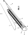
- FIGS. 2 and 3 illustrate the tool assembly 104 of the loading unit 100 of the surgical stapling device 10.
- the tool assembly 104 is pivotally secured to a body portion 102 ( FIG. 1 ) of the loading unit 100 and includes a jaw assembly 106 having an anvil assembly 114 and a cartridge assembly 116.
- the cartridge assembly 116 includes a channel member 118, and a staple cartridge 116a that is received within the channel member 118.
- the anvil assembly 114 and cartridge assembly 116 are pivotable relative to each other between an open position ( FIG. 10 ) and an approximated or clamped position ( FIG. 12 ).
- a drive assembly 120 ( FIG. 4 ) extends from the body portion 102 of the loading unit 100 into the tool assembly 104 and is translatable through the tool assembly 104 to cause actuation of the jaw assembly 106 to fire staples "S" from the staple cartridge 116a.
- the loading unit 100 is substantially as described in U.S. Pat. No. 9,016,539 ("the '539 patent"). Accordingly, the components of the loading unit 100 which are common to that which is disclosed in the '539 patent will only be described herein to the extent necessary to fully disclose the aspects of the drive assembly 120 and its method of operation.
- the anvil assembly 114 of the jaw assembly 106 of the tool assembly 104 defines a channel 151 ( FIG. 10 ) and includes an inner clamping surface 114a.
- the anvil assembly 114 includes an anvil body 150 and an anvil plate 152 ( FIG. 10 ) secured to the underside of the anvil body 150 to form the channel 151.
- the anvil plate 152 defines plurality of staple receiving depressions (not shown).
- the staple cartridge 116a of the jaw assembly 106 includes a cartridge body 156 supported in a cartridge holder 158, a plurality of staples "S", and a staple firing assembly 160.
- the staple firing assembly 160 includes an actuation sled 162 ( FIG. 3 ) and a plurality of pusher members 164 ( FIG. 3 ).
- the channel member 118 defines a cavity 119 ( FIG. 3 ) that receives the staple cartridge 116a. More specifically, the cartridge body 156 of the staple cartridge 116a is secured within the cavity 119 of the channel member 118 with, e.g., a snap-fit connection. Other forms of connections are contemplated and may be used in place of the snap-fit connection, or in addition thereto, to fixedly or releasably secure the cartridge assembly 116 within the cavity 119 of the channel member 118.
- the channel member 118 is pivotally secured to the anvil assembly 114, and includes an inner clamping surface 118a ( FIG. 10 ) defining a channel or slot 161.
- the cartridge body 156 defines a plurality of laterally spaced staple retention slots 153 which are positioned in alignment with the staple receiving depressions (not shown) in the anvil plate 152 ( FIG. 10 ) of the anvil assembly 114 when the jaw assembly 106 is in the clamped position.
- Each retention slot 153 is configured to receive a fastener or staple "S" and a pusher 164.
- the actuation sled 162 is positioned within the cartridge body 156 of the cartridge assembly 116 and is configured to pass longitudinally through the cartridge body 156 into engagement with the pushers 164 to lift the pushers within the cartridge body 156 and sequentially eject the staples "S" from the cartridge body 156.
- the actuation sled 162 supports a knife mechanism 166 that includes a knife that is cammed into a cutting position when the actuation sled 162 is engaged by the dynamic clamping member 122.
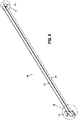
- FIGS. 4-7 illustrate the drive assembly 120 of the stapling device 10 ( FIG. 1 ) which includes a dynamic clamping member 122, a drive beam 124, an adjustment beam 126, and a securement mechanism 128.
- the drive beam 124 defines a longitudinal axis and extends proximally from the dynamic clamping member 122 into the body portion 102 of the loading unit 100.
- the adjustment beam 126 extends along a length of the drive beam 124 and is selectively securable to the drive beam 124 by the securement mechanism 128.
- a proximal end of the drive beam 124 is configured to engage a drive member (not shown) of the adapter assembly 30 and/or the powered handle assembly 20 for advancing and retracting the drive assembly 120 within the adapter assembly 30 and the tool assembly 104.
- a tab 130 ( FIG. 5 ) is disposed along the length of the drive beam 124 and defines a first opening 131a, a second opening 131b, a third opening 131c (collectively, openings 131).
- each of the openings 131 are oblong in a direction transverse to the longitudinal axis of the drive beam 124 to accommodate transverse movement of the adjustment beam 126 relative to the drive beam 124 as the adjustment beam 126 is moved longitudinally relative to the drive beam 124.
- the drive beam 124 may include only two openings or may include more than three openings.
- the tab 130 is shown formed on the drive beam 124, it is envisioned that the tab 130 may instead be formed on the adjustment beam 126.
- the adjustment beam 126 and the securement mechanism 128 operate as a mechanism for adjusting a clamping height "CH" ( FIG. 6 ) of the dynamic clamping member 122.
- the drive beam 124 and/or the adjustment beam 126 of the drive assembly 120 is formed from a plurality of stacked sheets that are formed of a resilient or flexible material, e.g., stainless steel.
- the dynamic clamping member 122 of the drive assembly 120 includes an upper flange portion 132, a lower flange portion 134, and a vertical strut 136 interconnecting the upper flange portion 132 and the lower flange portion 134.
- the upper flange portion 132 is sized and dimensioned to be slidably received within the channel 151 ( FIG. 10 ) of the anvil assembly 114 and includes a clamping surface 132a ( FIG. 13 ) that engages the inner clamping surface 114a ( FIG. 13 ) of the anvil assembly 114 to cause pivoting of the cartridge assembly 116 relative to the anvil assembly 114 to move the jaw assembly 106 from the open position to the clamped position.
- the lower flange portion 134 is sized and dimensioned to be slidably received within the channel 161 ( FIG. 13 ) of the channel member 118 and includes inclined surfaces 134a facing the upper flange portion 132 of the dynamic clamping member 122.
- the adjustment beam 126 of the drive assembly 120 extends along a length of the drive beam 124.
- a proximal portion 126a of the adjustment beam 126 defines an opening 127 for receiving the securement mechanism 128.
- the securement mechanism 128 includes the adjustment knob 128a and a threaded screw 128b, and the opening 127 is configured to securely receive the threaded screw 128b.
- the adjustment beam 126 may be secured relative to the drive beam 124 in any suitable manner.
- the opening 127 in the adjustment beam 126 is positioned to align with any one of the openings 131 in the tab 130 of the drive beam 124.
- An engagement portion 140 is formed on a distal end 126b of the adjustment beam 126 of the drive assembly 120.
- the engagement portion 140 of the adjustment beam 126 includes a pair of extensions 142 that are spaced apart from one another to form a slot 141 for receiving the vertical strut 136 of the dynamic clamping member 122.
- Each of the extensions 142 includes an adjustment flange 144 that is configured to be received within the channel 161 ( FIG. 10 ) of the channel member 118 and includes a clamping surface 144a and an opposed inclined surface 144b.
- the clamping surfaces 144a of the adjustment flanges 144 are configured to engage the inner clamping surface 118a ( FIG. 10 ) of the channel member 118.
- the engagement portion 140 of the adjustment beam 126 is configured such that when the vertical strut 136 of the dynamic clamping member 122 is received within the slot 141 of the engagement portion 140, the inclined surfaces 144b of the adjustment flanges 144 of the engagement portion 140 of the adjustment beam 126 engage the inclined surfaces 134a of the lower flange portion 134 of the dynamic clamping member 122.
- the distance between the clamping surface 132a of the of upper flange portion 132 of the dynamic clamping member 122 and the clamping surface 144a of the adjustment flange 144 of the engagement portion 140 of the adjustment beam 126 defines the clamping height "CH" ( FIG. 6 ).
- the clamping height "CH" may be adjusted.
- FIGS. 9-13 illustrate the drive assembly 120 of loading unit 100 of the stapling device 10 ( FIG. 1 ) in a first configuration.
- the adjustment beam 126 is longitudinally positioned relative to the drive beam 124 in its distal-most position such that the opening 127 in the adjustment beam 126 is aligned with the first opening 131a in the drive beam 124.
- the adjustment flanges 144 of the engagement portion 140 of the adjustment beam 126 are positioned relative to the lower flanges 134 of the dynamic clamping member 122 such that a first clamp height "H", i.e., the distance between the clamping surfaces 132a of the upper flange portion 132 of the dynamic clamping member 122 and the clamping surfaces 144a of the adjustment flanges 144, is greatest.
- H first clamp height
- the anvil assembly 114 pivots relative to the cartridge assembly 116 to create a gap height "GH" between a tissue contacting surface 114b of the anvil assembly 114 and a tissue contacting surface 116b of the cartridge assembly 116 of the jaw assembly 106.
- FIG. 9 illustrates the securement mechanism 128 of the drive assembly 120 in the first position.
- the adapter assembly 30 defines a slot 31 along its length for accommodating movement of the securement mechanism 128 of the drive assembly 120 during operation of the stapling device 10.
- the adapter assembly 30 includes markings 32 along the slot 31 to indicate the position the adjustment beam 126 relative to the drive beam 124 of the drive assembly 120.
- the securement mechanism 128 aligns with the distal-most marking of the markings 32 indicating that the stapling device 10 is configured to accommodate thick tissue.
- FIG. 10 illustrates the jaw assembly 106 of the tool assembly 104 of the loading unit 100 of the stapling device 10 ( FIG. 1 ) with the drive assembly 120 in the first configuration and in a retracted position.
- the drive assembly 120 is in the retracted position, the anvil assembly 114 is spaced from the cartridge assembly 116, i.e., in the open position, to permit placement of tissue between the tissue contacting surfaces 114b, 116b of the respective anvil assembly 114 and cartridge assembly 116.
- FIG. 11 illustrates the drive assembly 120 of the loading unit 100 in the first configuration with the adjustment beam 126 of the drive assembly 120 in its distal-most position relative to the drive beam 124 with the opening 127 in the adjustment beam 126 in alignment with the first opening 131a in the drive member 122.
- the distance between the clamping surface 132a of the upper flange portion 132 of the dynamic clamping member 122 and the clamping surface 144a of the adjustment flanges 144 of the engagement portion 140 of the adjustment beam 126 are spaced to define a first clamping height "CH1".
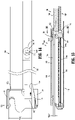
- FIGS. 12 and 13 illustrate the jaw assembly 106 of the tool assembly 104 of the stapling device 10 with the drive assembly 120 in the first configuration and in a partially advanced position, i.e., a pre-fired position in which the jaw assembly 106 is in the clamped position.
- a partially advanced position i.e., a pre-fired position in which the jaw assembly 106 is in the clamped position.
- the tissue contacting surfaces 114b, 116b of the anvil assembly 114 and the cartridge assembly 116, respectively, are spaced to define a first gap height "GH1".
- FIG. 14 illustrates the drive assembly 120 of the loading unit 100 in the second configuration. More particularly, the adjustment beam 126 of the drive assembly 120 is in its proximal-most position relative to the drive beam 124 of the drive assembly 120, with the opening 127 in the adjustment beam 126 in alignment with the third opening 131c in the drive member 122.
- the clamping surface 132a of the upper flange portion 132 of the dynamic clamping member 122 and the clamping surface 144a of the adjustment flanges 144 of the engagement portion 140 of the adjustment beam 126 are spaced to define a second clamp height "CH2" that is less than the first clamp height "CH1".
- the stapling device 10 is configured to accommodate thinner tissue than when the drive assembly 120 is in the first configuration.
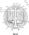
- FIGS. 15 and 16 illustrate the jaw assembly 106 of the tool assembly 104 of the stapling device 10 ( FIG. 1 ) with the drive assembly 120 in the second configuration, and in the partially advanced position.
- the partially advanced position receipt of the upper flange portion 132 of the dynamic clamping member 122 in the channel 151 of the anvil assembly 114 and engagement of the clamping surfaces 132a of the upper flange portion 132 with the inner clamping surface 114a of the anvil assembly 114 causes the anvil assembly 114 to pivot relative to the cartridge assembly 116 to the clamped position.
- the tissue contacting surfaces 114b, 116b of the anvil assembly 114 and the cartridge assembly 116, respectively, are spaced to define a second gap height "GH2".
- clamp height "CH” is shown and described as having a fixed distance once the adjustment beam 126 is secured relative to the drive beam 124, it is envisioned that the adjustment beam 126 may be moved relative to the drive beam 124 during the stapling procedure, i.e., as the drive assembly 120 is advanced through the jaw assembly 106, to adjusted the clamping height "CH” as the drive assembly 120 is advanced.
- the adjustment of the clamping height "CH” may be manual or automatic.
- the sensors will sense the tissue thickness and change the tissue gap as the stapler is fired, and in non-smart staplers, a biasing member maintains a specific pressure on the tissue independent of the tissue gap height.
- adjustment mechanism shown and described above relates to powered surgical staplers
- the aspects of the disclosure may be modified for use on manually actuated stapling devices.
- FIG. 17 illustrates a manual surgical stapling device according to exemplary aspects of the disclosure, shown generally as stapling device 10'.
- the stapling device 10' includes a manual handle assembly 20' including an adapter assembly 30', and a loading unit 100' that is releasably secured to the adapter assembly 30'.
- FIGS. 18 and 19 illustrate a drive assembly according to other aspects of the disclosure shown generally as drive assembly 220.
- the drive assembly 220 is similar to the drive assembly 120 described hereinabove and will only be described in detail as relates to the differences therebetween.
- the drive assembly 220 includes a dynamic clamping assembly 222, a drive beam 224, and an adjustment beam 226 ( FIG. 19 ) slidably disposed relative to the drive beam 222 within a slot 223 formed in the drive beam 222.
- the dynamic clamping assembly 222 includes a clamping member 223, and a lower flange member 234.
- the clamping member 223 includes an upper flange member 232 and a vertical strut 236.
- the lower flange member 234 is secured to the vertical strut 236 of the clamping member 223 by a dovetail connection 235 ( FIG. 18 ), or in any other suitable manner.
- the adjustment beam 226 is secured to the lower flange member 234 in any suitable manner and operates to move the lower flange member 234 along a longitudinal axis of the drive assembly 220 relative to the vertical strut 236.
- the lower flange member 234 and the vertical strut 236 include abutting inclined surfaces 234b, 236a. Longitudinal movement of the lower flange member 234 relative to the vertical strut 236 varies the distance between a clamping surface 232a ( FIG. 18 ) of the upper flange portion 232 of the clamping member 223 and a clamping surface 234a ( FIG. 18 ) of the lower flange member 234, e.g., a clamping height "CH".
- the drive assembly 220 is in a first configuration, with the adjustment beam 226 in a distal-most position relative to the drive beam 224.
- the clamping height "C" is a first distance.
- longitudinal movement of the adjustment beam 226 relative to the drive beam 224 as indicated by arrows "A"
- moves the inclined surface 234b of the lower flange member 234 relative the inclined surface 236a of the vertical strut such that the lower flange member 234 moves towards the upper flange portion 232, as indicated by arrow "B”
- to adjust the clamping height "CH” FIG. 19
- FIGS. 20 and 21 illustrate a dynamic clamping assembly according to another aspect of the disclosure shown generally as dynamic clamping assembly 320.
- the dynamic clamping assembly 320 is similar to the dynamic clamping assembly 222 described hereinabove and will only be described in detail as relates to the differences therebetween.
- the dynamic clamping assembly 322 includes a clamping member 323 and a lower flange member 334.
- the clamping member 323 includes an upper flange portion 332 and a vertical strut 336.
- the lower flange member 334 is supported within a slot 325 of in the vertical strut 336. More particularly, the lower flange member 334 is movable vertically within the slot 325 perpendicular to a longitudinal axis of the dynamic clamping assembly 322, as indicated by arrow "C" in FIG. 21 .
- a distance between a clamping surface 332a of the upper flange portion 332 and a clamping surface 334a of the lower flange member 334 may be adjusted by raising or lowering the lower flange member 334 relative to the vertical strut 336.
- An adjustment member 326 extends through a cylindrical passage 327 in the vertical strut 336 and through the lower flange member 334.
- the adjustment member 326 is biased distally by a spring member 328 ( FIG. 21 ).
- the adjustment member 326 includes an inclined surface 326a that is configured to engage the lower flange member 334 to change the relative position of the upper flange portion 332 and the lower flange member 334, respectively, in response to a change in the longitudinal position of the adjustment member 326 relative to the clamping member 323.
- a plug member 324 secures the spring member 328 within the cylindrical passage 237. Longitudinal movement of the plug member 324 relative to the vertical strut 336 increase and decrease the compressive force on the spring member 328. By reducing the biasing force provided by the spring member 328 to the adjustment member 326, the adjustment member 326 is able to move relative to the lower flange member 334.
- the bias on the spring member 328 may be effected by a threaded rod (not shown) extending through the loading unit, e.g., loading unit 100 ( FIG. 1 ).
- Rotation of the threaded rod in a first direction would cause retraction of the plug 234 and thus, decompression of the spring member 328, thereby permitting proximal movement of the adjustment member 326.
- rotation of the threaded rod in a second direction would cause advancement of the plug 328, and thus, compress the spring member 328 thereby causing distal movement of the adjustment member 326.
- the dynamic clamping assembly 322 defines a first clamping height "CH1".Retraction of the adjustment member 326, as indicated by arrow “E” in FIG. 21 , to its proximal-most position, causes the lower flange member 334 to move away from upper flange portion 332, as indicated by arrow “F” in FIG. 21 ".
- the dynamic clamping assembly 322 defines a second clamping height "CH2". The second clamping height "CH2" is greater than the first clamping height "CH1".
- the adjustment member 326 By positioning the adjustment member 326 with the inclined surface 326a aligned with the lower flange member 334, i.e., between its proximal-most and distal-most positions, the adjustment member 326 may be positioned to create a clamping height "CH” between the first and second clamping heights "CH1" and "CH2".
- FIGS. 22 and 23 illustrate a drive assembly according to another aspect of the disclosure shown generally as drive assembly 420.
- the drive assembly 420 includes a dynamic clamping assembly 422 substantially similar to the dynamic clamping assembly 322 described hereinabove and will only be described in detail as relates to the differences therebetween.
- the dynamic clamping assembly 422 includes a clamping member 423 and a lower flange member 434.
- the clamping member 423 includes an upper flange portion 432 and a vertical strut 436.
- the lower flange member 434 is supported within a slot 425 of the vertical strut 436 and is movable vertically within the slot 425 perpendicular to a longitudinal axis of the dynamic clamping assembly 422, as indicated by arrow "G" in FIG. 22 .
- a clamping height "CH” defined between a clamping surface 432a ( FIG. 22 ) of the upper flange portion 432 and a clamping surface 434a of the lower flange member 434 may be adjusted by raising or lowering the lower flange member 434 relative to the vertical strut 436.
- An adjustment member 426 extends through a cylindrical passage 427 ( FIG. 22 ) in the vertical strut 436 and through the lower flange member 434.
- An adjustment beam 428a is secured to and extends from the adjustment member 426.
- the adjustment beam 428a extends along an axis that is parallel to a drive beam 428 that extends from the clamping member 423.
- the adjustment member 426 is movable between an advanced position ( FIG. 22 ) and a retracted position by moving the adjustment beam 428a relative to the drive beam 428.
- the adjustment member 426 includes an inclined surface 426a that is positioned to engage the lower flange member 434 depending on the longitudinal position of the adjustment member 426 relative to the clamping member 423.
- the clamping height "CH” is a first distance
- the clamping height "CH” is a second distance. The second distance is greater than the first distance.
- FIGS. 24 and 25 illustrate a dynamic clamping assembly according to another aspect of the disclosure shown generally as dynamic clamping assembly 522.
- the dynamic clamping assembly 522 is similar to the dynamic clamping assembly 322 described hereinabove and will only be described in detail as relates to the differences therebetween.
- the dynamic clamping assembly 522 includes a clamping member 523 and a lower flange member 534.
- the clamping member 523 includes an upper flange portion 532 and a vertical strut 536.
- the lower flange member 534 is supported within a slot 525 of the vertical strut 536 and is movable vertically within the slot 525 perpendicular to a longitudinal axis of the dynamic clamping assembly 522.
- a clamping height "CH" defined between a clamping surface 532a ( FIG. 24 ) of the upper flange portion 532 and a clamping surface 534a of the lower flange member 534 may be adjusted by raising or lowering the lower flange member 534 relative to the vertical strut 536.
- An adjustment member 526 extends through a cylindrical passage 527 in the vertical strut 536 and through the lower flange member 534.
- the adjustment member 526 includes an inclined surface 526a configured to engage the lower flange member 534 depending on the longitudinal position of the adjustment member 526 relative to the clamping member 523.
- the adjustment member 526 is moveable along a longitudinal axis of the dynamic clamping assembly 522 by a threaded adjustment shaft 528. By rotating the adjustment shaft 528, the adjustment member 526 moves relative to the lower flange member 534.
- a clamping height "CH” is a first distance
- the clamping height "CH” is a second distance. The second distance is greater than the first distance.
- FIGS. 26 and 27 illustrate a dynamic clamping assembly according to another aspect of the disclosure shown generally as dynamic clamping assembly 622.
- the dynamic clamping assembly 622 is similar to the dynamic clamping assemblies 322, 522 described hereinabove and will only be described in detail as relates to the differences therebetween.
- the dynamic clamping assembly 622 includes a clamping member 623 and a lower flange member 634.
- the clamping member 623 includes an upper flange portion 632 and a vertical strut 636.
- the lower flange member 634 is supported within a slot 625 of the vertical strut 636 and is movable vertically within the slot 625 perpendicular to a longitudinal axis of the dynamic clamping assembly 622.
- a clamping height "CH" defined between a clamping surface 632a ( FIG. 26 ) of the upper flange portion 632 and a clamping surface 634a ( FIG. 26 ) of the lower flange member 634 may be adjusted by raising or lowering the lower flange member 634 relative to the vertical strut 636.
- An adjustment member 626 extends through a cylindrical passage 627 in the vertical strut 636 and through the lower flange member 634.
- the adjustment member 626 includes a conical distal portion 626a that is configured to engage an inclined surface 634b of the lower flange member 634.
- the clamping height "CH" may be adjusted.
- the adjustment member 626 is moveable along a longitudinal axis of the dynamic clamping assembly 622 by a threaded engagement with the vertical strut 636 of the clamping member 623. By rotating the adjustment member 626, the adjustment member 626 move relatives to the lower flange member 634.
- the clamping height "CH” is a first distance
- the clamping height "CH” is a second distance. The second distance is greater than the first distance.
- the adjustment member 626 may operate as a drive member for advancing the dynamic clamping assembly 622 through a jaw assembly, for example, jaw assembly 106 ( FIG. 1 ).
- the dynamic clamping assembly 622 may be advanced by a drive member (not shown).
- FIGS. 28 and 29 illustrate a dynamic clamping assembly according to another aspect of the disclosure shown generally as dynamic clamping assembly 722.
- the dynamic clamping assembly 722 is similar to the dynamic clamping assemblies 322, 522, 622 described hereinabove and will only be described in detail as relates to the differences therebetween.
- the dynamic clamping assembly 722 includes a clamping member 723 and a lower flange member 734.
- the clamping member 723 includes an upper flange portion 732 and a vertical strut 736.
- the lower flange member 734 is supported within a slot 725 of the vertical strut 736 and is movable vertically within the slot 725, i.e., perpendicular to a longitudinal axis of the dynamic clamping assembly 722.
- a clamping height "CH" defined between a clamping surface 732a ( FIG. 28 ) of the upper flange portion 732 and a clamping surface 734a ( FIG. 28 ) of the lower flange member 734 may be adjusted by raising or lowering the lower flange member 734 relative to the vertical strut 736.
- An adjustment member 726 extends through and from a cylindrical passage 727 in the vertical strut 736 and through the lower flange member 734.
- the adjustment member 726 includes a conical portion 726a that is configured to engage an inclined surface 734b of the lower flange member 734.
- the clamping height "CH" may be adjusted.
- the adjustment member 726 may be moveable along a longitudinal axis of the dynamic clamping assembly 722 by a threaded engagement (not shown) with the vertical strut 736 of the clamping member 723.
- a clamping height "CH” is a first distance, and when the adjustment member 726 is in its distal-most position ( FIG. 29 , shown in phantom) relative to the clamping member 723, the clamping height "CH” is a second distance. The second distance is greater than the first distance.
- FIGS. 30 and 31 illustrate a dynamic clamping assembly according to another aspect of the disclosure shown generally as dynamic clamping assembly 822.
- the dynamic clamping assembly 822 is similar to the dynamic clamping assemblies described hereinabove and will only be described in detail as relates to the differences therebetween.
- the dynamic clamping assembly 822 includes a clamping member 823 and a lower flange member 834.
- the clamping member 823 includes an upper flange portion 832 and a vertical strut 836.
- the lower flange member 834 is supported within a slot 825 of the vertical strut 836. More particularly, the lower flange member 834 is movable vertically within the slot 825, i.e., perpendicular to a longitudinal axis of the dynamic clamping assembly 822. In this manner, a clamping height "CH" defined between a clamping surface 832a ( FIG. 30 ) of the upper flange portion 832 and a clamping surface 834a ( FIG. 30 ) of the lower flange member 834 may be adjusted by raising or lowering the lower flange member 834 relative to the vertical strut 836.
- CH clamping height
- An adjustment member 826 extends through and from a cylindrical passage 827 in the vertical strut 836 and through the lower flange member 834.
- the adjustment member 826 includes an inclined surface 826a that is configured to engage an inclined surface 834b of the lower flange member 834.
- the adjustment member 826 is moveable along a longitudinal axis of the dynamic clamping assembly 822 to adjust a clamping height "CH" of the dynamic clamping assembly 822.
- the clamping height "CH” is a first distance
- the clamping height "CH” is a second distance. The second distance is greater than the first distance.
- FIGS. 32-35 illustrate a drive assembly according to another aspect of the disclosure shown generally as drive assembly 920.
- the drive assembly 920 is substantially similar to the drive assemblies described hereinabove and will only be described in detail as relates to the differences therebetween.
- the drive assembly 920 includes a dynamic clamping assembly 922 having a clamping member 923 and a lower flange member 934.
- the clamping member 923 includes an upper flange portion 932 and a vertical strut 936.
- the lower flange member 934 is received about and supported by the vertical strut 936 and is movable vertically relative to the vertical strut 936, i.e., perpendicular to a longitudinal axis of the clamping member 922.
- a clamping height "CH" defined between a clamping surface 932a ( FIG. 30 ) of the upper flange portion 932 and a clamping surface 834a ( FIG. 30 ) of the lower flange member 934 may be adjusted by raising or lowering the lower flange member 934 relative to the vertical strut 936.
- An adjustment member 926 is supported within a cylindrical recess 925 defined by the vertical strut 936 and the lower flange member 934.
- the adjustment member 926 includes a cam member 926a.
- the clamping height "CH” may be adjusted.
- the adjustment member 926 is rotatable about its central axis to adjust a clamping height "CH" of the dynamic clamping assembly 922.
- the clamping height "CH” is a first distance
- the clamping height "CH” is a second distance. The second distance is greater than the first distance.
- the orientation of the cam member 926a may be adjusted by moving an adjustment beam 928a of the drive assembly 920 relative to a drive beam 928 of the drive assembly 920.
- This may include a slotted, geared, or ratcheted arrangement, or other suitable configuration.
Landscapes
- Health & Medical Sciences (AREA)
- Life Sciences & Earth Sciences (AREA)
- Surgery (AREA)
- Heart & Thoracic Surgery (AREA)
- Engineering & Computer Science (AREA)
- Biomedical Technology (AREA)
- Nuclear Medicine, Radiotherapy & Molecular Imaging (AREA)
- Medical Informatics (AREA)
- Molecular Biology (AREA)
- Animal Behavior & Ethology (AREA)
- General Health & Medical Sciences (AREA)
- Public Health (AREA)
- Veterinary Medicine (AREA)
- Surgical Instruments (AREA)
Abstract
Description
- This disclosure relates to surgical stapling devices having a clamping member for setting a tissue gap. More particularly, this disclosure relates to surgical stapling devices having a clamping member with an adjustable height for adjusting a tissue gap.
- Surgical stapling devices for stapling tissue are well known in the art and typically include a handle assembly, a body portion extending distally from the handle assembly, and a tool assembly supported on a distal end of the body portion. The tool assembly includes first and second jaws which are movable in relation to each other between open and closed or approximated positions. The first jaw includes an anvil assembly and the second jaw supports a cartridge which houses a plurality of staples. The cartridge can also include a knife for severing tissue. In known devices, the stapling apparatus includes a clamping member that is engaged with the first and second jaws and is movable along the first and second jaws to set a tissue gap between the anvil assembly and the cartridge during a stapling procedure. However, the size of the tissue gap appropriate for a surgical procedure depends on the thickness of the tissue being treated which will change from procedure to procedure, and may change along the length of the first and second jaws.
- A continuing need exists in the art for a surgical stapling device capable of changing the size of the tissue gap set by the clamping member to accommodate tissues of varying thickness.
- A surgical stapling device includes a body portion, a tool assembly, and a drive assembly. The body portion defines a longitudinal axis and has a proximal portion and a distal portion. The tool assembly is supported on the distal portion of the body portion. The tool assembly includes an anvil assembly, a channel member pivotally supported relative to the anvil assembly, and a staple cartridge releasably disposed within the channel member. The tool assembly is movable from an open position to an approximated position. The staple cartridge supports a plurality of staples and includes an actuation sled that is movable between a retracted position and an advanced position to eject the plurality of staples from the staple cartridge. The drive assembly is movably supported within the tool assembly from a retracted position to an advanced position to move the tool assembly from the open position to the approximated position and to maintain the tool assembly in the approximated position. The drive assembly includes a clamping member and an adjustment member. The clamping member includes a first clamping surface configured to engage the anvil assembly. The adjustment member includes a second clamping surface configured to engage the staple cartridge. The first clamping surface is spaced from the second clamping surface to define a clamping height. The adjustment member is moveable relative to the clamping member between a first position and a second position to change the clamping height.
- In certain aspects of the disclosure, the first position of the adjustment member is longitudinally spaced from the second position of the adjustment member. The first position of the adjustment member may be vertically spaced from the second position of the adjustment member. The channel member may define a slot and the adjustment member may include a flange. The flange may be receivable within the slot of the channel member. The anvil assembly may define a slot and the clamping member may include a pair of flanges. The pair of flanges of the clamping member may be receivable within the slot of the anvil assembly.
- In some aspects of the disclosure, the drive assembly includes a drive beam and a securement mechanism for securing the adjustment member relative to the drive beam. The securement member may include an adjustment knob and a thread screw extending from the adjustment knob. Movement of the drive assembly beyond the partially advanced position may move the actuation sled from a retracted position to an advanced position to eject the plurality of staples from the staple cartridge. The clamping member may include an upper flange and a lower flange interconnected by a vertical strut. The clamping member may be positioned to engage the actuation sled to move the actuation sled distally within the staple cartridge as the drive assembly moves from the retracted position towards a fully advanced position. The adjustment member may include an inclined surface and the clamping member may include an inclined surface. Movement of the adjustment member relative to the clamping member may slide the inclined surfaces relative to each other.
- A drive assembly for a surgical stapling assembly includes a clamping member, a drive beam extending from the clamping member, and an adjustment member. The clamping member includes an upper flange portion and a vertical strut. The upper flange includes a first clamping surface configured to engage an anvil assembly. The drive beam extends from the clamping member and is configured for operable engagement with an actuation mechanism. The adjustment member is disposed relative to the clamping member and includes a second clamping surface configured to engage a staple cartridge. The first clamping surface is spaced from the second clamping surface to define a clamping height. The adjustment member is moveable relative to the clamping member between a first position and a second position to change the clamping height.
- In certain aspects of the disclosure, the upper flange portion is configured to be received within a slot of the anvil assembly. The adjustment member may include a flange portion configured to be received within a slot of a staple cartridge. The drive assembly may further include a securement mechanism for securing the drive beam relative to the adjustment mechanism. The securement mechanism may be a threaded screw. The first position of the adjustment member may be longitudinally spaced from the second position of the adjustment member. The first position of the adjustment member may be vertically spaced from the second position of the adjustment member.
- Various aspects of the disclosure are described herein with reference to the drawings, wherein:
-
FIG. 1 is a side, perspective view of a powered surgical stapling device including a loading unit having a tool assembly in an open position according to aspects of the disclosure; -
FIG. 2 is a side, perspective view of the indicated area of detail shown inFIG. 1 ; -
FIG. 3 is side perspective view with parts separated of the loading unit shown inFIGS. 1 and2 ; -
FIG. 4 is a side perspective view a drive assembly of the surgical stapling device shown inFIG. 1 ; -
FIG. 5 is an enlarged, side perspective view with parts separated of the drive assembly shown inFIG. 4 ; -
FIG. 6 is an enlarged, side perspective view of the indicated area of detail shown inFIG. 4 ; -
FIG. 7 is an enlarged, side perspective view of the indicated area of detail shown inFIG. 4 ; -
FIG. 8 is a cross-sectional view taken along section line 8-8 shown inFIG. 7 ; -
FIG. 9 is a side, perspective view of the indicated area of detail shown inFIG. 1 ; -
FIG. 10 is an enlarged, side, cross-sectional view of the tool assembly shown inFIG. 2 in the open position with the drive assembly in a first configuration and in a retracted position; -
FIG. 11 is a side perspective view of the drive assembly shown inFIG. 4 in the first configuration; -
FIG. 12 is a side perspective view of the tool assembly shown inFIG. 10 in a closed position with the drive assembly in the first configuration and in a partially advanced position; -
FIG. 13 is a cross-sectional view taken along section line 13-13 shown inFIG. 12 ; -
FIG. 14 is a side view of the drive assembly in a second configuration; -
FIG. 15 is a side, cross-sectional view of the tool assembly shown inFIG. 10 in a closed position with the drive assembly in the second configuration and in a partially advanced position; -
FIG. 16 is a cross-sectional view taken along section line 16-16 shown inFIG. 15 ; -
FIG. 17 is a side, perspective view of a manual surgical stapling device including a loading unit having a tool assembly in an open position according to other aspects of the disclosure; -
FIG. 18 is an enlarged, side perspective view of an alternate version of the drive assembly shown inFIG. 4 ; -
FIG. 19 is a side, cross-sectional view taken along section line 19-19 shown inFIG. 18 ; -
FIG. 20 is a side, perspective view of various aspects of another alternate version of the drive assembly shown inFIG. 4 ; -
FIG. 21 is a cross-sectional view taken along section line 21-21 shown inFIG. 20 ; -
FIG. 22 is a side perspective view of yet another alternate version of the drive assembly; -
FIG. 23 is a side cross-sectional view taken along section line 23-23shown inFIG. 22 ; -
FIG. 24 is a side, perspective view of a dynamic clamping member of still another alternative version of the drive assembly; -
FIG. 25 is a side, cross-sectional view taken along section line 25-25 shown inFIG. 24 ; -
FIG. 26 is a side, perspective view of a dynamic clamping member of still yet another alternative version of the drive assembly; -
FIG. 27 is a side, cross-sectional view taken along section line 27-27 shown inFIG. 26 ; -
FIG. 28 is a side, perspective view of a dynamic clamping member of another alternate version of the drive assembly; -
FIG. 29 is a side, cross-sectional view taken along section line 29-29 shown inFIG. 28 ; -
FIG. 30 is a side, perspective view of a dynamic clamping member and an adjustment beam of still another alternative version of the drive assembly; -
FIG. 31 is a side, cross-sectional view of the dynamic clamping member and the adjustment beam shown inFIG. 30 ; -
FIG. 32 is a side perspective view of still yet another alternate version of the drive assembly; -
FIG. 33 is a top, perspective view of a cam member of the drive assembly shown inFIG. 32 ; -
FIG. 34 is a side cross-sectional view taken along section line 34-34 shown inFIG. 32 ; and -
FIG. 35 is an end, cross-sectional view taken along section line 35-35 shown inFIG. 34 . - The disclosed surgical stapling device will now be described in detail with reference to the drawings in which like reference numerals designate identical or corresponding elements in each of the several views. However, it is to be understood that the disclosed aspects of the disclosure are merely exemplary of the disclosure and may be embodied in various forms. Well-known functions or constructions are not described in detail to avoid obscuring the disclosure in unnecessary detail. Therefore, specific structural and functional details disclosed herein are not to be interpreted as limiting, but merely as a basis for the claims and as a representative basis for teaching one skilled in the art to variously employ the disclosure in virtually any appropriately detailed structure. In addition, directional terms such as front, rear, upper, lower, top, bottom, distal, proximal, and similar terms are used to assist in understanding the description and are not intended to limit the disclosure.
- In this description, the term "proximal" is used generally to refer to that portion of the device that is closer to a clinician, while the term "distal" is used generally to refer to that portion of the device that is farther from the clinician. In addition, the term "clinician" is used generally to refer to medical personnel including doctors, nurses, and support personnel.
- The disclosed surgical stapling device includes a drive assembly having a dynamic clamping member that is configured with an adjustable clamp height for adjusting a maximum tissue gap between tissue contact surfaces of anvil and cartridge assemblies of the stapling device.
-
FIG. 1 illustrates a surgical stapling device according to exemplary aspects of the disclosure, shown generally as staplingdevice 10. The staplingdevice 10 includes apowered handle assembly 20, anadapter assembly 30 releasably secured to thepowered handle assembly 20, and aloading unit 100 releasably secured to theadapter assembly 30. Although shown as individual or separable components, it is envisioned that any or all thepowered handle assembly 20,adapter assembly 30, andloading unit 100 may be integrally formed. - As will be described in further detail below, the
surgical stapling device 10 includes anadjustment mechanism 128 that is engaged with a drive assembly 120 (FIG. 4 ) of thesurgical stapling device 10. As shown, theadjustment mechanism 128 may include anadjustment knob 128a that is supported on theadapter assembly 30, theloading unit 100, or thepowered handle assembly 20. -
FIGS. 2 and3 illustrate thetool assembly 104 of theloading unit 100 of thesurgical stapling device 10. Thetool assembly 104 is pivotally secured to a body portion 102 (FIG. 1 ) of theloading unit 100 and includes ajaw assembly 106 having ananvil assembly 114 and acartridge assembly 116. Thecartridge assembly 116 includes achannel member 118, and astaple cartridge 116a that is received within thechannel member 118. Theanvil assembly 114 andcartridge assembly 116 are pivotable relative to each other between an open position (FIG. 10 ) and an approximated or clamped position (FIG. 12 ). A drive assembly 120 (FIG. 4 ) extends from thebody portion 102 of theloading unit 100 into thetool assembly 104 and is translatable through thetool assembly 104 to cause actuation of thejaw assembly 106 to fire staples "S" from thestaple cartridge 116a. - The
loading unit 100 is substantially as described inU.S. Pat. No. 9,016,539 loading unit 100 which are common to that which is disclosed in the '539 patent will only be described herein to the extent necessary to fully disclose the aspects of thedrive assembly 120 and its method of operation. - The
anvil assembly 114 of thejaw assembly 106 of thetool assembly 104 defines a channel 151 (FIG. 10 ) and includes aninner clamping surface 114a. In certain aspects of the disclosure, theanvil assembly 114 includes an anvil body 150 and an anvil plate 152 (FIG. 10 ) secured to the underside of the anvil body 150 to form thechannel 151. Theanvil plate 152 defines plurality of staple receiving depressions (not shown). - The
staple cartridge 116a of thejaw assembly 106 includes acartridge body 156 supported in acartridge holder 158, a plurality of staples "S", and astaple firing assembly 160. Thestaple firing assembly 160 includes an actuation sled 162 (FIG. 3 ) and a plurality of pusher members 164 (FIG. 3 ). Thechannel member 118 defines a cavity 119 (FIG. 3 ) that receives thestaple cartridge 116a. More specifically, thecartridge body 156 of thestaple cartridge 116a is secured within thecavity 119 of thechannel member 118 with, e.g., a snap-fit connection. Other forms of connections are contemplated and may be used in place of the snap-fit connection, or in addition thereto, to fixedly or releasably secure thecartridge assembly 116 within thecavity 119 of thechannel member 118. - The
channel member 118 is pivotally secured to theanvil assembly 114, and includes aninner clamping surface 118a (FIG. 10 ) defining a channel orslot 161. Thecartridge body 156 defines a plurality of laterally spacedstaple retention slots 153 which are positioned in alignment with the staple receiving depressions (not shown) in the anvil plate 152 (FIG. 10 ) of theanvil assembly 114 when thejaw assembly 106 is in the clamped position. Eachretention slot 153 is configured to receive a fastener or staple "S" and apusher 164. Theactuation sled 162 is positioned within thecartridge body 156 of thecartridge assembly 116 and is configured to pass longitudinally through thecartridge body 156 into engagement with thepushers 164 to lift the pushers within thecartridge body 156 and sequentially eject the staples "S" from thecartridge body 156. Theactuation sled 162 supports a knife mechanism 166 that includes a knife that is cammed into a cutting position when theactuation sled 162 is engaged by thedynamic clamping member 122. -
FIGS. 4-7 illustrate thedrive assembly 120 of the stapling device 10 (FIG. 1 ) which includes adynamic clamping member 122, adrive beam 124, anadjustment beam 126, and asecurement mechanism 128. Thedrive beam 124 defines a longitudinal axis and extends proximally from thedynamic clamping member 122 into thebody portion 102 of theloading unit 100. Theadjustment beam 126 extends along a length of thedrive beam 124 and is selectively securable to thedrive beam 124 by thesecurement mechanism 128. A proximal end of thedrive beam 124 is configured to engage a drive member (not shown) of theadapter assembly 30 and/or thepowered handle assembly 20 for advancing and retracting thedrive assembly 120 within theadapter assembly 30 and thetool assembly 104. A tab 130 (FIG. 5 ) is disposed along the length of thedrive beam 124 and defines afirst opening 131a, asecond opening 131b, athird opening 131c (collectively, openings 131). In aspects of the disclosure, each of theopenings 131 are oblong in a direction transverse to the longitudinal axis of thedrive beam 124 to accommodate transverse movement of theadjustment beam 126 relative to thedrive beam 124 as theadjustment beam 126 is moved longitudinally relative to thedrive beam 124. Although shown to include threeopenings 131, it is envisioned that thedrive beam 124 may include only two openings or may include more than three openings. Although thetab 130 is shown formed on thedrive beam 124, it is envisioned that thetab 130 may instead be formed on theadjustment beam 126. As will be described in detail below, theadjustment beam 126 and thesecurement mechanism 128 operate as a mechanism for adjusting a clamping height "CH" (FIG. 6 ) of thedynamic clamping member 122. - In certain aspects of the disclosure, the
drive beam 124 and/or theadjustment beam 126 of thedrive assembly 120 is formed from a plurality of stacked sheets that are formed of a resilient or flexible material, e.g., stainless steel. - The
dynamic clamping member 122 of thedrive assembly 120 includes anupper flange portion 132, alower flange portion 134, and avertical strut 136 interconnecting theupper flange portion 132 and thelower flange portion 134. Theupper flange portion 132 is sized and dimensioned to be slidably received within the channel 151 (FIG. 10 ) of theanvil assembly 114 and includes aclamping surface 132a (FIG. 13 ) that engages theinner clamping surface 114a (FIG. 13 ) of theanvil assembly 114 to cause pivoting of thecartridge assembly 116 relative to theanvil assembly 114 to move thejaw assembly 106 from the open position to the clamped position. Thelower flange portion 134 is sized and dimensioned to be slidably received within the channel 161 (FIG. 13 ) of thechannel member 118 and includesinclined surfaces 134a facing theupper flange portion 132 of thedynamic clamping member 122. - The
adjustment beam 126 of thedrive assembly 120 extends along a length of thedrive beam 124. Aproximal portion 126a of theadjustment beam 126 defines anopening 127 for receiving thesecurement mechanism 128. As shown, thesecurement mechanism 128 includes theadjustment knob 128a and a threadedscrew 128b, and theopening 127 is configured to securely receive the threadedscrew 128b. Although shown as a threaded connection, it is envisioned that theadjustment beam 126 may be secured relative to thedrive beam 124 in any suitable manner. Theopening 127 in theadjustment beam 126 is positioned to align with any one of theopenings 131 in thetab 130 of thedrive beam 124. - An
engagement portion 140 is formed on adistal end 126b of theadjustment beam 126 of thedrive assembly 120. Theengagement portion 140 of theadjustment beam 126 includes a pair ofextensions 142 that are spaced apart from one another to form aslot 141 for receiving thevertical strut 136 of thedynamic clamping member 122. Each of theextensions 142 includes anadjustment flange 144 that is configured to be received within the channel 161 (FIG. 10 ) of thechannel member 118 and includes aclamping surface 144a and an opposedinclined surface 144b. The clamping surfaces 144a of theadjustment flanges 144 are configured to engage theinner clamping surface 118a (FIG. 10 ) of thechannel member 118. Theengagement portion 140 of theadjustment beam 126 is configured such that when thevertical strut 136 of thedynamic clamping member 122 is received within theslot 141 of theengagement portion 140, theinclined surfaces 144b of theadjustment flanges 144 of theengagement portion 140 of theadjustment beam 126 engage theinclined surfaces 134a of thelower flange portion 134 of thedynamic clamping member 122. The distance between the clampingsurface 132a of the ofupper flange portion 132 of thedynamic clamping member 122 and theclamping surface 144a of theadjustment flange 144 of theengagement portion 140 of theadjustment beam 126 defines the clamping height "CH" (FIG. 6 ). As will be described in further detail below, by changing the longitudinal position of theadjustment beam 126 of thedrive assembly 120 relative to thedrive beam 124 of thedrive assembly 120, the clamping height "CH" may be adjusted. -
FIGS. 9-13 illustrate thedrive assembly 120 ofloading unit 100 of the stapling device 10 (FIG. 1 ) in a first configuration. In the first configuration, theadjustment beam 126 is longitudinally positioned relative to thedrive beam 124 in its distal-most position such that theopening 127 in theadjustment beam 126 is aligned with thefirst opening 131a in thedrive beam 124. When theadjustment beam 126 is in the distal-most position, theadjustment flanges 144 of theengagement portion 140 of theadjustment beam 126 are positioned relative to thelower flanges 134 of thedynamic clamping member 122 such that a first clamp height "H", i.e., the distance between the clamping surfaces 132a of theupper flange portion 132 of thedynamic clamping member 122 and the clamping surfaces 144a of theadjustment flanges 144, is greatest. In this manner, when thedynamic clamping member 122 is advanced, theanvil assembly 114 pivots relative to thecartridge assembly 116 to create a gap height "GH" between atissue contacting surface 114b of theanvil assembly 114 and atissue contacting surface 116b of thecartridge assembly 116 of thejaw assembly 106. -
FIG. 9 illustrates thesecurement mechanism 128 of thedrive assembly 120 in the first position. As shown, theadapter assembly 30 defines aslot 31 along its length for accommodating movement of thesecurement mechanism 128 of thedrive assembly 120 during operation of the staplingdevice 10. Theadapter assembly 30 includesmarkings 32 along theslot 31 to indicate the position theadjustment beam 126 relative to thedrive beam 124 of thedrive assembly 120. Whendrive assembly 120 is in a first configuration with thesecurement mechanism 128 in the first position, thesecurement mechanism 128 aligns with the distal-most marking of themarkings 32 indicating that the staplingdevice 10 is configured to accommodate thick tissue. -
FIG. 10 illustrates thejaw assembly 106 of thetool assembly 104 of theloading unit 100 of the stapling device 10 (FIG. 1 ) with thedrive assembly 120 in the first configuration and in a retracted position. When thedrive assembly 120 is in the retracted position, theanvil assembly 114 is spaced from thecartridge assembly 116, i.e., in the open position, to permit placement of tissue between thetissue contacting surfaces respective anvil assembly 114 andcartridge assembly 116. -
FIG. 11 illustrates thedrive assembly 120 of theloading unit 100 in the first configuration with theadjustment beam 126 of thedrive assembly 120 in its distal-most position relative to thedrive beam 124 with theopening 127 in theadjustment beam 126 in alignment with thefirst opening 131a in thedrive member 122. When thedrive assembly 120 is in the first configuration, the distance between the clampingsurface 132a of theupper flange portion 132 of thedynamic clamping member 122 and theclamping surface 144a of theadjustment flanges 144 of theengagement portion 140 of theadjustment beam 126 are spaced to define a first clamping height "CH1". -
FIGS. 12 and 13 illustrate thejaw assembly 106 of thetool assembly 104 of the staplingdevice 10 with thedrive assembly 120 in the first configuration and in a partially advanced position, i.e., a pre-fired position in which thejaw assembly 106 is in the clamped position. When thedrive assembly 120 is moved to the partially advanced position, receipt of theupper flange portion 132 of thedynamic clamping member 122 of thedrive assembly 120 in thechannel 151 of theanvil assembly 114 and engagement of theclamping surface 132a of theupper flange portion 132 of thedynamic clamping member 122 with theinner clamping surface 114a of theanvil assembly 114 causes theanvil assembly 114 to pivot relative to thecartridge assembly 116 to the clamped position. When thedrive assembly 120 is in the first configuration and in the partially advanced position, thetissue contacting surfaces anvil assembly 114 and thecartridge assembly 116, respectively, are spaced to define a first gap height "GH1". Continued advancement of thedrive assembly 120 through thejaw assembly 106 to an advanced position effects the stapling (and cutting) of tissue as is known in the art. -
FIG. 14 illustrates thedrive assembly 120 of theloading unit 100 in the second configuration. More particularly, theadjustment beam 126 of thedrive assembly 120 is in its proximal-most position relative to thedrive beam 124 of thedrive assembly 120, with theopening 127 in theadjustment beam 126 in alignment with thethird opening 131c in thedrive member 122. When thedrive assembly 120 is in the second configuration, the clampingsurface 132a of theupper flange portion 132 of thedynamic clamping member 122 and theclamping surface 144a of theadjustment flanges 144 of theengagement portion 140 of theadjustment beam 126 are spaced to define a second clamp height "CH2" that is less than the first clamp height "CH1". When thedrive assembly 120 is in the second configuration, the staplingdevice 10 is configured to accommodate thinner tissue than when thedrive assembly 120 is in the first configuration. -
FIGS. 15 and16 illustrate thejaw assembly 106 of thetool assembly 104 of the stapling device 10 (FIG. 1 ) with thedrive assembly 120 in the second configuration, and in the partially advanced position. In the partially advanced position, receipt of theupper flange portion 132 of thedynamic clamping member 122 in thechannel 151 of theanvil assembly 114 and engagement of the clamping surfaces 132a of theupper flange portion 132 with theinner clamping surface 114a of theanvil assembly 114 causes theanvil assembly 114 to pivot relative to thecartridge assembly 116 to the clamped position. When thedrive assembly 120 is in the second configuration and in the partially advanced position, thetissue contacting surfaces anvil assembly 114 and thecartridge assembly 116, respectively, are spaced to define a second gap height "GH2". Continued advancement of thedrive assembly 120 through thejaw assembly 106 effects the stapling of tissue as is known in the art. - Although the clamp height "CH" is shown and described as having a fixed distance once the
adjustment beam 126 is secured relative to thedrive beam 124, it is envisioned that theadjustment beam 126 may be moved relative to thedrive beam 124 during the stapling procedure, i.e., as thedrive assembly 120 is advanced through thejaw assembly 106, to adjusted the clamping height "CH" as thedrive assembly 120 is advanced. The adjustment of the clamping height "CH" may be manual or automatic. For example, in smart staplers, i.e., staplers with sensors, the sensors will sense the tissue thickness and change the tissue gap as the stapler is fired, and in non-smart staplers, a biasing member maintains a specific pressure on the tissue independent of the tissue gap height. - Although the adjustment mechanism shown and described above relates to powered surgical staplers, the aspects of the disclosure may be modified for use on manually actuated stapling devices.
-
FIG. 17 illustrates a manual surgical stapling device according to exemplary aspects of the disclosure, shown generally as stapling device 10'. The stapling device 10' includes a manual handle assembly 20' including an adapter assembly 30', and a loading unit 100' that is releasably secured to the adapter assembly 30'. - Although shown and described as used with hand-held actuation mechanisms, it is envisioned that the aspects of the disclosure may be modified for use remotely, i.e., with robotic systems (not shown).
-
FIGS. 18 and19 illustrate a drive assembly according to other aspects of the disclosure shown generally asdrive assembly 220. Thedrive assembly 220 is similar to thedrive assembly 120 described hereinabove and will only be described in detail as relates to the differences therebetween. - The
drive assembly 220 includes adynamic clamping assembly 222, adrive beam 224, and an adjustment beam 226 (FIG. 19 ) slidably disposed relative to thedrive beam 222 within aslot 223 formed in thedrive beam 222. Thedynamic clamping assembly 222 includes a clampingmember 223, and alower flange member 234. The clampingmember 223 includes anupper flange member 232 and avertical strut 236. Thelower flange member 234 is secured to thevertical strut 236 of the clampingmember 223 by a dovetail connection 235 (FIG. 18 ), or in any other suitable manner. Theadjustment beam 226 is secured to thelower flange member 234 in any suitable manner and operates to move thelower flange member 234 along a longitudinal axis of thedrive assembly 220 relative to thevertical strut 236. Thelower flange member 234 and thevertical strut 236 include abuttinginclined surfaces lower flange member 234 relative to thevertical strut 236 varies the distance between a clampingsurface 232a (FIG. 18 ) of theupper flange portion 232 of the clampingmember 223 and aclamping surface 234a (FIG. 18 ) of thelower flange member 234, e.g., a clamping height "CH". - As shown in
FIGS. 18 and19 , thedrive assembly 220 is in a first configuration, with theadjustment beam 226 in a distal-most position relative to thedrive beam 224. When thedrive assembly 220 is in the first configuration, the clamping height "C" is a first distance. As withdrive assembly 120, described above, longitudinal movement of theadjustment beam 226 relative to thedrive beam 224, as indicated by arrows "A", moves theinclined surface 234b of thelower flange member 234 relative theinclined surface 236a of the vertical strut such that thelower flange member 234 moves towards theupper flange portion 232, as indicated by arrow "B", to adjust the clamping height "CH" (FIG. 19 ) between minimum and maximum positions -
FIGS. 20 and21 illustrate a dynamic clamping assembly according to another aspect of the disclosure shown generally as dynamic clamping assembly 320. The dynamic clamping assembly 320 is similar to thedynamic clamping assembly 222 described hereinabove and will only be described in detail as relates to the differences therebetween. - The
dynamic clamping assembly 322 includes a clampingmember 323 and alower flange member 334. The clampingmember 323 includes anupper flange portion 332 and avertical strut 336. Thelower flange member 334 is supported within aslot 325 of in thevertical strut 336. More particularly, thelower flange member 334 is movable vertically within theslot 325 perpendicular to a longitudinal axis of thedynamic clamping assembly 322, as indicated by arrow "C" inFIG. 21 . In this manner, a distance between a clampingsurface 332a of theupper flange portion 332 and aclamping surface 334a of thelower flange member 334, e.g., a clamping height "CH", may be adjusted by raising or lowering thelower flange member 334 relative to thevertical strut 336. - An adjustment member 326 (
FIG. 21 ) extends through acylindrical passage 327 in thevertical strut 336 and through thelower flange member 334. Theadjustment member 326 is biased distally by a spring member 328 (FIG. 21 ). Theadjustment member 326 includes aninclined surface 326a that is configured to engage thelower flange member 334 to change the relative position of theupper flange portion 332 and thelower flange member 334, respectively, in response to a change in the longitudinal position of theadjustment member 326 relative to the clampingmember 323. - A plug member 324 secures the
spring member 328 within the cylindrical passage 237. Longitudinal movement of the plug member 324 relative to thevertical strut 336 increase and decrease the compressive force on thespring member 328. By reducing the biasing force provided by thespring member 328 to theadjustment member 326, theadjustment member 326 is able to move relative to thelower flange member 334. For example, the bias on thespring member 328 may be effected by a threaded rod (not shown) extending through the loading unit, e.g., loading unit 100 (FIG. 1 ). Rotation of the threaded rod in a first direction would cause retraction of theplug 234 and thus, decompression of thespring member 328, thereby permitting proximal movement of theadjustment member 326. Conversely, rotation of the threaded rod in a second direction would cause advancement of theplug 328, and thus, compress thespring member 328 thereby causing distal movement of theadjustment member 326. - When the
adjustment member 326 is in its distal-most position, as shown inFIG. 21 , thedynamic clamping assembly 322 defines a first clamping height "CH1".Retraction of theadjustment member 326, as indicated by arrow "E" inFIG. 21 , to its proximal-most position, causes thelower flange member 334 to move away fromupper flange portion 332, as indicated by arrow "F" inFIG. 21 ". When theadjustment member 326 is in its proximal-most position (FIG. 21 , shown in phantom), thedynamic clamping assembly 322 defines a second clamping height "CH2". The second clamping height "CH2" is greater than the first clamping height "CH1". By positioning theadjustment member 326 with theinclined surface 326a aligned with thelower flange member 334, i.e., between its proximal-most and distal-most positions, theadjustment member 326 may be positioned to create a clamping height "CH" between the first and second clamping heights "CH1" and "CH2". -
FIGS. 22 and23 illustrate a drive assembly according to another aspect of the disclosure shown generally asdrive assembly 420. Thedrive assembly 420 includes adynamic clamping assembly 422 substantially similar to thedynamic clamping assembly 322 described hereinabove and will only be described in detail as relates to the differences therebetween. - The
dynamic clamping assembly 422 includes a clampingmember 423 and alower flange member 434. The clampingmember 423 includes anupper flange portion 432 and avertical strut 436. Thelower flange member 434 is supported within aslot 425 of thevertical strut 436 and is movable vertically within theslot 425 perpendicular to a longitudinal axis of thedynamic clamping assembly 422, as indicated by arrow "G" inFIG. 22 . In this manner, a clamping height "CH" defined between a clampingsurface 432a (FIG. 22 ) of theupper flange portion 432 and aclamping surface 434a of thelower flange member 434 may be adjusted by raising or lowering thelower flange member 434 relative to thevertical strut 436. - An
adjustment member 426 extends through a cylindrical passage 427 (FIG. 22 ) in thevertical strut 436 and through thelower flange member 434. Anadjustment beam 428a is secured to and extends from theadjustment member 426. Theadjustment beam 428a extends along an axis that is parallel to adrive beam 428 that extends from the clampingmember 423. Theadjustment member 426 is movable between an advanced position (FIG. 22 ) and a retracted position by moving theadjustment beam 428a relative to thedrive beam 428. - The
adjustment member 426 includes aninclined surface 426a that is positioned to engage thelower flange member 434 depending on the longitudinal position of theadjustment member 426 relative to the clampingmember 423. When theadjustment member 426 is in its distal-most position, as shown inFIG. 23 , the clamping height "CH" is a first distance, and when theadjustment member 426 is in its proximal-most position (not shown), the clamping height "CH" is a second distance. The second distance is greater than the first distance. By positioning theadjustment member 426 with theinclined surface 426a aligned with thelower flange member 434, i.e., between its proximal-most and distal-most positions, the clamping height "CH" may be adjusted between the first and second distances. -
FIGS. 24 and25 illustrate a dynamic clamping assembly according to another aspect of the disclosure shown generally asdynamic clamping assembly 522. Thedynamic clamping assembly 522 is similar to thedynamic clamping assembly 322 described hereinabove and will only be described in detail as relates to the differences therebetween. - The
dynamic clamping assembly 522 includes a clampingmember 523 and alower flange member 534. The clampingmember 523 includes anupper flange portion 532 and avertical strut 536. Thelower flange member 534 is supported within aslot 525 of thevertical strut 536 and is movable vertically within theslot 525 perpendicular to a longitudinal axis of thedynamic clamping assembly 522. In this manner, a clamping height "CH" defined between a clampingsurface 532a (FIG. 24 ) of theupper flange portion 532 and aclamping surface 534a of thelower flange member 534 may be adjusted by raising or lowering thelower flange member 534 relative to thevertical strut 536. - An
adjustment member 526 extends through acylindrical passage 527 in thevertical strut 536 and through thelower flange member 534. Theadjustment member 526 includes aninclined surface 526a configured to engage thelower flange member 534 depending on the longitudinal position of theadjustment member 526 relative to the clampingmember 523. Theadjustment member 526 is moveable along a longitudinal axis of thedynamic clamping assembly 522 by a threadedadjustment shaft 528. By rotating theadjustment shaft 528, theadjustment member 526 moves relative to thelower flange member 534. - When the
adjustment member 526 of thedynamic clamping assembly 522 is in its distal-most position, as shown inFIG. 25 , a clamping height "CH" is a first distance, and when theadjustment member 526 is in its proximal-most position (not shown), the clamping height "CH" is a second distance. The second distance is greater than the first distance. By positioning theadjustment member 526 with theinclined surface 526a aligned with thelower flange member 534, i.e., between its proximal-most and distal-most positions, the clamping height "CH" may be adjusted between the first and second distances. -
FIGS. 26 and27 illustrate a dynamic clamping assembly according to another aspect of the disclosure shown generally asdynamic clamping assembly 622. Thedynamic clamping assembly 622 is similar to thedynamic clamping assemblies - The
dynamic clamping assembly 622 includes a clampingmember 623 and alower flange member 634. The clampingmember 623 includes anupper flange portion 632 and avertical strut 636. Thelower flange member 634 is supported within aslot 625 of thevertical strut 636 and is movable vertically within theslot 625 perpendicular to a longitudinal axis of thedynamic clamping assembly 622. In this manner, a clamping height "CH" defined between a clampingsurface 632a (FIG. 26 ) of theupper flange portion 632 and aclamping surface 634a (FIG. 26 ) of thelower flange member 634 may be adjusted by raising or lowering thelower flange member 634 relative to thevertical strut 636. - An adjustment member 626 (
FIG. 27 ) extends through acylindrical passage 627 in thevertical strut 636 and through thelower flange member 634. Theadjustment member 626 includes a conicaldistal portion 626a that is configured to engage aninclined surface 634b of thelower flange member 634. Depending on the longitudinal position of theadjustment member 626 relative to the clampingmember 623 the clamping height "CH" may be adjusted. Theadjustment member 626 is moveable along a longitudinal axis of thedynamic clamping assembly 622 by a threaded engagement with thevertical strut 636 of the clampingmember 623. By rotating theadjustment member 626, theadjustment member 626 move relatives to thelower flange member 634. - When the
adjustment member 626 of the drive is in its distal-most position, as shown inFIG. 27 , the clamping height "CH" is a first distance, and when theadjustment member 626 is in its proximal-most position (not shown), the clamping height "CH" is a second distance. The second distance is greater than the first distance. By positioning theadjustment member 626 anywhere between its proximal-most and distal-most positions, the clamping height "CH" may be adjusted between the first and second distances. It is envisioned that theadjustment member 626 may operate as a drive member for advancing thedynamic clamping assembly 622 through a jaw assembly, for example, jaw assembly 106 (FIG. 1 ). Alternatively, thedynamic clamping assembly 622 may be advanced by a drive member (not shown). -
FIGS. 28 and29 illustrate a dynamic clamping assembly according to another aspect of the disclosure shown generally asdynamic clamping assembly 722. Thedynamic clamping assembly 722 is similar to thedynamic clamping assemblies - The
dynamic clamping assembly 722 includes a clampingmember 723 and alower flange member 734. The clampingmember 723 includes anupper flange portion 732 and avertical strut 736. Thelower flange member 734 is supported within aslot 725 of thevertical strut 736 and is movable vertically within theslot 725, i.e., perpendicular to a longitudinal axis of thedynamic clamping assembly 722. In this manner, a clamping height "CH" defined between a clampingsurface 732a (FIG. 28 ) of theupper flange portion 732 and aclamping surface 734a (FIG. 28 ) of thelower flange member 734 may be adjusted by raising or lowering thelower flange member 734 relative to thevertical strut 736. - An
adjustment member 726 extends through and from acylindrical passage 727 in thevertical strut 736 and through thelower flange member 734. Theadjustment member 726 includes aconical portion 726a that is configured to engage aninclined surface 734b of thelower flange member 734. Depending on the longitudinal position of theadjustment member 726 relative to the clampingmember 723, the clamping height "CH" may be adjusted. Theadjustment member 726 may be moveable along a longitudinal axis of thedynamic clamping assembly 722 by a threaded engagement (not shown) with thevertical strut 736 of the clampingmember 723. When theadjustment member 726 is in its proximal-most position relative to the clampingmember 723, as shown inFIG. 29 , a clamping height "CH" is a first distance, and when theadjustment member 726 is in its distal-most position (FIG. 29 , shown in phantom) relative to the clampingmember 723, the clamping height "CH" is a second distance. The second distance is greater than the first distance. By positioning theadjustment member 726 anywhere between its proximal-most and distal-most positions, the clamping height "CH" may be adjusted between the first and second distances. -
FIGS. 30 and31 illustrate a dynamic clamping assembly according to another aspect of the disclosure shown generally asdynamic clamping assembly 822. Thedynamic clamping assembly 822 is similar to the dynamic clamping assemblies described hereinabove and will only be described in detail as relates to the differences therebetween. - The
dynamic clamping assembly 822 includes a clampingmember 823 and alower flange member 834. The clampingmember 823 includes anupper flange portion 832 and avertical strut 836. Thelower flange member 834 is supported within a slot 825 of thevertical strut 836. More particularly, thelower flange member 834 is movable vertically within the slot 825, i.e., perpendicular to a longitudinal axis of thedynamic clamping assembly 822. In this manner, a clamping height "CH" defined between a clampingsurface 832a (FIG. 30 ) of theupper flange portion 832 and aclamping surface 834a (FIG. 30 ) of thelower flange member 834 may be adjusted by raising or lowering thelower flange member 834 relative to thevertical strut 836. - An
adjustment member 826 extends through and from a cylindrical passage 827 in thevertical strut 836 and through thelower flange member 834. Theadjustment member 826 includes aninclined surface 826a that is configured to engage aninclined surface 834b of thelower flange member 834. Depending on the longitudinal position of theadjustment member 826 relative to the clampingmember 823 the clamping height "CH" may be adjusted. Theadjustment member 826 is moveable along a longitudinal axis of thedynamic clamping assembly 822 to adjust a clamping height "CH" of thedynamic clamping assembly 822. - When the
adjustment member 826 is in its distal-most position, as shown inFIG. 31 , the clamping height "CH" is a first distance, and when theadjustment member 826 is in its proximal-most position (not shown), the clamping height "CH" is a second distance. The second distance is greater than the first distance. By positioning theadjustment member 826 anywhere between its proximal-most and distal-most positions, the clamping height "CH" may be adjusted between the first and second distances. -
FIGS. 32-35 illustrate a drive assembly according to another aspect of the disclosure shown generally asdrive assembly 920. Thedrive assembly 920 is substantially similar to the drive assemblies described hereinabove and will only be described in detail as relates to the differences therebetween. - The
drive assembly 920 includes adynamic clamping assembly 922 having a clampingmember 923 and alower flange member 934. The clampingmember 923 includes anupper flange portion 932 and avertical strut 936. Thelower flange member 934 is received about and supported by thevertical strut 936 and is movable vertically relative to thevertical strut 936, i.e., perpendicular to a longitudinal axis of the clampingmember 922. In this manner, a clamping height "CH" defined between a clampingsurface 932a (FIG. 30 ) of theupper flange portion 932 and aclamping surface 834a (FIG. 30 ) of thelower flange member 934 may be adjusted by raising or lowering thelower flange member 934 relative to thevertical strut 936. - An
adjustment member 926 is supported within acylindrical recess 925 defined by thevertical strut 936 and thelower flange member 934. Theadjustment member 926 includes acam member 926a. Depending on the rotational orientation of theadjustment member 926 relative to the clampingmember 923, i.e., the position of thecam member 926a relative to the clampingmember 923, the clamping height "CH" may be adjusted. Theadjustment member 926 is rotatable about its central axis to adjust a clamping height "CH" of thedynamic clamping assembly 922. - When the
adjustment member 926 is oriented with thecam member 926a in a six o'clock position, as shown inFIG. 34 , the clamping height "CH" is a first distance, and when theadjustment member 926 is oriented in a twelve o'clock position (not shown), the clamping height "CH" is a second distance. The second distance is greater than the first distance. By positioning theadjustment member 926 anywhere between the six o'clock and twelve o'clock positions, the clamping height "CH" may be adjusted between the first and second distances. - It is envisioned that the orientation of the
cam member 926a may be adjusted by moving anadjustment beam 928a of thedrive assembly 920 relative to adrive beam 928 of thedrive assembly 920. This may include a slotted, geared, or ratcheted arrangement, or other suitable configuration. - Persons skilled in the art will understand that the devices and methods specifically described herein and illustrated in the accompanying drawings are non-limiting exemplary aspects. It is envisioned that the elements and features illustrated or described in connection with the exemplary aspects may be combined with the elements and features of another without departing from the scope of the disclosure. As well, one skilled in the art will appreciate further features and advantages of the disclosure based on the above-described aspects. Accordingly, the disclosure is not to be limited by what has been particularly shown and described, except as indicated by the appended claims.
- The invention may be described by reference to the following numbered paragraphs:-
- 1. A surgical stapling device comprising:
- a body portion defining a longitudinal axis having a proximal portion and a distal portion;
- a tool assembly supported on the distal portion of the body portion, the tool assembly including an anvil assembly, a channel member pivotally supported relative to the anvil assembly, and a staple cartridge releasably disposed within the channel member, the tool assembly being movable from an open position to an approximated position, the staple cartridge supporting a plurality of staples and including an actuation sled movable between a retracted position and an advanced position to eject the plurality of staples from the staple cartridge; and
- a drive assembly movably supported within the tool assembly from a retracted position to an advanced position to move the tool assembly from the open position to the approximated position and to maintain the tool assembly in the approximated position, the drive assembly including a clamping member and an adjustment member, the clamping member including a first clamping surface configured to engage the anvil assembly and the adjustment member including a second clamping surface configured to engage the staple cartridge, the first clamping surface spaced from the second clamping surface to define a clamping height, wherein the adjustment member is moveable relative to the clamping member between a first position and a second position to change the clamping height.
- 2. The surgical stapling device of
paragraph 1, wherein the first position of the adjustment member is longitudinally spaced from the second position of the adjustment member. - 3. The surgical stapling device of
paragraph 1, wherein the first position of the adjustment member is vertically spaced from the second position of the adjustment member. - 4. The surgical stapling device of
paragraph 1, wherein the channel member defines a slot and the adjustment member includes a flange, the flange being receivable within the slot of the channel member. - 5. The surgical stapling device of paragraph 4, wherein the anvil assembly defines a slot and the clamping member includes a pair of flanges, the pair of flanges of the clamping member being receivable within the slot of the anvil assembly.
- 6. The surgical stapling device of
paragraph 2, wherein the drive assembly further includes a drive beam and a securement mechanism for securing the adjustment member relative to the drive beam. - 7. The surgical stapling device of
paragraph 6, wherein the securement member includes an adjustment knob and a thread screw extending from the adjustment knob. - 8. The surgical stapling device of
paragraph 1, wherein movement of the drive assembly beyond the partially advanced position moves the actuation sled from a retracted position to an advanced position to eject the plurality of staples from the staple cartridge. - 9. The surgical stapling device of
paragraph 1, wherein the clamping member including an upper flange and a lower flange interconnected by a vertical strut, the clamping member being positioned to engage the actuation sled to move the actuation sled distally within the staple cartridge as the drive assembly moves from the retracted position towards a fully advanced position. - 10. The surgical stapling device of
paragraph 9, wherein the adjustment member includes an inclined surface, the clamping member includes an inclined surface, and movement of the adjustment member relative to the clamping member slides the inclined surfaces relative to each other. - 11. A drive assembly for a surgical stapling assembly, the drive assembly comprising:
- a clamping member having an upper flange portion and a vertical strut, the upper flange including a first clamping surface configured to engage an anvil assembly;
- a drive beam extending from the clamping member and configured for operable engagement with an actuation mechanism;
- an adjustment member disposed relative to the clamping member and including a second clamping surface configured to engage a staple cartridge, the first clamping surface spaced from the second clamping surface to define a clamping height, wherein the adjustment member is moveable relative to the clamping member between a first position and a second position to change the clamping height.
- 12. The drive assembly according to paragraph 11, wherein the upper flange portion is configured to be received within a slot of the anvil assembly.
- 13. The drive assembly according to paragraph 12, wherein the adjustment member includes a flange portion configured to be received within a slot of a staple cartridge.
- 14. The drive assembly according to paragraph 11, further including a securement mechanism for securing the drive beam relative to the adjustment mechanism.
- 15. The drive assembly according to paragraph 14, wherein the securement mechanism is a threaded screw.
- 16. The drive assembly according to paragraph 11, wherein the first position of the adjustment member is longitudinally spaced from the second position of the adjustment member.
- 17. The surgical stapling device of paragraph 11, wherein the first position of the adjustment member is vertically spaced from the second position of the adjustment member.
Claims (15)
- A surgical stapling device comprising:a body portion defining a longitudinal axis having a proximal portion and a distal portion;a tool assembly supported on the distal portion of the body portion, the tool assembly including an anvil assembly, a channel member pivotally supported relative to the anvil assembly, and a staple cartridge releasably disposed within the channel member, the tool assembly being movable from an open position to an approximated position, the staple cartridge supporting a plurality of staples and including an actuation sled movable between a retracted position and an advanced position to eject the plurality of staples from the staple cartridge; anda drive assembly movably supported within the tool assembly from a retracted position to an advanced position to move the tool assembly from the open position to the approximated position and to maintain the tool assembly in the approximated position, the drive assembly including a clamping member and an adjustment member, the clamping member including a first clamping surface configured to engage the anvil assembly and the adjustment member including a second clamping surface configured to engage the staple cartridge, the first clamping surface spaced from the second clamping surface to define a clamping height, wherein the adjustment member is moveable relative to the clamping member between a first position and a second position to change the clamping height.
- The surgical stapling device of claim 1, wherein the first position of the adjustment member is longitudinally spaced from the second position of the adjustment member.
- The surgical stapling device of claim 1 or claim 2, wherein the first position of the adjustment member is vertically spaced from the second position of the adjustment member.
- The surgical stapling device of any preceding claim, wherein the channel member defines a slot and the adjustment member includes a flange, the flange being receivable within the slot of the channel member.
- The surgical stapling device of claim 4, wherein the anvil assembly defines a slot and the clamping member includes a pair of flanges, the pair of flanges of the clamping member being receivable within the slot of the anvil assembly.
- The surgical stapling device of claim 2, wherein the drive assembly further includes a drive beam and a securement mechanism for securing the adjustment member relative to the drive beam.
- The surgical stapling device of claim 6, wherein the securement member includes an adjustment knob and a thread screw extending from the adjustment knob.
- The surgical stapling device of any preceding claim, wherein movement of the drive assembly beyond the partially advanced position moves the actuation sled from a retracted position to an advanced position to eject the plurality of staples from the staple cartridge.
- The surgical stapling device of any preceding claim, wherein the clamping member including an upper flange and a lower flange interconnected by a vertical strut, the clamping member being positioned to engage the actuation sled to move the actuation sled distally within the staple cartridge as the drive assembly moves from the retracted position towards a fully advanced position.
- The surgical stapling device of claim 9, wherein the adjustment member includes an inclined surface, the clamping member includes an inclined surface, and movement of the adjustment member relative to the clamping member slides the inclined surfaces relative to each other.
- A drive assembly for a surgical stapling assembly, the drive assembly comprising:a clamping member having an upper flange portion and a vertical strut, the upper flange including a first clamping surface configured to engage an anvil assembly;a drive beam extending from the clamping member and configured for operable engagement with an actuation mechanism;an adjustment member disposed relative to the clamping member and including a second clamping surface configured to engage a staple cartridge, the first clamping surface spaced from the second clamping surface to define a clamping height, wherein the adjustment member is moveable relative to the clamping member between a first position and a second position to change the clamping height.
- The drive assembly according to claim 11, wherein the upper flange portion is configured to be received within a slot of the anvil assembly; preferably wherein the adjustment member includes a flange portion configured to be received within a slot of a staple cartridge.
- The drive assembly according to claim 11 or claim 12, further including a securement mechanism for securing the drive beam relative to the adjustment mechanism; preferably wherein the securement mechanism is a threaded screw.
- The drive assembly according to any of claims 11 to 13, wherein the first position of the adjustment member is longitudinally spaced from the second position of the adjustment member.
- The surgical stapling device of any of claims 11 to 14, wherein the first position of the adjustment member is vertically spaced from the second position of the adjustment member.
Applications Claiming Priority (1)
| Application Number | Priority Date | Filing Date | Title |
|---|---|---|---|
| US17/159,357 US11759207B2 (en) | 2021-01-27 | 2021-01-27 | Surgical stapling apparatus with adjustable height clamping member |
Publications (2)
| Publication Number | Publication Date |
|---|---|
| EP4035607A1 true EP4035607A1 (en) | 2022-08-03 |
| EP4035607B1 EP4035607B1 (en) | 2025-12-31 |
Family
ID=80121723
Family Applications (1)
| Application Number | Title | Priority Date | Filing Date |
|---|---|---|---|
| EP22153619.6A Active EP4035607B1 (en) | 2021-01-27 | 2022-01-27 | SURGICAL CLASP WITH HEIGHT-ADJUSTABLE CLAMP ELEMENT |
Country Status (3)
| Country | Link |
|---|---|
| US (1) | US11759207B2 (en) |
| EP (1) | EP4035607B1 (en) |
| CN (1) | CN114795346A (en) |
Cited By (1)
| Publication number | Priority date | Publication date | Assignee | Title |
|---|---|---|---|---|
| EP4475770A4 (en) * | 2022-02-11 | 2025-11-26 | Lexington Medical Inc | BLADE ARRANGEMENT FOR A SURGICAL RELOADABLE CARTRIDGE ARRANGEMENT |
Families Citing this family (4)
| Publication number | Priority date | Publication date | Assignee | Title |
|---|---|---|---|---|
| CN106108965B (en) * | 2016-07-28 | 2019-05-10 | 上海逸思医疗科技有限公司 | A staple-forming staple height adjustment mechanism of a stapler and a stapler comprising the adjustment mechanism |
| US11759207B2 (en) * | 2021-01-27 | 2023-09-19 | Covidien Lp | Surgical stapling apparatus with adjustable height clamping member |
| WO2025191439A1 (en) * | 2024-03-15 | 2025-09-18 | Covidien Lp | Surgical stapling device with tissue gap control |
| CN119587099B (en) * | 2024-12-10 | 2025-08-15 | 常州市微凯医疗科技有限公司 | Surgical laparoscopic suturing instrument |
Citations (3)
| Publication number | Priority date | Publication date | Assignee | Title |
|---|---|---|---|---|
| US7954686B2 (en) * | 2008-09-19 | 2011-06-07 | Ethicon Endo-Surgery, Inc. | Surgical stapler with apparatus for adjusting staple height |
| US9016539B2 (en) | 2011-10-25 | 2015-04-28 | Covidien Lp | Multi-use loading unit |
| EP3498182A1 (en) * | 2017-12-15 | 2019-06-19 | Ethicon LLC | Surgical end effectors with jaw stiffener arrangements configured to permit monitoring of firing member |
Family Cites Families (965)
| Publication number | Priority date | Publication date | Assignee | Title |
|---|---|---|---|---|
| FR391239A (en) | 1908-06-15 | 1908-10-26 | Victor Fischer | Suturing machine |
| US3499591A (en) | 1967-06-23 | 1970-03-10 | United States Surgical Corp | Instrument for placing lateral gastro-intestinal anastomoses |
| US3675688A (en) | 1970-04-27 | 1972-07-11 | United States Surgical Corp | Instrument for ligating, suturing and dividing organic tubular structures |
| US3777538A (en) | 1972-03-15 | 1973-12-11 | Weck & Co Edward | Surgical clip applicator |
| DE7318970U (en) | 1973-05-19 | 1973-08-30 | Wolf R Gmbh | PLIERS FOR SETTING TANTALUM CLIPS |
| US3882854A (en) | 1973-08-23 | 1975-05-13 | Research Corp | Surgical clip and applicator |
| SU659146A1 (en) | 1974-02-12 | 1979-04-30 | Организация П/Я М-5237 | Surgical instrument for placing anastomoses between hollow organs |
| US4027510A (en) | 1974-05-15 | 1977-06-07 | Siegfried Hiltebrandt | Forceps |
| JPS51149985A (en) | 1975-06-17 | 1976-12-23 | Kanebo Ltd | Continuous printing method of cloths |
| GB1555455A (en) | 1976-06-11 | 1979-11-07 | Cox Mastic Appliances Ltd P C | Dispensing gun |
| US4086926A (en) | 1976-10-08 | 1978-05-02 | United States Surgical Corporation | Ligating and dividing organic structures |
| SU728848A1 (en) | 1977-05-24 | 1980-04-25 | Всесоюзный научно-исследовательский и испытательный институт медицинской техники | Surgical suturing arrangement |
| US4241861A (en) | 1977-12-20 | 1980-12-30 | Fleischer Harry N | Scissor-type surgical stapler |
| SU1036324A1 (en) | 1978-03-31 | 1983-08-23 | Всесоюзный научно-исследовательский и испытательный институт медицинской техники | Surgical suturing device |
| DE2903159A1 (en) | 1979-01-27 | 1980-07-31 | Georg Kirchner | Motor driven medical instrument with piercing needles - has needle carrier reciprocated by eccentric drive mounted on motor shaft |
| DE2917783C2 (en) | 1979-05-03 | 1982-07-01 | Richard Wolf Gmbh, 7134 Knittlingen | Forceps for applying a clip to a fallopian tube |
| US4429695A (en) | 1980-02-05 | 1984-02-07 | United States Surgical Corporation | Surgical instruments |
| AU534210B2 (en) | 1980-02-05 | 1984-01-12 | United States Surgical Corporation | Surgical staples |
| US4319576A (en) | 1980-02-26 | 1982-03-16 | Senco Products, Inc. | Intralumenal anastomosis surgical stapling instrument |
| US4331277A (en) | 1980-05-23 | 1982-05-25 | United States Surgical Corporation | Self-contained gas powered surgical stapler |
| SU980703A1 (en) | 1980-05-16 | 1982-12-15 | Иркутский Государственный Медицинский Институт | Device for dissection of tissues |
| DE3114135C2 (en) | 1981-04-08 | 1985-01-31 | Aesculap-Werke Ag Vormals Jetter & Scheerer, 7200 Tuttlingen | Method and circuit for determining the temperature in medical electric motors |
| SU990220A1 (en) | 1981-06-15 | 1983-01-23 | Московский научно-исследовательский институт микрохирургии глаза | Iris retractor |
| NL8220482A (en) | 1981-12-22 | 1983-11-01 | Hospital Prod Ltd | SURGICAL CRAM INSTRUMENT. |
| FR2542188B1 (en) | 1983-03-11 | 1985-08-16 | Foures Bernard | SURGICAL FORCEPS FOR LINEAR MECHANICAL SUTURES OF VISCARS OF THE THORACIC AND ABDOMINAL CAVITIES |
| US4527724A (en) | 1983-06-10 | 1985-07-09 | Senmed, Inc. | Disposable linear surgical stapling instrument |
| US4589413A (en) | 1983-07-21 | 1986-05-20 | Malyshev Boris N | Surgical instrument for resection of hollow organs |
| SU1183082A1 (en) | 1983-08-19 | 1985-10-07 | Всесоюзный научно-исследовательский и испытательный институт медицинской техники | Surgical suture apparatus |
| US4944443A (en) | 1988-04-22 | 1990-07-31 | Innovative Surgical Devices, Inc. | Surgical suturing instrument and method |
| US5220928A (en) | 1983-08-22 | 1993-06-22 | Stryker Sales Corporation | Surgical procedure for joining tissue in an internal body cavity |
| US4602634A (en) | 1983-09-23 | 1986-07-29 | Ethicon, Inc. | Method and instrument for applying a fastener to a tissue using means to grasp, guide and pull the fastener through the tissue |
| US4530453A (en) | 1983-10-04 | 1985-07-23 | United States Surgical Corporation | Surgical fastener applying apparatus |
| US4505414A (en) | 1983-10-12 | 1985-03-19 | Filipi Charles J | Expandable anvil surgical stapler |
| US4610383A (en) | 1983-10-14 | 1986-09-09 | Senmed, Inc. | Disposable linear surgical stapler |
| US4612933A (en) | 1984-03-30 | 1986-09-23 | Senmed, Inc. | Multiple-load cartridge assembly for a linear surgical stapling instrument |
| GB8422863D0 (en) | 1984-09-11 | 1984-10-17 | Univ London | Sewing machine |
| US4671445A (en) | 1984-08-09 | 1987-06-09 | Baxter Travenol Laboratories, Inc. | Flexible surgical stapler assembly |
| US4608981A (en) | 1984-10-19 | 1986-09-02 | Senmed, Inc. | Surgical stapling instrument with staple height adjusting mechanism |
| US4605001A (en) | 1984-10-19 | 1986-08-12 | Senmed, Inc. | Surgical stapling instrument with dual staple height mechanism |
| US4633874A (en) | 1984-10-19 | 1987-01-06 | Senmed, Inc. | Surgical stapling instrument with jaw latching mechanism and disposable staple cartridge |
| US4633861A (en) | 1984-10-19 | 1987-01-06 | Senmed, Inc. | Surgical stapling instrument with jaw clamping mechanism |
| US4703887A (en) | 1985-01-28 | 1987-11-03 | Ethicon, Inc. | Collapsible purse string aid for use with intraluminal stapling device |
| AU5476586A (en) | 1985-03-14 | 1986-09-18 | Hospital Products Ltd. | Surgical stapler cartridge |
| US4665916A (en) | 1985-08-09 | 1987-05-19 | United States Surgical Corporation | Surgical stapler apparatus |
| US4728020A (en) | 1985-08-30 | 1988-03-01 | United States Surgical Corporation | Articulated surgical fastener applying apparatus |
| US4715520A (en) | 1985-10-10 | 1987-12-29 | United States Surgical Corporation | Surgical fastener applying apparatus with tissue edge control |
| US4700703A (en) | 1986-03-27 | 1987-10-20 | Semion Resnick | Cartridge assembly for a surgical stapling instrument |
| US4752024A (en) | 1986-10-17 | 1988-06-21 | Green David T | Surgical fastener and surgical stapling apparatus |
| US5119983A (en) | 1987-05-26 | 1992-06-09 | United States Surgical Corporation | Surgical stapler apparatus |
| FR2622429A1 (en) | 1987-11-16 | 1989-05-05 | Blagoveschensky G | SURGICAL SUTURE APPARATUS |
| US4951860A (en) | 1987-12-28 | 1990-08-28 | Edward Weck & Co. | Method and apparatus for storing, dispensing and applying surgical staples |
| ATE103160T1 (en) | 1988-01-15 | 1994-04-15 | Ethicon Inc | PRESSURE REGULATOR FOR A SURGICAL STAPLE INSTRUMENT. |
| US5084057A (en) | 1989-07-18 | 1992-01-28 | United States Surgical Corporation | Apparatus and method for applying surgical clips in laparoscopic or endoscopic procedures |
| GB8800909D0 (en) | 1988-01-15 | 1988-02-17 | Ethicon Inc | Gas powered surgical stapler |
| EP0324638A1 (en) | 1988-01-15 | 1989-07-19 | Ethicon, Inc. | Surgical stapler safety and sequencing mechanisms |
| US4863088A (en) | 1988-03-09 | 1989-09-05 | Minnesota Mining And Manufacturing Company | Surgical stapling instrument |
| US4869415A (en) | 1988-09-26 | 1989-09-26 | Ethicon, Inc. | Energy storage means for a surgical stapler |
| US4892244A (en) | 1988-11-07 | 1990-01-09 | Ethicon, Inc. | Surgical stapler cartridge lockout device |
| ES2078231T3 (en) | 1988-11-11 | 1995-12-16 | United States Surgical Corp | SURGERY INSTRUMENT. |
| US5188274A (en) | 1989-01-23 | 1993-02-23 | Moeinzadeh Manssour H | Semi-disposable surgical stapler |
| US4991764A (en) | 1989-01-23 | 1991-02-12 | Edward Weck Incorporated | Surgical stapling instrument |
| US5111987A (en) | 1989-01-23 | 1992-05-12 | Moeinzadeh Manssour H | Semi-disposable surgical stapler |
| US5486185A (en) | 1989-01-30 | 1996-01-23 | Dexide, Inc. | Surgical apparatus |
| US4955959A (en) | 1989-05-26 | 1990-09-11 | United States Surgical Corporation | Locking mechanism for a surgical fastening apparatus |
| US5031814A (en) | 1989-05-26 | 1991-07-16 | United States Surgical Corporation | Locking mechanism for surgical fastening apparatus |
| US5106008A (en) | 1989-05-26 | 1992-04-21 | United States Surgical Corporation | Locking mechanism for a surgical fastening apparatus |
| US5040715B1 (en) | 1989-05-26 | 1994-04-05 | United States Surgical Corp | Apparatus and method for placing staples in laparoscopic or endoscopic procedures |
| US5318221A (en) | 1989-05-26 | 1994-06-07 | United States Surgical Corporation | Apparatus and method for placing staples in laparoscopic or endoscopic procedures |
| US5413268A (en) | 1989-05-26 | 1995-05-09 | United States Surgical Corporation | Apparatus and method for placing stables in laparoscopic or endoscopic procedures |
| US5505363A (en) | 1989-05-26 | 1996-04-09 | United States Surgical Corporation | Surgical staples with plated anvils |
| US4978049A (en) | 1989-05-26 | 1990-12-18 | United States Surgical Corporation | Three staple drive member |
| US5922001A (en) | 1989-12-05 | 1999-07-13 | Yoon; Inbae | Surgical instrument with jaws and a movable internal blade member and method for use thereof |
| US5014899A (en) | 1990-03-30 | 1991-05-14 | United States Surgical Corporation | Surgical stapling apparatus |
| FR2660851A1 (en) | 1990-04-11 | 1991-10-18 | Cardial Sa | Device for unblocking vascular channels, such as the arteries |
| US5074454A (en) | 1990-06-04 | 1991-12-24 | Peters Ronald L | Surgical stapler |
| US5156315A (en) | 1990-09-17 | 1992-10-20 | United States Surgical Corporation | Arcuate apparatus for applying two-part surgical fasteners |
| US5156614A (en) | 1990-09-17 | 1992-10-20 | United States Surgical Corporation | Apparatus for applying two-part surgical fasteners |
| US5653373A (en) | 1990-09-17 | 1997-08-05 | United States Surgical Corporation | Arcuate apparatus for applying two-part surgical fasteners |
| US5253793A (en) | 1990-09-17 | 1993-10-19 | United States Surgical Corporation | Apparatus for applying two-part surgical fasteners |
| DE484677T1 (en) | 1990-10-05 | 1993-11-25 | United States Surgical Corp | Method and device for attaching clips during laparoscopic or endoscopic procedures. |
| US5282807A (en) | 1990-11-05 | 1994-02-01 | Knoepfler Dennis J | Automatic stapler for laparoscopic procedure with selective cutter, nontraumatic jaws and suction irrigator |
| US5129570A (en) | 1990-11-30 | 1992-07-14 | Ethicon, Inc. | Surgical stapler |
| CA2055943C (en) | 1990-12-06 | 2003-09-23 | Daniel P. Rodak | Surgical fastening apparatus with locking mechanism |
| US5083695A (en) | 1990-12-18 | 1992-01-28 | Minnesota Mining And Manufacturing Company | Stapler and firing device |
| ATE137944T1 (en) | 1990-12-18 | 1996-06-15 | United States Surgical Corp | SAFETY DEVICE FOR SURGICAL STAPLE INSTALLATION DEVICES |
| US5141144A (en) | 1990-12-18 | 1992-08-25 | Minnesota Mining And Manufacturing Company | Stapler and firing device |
| US5690675A (en) | 1991-02-13 | 1997-11-25 | Fusion Medical Technologies, Inc. | Methods for sealing of staples and other fasteners in tissue |
| CA2061885A1 (en) | 1991-03-14 | 1992-09-15 | David T. Green | Approximating apparatus for surgical jaw structure |
| US5336232A (en) | 1991-03-14 | 1994-08-09 | United States Surgical Corporation | Approximating apparatus for surgical jaw structure and method of using the same |
| US5170925A (en) | 1991-03-18 | 1992-12-15 | Ethicon, Inc. | Laparoscopic stapler with knife means |
| US5065929A (en) | 1991-04-01 | 1991-11-19 | Ethicon, Inc. | Surgical stapler with locking means |
| US5171247A (en) | 1991-04-04 | 1992-12-15 | Ethicon, Inc. | Endoscopic multiple ligating clip applier with rotating shaft |
| US5470010A (en) | 1991-04-04 | 1995-11-28 | Ethicon, Inc. | Multiple fire endoscopic stapling mechanism |
| US5246156A (en) | 1991-09-12 | 1993-09-21 | Ethicon, Inc. | Multiple fire endoscopic stapling mechanism |
| US5339799A (en) | 1991-04-23 | 1994-08-23 | Olympus Optical Co., Ltd. | Medical system for reproducing a state of contact of the treatment section in the operation unit |
| EP0514139B1 (en) | 1991-05-14 | 1999-08-18 | United States Surgical Corporation | Surgical stapler with spent cartridge sensing and lockout means |
| US5221036A (en) | 1991-06-11 | 1993-06-22 | Haruo Takase | Surgical stapler |
| US5173133A (en) | 1991-07-23 | 1992-12-22 | United States Surgical Corporation | Method for annealing stapler anvils |
| FR2681775B1 (en) | 1991-10-01 | 1998-09-11 | Boutmy Ets | PLIERS FOR ENDOSCOPIC SURGERY WITH TILTING TOOL. |
| CA2075141C (en) | 1991-10-17 | 1998-06-30 | Donald A. Morin | Anvil for surgical staplers |
| US5312023A (en) | 1991-10-18 | 1994-05-17 | United States Surgical Corporation | Self contained gas powered surgical apparatus |
| US5366134A (en) | 1991-10-18 | 1994-11-22 | United States Surgical Corporation | Surgical fastening apparatus |
| AU657364B2 (en) | 1991-10-18 | 1995-03-09 | United States Surgical Corporation | Self contained gas powered surgical apparatus |
| US5289963A (en) | 1991-10-18 | 1994-03-01 | United States Surgical Corporation | Apparatus and method for applying surgical staples to attach an object to body tissue |
| CA2075227C (en) | 1991-10-18 | 2004-02-10 | Robert J. Geiste | Surgical fastening apparatus with shipping interlock |
| US5497933A (en) | 1991-10-18 | 1996-03-12 | United States Surgical Corporation | Apparatus and method for applying surgical staples to attach an object to body tissue |
| US5711472A (en) | 1991-10-18 | 1998-01-27 | United States Surgical Corporation | Self contained gas powered surgical apparatus |
| CA2078794C (en) | 1991-10-18 | 1998-10-06 | Frank J. Viola | Locking device for an apparatus for applying surgical fasteners |
| US5364001A (en) | 1991-10-18 | 1994-11-15 | United States Surgical Corporation | Self contained gas powered surgical apparatus |
| US5308576A (en) | 1991-10-18 | 1994-05-03 | United States Surgical Corporation | Injection molded anvils |
| US5478003A (en) | 1991-10-18 | 1995-12-26 | United States Surgical Corporation | Surgical apparatus |
| US5397046A (en) | 1991-10-18 | 1995-03-14 | United States Surgical Corporation | Lockout mechanism for surgical apparatus |
| US5307976A (en) | 1991-10-18 | 1994-05-03 | Ethicon, Inc. | Linear stapling mechanism with cutting means |
| US5431322A (en) | 1991-10-18 | 1995-07-11 | United States Surgical Corporation | Self contained gas powered surgical apparatus |
| US5326013A (en) | 1991-10-18 | 1994-07-05 | United States Surgical Corporation | Self contained gas powered surgical apparatus |
| CA2079756A1 (en) | 1991-10-18 | 1993-04-19 | David T. Green | Apparatus for applying surgical fasteners |
| US6250532B1 (en) | 1991-10-18 | 2001-06-26 | United States Surgical Corporation | Surgical stapling apparatus |
| US5356064A (en) | 1991-10-18 | 1994-10-18 | United States Surgical Corporation | Apparatus and method for applying surgical staples to attach an object to body tissue |
| US5332142A (en) | 1991-10-18 | 1994-07-26 | Ethicon, Inc. | Linear stapling mechanism with cutting means |
| US5240163A (en) | 1991-10-30 | 1993-08-31 | American Cyanamid Company | Linear surgical stapling instrument |
| US5531744A (en) | 1991-11-01 | 1996-07-02 | Medical Scientific, Inc. | Alternative current pathways for bipolar surgical cutting tool |
| US5665085A (en) | 1991-11-01 | 1997-09-09 | Medical Scientific, Inc. | Electrosurgical cutting tool |
| JPH07502428A (en) | 1991-11-01 | 1995-03-16 | メディカル サイエンティフィク インコーポレイテッド | electrosurgical cutting tool |
| US5395034A (en) | 1991-11-07 | 1995-03-07 | American Cyanamid Co. | Linear surgical stapling instrument |
| US5383880A (en) | 1992-01-17 | 1995-01-24 | Ethicon, Inc. | Endoscopic surgical system with sensing means |
| US5433721A (en) | 1992-01-17 | 1995-07-18 | Ethicon, Inc. | Endoscopic instrument having a torsionally stiff drive shaft for applying fasteners to tissue |
| FI90622C (en) | 1992-01-24 | 1994-03-10 | Biocon Oy | Surgical mounting instrument |
| US5180092A (en) | 1992-02-05 | 1993-01-19 | Lawrence Crainich | Linear surgical stapling instrument |
| US5163943A (en) | 1992-03-12 | 1992-11-17 | Mohiuddin Mohammed M | Circumcision instrument with staple means |
| US5484095A (en) | 1992-03-31 | 1996-01-16 | United States Surgical Corporation | Apparatus for endoscopically applying staples individually to body tissue |
| US5484451A (en) | 1992-05-08 | 1996-01-16 | Ethicon, Inc. | Endoscopic surgical instrument and staples for applying purse string sutures |
| US5242457A (en) | 1992-05-08 | 1993-09-07 | Ethicon, Inc. | Surgical instrument and staples for applying purse string sutures |
| US5389098A (en) | 1992-05-19 | 1995-02-14 | Olympus Optical Co., Ltd. | Surgical device for stapling and/or fastening body tissues |
| US5431667A (en) | 1992-05-26 | 1995-07-11 | Origin Medsystems, Inc. | Gas-sealed instruments for use in laparoscopic surgery |
| US5658300A (en) | 1992-06-04 | 1997-08-19 | Olympus Optical Co., Ltd. | Tissue fixing surgical instrument, tissue-fixing device, and method of fixing tissues |
| US5263629A (en) | 1992-06-29 | 1993-11-23 | Ethicon, Inc. | Method and apparatus for achieving hemostasis along a staple line |
| CA2099100C (en) | 1992-06-30 | 2005-02-22 | David T. Green | Apparatus for applying surgical fasteners |
| US5330486A (en) | 1992-07-29 | 1994-07-19 | Wilk Peter J | Laparoscopic or endoscopic anastomosis technique and associated instruments |
| CA2437773C (en) | 1992-09-21 | 2005-02-22 | United States Surgical Corporation | Device for applying a meniscal staple |
| US5485952A (en) | 1992-09-23 | 1996-01-23 | United States Surgical Corporation | Apparatus for applying surgical fasteners |
| CA2103507C (en) | 1992-09-23 | 1998-09-15 | David A. Nicholas | Locking mechanism for endoscopic or laparoscopic surgical instruments |
| US5573169A (en) | 1992-10-02 | 1996-11-12 | United States Surgical Corporation | Apparatus for applying two-part surgical fasteners in laparoscopic or endoscopic procedures |
| US5423471A (en) | 1992-10-02 | 1995-06-13 | United States Surgical Corporation | Apparatus for applying two-part surgical fasteners in laparoscopic or endoscopic procedures |
| US5330502A (en) | 1992-10-09 | 1994-07-19 | Ethicon, Inc. | Rotational endoscopic mechanism with jointed drive mechanism |
| US5374277A (en) | 1992-10-09 | 1994-12-20 | Ethicon, Inc. | Surgical instrument |
| US5431323A (en) | 1992-10-09 | 1995-07-11 | Ethicon, Inc. | Endoscopic surgical instrument with pivotable and rotatable staple cartridge |
| US5381943A (en) | 1992-10-09 | 1995-01-17 | Ethicon, Inc. | Endoscopic surgical stapling instrument with pivotable and rotatable staple cartridge |
| US5601224A (en) | 1992-10-09 | 1997-02-11 | Ethicon, Inc. | Surgical instrument |
| US5626587A (en) | 1992-10-09 | 1997-05-06 | Ethicon Endo-Surgery, Inc. | Method for operating a surgical instrument |
| US5662662A (en) | 1992-10-09 | 1997-09-02 | Ethicon Endo-Surgery, Inc. | Surgical instrument and method |
| US5275166A (en) | 1992-11-16 | 1994-01-04 | Ethicon, Inc. | Method and apparatus for performing ultrasonic assisted surgical procedures |
| US5328077A (en) | 1992-11-19 | 1994-07-12 | Lou Ek Seng | Method and apparatus for treating female urinary incontinence |
| US5403312A (en) | 1993-07-22 | 1995-04-04 | Ethicon, Inc. | Electrosurgical hemostatic device |
| US5382255A (en) | 1993-01-08 | 1995-01-17 | United States Surgical Corporation | Apparatus and method for assembly of surgical instruments |
| DE4300307C2 (en) | 1993-01-08 | 1996-09-19 | Aesculap Ag | Surgical instrument |
| CA2114330A1 (en) | 1993-01-29 | 1994-07-30 | Smith & Nephew Endoscopy, Inc. | Rotatable curved instrument |
| US5397324A (en) | 1993-03-10 | 1995-03-14 | Carroll; Brendan J. | Surgical stapler instrument and method for vascular hemostasis |
| US5540375A (en) | 1993-04-20 | 1996-07-30 | United States Surgical Corporation | Endoscopic stapler |
| US5467911A (en) | 1993-04-27 | 1995-11-21 | Olympus Optical Co., Ltd. | Surgical device for stapling and fastening body tissues |
| US5407293A (en) | 1993-04-29 | 1995-04-18 | Crainich; Lawrence | Coupling apparatus for medical instrument |
| US5464300A (en) | 1993-04-29 | 1995-11-07 | Crainich; Lawrence | Medical instrument and coupling apparatus for same |
| US6716232B1 (en) | 1993-04-30 | 2004-04-06 | United States Surgical Corporation | Surgical instrument having an articulated jaw structure and a detachable knife |
| ES2122282T3 (en) | 1993-04-30 | 1998-12-16 | United States Surgical Corp | SURGICAL INSTRUMENT THAT HAS AN ARTICULATED JAW STRUCTURE. |
| US5447265A (en) | 1993-04-30 | 1995-09-05 | Minnesota Mining And Manufacturing Company | Laparoscopic surgical instrument with a mechanism for preventing its entry into the abdominal cavity once it is depleted and removed from the abdominal cavity |
| US5415334A (en) | 1993-05-05 | 1995-05-16 | Ethicon Endo-Surgery | Surgical stapler and staple cartridge |
| US5364003A (en) | 1993-05-05 | 1994-11-15 | Ethicon Endo-Surgery | Staple cartridge for a surgical stapler |
| CA2124109A1 (en) | 1993-05-24 | 1994-11-25 | Mark T. Byrne | Endoscopic surgical instrument with electromagnetic sensor |
| GR940100335A (en) | 1993-07-22 | 1996-05-22 | Ethicon Inc. | Electrosurgical device for placing staples. |
| US5810811A (en) | 1993-07-22 | 1998-09-22 | Ethicon Endo-Surgery, Inc. | Electrosurgical hemostatic device |
| US5344061A (en) | 1993-08-03 | 1994-09-06 | Lawrence Crainich | Ratchet assembly for medical instrument |
| US5441193A (en) | 1993-09-23 | 1995-08-15 | United States Surgical Corporation | Surgical fastener applying apparatus with resilient film |
| US5542594A (en) | 1993-10-06 | 1996-08-06 | United States Surgical Corporation | Surgical stapling apparatus with biocompatible surgical fabric |
| US5439155A (en) | 1993-10-07 | 1995-08-08 | United States Surgical Corporation | Cartridge for surgical fastener applying apparatus |
| CA2132503C (en) | 1993-10-07 | 2005-05-10 | Donald F. Wilson | Curved knife for linear staplers |
| US5725554A (en) | 1993-10-08 | 1998-03-10 | Richard-Allan Medical Industries, Inc. | Surgical staple and stapler |
| US5560532A (en) | 1993-10-08 | 1996-10-01 | United States Surgical Corporation | Apparatus and method for applying surgical staples to body tissue |
| US5562682A (en) | 1993-10-08 | 1996-10-08 | Richard-Allan Medical Industries, Inc. | Surgical Instrument with adjustable arms |
| US5487499A (en) | 1993-10-08 | 1996-01-30 | United States Surgical Corporation | Surgical apparatus for applying surgical fasteners including a counter |
| CA2117744A1 (en) | 1993-10-14 | 1995-04-15 | David T. Green | Gas powered apparatus for applying surgical fasteners to body tissue |
| US5376095A (en) | 1993-11-04 | 1994-12-27 | Ethicon Endo-Surgery | Endoscopic multi-fire flat stapler with low profile |
| US5490856A (en) | 1993-12-14 | 1996-02-13 | Untied States Surgical Corporation | Purse string stapler |
| US5743456A (en) | 1993-12-16 | 1998-04-28 | Stryker Corporation | Hand actuable surgical handpiece |
| US5782397A (en) | 1994-01-04 | 1998-07-21 | Alpha Surgical Technologies, Inc. | Stapling device |
| US5452837A (en) | 1994-01-21 | 1995-09-26 | Ethicon Endo-Surgery, Inc. | Surgical stapler with tissue gripping ridge |
| US5487500A (en) | 1994-02-03 | 1996-01-30 | Ethicon Endo-Surgery, Inc. | Surgical stapler instrument |
| US5597107A (en) | 1994-02-03 | 1997-01-28 | Ethicon Endo-Surgery, Inc. | Surgical stapler instrument |
| US5465895A (en) | 1994-02-03 | 1995-11-14 | Ethicon Endo-Surgery, Inc. | Surgical stapler instrument |
| US5501689A (en) | 1994-02-03 | 1996-03-26 | United States Surgical Corporation | Plaque stapler |
| US5452836A (en) | 1994-02-07 | 1995-09-26 | Ethicon Endo-Surgery, Inc. | Surgical stapling instrument with improved jaw closure and staple firing actuator mechanism |
| US5503638A (en) | 1994-02-10 | 1996-04-02 | Bio-Vascular, Inc. | Soft tissue stapling buttress |
| US5507773A (en) | 1994-02-18 | 1996-04-16 | Ethicon Endo-Surgery | Cable-actuated jaw assembly for surgical instruments |
| WO1995023557A1 (en) | 1994-03-01 | 1995-09-08 | United States Surgical Corporation | Surgical stapler with anvil sensor and lockout |
| CA2144818C (en) | 1994-04-07 | 2006-07-11 | Henry Bolanos | Graduated anvil for surgical stapling instruments |
| US5415335A (en) | 1994-04-07 | 1995-05-16 | Ethicon Endo-Surgery | Surgical stapler cartridge containing lockout mechanism |
| US5529235A (en) | 1994-04-28 | 1996-06-25 | Ethicon Endo-Surgery, Inc. | Identification device for surgical instrument |
| US5470007A (en) | 1994-05-02 | 1995-11-28 | Minnesota Mining And Manufacturing Company | Laparoscopic stapler with overload sensor and interlock |
| US5489058A (en) | 1994-05-02 | 1996-02-06 | Minnesota Mining And Manufacturing Company | Surgical stapler with mechanisms for reducing the firing force |
| US5474566A (en) | 1994-05-05 | 1995-12-12 | United States Surgical Corporation | Self-contained powered surgical apparatus |
| CA2148667A1 (en) | 1994-05-05 | 1995-11-06 | Carlo A. Mililli | Self-contained powered surgical apparatus |
| US5628446A (en) | 1994-05-05 | 1997-05-13 | United States Surgical Corporation | Self-contained powered surgical apparatus |
| US5814057A (en) | 1994-06-03 | 1998-09-29 | Gunze Limited | Supporting element for staple region |
| US5551622A (en) | 1994-07-13 | 1996-09-03 | Yoon; Inbae | Surgical stapler |
| US5833695A (en) | 1994-07-13 | 1998-11-10 | Yoon; Inbae | Surgical stapling system and method of applying staples from multiple staple cartridges |
| AU694225B2 (en) | 1994-08-02 | 1998-07-16 | Ethicon Endo-Surgery, Inc. | Ultrasonic hemostatic and cutting instrument |
| US5507426A (en) | 1994-08-05 | 1996-04-16 | United States Surgical Corporation | Apparatus for applying surgical fasteners |
| EP0699418A1 (en) | 1994-08-05 | 1996-03-06 | United States Surgical Corporation | Self-contained powered surgical apparatus |
| US5779130A (en) | 1994-08-05 | 1998-07-14 | United States Surgical Corporation | Self-contained powered surgical apparatus |
| US5480089A (en) | 1994-08-19 | 1996-01-02 | United States Surgical Corporation | Surgical stapler apparatus with improved staple pockets |
| US5571116A (en) | 1994-10-02 | 1996-11-05 | United States Surgical Corporation | Non-invasive treatment of gastroesophageal reflux disease |
| US5901895A (en) | 1994-10-05 | 1999-05-11 | United States Surgical Corporation | Articulating apparatus for applying surgical fasteners to body tissue |
| US5797538A (en) | 1994-10-05 | 1998-08-25 | United States Surgical Corporation | Articulating apparatus for applying surgical fasteners to body tissue |
| EP0705571A1 (en) | 1994-10-07 | 1996-04-10 | United States Surgical Corporation | Self-contained powered surgical apparatus |
| US5868760A (en) | 1994-12-07 | 1999-02-09 | Mcguckin, Jr.; James F. | Method and apparatus for endolumenally resectioning tissue |
| US5988479A (en) | 1994-12-13 | 1999-11-23 | United States Surgical Corporation | Apparatus for applying surgical fasteners |
| US5704534A (en) | 1994-12-19 | 1998-01-06 | Ethicon Endo-Surgery, Inc. | Articulation assembly for surgical instruments |
| US5713505A (en) | 1996-05-13 | 1998-02-03 | Ethicon Endo-Surgery, Inc. | Articulation transmission mechanism for surgical instruments |
| US5632432A (en) | 1994-12-19 | 1997-05-27 | Ethicon Endo-Surgery, Inc. | Surgical instrument |
| US5575799A (en) | 1995-03-30 | 1996-11-19 | United States Surgical Corporation | Articulating surgical apparatus |
| US5624452A (en) | 1995-04-07 | 1997-04-29 | Ethicon Endo-Surgery, Inc. | Hemostatic surgical cutting or stapling instrument |
| US5553765A (en) | 1995-04-28 | 1996-09-10 | Ethicon Endo-Surgery, Inc. | Surgical stapler with improved operating lever mounting arrangement |
| US5630540A (en) | 1995-05-24 | 1997-05-20 | United States Surgical Corporation | Surgical staple and staple drive member |
| US5653928A (en) | 1995-06-15 | 1997-08-05 | Schnipke Family Partnership | Method for assembling a surgical stapling cartridge |
| USRE38708E1 (en) | 1995-07-11 | 2005-03-01 | United States Surgical Corporation | Disposable loading unit for surgical stapler |
| US5752644A (en) | 1995-07-11 | 1998-05-19 | United States Surgical Corporation | Disposable loading unit for surgical stapler |
| US5810855A (en) | 1995-07-21 | 1998-09-22 | Gore Enterprise Holdings, Inc. | Endoscopic device and method for reinforcing surgical staples |
| US5702409A (en) | 1995-07-21 | 1997-12-30 | W. L. Gore & Associates, Inc. | Device and method for reinforcing surgical staples |
| US5718359A (en) | 1995-08-14 | 1998-02-17 | United States Of America Surgical Corporation | Surgical stapler with lockout mechanism |
| US5715988A (en) | 1995-08-14 | 1998-02-10 | United States Surgical Corporation | Surgical stapler with lockout mechanism |
| US6032849A (en) | 1995-08-28 | 2000-03-07 | United States Surgical | Surgical stapler |
| US5782396A (en) | 1995-08-28 | 1998-07-21 | United States Surgical Corporation | Surgical stapler |
| US5762256A (en) | 1995-08-28 | 1998-06-09 | United States Surgical Corporation | Surgical stapler |
| US5814055A (en) | 1995-09-19 | 1998-09-29 | Ethicon Endo-Surgery, Inc. | Surgical clamping mechanism |
| US5653721A (en) | 1995-10-19 | 1997-08-05 | Ethicon Endo-Surgery, Inc. | Override mechanism for an actuator on a surgical instrument |
| US5697542A (en) | 1995-10-19 | 1997-12-16 | Ethicon Endo-Surgery, Inc. | Endoscopic surgical stapler with compact profile |
| US5941442A (en) | 1995-10-27 | 1999-08-24 | United States Surgical | Surgical stapler |
| US5651491A (en) | 1995-10-27 | 1997-07-29 | United States Surgical Corporation | Surgical stapler having interchangeable loading units |
| JPH09135837A (en) | 1995-11-13 | 1997-05-27 | Yasumasa Onuki | Ligature suture device |
| US5725536A (en) | 1996-02-20 | 1998-03-10 | Richard-Allen Medical Industries, Inc. | Articulated surgical instrument with improved articulation control mechanism |
| US5797537A (en) | 1996-02-20 | 1998-08-25 | Richard-Allan Medical Industries, Inc. | Articulated surgical instrument with improved firing mechanism |
| US5762255A (en) | 1996-02-20 | 1998-06-09 | Richard-Allan Medical Industries, Inc. | Surgical instrument with improvement safety lockout mechanisms |
| US6010054A (en) | 1996-02-20 | 2000-01-04 | Imagyn Medical Technologies | Linear stapling instrument with improved staple cartridge |
| US5820009A (en) | 1996-02-20 | 1998-10-13 | Richard-Allan Medical Industries, Inc. | Articulated surgical instrument with improved jaw closure mechanism |
| US5673842A (en) | 1996-03-05 | 1997-10-07 | Ethicon Endo-Surgery | Surgical stapler with locking mechanism |
| US5772673A (en) | 1996-03-07 | 1998-06-30 | United States Surgical Corporation | Apparatus for applying surgical clips |
| US5732806A (en) | 1996-03-29 | 1998-03-31 | Pilling Weck, Incorporated | Compensator to prevent backlash in a surgical instrument |
| US5772099A (en) | 1996-04-01 | 1998-06-30 | United States Surgical Corporation | Surgical fastening apparatus with alignment pin |
| US5785232A (en) | 1996-04-17 | 1998-07-28 | Vir Engineering | Surgical stapler |
| US5823066A (en) | 1996-05-13 | 1998-10-20 | Ethicon Endo-Surgery, Inc. | Articulation transmission mechanism for surgical instruments |
| US5792135A (en) | 1996-05-20 | 1998-08-11 | Intuitive Surgical, Inc. | Articulated surgical instrument for performing minimally invasive surgery with enhanced dexterity and sensitivity |
| US6109500A (en) | 1996-10-04 | 2000-08-29 | United States Surgical Corporation | Lockout mechanism for a surgical stapler |
| US5769892A (en) | 1996-10-22 | 1998-06-23 | Mitroflow International Inc. | Surgical stapler sleeve for reinforcing staple lines |
| US5911352A (en) | 1996-12-17 | 1999-06-15 | United States Surgical Corporation | Surgical stapling apparatus |
| US5931847A (en) | 1997-01-09 | 1999-08-03 | Ethicon Endo-Surgery, Inc. | Surgical cutting instrument with improved cutting edge |
| US5919198A (en) | 1997-04-17 | 1999-07-06 | Ethicon Endo-Surgery, Inc. | Disposable cartridge with drivers |
| US5878938A (en) | 1997-08-11 | 1999-03-09 | Ethicon Endo-Surgery, Inc. | Surgical stapler with improved locking mechanism |
| US5865361A (en) | 1997-09-23 | 1999-02-02 | United States Surgical Corporation | Surgical stapling apparatus |
| US5980510A (en) | 1997-10-10 | 1999-11-09 | Ethicon Endo-Surgery, Inc. | Ultrasonic clamp coagulator apparatus having improved clamp arm pivot mount |
| US5873873A (en) | 1997-10-10 | 1999-02-23 | Ethicon Endo-Surgery, Inc. | Ultrasonic clamp coagulator apparatus having improved clamp mechanism |
| US6554844B2 (en) | 1998-02-24 | 2003-04-29 | Endovia Medical, Inc. | Surgical instrument |
| US6197017B1 (en) | 1998-02-24 | 2001-03-06 | Brock Rogers Surgical, Inc. | Articulated apparatus for telemanipulator system |
| US6279809B1 (en) | 1998-03-10 | 2001-08-28 | Enrico Nicolo | Circular stapler for side to end, side to side and end to side anastomosis |
| US6099551A (en) | 1998-03-12 | 2000-08-08 | Shelhigh, Inc. | Pericardial strip and stapler assembly for dividing and sealing visceral tissues and method of use thereof |
| FR2778081B1 (en) | 1998-04-29 | 2000-08-25 | Fabrice Thevenet | REINFORCEMENT IMPLANTS FOR TISSUE SUTURES |
| US6131790A (en) | 1998-09-02 | 2000-10-17 | Piraka; Hadi A. | Surgical stapler and cartridge |
| US6594552B1 (en) | 1999-04-07 | 2003-07-15 | Intuitive Surgical, Inc. | Grip strength with tactile feedback for robotic surgery |
| US6565554B1 (en) | 1999-04-07 | 2003-05-20 | Intuitive Surgical, Inc. | Friction compensation in a minimally invasive surgical apparatus |
| US6315184B1 (en) | 1999-06-02 | 2001-11-13 | Powermed, Inc. | Stapling device for use with an electromechanical driver device for use with anastomosing, stapling, and resecting instruments |
| US6443973B1 (en) | 1999-06-02 | 2002-09-03 | Power Medical Interventions, Inc. | Electromechanical driver device for use with anastomosing, stapling, and resecting instruments |
| US6264087B1 (en) | 1999-07-12 | 2001-07-24 | Powermed, Inc. | Expanding parallel jaw device for use with an electromechanical driver device |
| US7695485B2 (en) | 2001-11-30 | 2010-04-13 | Power Medical Interventions, Llc | Surgical device |
| US8241322B2 (en) | 2005-07-27 | 2012-08-14 | Tyco Healthcare Group Lp | Surgical device |
| US6325810B1 (en) | 1999-06-30 | 2001-12-04 | Ethicon, Inc. | Foam buttress for stapling apparatus |
| US6488196B1 (en) | 1999-06-30 | 2002-12-03 | Axya Medical, Inc. | Surgical stapler and method of applying plastic staples to body tissue |
| US7850703B2 (en) | 1999-07-28 | 2010-12-14 | Cardica, Inc. | System for performing anastomosis |
| US7766924B1 (en) | 1999-07-28 | 2010-08-03 | Cardica, Inc. | System for performing anastomosis |
| US7682368B1 (en) | 1999-07-28 | 2010-03-23 | Cardica, Inc. | Anastomosis tool actuated with stored energy |
| US7300444B1 (en) | 1999-07-28 | 2007-11-27 | Cardica, Inc. | Surgical system and method for connecting hollow tissue structures |
| US7063712B2 (en) | 2001-04-27 | 2006-06-20 | Cardica, Inc. | Anastomosis method |
| US20050154406A1 (en) | 1999-07-28 | 2005-07-14 | Cardica, Inc. | Method for anastomosing vessels |
| US7285131B1 (en) | 1999-07-28 | 2007-10-23 | Cardica, Inc. | System for performing anastomosis |
| US6391038B2 (en) | 1999-07-28 | 2002-05-21 | Cardica, Inc. | Anastomosis system and method for controlling a tissue site |
| JP2001087272A (en) | 1999-09-24 | 2001-04-03 | Motoko Iwabuchi | Automatic suturing device for tissue resection |
| US7770773B2 (en) | 2005-07-27 | 2010-08-10 | Power Medical Interventions, Llc | Surgical device |
| US9173658B2 (en) | 2000-03-06 | 2015-11-03 | Covidien Lp | Apparatus and method for performing a bypass procedure in a digestive system |
| US6830174B2 (en) | 2000-08-30 | 2004-12-14 | Cerebral Vascular Applications, Inc. | Medical instrument |
| JP4014792B2 (en) | 2000-09-29 | 2007-11-28 | 株式会社東芝 | manipulator |
| JP4549018B2 (en) | 2000-10-13 | 2010-09-22 | タイコ ヘルスケア グループ リミテッド パートナーシップ | Surgical fastener applicator |
| US7334717B2 (en) | 2001-10-05 | 2008-02-26 | Tyco Healthcare Group Lp | Surgical fastener applying apparatus |
| US20040267310A1 (en) | 2000-10-20 | 2004-12-30 | Racenet David C | Directionally biased staple and anvil assembly for forming the staple |
| AU2002232798B2 (en) | 2000-10-23 | 2006-01-05 | Covidien Lp | Absorbable fastener and applying apparatus |
| US6439446B1 (en) | 2000-12-01 | 2002-08-27 | Stephen J. Perry | Safety lockout for actuator shaft |
| WO2002060328A1 (en) | 2001-01-31 | 2002-08-08 | Rex Medical, Inc. | Apparatus and method for stapling and resectioning gastro-esophageal tissue |
| EP2397080B1 (en) | 2001-04-03 | 2018-08-01 | Covidien LP | Surgical stapling device |
| US6783524B2 (en) | 2001-04-19 | 2004-08-31 | Intuitive Surgical, Inc. | Robotic surgical tool with ultrasound cauterizing and cutting instrument |
| US6544274B2 (en) | 2001-05-02 | 2003-04-08 | Novare Surgical Systems, Inc. | Clamp having bendable shaft |
| US6592597B2 (en) | 2001-05-07 | 2003-07-15 | Ethicon Endo-Surgery, Inc. | Adhesive for attaching buttress material to a surgical fastening device |
| US6503257B2 (en) | 2001-05-07 | 2003-01-07 | Ethicon Endo-Surgery, Inc. | Method for releasing buttress material attached to a surgical fastening device |
| US6755338B2 (en) | 2001-08-29 | 2004-06-29 | Cerebral Vascular Applications, Inc. | Medical instrument |
| US6587750B2 (en) | 2001-09-25 | 2003-07-01 | Intuitive Surgical, Inc. | Removable infinite roll master grip handle and touch sensor for robotic surgery |
| EP1432357B1 (en) | 2001-10-05 | 2017-07-26 | Covidien LP | Surgical stapling apparatus and method |
| EP2347722B1 (en) | 2001-10-05 | 2014-09-17 | Covidien LP | Surgical stapling device |
| USD480808S1 (en) | 2001-10-12 | 2003-10-14 | Tyco Healthcare Group Lp | Surgical fastener applying apparatus |
| US7464847B2 (en) | 2005-06-03 | 2008-12-16 | Tyco Healthcare Group Lp | Surgical stapler with timer and feedback display |
| US10285694B2 (en) | 2001-10-20 | 2019-05-14 | Covidien Lp | Surgical stapler with timer and feedback display |
| US7504827B1 (en) | 2001-11-14 | 2009-03-17 | Fonar Corporation | MRI test fixture |
| US6602252B2 (en) | 2002-01-03 | 2003-08-05 | Starion Instruments Corporation | Combined dissecting, cauterizing, and stapling device |
| US7128748B2 (en) | 2002-03-26 | 2006-10-31 | Synovis Life Technologies, Inc. | Circular stapler buttress combination |
| WO2003086206A1 (en) | 2002-04-11 | 2003-10-23 | Tyco Healthcare Group, Lp | Surgical stapling apparatus including an anvil and cartridge each having cooperating mating surfaces |
| WO2003088844A1 (en) | 2002-04-15 | 2003-10-30 | Cook Biotech Incorporated | Apparatus and method for producing a reinforced surgical staple line |
| WO2003088845A2 (en) | 2002-04-16 | 2003-10-30 | Tyco Healthcare Group, Lp | Surgical stapler and method |
| WO2003090630A2 (en) | 2002-04-25 | 2003-11-06 | Tyco Healthcare Group, Lp | Surgical instruments including micro-electromechanical systems (mems) |
| AU2003239408B2 (en) | 2002-05-10 | 2008-09-04 | Covidien Lp | Wound closure material applicator and stapler |
| EP1503674B1 (en) | 2002-05-10 | 2006-08-23 | Tyco Healthcare Group Lp | Electrosurgical stapling apparatus |
| EP1503675B1 (en) | 2002-05-10 | 2010-12-15 | Tyco Healthcare Group LP | Surgical stapling apparatus having a wound closure material applicator assembly |
| JP4464816B2 (en) | 2002-06-14 | 2010-05-19 | パワー メディカル インターベンションズ, エルエルシー | Surgical device |
| US8454628B2 (en) | 2002-09-20 | 2013-06-04 | Syntheon, Llc | Surgical fastener aligning instrument particularly for transoral treatment of gastroesophageal reflux disease |
| EP2430985B1 (en) | 2002-10-04 | 2017-06-14 | Covidien LP | Pneumatic powered surgical stapling device |
| ES2337248T3 (en) | 2002-10-04 | 2010-04-22 | Tyco Healthcare Group Lp | TOOL ASSEMBLY FOR A SURGICAL STAPLING DEVICE. |
| DE60319443T2 (en) | 2002-10-04 | 2009-02-19 | Tyco Healthcare Group Lp, Norwalk | Assembly of surgical stapling tool |
| EP1897503B1 (en) | 2002-10-04 | 2010-12-08 | Tyco Healthcare Group, LP | Surgical stapler with universal articulation and tissue pre-clamp |
| US7267682B1 (en) | 2002-12-04 | 2007-09-11 | Cardica, Inc. | Anastomosis staple |
| US7399310B2 (en) | 2002-12-16 | 2008-07-15 | Edrich Vascular Devices, Inc. | Endovascular stapler |
| US7287682B1 (en) | 2003-01-20 | 2007-10-30 | Hazem Ezzat | Surgical device and method |
| WO2004086987A1 (en) | 2003-03-26 | 2004-10-14 | Tyco Healthcare Group, Lp | Energy stored in spring with controlled release |
| US20040199181A1 (en) | 2003-04-02 | 2004-10-07 | Knodel Bryan D. | Surgical device for anastomosis |
| US20040199180A1 (en) | 2003-04-02 | 2004-10-07 | Knodel Bryan D. | Method of using surgical device for anastomosis |
| US8714429B2 (en) | 2003-04-29 | 2014-05-06 | Covidien Lp | Dissecting tip for surgical stapler |
| US20040243151A1 (en) | 2003-04-29 | 2004-12-02 | Demmy Todd L. | Surgical stapling device with dissecting tip |
| US9597078B2 (en) | 2003-04-29 | 2017-03-21 | Covidien Lp | Surgical stapling device with dissecting tip |
| US7380696B2 (en) | 2003-05-20 | 2008-06-03 | Ethicon Endo-Surgery, Inc. | Articulating surgical stapling instrument incorporating a two-piece E-beam firing mechanism |
| US20070084897A1 (en) | 2003-05-20 | 2007-04-19 | Shelton Frederick E Iv | Articulating surgical stapling instrument incorporating a two-piece e-beam firing mechanism |
| US7380695B2 (en) | 2003-05-20 | 2008-06-03 | Ethicon Endo-Surgery, Inc. | Surgical stapling instrument having a single lockout mechanism for prevention of firing |
| US7143923B2 (en) | 2003-05-20 | 2006-12-05 | Ethicon Endo-Surgery, Inc. | Surgical stapling instrument having a firing lockout for an unclosed anvil |
| US9060770B2 (en) | 2003-05-20 | 2015-06-23 | Ethicon Endo-Surgery, Inc. | Robotically-driven surgical instrument with E-beam driver |
| US6988649B2 (en) | 2003-05-20 | 2006-01-24 | Ethicon Endo-Surgery, Inc. | Surgical stapling instrument having a spent cartridge lockout |
| US7000818B2 (en) | 2003-05-20 | 2006-02-21 | Ethicon, Endo-Surger, Inc. | Surgical stapling instrument having separate distinct closing and firing systems |
| US7044352B2 (en) | 2003-05-20 | 2006-05-16 | Ethicon Endo-Surgery, Inc. | Surgical stapling instrument having a single lockout mechanism for prevention of firing |
| US7140528B2 (en) | 2003-05-20 | 2006-11-28 | Ethicon Endo-Surgery, Inc. | Surgical stapling instrument having an electroactive polymer actuated single lockout mechanism for prevention of firing |
| US7494039B2 (en) | 2003-06-17 | 2009-02-24 | Tyco Healthcare Group Lp | Surgical stapling device |
| WO2004112618A2 (en) | 2003-06-17 | 2004-12-29 | Tyco Healthcare Group, Lp | Surgical stapling device |
| ES2550808T3 (en) | 2003-06-20 | 2015-11-12 | Covidien Lp | Surgical stapling instrument |
| US7055731B2 (en) | 2003-07-09 | 2006-06-06 | Ethicon Endo-Surgery Inc. | Surgical stapling instrument incorporating a tapered firing bar for increased flexibility around the articulation joint |
| US6786382B1 (en) | 2003-07-09 | 2004-09-07 | Ethicon Endo-Surgery, Inc. | Surgical stapling instrument incorporating an articulation joint for a firing bar track |
| US7111769B2 (en) | 2003-07-09 | 2006-09-26 | Ethicon Endo-Surgery, Inc. | Surgical instrument incorporating an articulation mechanism having rotation about the longitudinal axis |
| US6981628B2 (en) | 2003-07-09 | 2006-01-03 | Ethicon Endo-Surgery, Inc. | Surgical instrument with a lateral-moving articulation control |
| US7213736B2 (en) | 2003-07-09 | 2007-05-08 | Ethicon Endo-Surgery, Inc. | Surgical stapling instrument incorporating an electroactive polymer actuated firing bar track through an articulation joint |
| US6964363B2 (en) | 2003-07-09 | 2005-11-15 | Ethicon Endo-Surgery, Inc. | Surgical stapling instrument having articulation joint support plates for supporting a firing bar |
| US7083075B2 (en) | 2003-09-29 | 2006-08-01 | Ethicon Endo-Surgery, Inc. | Multi-stroke mechanism with automatic end of stroke retraction |
| US7434715B2 (en) | 2003-09-29 | 2008-10-14 | Ethicon Endo-Surgery, Inc. | Surgical stapling instrument having multistroke firing with opening lockout |
| US6959852B2 (en) | 2003-09-29 | 2005-11-01 | Ethicon Endo-Surgery, Inc. | Surgical stapling instrument with multistroke firing incorporating an anti-backup mechanism |
| US7364061B2 (en) | 2003-09-29 | 2008-04-29 | Ethicon Endo-Surgery, Inc. | Surgical stapling instrument incorporating a multistroke firing position indicator and retraction mechanism |
| US7303108B2 (en) | 2003-09-29 | 2007-12-04 | Ethicon Endo-Surgery, Inc. | Surgical stapling instrument incorporating a multi-stroke firing mechanism with a flexible rack |
| US6905057B2 (en) | 2003-09-29 | 2005-06-14 | Ethicon Endo-Surgery, Inc. | Surgical stapling instrument incorporating a firing mechanism having a linked rack transmission |
| US7000819B2 (en) | 2003-09-29 | 2006-02-21 | Ethicon Endo-Surgery, Inc. | Surgical stapling instrument having multistroke firing incorporating a traction-biased ratcheting mechanism |
| US7097650B2 (en) | 2003-10-14 | 2006-08-29 | Satiety, Inc. | System for tissue approximation and fixation |
| US7914543B2 (en) | 2003-10-14 | 2011-03-29 | Satiety, Inc. | Single fold device for tissue fixation |
| US7296722B2 (en) | 2003-10-17 | 2007-11-20 | Tyco Healthcare Group Lp | Surgical fastener applying apparatus with controlled beam deflection |
| AU2004281833B2 (en) | 2003-10-17 | 2010-07-01 | Covidien Lp | Surgical stapling device |
| US10588629B2 (en) | 2009-11-20 | 2020-03-17 | Covidien Lp | Surgical console and hand-held surgical device |
| US20090090763A1 (en) | 2007-10-05 | 2009-04-09 | Tyco Healthcare Group Lp | Powered surgical stapling device |
| US8770459B2 (en) | 2003-10-17 | 2014-07-08 | Covidien Lp | Surgical stapling device with independent tip rotation |
| US9113880B2 (en) | 2007-10-05 | 2015-08-25 | Covidien Lp | Internal backbone structural chassis for a surgical device |
| US7401720B1 (en) | 2004-05-07 | 2008-07-22 | Ayaz Mahmud Durrani | Dual surgical stapler |
| US20050177176A1 (en) | 2004-02-05 | 2005-08-11 | Craig Gerbi | Single-fold system for tissue approximation and fixation |
| DE602005000891T2 (en) | 2004-02-17 | 2008-01-17 | Tyco Healthcare Group Lp, Norwalk | Surgical stapler with locking mechanism |
| DE602005001328T2 (en) | 2004-02-17 | 2008-02-14 | Tyco Healthcare Group Lp, Norwalk | Surgical stapler |
| US7225963B2 (en) | 2004-02-17 | 2007-06-05 | Tyco Healthcare Group Lp | Surgical stapling apparatus with locking mechanism |
| US7886952B2 (en) | 2004-02-17 | 2011-02-15 | Tyco Healthcare Group Lp | Surgical stapling apparatus with locking mechanism |
| US7097089B2 (en) | 2004-02-17 | 2006-08-29 | Tyco Healthcare Group Lp | Surgical stapling apparatus with locking mechanism |
| US6953138B1 (en) | 2004-02-18 | 2005-10-11 | Frank W. Dworak | Surgical stapler anvil with nested staple forming pockets |
| US8252009B2 (en) | 2004-03-09 | 2012-08-28 | Ethicon Endo-Surgery, Inc. | Devices and methods for placement of partitions within a hollow body organ |
| TWM259538U (en) | 2004-04-12 | 2005-03-21 | Shi-Du Wang | Suspended hanger for trowels |
| WO2005115254A2 (en) | 2004-05-17 | 2005-12-08 | Datascope Investment Corp. | Surgical stapling system |
| US7059508B2 (en) | 2004-06-30 | 2006-06-13 | Ethicon Endo-Surgery, Inc. | Surgical stapling instrument incorporating an uneven multistroke firing mechanism having a rotary transmission |
| US7367485B2 (en) | 2004-06-30 | 2008-05-06 | Ethicon Endo-Surgery, Inc. | Surgical stapling instrument incorporating a multistroke firing mechanism having a rotary transmission |
| US7513408B2 (en) | 2004-07-28 | 2009-04-07 | Ethicon Endo-Surgery, Inc. | Multiple firing stroke surgical instrument incorporating electroactive polymer anti-backup mechanism |
| US7354447B2 (en) | 2005-11-10 | 2008-04-08 | Ethicon Endo-Surgery, Inc. | Disposable loading unit and surgical instruments including same |
| US8215531B2 (en) | 2004-07-28 | 2012-07-10 | Ethicon Endo-Surgery, Inc. | Surgical stapling instrument having a medical substance dispenser |
| US7914551B2 (en) | 2004-07-28 | 2011-03-29 | Ethicon Endo-Surgery, Inc. | Electroactive polymer-based articulation mechanism for multi-fire surgical fastening instrument |
| US7147138B2 (en) | 2004-07-28 | 2006-12-12 | Ethicon Endo-Surgery, Inc. | Surgical stapling instrument having an electroactive polymer actuated buttress deployment mechanism |
| US7487899B2 (en) | 2004-07-28 | 2009-02-10 | Ethicon Endo-Surgery, Inc. | Surgical instrument incorporating EAP complete firing system lockout mechanism |
| US7404509B2 (en) | 2004-07-28 | 2008-07-29 | Ethicon Endo-Surgery, Inc. | Electroactive polymer-based articulation mechanism for linear stapler |
| US7143926B2 (en) | 2005-02-07 | 2006-12-05 | Ethicon Endo-Surgery, Inc. | Surgical stapling instrument incorporating a multi-stroke firing mechanism with return spring rotary manual retraction system |
| US7857183B2 (en) | 2004-07-28 | 2010-12-28 | Ethicon Endo-Surgery, Inc. | Surgical instrument incorporating an electrically actuated articulation mechanism |
| US7143925B2 (en) | 2004-07-28 | 2006-12-05 | Ethicon Endo-Surgery, Inc. | Surgical instrument incorporating EAP blocking lockout mechanism |
| US9072535B2 (en) | 2011-05-27 | 2015-07-07 | Ethicon Endo-Surgery, Inc. | Surgical stapling instruments with rotatable staple deployment arrangements |
| US7506790B2 (en) | 2004-07-28 | 2009-03-24 | Ethicon Endo-Surgery, Inc. | Surgical instrument incorporating an electrically actuated articulation mechanism |
| US7128254B2 (en) | 2004-09-07 | 2006-10-31 | Ethicon Endo-Surgery, Inc. | Surgical stapling instrument incorporating a multistroke firing mechanism having a rotary slip-clutch transmission |
| KR100646762B1 (en) | 2004-09-10 | 2006-11-23 | 인하대학교 산학협력단 | Surgical staples and surgical anastomosis device having the same |
| EP1788954A1 (en) | 2004-09-10 | 2007-05-30 | Ethicon Endo-Surgery, Inc. | Surgical stapling instrument |
| US7121446B2 (en) | 2004-12-13 | 2006-10-17 | Niti Medical Technologies Ltd. | Palm-size surgical stapler for single hand operation |
| US7328829B2 (en) | 2004-12-13 | 2008-02-12 | Niti Medical Technologies Ltd. | Palm size surgical stapler for single hand operation |
| US7462185B1 (en) | 2004-12-23 | 2008-12-09 | Cardican Inc. | Intravascular stapling tool |
| US7678121B1 (en) | 2004-12-23 | 2010-03-16 | Cardica, Inc. | Surgical stapling tool |
| US7229895B2 (en) | 2005-01-14 | 2007-06-12 | Micron Technology, Inc | Memory array buried digit line |
| US7438208B2 (en) | 2005-01-25 | 2008-10-21 | Entrigue Surgical, Inc. | Septal stapler apparatus |
| US7654431B2 (en) | 2005-02-18 | 2010-02-02 | Ethicon Endo-Surgery, Inc. | Surgical instrument with guided laterally moving articulation member |
| US7784662B2 (en) | 2005-02-18 | 2010-08-31 | Ethicon Endo-Surgery, Inc. | Surgical instrument with articulating shaft with single pivot closure and double pivot frame ground |
| US7559450B2 (en) | 2005-02-18 | 2009-07-14 | Ethicon Endo-Surgery, Inc. | Surgical instrument incorporating a fluid transfer controlled articulation mechanism |
| US7559452B2 (en) | 2005-02-18 | 2009-07-14 | Ethicon Endo-Surgery, Inc. | Surgical instrument having fluid actuated opposing jaws |
| US20060289602A1 (en) | 2005-06-23 | 2006-12-28 | Ethicon Endo-Surgery, Inc. | Surgical instrument with articulating shaft with double pivot closure and single pivot frame ground |
| JP4712409B2 (en) | 2005-02-28 | 2011-06-29 | マニー株式会社 | Medical stapler |
| US7780055B2 (en) | 2005-04-06 | 2010-08-24 | Tyco Healthcare Group Lp | Loading unit having drive assembly locking mechanism |
| US20100012703A1 (en) | 2005-05-05 | 2010-01-21 | Allison Calabrese | Surgical Gasket |
| EP3738521B1 (en) | 2005-06-03 | 2023-10-18 | Covidien LP | Surgical stapler with timer and feedback display |
| US7717312B2 (en) | 2005-06-03 | 2010-05-18 | Tyco Healthcare Group Lp | Surgical instruments employing sensors |
| US8579176B2 (en) | 2005-07-26 | 2013-11-12 | Ethicon Endo-Surgery, Inc. | Surgical stapling and cutting device and method for using the device |
| EP1917125B1 (en) | 2005-07-27 | 2011-09-07 | Tyco Healthcare Group LP | Staple pocket arrangement for surgical stapler |
| US7559937B2 (en) | 2005-08-09 | 2009-07-14 | Towertech Research Group | Surgical fastener apparatus and reinforcing material |
| US7407075B2 (en) | 2005-08-15 | 2008-08-05 | Tyco Healthcare Group Lp | Staple cartridge having multiple staple sizes for a surgical stapling instrument |
| US7401721B2 (en) | 2005-08-15 | 2008-07-22 | Tyco Healthcare Group Lp | Surgical stapling instruments including a cartridge having multiple staple sizes |
| US7398908B2 (en) | 2005-08-15 | 2008-07-15 | Tyco Healthcare Group Lp | Surgical stapling instruments including a cartridge having multiple staple sizes |
| US8579178B2 (en) | 2005-08-15 | 2013-11-12 | Covidien Lp | Surgical stapling instruments including a cartridge having multiple staples sizes |
| US20070191868A1 (en) | 2005-08-25 | 2007-08-16 | Microline Pentax Inc. | Indicating system for clip applying device |
| US7934630B2 (en) | 2005-08-31 | 2011-05-03 | Ethicon Endo-Surgery, Inc. | Staple cartridges for forming staples having differing formed staple heights |
| US20070194079A1 (en) | 2005-08-31 | 2007-08-23 | Hueil Joseph C | Surgical stapling device with staple drivers of different height |
| US7669746B2 (en) | 2005-08-31 | 2010-03-02 | Ethicon Endo-Surgery, Inc. | Staple cartridges for forming staples having differing formed staple heights |
| US9237891B2 (en) | 2005-08-31 | 2016-01-19 | Ethicon Endo-Surgery, Inc. | Robotically-controlled surgical stapling devices that produce formed staples having different lengths |
| US8800838B2 (en) | 2005-08-31 | 2014-08-12 | Ethicon Endo-Surgery, Inc. | Robotically-controlled cable-based surgical end effectors |
| US7500979B2 (en) | 2005-08-31 | 2009-03-10 | Ethicon Endo-Surgery, Inc. | Surgical stapling device with multiple stacked actuator wedge cams for driving staple drivers |
| US7407078B2 (en) | 2005-09-21 | 2008-08-05 | Ehthicon Endo-Surgery, Inc. | Surgical stapling instrument having force controlled spacing end effector |
| US7467740B2 (en) | 2005-09-21 | 2008-12-23 | Ethicon Endo-Surgery, Inc. | Surgical stapling instruments having flexible channel and anvil features for adjustable staple heights |
| US7451904B2 (en) | 2005-09-26 | 2008-11-18 | Ethicon Endo-Surgery, Inc. | Surgical stapling instrument having end effector gripping surfaces |
| US7357287B2 (en) | 2005-09-29 | 2008-04-15 | Ethicon Endo-Surgery, Inc. | Surgical stapling instrument having preloaded firing assistance mechanism |
| US7641091B2 (en) | 2005-10-04 | 2010-01-05 | Tyco Healthcare Group Lp | Staple drive assembly |
| US7635074B2 (en) | 2005-10-04 | 2009-12-22 | Tyco Healthcare Group Lp | Staple drive assembly |
| US8096459B2 (en) | 2005-10-11 | 2012-01-17 | Ethicon Endo-Surgery, Inc. | Surgical stapler with an end effector support |
| CA2563147C (en) | 2005-10-14 | 2014-09-23 | Tyco Healthcare Group Lp | Surgical stapling device |
| AU2006228045B2 (en) | 2005-10-14 | 2011-11-24 | Covidien Lp | Apparatus for laparoscopic or endoscopic procedures |
| US20070102472A1 (en) | 2005-11-04 | 2007-05-10 | Ethicon Endo-Surgery, Inc. | Electrosurgical stapling instrument with disposable severing / stapling unit |
| US7328828B2 (en) | 2005-11-04 | 2008-02-12 | Ethicon Endo-Surgery, Inc, | Lockout mechanisms and surgical instruments including same |
| US7673783B2 (en) | 2005-11-04 | 2010-03-09 | Ethicon Endo-Surgery, Inc. | Surgical stapling instruments structured for delivery of medical agents |
| US7607557B2 (en) | 2005-11-04 | 2009-10-27 | Ethicon Endo-Surgery, Inc. | Surgical stapling instruments structured for pump-assisted delivery of medical agents |
| US7799039B2 (en) | 2005-11-09 | 2010-09-21 | Ethicon Endo-Surgery, Inc. | Surgical instrument having a hydraulically actuated end effector |
| US7673780B2 (en) | 2005-11-09 | 2010-03-09 | Ethicon Endo-Surgery, Inc. | Articulation joint with improved moment arm extension for articulating an end effector of a surgical instrument |
| US20070106317A1 (en) | 2005-11-09 | 2007-05-10 | Shelton Frederick E Iv | Hydraulically and electrically actuated articulation joints for surgical instruments |
| US7651017B2 (en) | 2005-11-23 | 2010-01-26 | Ethicon Endo-Surgery, Inc. | Surgical stapler with a bendable end effector |
| US7246734B2 (en) | 2005-12-05 | 2007-07-24 | Ethicon Endo-Surgery, Inc. | Rotary hydraulic pump actuated multi-stroke surgical instrument |
| US7481824B2 (en) | 2005-12-30 | 2009-01-27 | Ethicon Endo-Surgery, Inc. | Surgical instrument with bending articulation controlled articulation pivot joint |
| US7670334B2 (en) | 2006-01-10 | 2010-03-02 | Ethicon Endo-Surgery, Inc. | Surgical instrument having an articulating end effector |
| US7416101B2 (en) | 2006-01-31 | 2008-08-26 | Ethicon Endo-Surgery, Inc. | Motor-driven surgical cutting and fastening instrument with loading force feedback |
| US8820603B2 (en) | 2006-01-31 | 2014-09-02 | Ethicon Endo-Surgery, Inc. | Accessing data stored in a memory of a surgical instrument |
| US7575144B2 (en) | 2006-01-31 | 2009-08-18 | Ethicon Endo-Surgery, Inc. | Surgical fastener and cutter with single cable actuator |
| US8763879B2 (en) | 2006-01-31 | 2014-07-01 | Ethicon Endo-Surgery, Inc. | Accessing data stored in a memory of surgical instrument |
| US7753904B2 (en) | 2006-01-31 | 2010-07-13 | Ethicon Endo-Surgery, Inc. | Endoscopic surgical instrument with a handle that can articulate with respect to the shaft |
| US7766210B2 (en) | 2006-01-31 | 2010-08-03 | Ethicon Endo-Surgery, Inc. | Motor-driven surgical cutting and fastening instrument with user feedback system |
| US7770775B2 (en) | 2006-01-31 | 2010-08-10 | Ethicon Endo-Surgery, Inc. | Motor-driven surgical cutting and fastening instrument with adaptive user feedback |
| US7464846B2 (en) | 2006-01-31 | 2008-12-16 | Ethicon Endo-Surgery, Inc. | Surgical instrument having a removable battery |
| US8186555B2 (en) | 2006-01-31 | 2012-05-29 | Ethicon Endo-Surgery, Inc. | Motor-driven surgical cutting and fastening instrument with mechanical closure system |
| US20110024477A1 (en) | 2009-02-06 | 2011-02-03 | Hall Steven G | Driven Surgical Stapler Improvements |
| US8161977B2 (en) | 2006-01-31 | 2012-04-24 | Ethicon Endo-Surgery, Inc. | Accessing data stored in a memory of a surgical instrument |
| US7464849B2 (en) | 2006-01-31 | 2008-12-16 | Ethicon Endo-Surgery, Inc. | Electro-mechanical surgical instrument with closure system and anvil alignment components |
| US20070175955A1 (en) | 2006-01-31 | 2007-08-02 | Shelton Frederick E Iv | Surgical cutting and fastening instrument with closure trigger locking mechanism |
| US20070175951A1 (en) | 2006-01-31 | 2007-08-02 | Shelton Frederick E Iv | Gearing selector for a powered surgical cutting and fastening instrument |
| US7845537B2 (en) | 2006-01-31 | 2010-12-07 | Ethicon Endo-Surgery, Inc. | Surgical instrument having recording capabilities |
| US20120292367A1 (en) | 2006-01-31 | 2012-11-22 | Ethicon Endo-Surgery, Inc. | Robotically-controlled end effector |
| US8708213B2 (en) | 2006-01-31 | 2014-04-29 | Ethicon Endo-Surgery, Inc. | Surgical instrument having a feedback system |
| US7568603B2 (en) | 2006-01-31 | 2009-08-04 | Ethicon Endo-Surgery, Inc. | Motor-driven surgical cutting and fastening instrument with articulatable end effector |
| US20110290856A1 (en) | 2006-01-31 | 2011-12-01 | Ethicon Endo-Surgery, Inc. | Robotically-controlled surgical instrument with force-feedback capabilities |
| US20070175950A1 (en) | 2006-01-31 | 2007-08-02 | Shelton Frederick E Iv | Disposable staple cartridge having an anvil with tissue locator for use with a surgical cutting and fastening instrument and modular end effector system therefor |
| US7422139B2 (en) | 2006-01-31 | 2008-09-09 | Ethicon Endo-Surgery, Inc. | Motor-driven surgical cutting fastening instrument with tactile position feedback |
| US7644848B2 (en) | 2006-01-31 | 2010-01-12 | Ethicon Endo-Surgery, Inc. | Electronic lockouts and surgical instrument including same |
| US9861359B2 (en) | 2006-01-31 | 2018-01-09 | Ethicon Llc | Powered surgical instruments with firing system lockout arrangements |
| US9629626B2 (en) | 2006-02-02 | 2017-04-25 | Covidien Lp | Mechanically tuned buttress material to assist with proper formation of surgical element in diseased tissue |
| US8992422B2 (en) | 2006-03-23 | 2015-03-31 | Ethicon Endo-Surgery, Inc. | Robotically-controlled endoscopic accessory channel |
| US20110163146A1 (en) | 2006-03-23 | 2011-07-07 | Ortiz Mark S | Surgical Stapling And Cuttting Device |
| US20070225562A1 (en) | 2006-03-23 | 2007-09-27 | Ethicon Endo-Surgery, Inc. | Articulating endoscopic accessory channel |
| US8721630B2 (en) | 2006-03-23 | 2014-05-13 | Ethicon Endo-Surgery, Inc. | Methods and devices for controlling articulation |
| US8833631B2 (en) | 2011-05-16 | 2014-09-16 | John J. Munro, III | Delivery applicator for radioactive staples for brachytherapy medical treatment |
| US8267849B2 (en) | 2006-04-18 | 2012-09-18 | Wazer David E | Radioactive therapeutic fastening instrument |
| US7278563B1 (en) | 2006-04-25 | 2007-10-09 | Green David T | Surgical instrument for progressively stapling and incising tissue |
| WO2007137243A2 (en) | 2006-05-19 | 2007-11-29 | Applied Medical Resources Corporation | Surgical stapler |
| US7635373B2 (en) | 2006-05-25 | 2009-12-22 | Ethicon Endo-Surgery, Inc. | Absorbable gastric restriction devices and methods |
| US8322455B2 (en) | 2006-06-27 | 2012-12-04 | Ethicon Endo-Surgery, Inc. | Manually driven surgical cutting and fastening instrument |
| ATE486527T1 (en) | 2006-07-07 | 2010-11-15 | Ethicon Endo Surgery Inc | SURGICAL STAPLE APPLICATOR AND STAPLE MAGAZINE AND STAPLE FOR SUCH DEVICE |
| IL176889A0 (en) | 2006-07-16 | 2006-10-31 | Medigus Ltd | Devices and methods for treating morbid obesity |
| US7740159B2 (en) | 2006-08-02 | 2010-06-22 | Ethicon Endo-Surgery, Inc. | Pneumatically powered surgical cutting and fastening instrument with a variable control of the actuating rate of firing with mechanical power assist |
| US20080029574A1 (en) | 2006-08-02 | 2008-02-07 | Shelton Frederick E | Pneumatically powered surgical cutting and fastening instrument with actuator at distal end |
| US20080029575A1 (en) | 2006-08-02 | 2008-02-07 | Shelton Frederick E | Surgical cutting and fastening instrument with distally mounted pneumatically powered rotary drive member |
| US8136711B2 (en) | 2006-09-08 | 2012-03-20 | Tyco Healthcare Group Lp | Dissection tip and introducer for surgical instrument |
| US8403196B2 (en) | 2006-09-08 | 2013-03-26 | Covidien Lp | Dissection tip and introducer for surgical instrument |
| US8794496B2 (en) | 2006-09-11 | 2014-08-05 | Covidien Lp | Rotating knob locking mechanism for surgical stapling device |
| US8220690B2 (en) | 2006-09-29 | 2012-07-17 | Ethicon Endo-Surgery, Inc. | Connected surgical staples and stapling instruments for deploying the same |
| US10130359B2 (en) | 2006-09-29 | 2018-11-20 | Ethicon Llc | Method for forming a staple |
| US20100133317A1 (en) | 2006-09-29 | 2010-06-03 | Shelton Iv Frederick E | Motor-Driven Surgical Cutting And Fastening Instrument with Tactile Position Feedback |
| US7866525B2 (en) | 2006-10-06 | 2011-01-11 | Tyco Healthcare Group Lp | Surgical instrument having a plastic surface |
| US20080083807A1 (en) | 2006-10-06 | 2008-04-10 | Beardsley John W | Surgical instrument including a locking assembly |
| US7963431B2 (en) | 2006-10-06 | 2011-06-21 | Tyco Healthcare Group, Lp | Grasping jaw mechanism |
| US7967178B2 (en) | 2006-10-06 | 2011-06-28 | Tyco Healthcare Group Lp | Grasping jaw mechanism |
| US8336751B2 (en) | 2006-10-06 | 2012-12-25 | Covidien Lp | Grasping jaw mechanism |
| US7481348B2 (en) | 2006-10-06 | 2009-01-27 | Tyco Healthcare Group Lp | Surgical instrument with articulating tool assembly |
| WO2008057281A2 (en) | 2006-10-26 | 2008-05-15 | Tyco Healthcare Group Lp | Methods of using shape memory alloys for buttress attachment |
| US7845533B2 (en) | 2007-06-22 | 2010-12-07 | Tyco Healthcare Group Lp | Detachable buttress material retention systems for use with a surgical stapling device |
| US20080110961A1 (en) | 2006-11-10 | 2008-05-15 | Ethicon Endo-Surgery, Inc. | Initiator Coating of Staples |
| US7434716B2 (en) | 2006-12-21 | 2008-10-14 | Tyco Healthcare Group Lp | Staple driver for articulating surgical stapler |
| US8632535B2 (en) | 2007-01-10 | 2014-01-21 | Ethicon Endo-Surgery, Inc. | Interlock and surgical instrument including same |
| US7954682B2 (en) | 2007-01-10 | 2011-06-07 | Ethicon Endo-Surgery, Inc. | Surgical instrument with elements to communicate between control unit and end effector |
| US7721931B2 (en) | 2007-01-10 | 2010-05-25 | Ethicon Endo-Surgery, Inc. | Prevention of cartridge reuse in a surgical instrument |
| US8459520B2 (en) | 2007-01-10 | 2013-06-11 | Ethicon Endo-Surgery, Inc. | Surgical instrument with wireless communication between control unit and remote sensor |
| US8684253B2 (en) | 2007-01-10 | 2014-04-01 | Ethicon Endo-Surgery, Inc. | Surgical instrument with wireless communication between a control unit of a robotic system and remote sensor |
| US7900805B2 (en) | 2007-01-10 | 2011-03-08 | Ethicon Endo-Surgery, Inc. | Surgical instrument with enhanced battery performance |
| US20080169328A1 (en) | 2007-01-11 | 2008-07-17 | Shelton Frederick E | Buttress material for use with a surgical stapler |
| US8827133B2 (en) | 2007-01-11 | 2014-09-09 | Ethicon Endo-Surgery, Inc. | Surgical stapling device having supports for a flexible drive mechanism |
| US7950562B2 (en) | 2007-01-31 | 2011-05-31 | Tyco Healthcare Group Lp | Surgical instrument with replaceable loading unit |
| US7753246B2 (en) | 2007-01-31 | 2010-07-13 | Tyco Healthcare Group Lp | Surgical instrument with replaceable loading unit |
| US7682367B2 (en) | 2007-02-28 | 2010-03-23 | Tyco Healthcare Group Lp | Surgical stapling apparatus |
| US8011550B2 (en) | 2009-03-31 | 2011-09-06 | Tyco Healthcare Group Lp | Surgical stapling apparatus |
| CN101626731B (en) | 2007-03-06 | 2013-10-16 | 柯惠Lp公司 | Surgical stapling apparatus |
| US8011555B2 (en) | 2007-03-06 | 2011-09-06 | Tyco Healthcare Group Lp | Surgical stapling apparatus |
| US7473258B2 (en) | 2007-03-08 | 2009-01-06 | Cardica, Inc. | Surgical stapler |
| US7422136B1 (en) | 2007-03-15 | 2008-09-09 | Tyco Healthcare Group Lp | Powered surgical stapling device |
| US7438209B1 (en) | 2007-03-15 | 2008-10-21 | Ethicon Endo-Surgery, Inc. | Surgical stapling instruments having a releasable staple-forming pocket |
| US7431188B1 (en) | 2007-03-15 | 2008-10-07 | Tyco Healthcare Group Lp | Surgical stapling apparatus with powered articulation |
| EP2139411B1 (en) | 2007-03-22 | 2017-05-03 | Covidien LP | Apparatus for forming variable height surgical fasteners |
| US8056787B2 (en) | 2007-03-28 | 2011-11-15 | Ethicon Endo-Surgery, Inc. | Surgical stapling and cutting instrument with travel-indicating retraction member |
| US7490749B2 (en) | 2007-03-28 | 2009-02-17 | Ethicon Endo-Surgery, Inc. | Surgical stapling and cutting instrument with manually retractable firing member |
| US8496153B2 (en) | 2007-03-29 | 2013-07-30 | Covidien Lp | Anvil-mounted dissecting tip for surgical stapling device |
| US8006885B2 (en) | 2007-04-09 | 2011-08-30 | Tyco Healthcare Group Lp | Surgical stapling apparatus with powered retraction |
| US7950560B2 (en) | 2007-04-13 | 2011-05-31 | Tyco Healthcare Group Lp | Powered surgical instrument |
| US7708182B2 (en) | 2007-04-17 | 2010-05-04 | Tyco Healthcare Group Lp | Flexible endoluminal surgical instrument |
| US8028882B2 (en) | 2007-05-01 | 2011-10-04 | Tyco Healthcare Group | Anvil position detector for a surgical stapler |
| US7823760B2 (en) | 2007-05-01 | 2010-11-02 | Tyco Healthcare Group Lp | Powered surgical stapling device platform |
| US7922064B2 (en) | 2007-05-16 | 2011-04-12 | The Invention Science Fund, I, LLC | Surgical fastening device with cutter |
| US7832611B2 (en) | 2007-05-16 | 2010-11-16 | The Invention Science Fund I, Llc | Steerable surgical stapler |
| US20080287987A1 (en) | 2007-05-16 | 2008-11-20 | Searete Llc, A Limited Liability Corporation Of The State Of Delaware | Dispensing system for tissue sealants |
| US7823761B2 (en) | 2007-05-16 | 2010-11-02 | The Invention Science Fund I, Llc | Maneuverable surgical stapler |
| US7798385B2 (en) | 2007-05-16 | 2010-09-21 | The Invention Science Fund I, Llc | Surgical stapling instrument with chemical sealant |
| US8038045B2 (en) | 2007-05-25 | 2011-10-18 | Tyco Healthcare Group Lp | Staple buttress retention system |
| US8631991B2 (en) | 2007-05-30 | 2014-01-21 | Ethicon Endo-Surgery, Inc. | Surgical instrument |
| US7798386B2 (en) | 2007-05-30 | 2010-09-21 | Ethicon Endo-Surgery, Inc. | Surgical instrument articulation joint cover |
| US7810693B2 (en) | 2007-05-30 | 2010-10-12 | Ethicon Endo-Surgery, Inc. | Surgical stapling and cutting instrument with articulatable end effector |
| US20080296346A1 (en) | 2007-05-31 | 2008-12-04 | Shelton Iv Frederick E | Pneumatically powered surgical cutting and fastening instrument with electrical control and recording mechanisms |
| US7832408B2 (en) | 2007-06-04 | 2010-11-16 | Ethicon Endo-Surgery, Inc. | Surgical instrument having a directional switching mechanism |
| US8931682B2 (en) | 2007-06-04 | 2015-01-13 | Ethicon Endo-Surgery, Inc. | Robotically-controlled shaft based rotary drive systems for surgical instruments |
| US8534528B2 (en) | 2007-06-04 | 2013-09-17 | Ethicon Endo-Surgery, Inc. | Surgical instrument having a multiple rate directional switching mechanism |
| US7905380B2 (en) | 2007-06-04 | 2011-03-15 | Ethicon Endo-Surgery, Inc. | Surgical instrument having a multiple rate directional switching mechanism |
| US7819299B2 (en) | 2007-06-04 | 2010-10-26 | Ethicon Endo-Surgery, Inc. | Surgical instrument having a common trigger for actuating an end effector closing system and a staple firing system |
| US7950561B2 (en) | 2007-06-18 | 2011-05-31 | Tyco Healthcare Group Lp | Structure for attachment of buttress material to anvils and cartridges of surgical staplers |
| US7665646B2 (en) | 2007-06-18 | 2010-02-23 | Tyco Healthcare Group Lp | Interlocking buttress material retention system |
| US7588175B2 (en) | 2007-06-18 | 2009-09-15 | Ethicon Endo-Surgery, Inc. | Surgical stapling and cutting instrument with improved firing system |
| US7597229B2 (en) | 2007-06-22 | 2009-10-06 | Ethicon Endo-Surgery, Inc. | End effector closure system for a surgical stapling instrument |
| US7604150B2 (en) | 2007-06-22 | 2009-10-20 | Ethicon Endo-Surgery, Inc. | Surgical stapling instrument with an anti-back up mechanism |
| US7753245B2 (en) | 2007-06-22 | 2010-07-13 | Ethicon Endo-Surgery, Inc. | Surgical stapling instruments |
| US7441685B1 (en) | 2007-06-22 | 2008-10-28 | Ethicon Endo-Surgery, Inc. | Surgical stapling instrument with a return mechanism |
| US7658311B2 (en) | 2007-06-22 | 2010-02-09 | Ethicon Endo-Surgery, Inc. | Surgical stapling instrument with a geared return mechanism |
| US8308040B2 (en) | 2007-06-22 | 2012-11-13 | Ethicon Endo-Surgery, Inc. | Surgical stapling instrument with an articulatable end effector |
| US8062330B2 (en) | 2007-06-27 | 2011-11-22 | Tyco Healthcare Group Lp | Buttress and surgical stapling apparatus |
| US7600663B2 (en) | 2007-07-05 | 2009-10-13 | Green David T | Apparatus for stapling and incising tissue |
| US7556185B2 (en) | 2007-08-15 | 2009-07-07 | Tyco Healthcare Group Lp | Surgical instrument with flexible drive mechanism |
| US8061576B2 (en) | 2007-08-31 | 2011-11-22 | Tyco Healthcare Group Lp | Surgical instrument |
| US7624902B2 (en) | 2007-08-31 | 2009-12-01 | Tyco Healthcare Group Lp | Surgical stapling apparatus |
| US8403956B1 (en) | 2007-09-06 | 2013-03-26 | Cardica, Inc. | Multiple-use surgical stapler |
| US8070036B1 (en) | 2007-09-06 | 2011-12-06 | Cardica, Inc | True multi-fire surgical stapler configured to fire staples of different sizes |
| US7988026B2 (en) | 2007-09-06 | 2011-08-02 | Cardica, Inc. | Endocutter with staple feed |
| US8556151B2 (en) | 2007-09-11 | 2013-10-15 | Covidien Lp | Articulating joint for surgical instruments |
| EP2197363B1 (en) | 2007-09-21 | 2016-11-02 | Covidien LP | Surgical device |
| EP2197364B1 (en) | 2007-09-21 | 2016-07-20 | Covidien LP | Surgical device |
| US8678263B2 (en) | 2007-09-24 | 2014-03-25 | Covidien Lp | Materials delivery system for stapling device |
| US7866524B2 (en) | 2007-09-24 | 2011-01-11 | Tyco Healthcare Group Lp | Stapler powered auxiliary device for injecting material between stapler jaws |
| US7703653B2 (en) | 2007-09-28 | 2010-04-27 | Tyco Healthcare Group Lp | Articulation mechanism for surgical instrument |
| US8517241B2 (en) | 2010-04-16 | 2013-08-27 | Covidien Lp | Hand-held surgical devices |
| US8960520B2 (en) | 2007-10-05 | 2015-02-24 | Covidien Lp | Method and apparatus for determining parameters of linear motion in a surgical instrument |
| CA2640345C (en) | 2007-10-05 | 2017-11-07 | Tyco Healthcare Group Lp | Surgical stapler having an articulation mechanism |
| US8096460B2 (en) | 2007-10-05 | 2012-01-17 | Tyco Healthcare Group Lp | Surgical stapling apparatus |
| US8967443B2 (en) | 2007-10-05 | 2015-03-03 | Covidien Lp | Method and apparatus for determining parameters of linear motion in a surgical instrument |
| US8012170B2 (en) | 2009-04-27 | 2011-09-06 | Tyco Healthcare Group Lp | Device and method for controlling compression of tissue |
| US7922063B2 (en) | 2007-10-31 | 2011-04-12 | Tyco Healthcare Group, Lp | Powered surgical instrument |
| US7954685B2 (en) | 2007-11-06 | 2011-06-07 | Tyco Healthcare Group Lp | Articulation and firing force mechanisms |
| US7954687B2 (en) | 2007-11-06 | 2011-06-07 | Tyco Healthcare Group Lp | Coated surgical staples and an illuminated staple cartridge for a surgical stapling instrument |
| GB0721940D0 (en) | 2007-11-08 | 2007-12-19 | Icera Inc | Memory cells |
| US20090177201A1 (en) | 2007-11-14 | 2009-07-09 | Michael Soltz | Staple with Multiple Cross Sectional Shapes |
| DE102007059064A1 (en) | 2007-12-07 | 2009-06-10 | Stapleline Medizintechnik Gmbh | Surgical stapler |
| US8561870B2 (en) | 2008-02-13 | 2013-10-22 | Ethicon Endo-Surgery, Inc. | Surgical stapling instrument |
| US8453908B2 (en) | 2008-02-13 | 2013-06-04 | Ethicon Endo-Surgery, Inc. | Surgical stapling instrument with improved firing trigger arrangement |
| US7766209B2 (en) | 2008-02-13 | 2010-08-03 | Ethicon Endo-Surgery, Inc. | Surgical stapling instrument with improved firing trigger arrangement |
| US7913891B2 (en) | 2008-02-14 | 2011-03-29 | Ethicon Endo-Surgery, Inc. | Disposable loading unit with user feedback features and surgical instrument for use therewith |
| US9179912B2 (en) | 2008-02-14 | 2015-11-10 | Ethicon Endo-Surgery, Inc. | Robotically-controlled motorized surgical cutting and fastening instrument |
| US7861906B2 (en) | 2008-02-14 | 2011-01-04 | Ethicon Endo-Surgery, Inc. | Surgical stapling apparatus with articulatable components |
| US8459525B2 (en) | 2008-02-14 | 2013-06-11 | Ethicon Endo-Sugery, Inc. | Motorized surgical cutting and fastening instrument having a magnetic drive train torque limiting device |
| US8573465B2 (en) | 2008-02-14 | 2013-11-05 | Ethicon Endo-Surgery, Inc. | Robotically-controlled surgical end effector system with rotary actuated closure systems |
| US8584919B2 (en) | 2008-02-14 | 2013-11-19 | Ethicon Endo-Sugery, Inc. | Surgical stapling apparatus with load-sensitive firing mechanism |
| US7857185B2 (en) | 2008-02-14 | 2010-12-28 | Ethicon Endo-Surgery, Inc. | Disposable loading unit for surgical stapling apparatus |
| US8758391B2 (en) | 2008-02-14 | 2014-06-24 | Ethicon Endo-Surgery, Inc. | Interchangeable tools for surgical instruments |
| US7866527B2 (en) | 2008-02-14 | 2011-01-11 | Ethicon Endo-Surgery, Inc. | Surgical stapling apparatus with interlockable firing system |
| US7793812B2 (en) | 2008-02-14 | 2010-09-14 | Ethicon Endo-Surgery, Inc. | Disposable motor-driven loading unit for use with a surgical cutting and stapling apparatus |
| US7819296B2 (en) | 2008-02-14 | 2010-10-26 | Ethicon Endo-Surgery, Inc. | Surgical stapling apparatus with retractable firing systems |
| US8657174B2 (en) | 2008-02-14 | 2014-02-25 | Ethicon Endo-Surgery, Inc. | Motorized surgical cutting and fastening instrument having handle based power source |
| US7819298B2 (en) | 2008-02-14 | 2010-10-26 | Ethicon Endo-Surgery, Inc. | Surgical stapling apparatus with control features operable with one hand |
| US8752749B2 (en) | 2008-02-14 | 2014-06-17 | Ethicon Endo-Surgery, Inc. | Robotically-controlled disposable motor-driven loading unit |
| US7819297B2 (en) | 2008-02-14 | 2010-10-26 | Ethicon Endo-Surgery, Inc. | Surgical stapling apparatus with reprocessible handle assembly |
| US20090206133A1 (en) | 2008-02-14 | 2009-08-20 | Ethicon Endo-Surgery, Inc. | Articulatable loading units for surgical stapling and cutting instruments |
| US7810692B2 (en) | 2008-02-14 | 2010-10-12 | Ethicon Endo-Surgery, Inc. | Disposable loading unit with firing indicator |
| US9585657B2 (en) | 2008-02-15 | 2017-03-07 | Ethicon Endo-Surgery, Llc | Actuator for releasing a layer of material from a surgical end effector |
| US20090206131A1 (en) | 2008-02-15 | 2009-08-20 | Ethicon Endo-Surgery, Inc. | End effector coupling arrangements for a surgical cutting and stapling instrument |
| US20090206137A1 (en) | 2008-02-15 | 2009-08-20 | Ethicon Endo-Surgery, Inc. | Disposable loading units for a surgical cutting and stapling instrument |
| US7980443B2 (en) | 2008-02-15 | 2011-07-19 | Ethicon Endo-Surgery, Inc. | End effectors for a surgical cutting and stapling instrument |
| US7959051B2 (en) | 2008-02-15 | 2011-06-14 | Ethicon Endo-Surgery, Inc. | Closure systems for a surgical cutting and stapling instrument |
| US20090206142A1 (en) | 2008-02-15 | 2009-08-20 | Ethicon Endo-Surgery, Inc. | Buttress material for a surgical stapling instrument |
| US8136713B2 (en) | 2008-03-25 | 2012-03-20 | Tyco Healthcare Group Lp | Surgical stapling instrument having transducer effecting vibrations |
| US20090242610A1 (en) | 2008-03-26 | 2009-10-01 | Shelton Iv Frederick E | Disposable loading unit and surgical instruments including same |
| US8575123B2 (en) | 2008-04-11 | 2013-11-05 | Tekmira Pharmaceuticals Corporation | Site-specific delivery of nucleic acids by combining targeting ligands with endosomolytic components |
| US8387849B2 (en) | 2008-04-11 | 2013-03-05 | Ryan K. Buesseler | Fastener deployment system and method |
| US8231040B2 (en) | 2008-04-14 | 2012-07-31 | Tyco Healthcare Group Lp | Variable compression surgical fastener cartridge |
| US7926691B2 (en) | 2008-04-14 | 2011-04-19 | Tyco Healthcare Group, L.P. | Variable compression surgical fastener cartridge |
| US20090255974A1 (en) | 2008-04-14 | 2009-10-15 | Tyco Healthcare Group Lp | Single loop surgical fastener apparatus for applying variable compression |
| US8100310B2 (en) | 2008-04-14 | 2012-01-24 | Tyco Healthcare Group Lp | Variable compression surgical fastener apparatus |
| US8231041B2 (en) | 2008-04-14 | 2012-07-31 | Tyco Healthcare Group Lp | Variable compression surgical fastener cartridge |
| US8028884B2 (en) | 2008-04-22 | 2011-10-04 | Tyco Healthcare Group Lp | Cartridge for applying varying amounts of tissue compression |
| WO2009133875A1 (en) | 2008-04-30 | 2009-11-05 | 学校法人自治医科大学 | Surgical system and surgical method for natural orifice transluminal endoscopic surgery (notes) |
| US7997468B2 (en) | 2008-05-05 | 2011-08-16 | Tyco Healthcare Group Lp | Surgical instrument with clamp |
| US8186556B2 (en) | 2008-05-09 | 2012-05-29 | Tyco Healthcare Group Lp | Variable compression surgical fastener apparatus |
| US9016541B2 (en) | 2008-05-09 | 2015-04-28 | Covidien Lp | Varying tissue compression with an anvil configuration |
| US8091756B2 (en) | 2008-05-09 | 2012-01-10 | Tyco Healthcare Group Lp | Varying tissue compression using take-up component |
| US8464922B2 (en) | 2008-05-09 | 2013-06-18 | Covidien Lp | Variable compression surgical fastener cartridge |
| US8967446B2 (en) | 2008-05-09 | 2015-03-03 | Covidien Lp | Variable compression surgical fastener cartridge |
| US7922061B2 (en) | 2008-05-21 | 2011-04-12 | Ethicon Endo-Surgery, Inc. | Surgical instrument with automatically reconfigurable articulating end effector |
| US7789283B2 (en) | 2008-06-06 | 2010-09-07 | Tyco Healthcare Group Lp | Knife/firing rod connection for surgical instrument |
| US8701959B2 (en) | 2008-06-06 | 2014-04-22 | Covidien Lp | Mechanically pivoting cartridge channel for surgical instrument |
| US7942303B2 (en) | 2008-06-06 | 2011-05-17 | Tyco Healthcare Group Lp | Knife lockout mechanisms for surgical instrument |
| US8007513B2 (en) | 2008-06-12 | 2011-08-30 | Ethicon Endo-Surgery, Inc. | Partially reusable surgical stapler |
| US7543730B1 (en) | 2008-06-24 | 2009-06-09 | Tyco Healthcare Group Lp | Segmented drive member for surgical instruments |
| US8011551B2 (en) | 2008-07-01 | 2011-09-06 | Tyco Healthcare Group Lp | Retraction mechanism with clutch-less drive for use with a surgical apparatus |
| US8074858B2 (en) | 2008-07-17 | 2011-12-13 | Tyco Healthcare Group Lp | Surgical retraction mechanism |
| US20110082471A1 (en) | 2009-10-06 | 2011-04-07 | Holcomb Matthew D | Reloadable Laparoscopic Fastener Deploying Device |
| KR101548946B1 (en) | 2008-08-12 | 2015-09-02 | 가부시키가이샤 씽크. 라보라토리 | Information Display System and Dot Patterning Sheet Used for Same |
| US8113405B2 (en) | 2008-09-03 | 2012-02-14 | Tyco Healthcare Group, Lp | Surgical instrument with indicator |
| US20100051668A1 (en) | 2008-09-03 | 2010-03-04 | Milliman Keith L | Surgical instrument with indicator |
| US8083120B2 (en) | 2008-09-18 | 2011-12-27 | Ethicon Endo-Surgery, Inc. | End effector for use with a surgical cutting and stapling instrument |
| US20100069942A1 (en) | 2008-09-18 | 2010-03-18 | Ethicon Endo-Surgery, Inc. | Surgical instrument with apparatus for measuring elapsed time between actions |
| US7896214B2 (en) | 2008-09-23 | 2011-03-01 | Tyco Healthcare Group Lp | Tissue stop for surgical instrument |
| US9386983B2 (en) | 2008-09-23 | 2016-07-12 | Ethicon Endo-Surgery, Llc | Robotically-controlled motorized surgical instrument |
| US8628544B2 (en) | 2008-09-23 | 2014-01-14 | Covidien Lp | Knife bar for surgical instrument |
| US7988028B2 (en) | 2008-09-23 | 2011-08-02 | Tyco Healthcare Group Lp | Surgical instrument having an asymmetric dynamic clamping member |
| US8215532B2 (en) | 2008-09-23 | 2012-07-10 | Tyco Healthcare Group Lp | Tissue stop for surgical instrument |
| US9005230B2 (en) | 2008-09-23 | 2015-04-14 | Ethicon Endo-Surgery, Inc. | Motorized surgical instrument |
| US8360298B2 (en) | 2008-09-23 | 2013-01-29 | Covidien Lp | Surgical instrument and loading unit for use therewith |
| US8608045B2 (en) | 2008-10-10 | 2013-12-17 | Ethicon Endo-Sugery, Inc. | Powered surgical cutting and stapling apparatus with manually retractable firing system |
| US8020743B2 (en) | 2008-10-15 | 2011-09-20 | Ethicon Endo-Surgery, Inc. | Powered articulatable surgical cutting and fastening instrument with flexible drive member |
| US7934631B2 (en) | 2008-11-10 | 2011-05-03 | Barosense, Inc. | Multi-fire stapling systems and methods for delivering arrays of staples |
| US20100147921A1 (en) | 2008-12-16 | 2010-06-17 | Lee Olson | Surgical Apparatus Including Surgical Buttress |
| WO2010073733A1 (en) | 2008-12-25 | 2010-07-01 | 泉工医科工業株式会社 | Anastomotic device |
| US8381961B2 (en) | 2009-01-14 | 2013-02-26 | Covidien Lp | Surgical stapling apparatus including staple with plate |
| US20120193394A1 (en) | 2011-01-28 | 2012-08-02 | Holcomb Matthew D | Surgical Stapler Having an Adjustment Feature |
| US8469252B2 (en) | 2009-01-26 | 2013-06-25 | Ethicon Endo-Surgery, Inc. | Surgical stapler fastening device with adjustable anvil |
| US8453905B2 (en) | 2009-01-26 | 2013-06-04 | Ethicon Endo-Surgery, Inc. | Surgical fastener for applying a large staple through a small delivery port |
| US8439244B2 (en) | 2010-01-20 | 2013-05-14 | Ethicon Endo-Surgery, Inc. | Surgical stapler fastening device with movable anvil |
| US20120193399A1 (en) | 2011-01-28 | 2012-08-02 | Holcomb Matthew D | Surgical Fastener Having A Safety Feature |
| US20110278343A1 (en) | 2009-01-29 | 2011-11-17 | Cardica, Inc. | Clamping of Hybrid Surgical Instrument |
| US8397971B2 (en) | 2009-02-05 | 2013-03-19 | Ethicon Endo-Surgery, Inc. | Sterilizable surgical instrument |
| US20100193566A1 (en) | 2009-02-05 | 2010-08-05 | Ethicon Endo-Surgery, Inc. | Surgical stapling instrument |
| US8245899B2 (en) | 2009-02-06 | 2012-08-21 | Ethicon Endo-Surgery, Inc. | Driven surgical stapler improvements |
| US8444036B2 (en) | 2009-02-06 | 2013-05-21 | Ethicon Endo-Surgery, Inc. | Motor driven surgical fastener device with mechanisms for adjusting a tissue gap within the end effector |
| US8453913B2 (en) | 2009-02-06 | 2013-06-04 | Covidien Lp | Anvil for surgical stapler |
| US20110024478A1 (en) | 2009-02-06 | 2011-02-03 | Shelton Iv Frederick E | Driven Surgical Stapler Improvements |
| US8453907B2 (en) | 2009-02-06 | 2013-06-04 | Ethicon Endo-Surgery, Inc. | Motor driven surgical fastener device with cutting member reversing mechanism |
| US8393516B2 (en) | 2009-02-26 | 2013-03-12 | Covidien Lp | Surgical stapling apparatus with curved cartridge and anvil assemblies |
| US7918376B1 (en) | 2009-03-09 | 2011-04-05 | Cardica, Inc. | Articulated surgical instrument |
| US8356740B1 (en) | 2009-03-09 | 2013-01-22 | Cardica, Inc. | Controlling compression applied to tissue by surgical tool |
| US8317071B1 (en) | 2009-03-09 | 2012-11-27 | Cardica, Inc. | Endocutter with auto-feed buttress |
| US20100249802A1 (en) | 2009-03-27 | 2010-09-30 | May Thomas C | Soft Tissue Graft Preparation Devices and Methods |
| US8016178B2 (en) | 2009-03-31 | 2011-09-13 | Tyco Healthcare Group Lp | Surgical stapling apparatus |
| US8365972B2 (en) | 2009-03-31 | 2013-02-05 | Covidien Lp | Surgical stapling apparatus |
| US8113409B2 (en) | 2009-03-31 | 2012-02-14 | Tyco Healthcare Group Lp | Surgical stapling apparatus with clamping assembly |
| US7988027B2 (en) | 2009-03-31 | 2011-08-02 | Tyco Healthcare Group Lp | Crimp and release of suture holding buttress material |
| US7967179B2 (en) | 2009-03-31 | 2011-06-28 | Tyco Healthcare Group Lp | Center cinch and release of buttress material |
| US8348126B2 (en) | 2009-03-31 | 2013-01-08 | Covidien Lp | Crimp and release of suture holding buttress material |
| US8292154B2 (en) | 2009-04-16 | 2012-10-23 | Tyco Healthcare Group Lp | Surgical apparatus for applying tissue fasteners |
| US8127976B2 (en) | 2009-05-08 | 2012-03-06 | Tyco Healthcare Group Lp | Stapler cartridge and channel interlock |
| US8308043B2 (en) | 2009-05-19 | 2012-11-13 | Covidien Lp | Recognition of interchangeable component of a device |
| US8070034B1 (en) | 2009-05-29 | 2011-12-06 | Cardica, Inc. | Surgical stapler with angled staple bays |
| US8056789B1 (en) | 2009-06-03 | 2011-11-15 | Cardica, Inc. | Staple and feeder belt configurations for surgical stapler |
| US8132706B2 (en) | 2009-06-05 | 2012-03-13 | Tyco Healthcare Group Lp | Surgical stapling apparatus having articulation mechanism |
| US8827134B2 (en) | 2009-06-19 | 2014-09-09 | Covidien Lp | Flexible surgical stapler with motor in the head |
| US8087562B1 (en) | 2009-06-22 | 2012-01-03 | Cardica, Inc. | Anvil for surgical instrument |
| US8205779B2 (en) | 2009-07-23 | 2012-06-26 | Tyco Healthcare Group Lp | Surgical stapler with tactile feedback system |
| US8360299B2 (en) | 2009-08-11 | 2013-01-29 | Covidien Lp | Surgical stapling apparatus |
| US8276801B2 (en) | 2011-02-01 | 2012-10-02 | Tyco Healthcare Group Lp | Surgical stapling apparatus |
| US20110036891A1 (en) | 2009-08-11 | 2011-02-17 | Tyco Healthcare Group Lp | Surgical stapler with visual positional indicator |
| US8955732B2 (en) | 2009-08-11 | 2015-02-17 | Covidien Lp | Surgical stapling apparatus |
| US8459524B2 (en) | 2009-08-14 | 2013-06-11 | Covidien Lp | Tissue fastening system for a medical device |
| US8733612B2 (en) | 2009-08-17 | 2014-05-27 | Covidien Lp | Safety method for powered surgical instruments |
| US8342378B2 (en) | 2009-08-17 | 2013-01-01 | Covidien Lp | One handed stapler |
| US8387848B2 (en) | 2009-08-20 | 2013-03-05 | Covidien Lp | Surgical staple |
| US8365971B1 (en) | 2009-09-23 | 2013-02-05 | Cardica, Inc. | True multi-fire linear cutter |
| US8496154B2 (en) | 2009-10-08 | 2013-07-30 | Covidien Lp | Pair of double staple pusher in triple row stapler |
| US8141762B2 (en) | 2009-10-09 | 2012-03-27 | Ethicon Endo-Surgery, Inc. | Surgical stapler comprising a staple pocket |
| US8152041B2 (en) | 2009-10-14 | 2012-04-10 | Tyco Healthcare Group Lp | Varying tissue compression aided by elastic members |
| US8157151B2 (en) | 2009-10-15 | 2012-04-17 | Tyco Healthcare Group Lp | Staple line reinforcement for anvil and cartridge |
| US9693772B2 (en) | 2009-10-15 | 2017-07-04 | Covidien Lp | Staple line reinforcement for anvil and cartridge |
| US9610080B2 (en) | 2009-10-15 | 2017-04-04 | Covidien Lp | Staple line reinforcement for anvil and cartridge |
| US8523042B2 (en) | 2009-10-21 | 2013-09-03 | The General Hospital Corporation | Apparatus and method for preserving a tissue margin |
| US8225979B2 (en) | 2009-10-30 | 2012-07-24 | Tyco Healthcare Group Lp | Locking shipping wedge |
| US8418907B2 (en) | 2009-11-05 | 2013-04-16 | Covidien Lp | Surgical stapler having cartridge with adjustable cam mechanism |
| US8186558B2 (en) | 2009-11-10 | 2012-05-29 | Tyco Healthcare Group Lp | Locking mechanism for use with loading units |
| US8235272B2 (en) | 2009-11-20 | 2012-08-07 | Tyco Healthcare Group Lp | Surgical stapling device with captive anvil |
| US8220688B2 (en) | 2009-12-24 | 2012-07-17 | Ethicon Endo-Surgery, Inc. | Motor-driven surgical cutting instrument with electric actuator directional control assembly |
| US8851354B2 (en) | 2009-12-24 | 2014-10-07 | Ethicon Endo-Surgery, Inc. | Surgical cutting instrument that analyzes tissue thickness |
| US8267300B2 (en) | 2009-12-30 | 2012-09-18 | Ethicon Endo-Surgery, Inc. | Dampening device for endoscopic surgical stapler |
| US8608046B2 (en) | 2010-01-07 | 2013-12-17 | Ethicon Endo-Surgery, Inc. | Test device for a surgical tool |
| US8960517B2 (en) | 2010-01-13 | 2015-02-24 | Chung-Yi Lee | Powder-actuated fastener-driving device having sound-absorbing function |
| US8469254B2 (en) | 2010-01-22 | 2013-06-25 | Covidien Lp | Surgical instrument having a drive assembly |
| US8245897B2 (en) | 2010-01-26 | 2012-08-21 | Zakease Surgical Inc. | Stapling apparatus for performing anastomosis on hollow organs |
| US8328061B2 (en) | 2010-02-02 | 2012-12-11 | Covidien Lp | Surgical instrument for joining tissue |
| US8672209B2 (en) | 2010-02-25 | 2014-03-18 | Design Standards Corporation | Laproscopic stapler |
| US8074859B2 (en) | 2010-03-31 | 2011-12-13 | Tyco Healthcare Group Lp | Surgical instrument |
| US8348127B2 (en) | 2010-04-07 | 2013-01-08 | Covidien Lp | Surgical fastener applying apparatus |
| US8596515B2 (en) | 2010-06-18 | 2013-12-03 | Covidien Lp | Staple position sensor system |
| US20120016413A1 (en) | 2010-07-14 | 2012-01-19 | Ethicon Endo-Surgery, Inc. | Surgical fastening devices comprising rivets |
| US8453906B2 (en) | 2010-07-14 | 2013-06-04 | Ethicon Endo-Surgery, Inc. | Surgical instruments with electrodes |
| US8439246B1 (en) | 2010-07-20 | 2013-05-14 | Cardica, Inc. | Surgical stapler with cartridge-adjustable clamp gap |
| US20120053406A1 (en) | 2010-09-01 | 2012-03-01 | Conlon Sean P | Minimally invasive surgery |
| US8632525B2 (en) | 2010-09-17 | 2014-01-21 | Ethicon Endo-Surgery, Inc. | Power control arrangements for surgical instruments and batteries |
| US20120078244A1 (en) | 2010-09-24 | 2012-03-29 | Worrell Barry C | Control features for articulating surgical device |
| US9168038B2 (en) | 2010-09-30 | 2015-10-27 | Ethicon Endo-Surgery, Inc. | Staple cartridge comprising a tissue thickness compensator |
| US10123798B2 (en) | 2010-09-30 | 2018-11-13 | Ethicon Llc | Tissue thickness compensator comprising controlled release and expansion |
| US8893949B2 (en) | 2010-09-30 | 2014-11-25 | Ethicon Endo-Surgery, Inc. | Surgical stapler with floating anvil |
| US9314246B2 (en) | 2010-09-30 | 2016-04-19 | Ethicon Endo-Surgery, Llc | Tissue stapler having a thickness compensator incorporating an anti-inflammatory agent |
| US9364233B2 (en) | 2010-09-30 | 2016-06-14 | Ethicon Endo-Surgery, Llc | Tissue thickness compensators for circular surgical staplers |
| US9301753B2 (en) | 2010-09-30 | 2016-04-05 | Ethicon Endo-Surgery, Llc | Expandable tissue thickness compensator |
| US9241714B2 (en) | 2011-04-29 | 2016-01-26 | Ethicon Endo-Surgery, Inc. | Tissue thickness compensator and method for making the same |
| US9848875B2 (en) | 2010-09-30 | 2017-12-26 | Ethicon Llc | Anvil layer attached to a proximal end of an end effector |
| US9517063B2 (en) | 2012-03-28 | 2016-12-13 | Ethicon Endo-Surgery, Llc | Movable member for use with a tissue thickness compensator |
| US9386988B2 (en) | 2010-09-30 | 2016-07-12 | Ethicon End-Surgery, LLC | Retainer assembly including a tissue thickness compensator |
| US9307989B2 (en) | 2012-03-28 | 2016-04-12 | Ethicon Endo-Surgery, Llc | Tissue stapler having a thickness compensator incorportating a hydrophobic agent |
| CN102440813B (en) | 2010-09-30 | 2013-05-08 | 上海创亿医疗器械技术有限公司 | Endoscopic surgical cutting anastomat with chain joints |
| US9055941B2 (en) | 2011-09-23 | 2015-06-16 | Ethicon Endo-Surgery, Inc. | Staple cartridge including collapsible deck |
| US9301752B2 (en) | 2010-09-30 | 2016-04-05 | Ethicon Endo-Surgery, Llc | Tissue thickness compensator comprising a plurality of capsules |
| US8752699B2 (en) | 2010-09-30 | 2014-06-17 | Ethicon Endo-Surgery, Inc. | Implantable fastener cartridge comprising bioabsorbable layers |
| US20120248169A1 (en) | 2010-09-30 | 2012-10-04 | Ethicon Endo-Surgery, Inc. | Methods for forming tissue thickness compensator arrangements for surgical staplers |
| US9220501B2 (en) | 2010-09-30 | 2015-12-29 | Ethicon Endo-Surgery, Inc. | Tissue thickness compensators |
| US8695866B2 (en) | 2010-10-01 | 2014-04-15 | Ethicon Endo-Surgery, Inc. | Surgical instrument having a power control circuit |
| US8899461B2 (en) | 2010-10-01 | 2014-12-02 | Covidien Lp | Tissue stop for surgical instrument |
| US8444038B2 (en) | 2010-10-01 | 2013-05-21 | Covidien Lp | Tissue stop for surgical instrument |
| US8900616B2 (en) | 2010-10-22 | 2014-12-02 | Covidien Lp | System and method for satellite drug delivery |
| US8292150B2 (en) | 2010-11-02 | 2012-10-23 | Tyco Healthcare Group Lp | Adapter for powered surgical devices |
| US8308041B2 (en) | 2010-11-10 | 2012-11-13 | Tyco Healthcare Group Lp | Staple formed over the wire wound closure procedure |
| US8523043B2 (en) | 2010-12-07 | 2013-09-03 | Immersion Corporation | Surgical stapler having haptic feedback |
| US8715277B2 (en) | 2010-12-08 | 2014-05-06 | Ethicon Endo-Surgery, Inc. | Control of jaw compression in surgical instrument having end effector with opposing jaw members |
| US8348130B2 (en) | 2010-12-10 | 2013-01-08 | Covidien Lp | Surgical apparatus including surgical buttress |
| US8958429B2 (en) | 2010-12-22 | 2015-02-17 | Juniper Networks, Inc. | Methods and apparatus for redundancy associated with a fibre channel over ethernet network |
| BR112013020443A2 (en) | 2011-01-14 | 2020-08-11 | New Hope Ventures | surgical stapling method and device |
| US9084602B2 (en) | 2011-01-26 | 2015-07-21 | Covidien Lp | Buttress film with hemostatic action for surgical stapling apparatus |
| US8336754B2 (en) | 2011-02-04 | 2012-12-25 | Covidien Lp | Locking articulation mechanism for surgical stapler |
| US8348124B2 (en) | 2011-02-08 | 2013-01-08 | Covidien Lp | Knife bar with geared overdrive |
| US9827002B2 (en) | 2011-02-15 | 2017-11-28 | Dextera Surgical | Tissue removal and closure device |
| US20120211542A1 (en) | 2011-02-23 | 2012-08-23 | Tyco Healthcare Group I.P | Controlled tissue compression systems and methods |
| US8479968B2 (en) | 2011-03-10 | 2013-07-09 | Covidien Lp | Surgical instrument buttress attachment |
| US20120234895A1 (en) | 2011-03-15 | 2012-09-20 | Ethicon Endo-Surgery, Inc. | Surgical staple cartridges and end effectors with vessel measurement arrangements |
| US8540131B2 (en) | 2011-03-15 | 2013-09-24 | Ethicon Endo-Surgery, Inc. | Surgical staple cartridges with tissue tethers for manipulating divided tissue and methods of using same |
| US8926598B2 (en) | 2011-03-15 | 2015-01-06 | Ethicon Endo-Surgery, Inc. | Surgical instruments with articulatable and rotatable end effector |
| US9044229B2 (en) | 2011-03-15 | 2015-06-02 | Ethicon Endo-Surgery, Inc. | Surgical fastener instruments |
| US8857693B2 (en) | 2011-03-15 | 2014-10-14 | Ethicon Endo-Surgery, Inc. | Surgical instruments with lockable articulating end effector |
| US8800841B2 (en) | 2011-03-15 | 2014-08-12 | Ethicon Endo-Surgery, Inc. | Surgical staple cartridges |
| US8397972B2 (en) | 2011-03-18 | 2013-03-19 | Covidien Lp | Shipping wedge with lockout |
| US8573463B2 (en) | 2011-03-31 | 2013-11-05 | Covidien Lp | Locking articulation mechanism |
| US9370362B2 (en) | 2011-04-07 | 2016-06-21 | Wake Forest University Health Sciences | Surgical staplers with tissue protection and related methods |
| US8511575B2 (en) | 2011-04-27 | 2013-08-20 | Intellectual Ventures Fund 83 Llc | Digital image file including optical code |
| US8789737B2 (en) | 2011-04-27 | 2014-07-29 | Covidien Lp | Circular stapler and staple line reinforcement material |
| BR112013027794B1 (en) | 2011-04-29 | 2020-12-15 | Ethicon Endo-Surgery, Inc | CLAMP CARTRIDGE SET |
| US9820741B2 (en) | 2011-05-12 | 2017-11-21 | Covidien Lp | Replaceable staple cartridge |
| US9289209B2 (en) | 2011-06-09 | 2016-03-22 | Covidien Lp | Surgical fastener applying apparatus |
| US9271728B2 (en) | 2011-06-09 | 2016-03-01 | Covidien Lp | Surgical fastener applying apparatus |
| US9451959B2 (en) | 2011-06-09 | 2016-09-27 | Covidien Lp | Surgical fastener applying apparatus |
| US8763876B2 (en) | 2011-06-30 | 2014-07-01 | Covidien Lp | Surgical instrument and cartridge for use therewith |
| US20130012983A1 (en) | 2011-07-08 | 2013-01-10 | Tyco Healthcare Group Lp | Surgical Instrument with Flexible Shaft |
| US8960521B2 (en) | 2011-07-15 | 2015-02-24 | Covidien Lp | Loose staples removal system |
| US8998059B2 (en) | 2011-08-01 | 2015-04-07 | Ethicon Endo-Surgery, Inc. | Adjunct therapy device having driver with cavity for hemostatic agent |
| US9724095B2 (en) | 2011-08-08 | 2017-08-08 | Covidien Lp | Surgical fastener applying apparatus |
| US9155537B2 (en) | 2011-08-08 | 2015-10-13 | Covidien Lp | Surgical fastener applying apparatus |
| US9539007B2 (en) | 2011-08-08 | 2017-01-10 | Covidien Lp | Surgical fastener applying aparatus |
| US20130041406A1 (en) | 2011-08-10 | 2013-02-14 | Brian W. Bear | Surgical staple with localized adjunct coating |
| US9198661B2 (en) | 2011-09-06 | 2015-12-01 | Ethicon Endo-Surgery, Inc. | Stapling instrument comprising a plurality of staple cartridges stored therein |
| US8998060B2 (en) | 2011-09-13 | 2015-04-07 | Ethicon Endo-Surgery, Inc. | Resistive heated surgical staple cartridge with phase change sealant |
| US9101359B2 (en) | 2011-09-13 | 2015-08-11 | Ethicon Endo-Surgery, Inc. | Surgical staple cartridge with self-dispensing staple buttress |
| US8814025B2 (en) | 2011-09-15 | 2014-08-26 | Ethicon Endo-Surgery, Inc. | Fibrin pad matrix with suspended heat activated beads of adhesive |
| US20130068816A1 (en) | 2011-09-15 | 2013-03-21 | Venkataramanan Mandakolathur Vasudevan | Surgical instrument and buttress material |
| US9125649B2 (en) | 2011-09-15 | 2015-09-08 | Ethicon Endo-Surgery, Inc. | Surgical instrument with filled staple |
| US9254180B2 (en) | 2011-09-15 | 2016-02-09 | Ethicon Endo-Surgery, Inc. | Surgical instrument with staple reinforcement clip |
| US9393018B2 (en) | 2011-09-22 | 2016-07-19 | Ethicon Endo-Surgery, Inc. | Surgical staple assembly with hemostatic feature |
| US9198644B2 (en) | 2011-09-22 | 2015-12-01 | Ethicon Endo-Surgery, Inc. | Anvil cartridge for surgical fastening device |
| US20130075447A1 (en) | 2011-09-22 | 2013-03-28 | II William B. Weisenburgh | Adjunct therapy device for applying hemostatic agent |
| US9050084B2 (en) | 2011-09-23 | 2015-06-09 | Ethicon Endo-Surgery, Inc. | Staple cartridge including collapsible deck arrangement |
| US8899464B2 (en) | 2011-10-03 | 2014-12-02 | Ethicon Endo-Surgery, Inc. | Attachment of surgical staple buttress to cartridge |
| US9089326B2 (en) | 2011-10-07 | 2015-07-28 | Ethicon Endo-Surgery, Inc. | Dual staple cartridge for surgical stapler |
| US8931679B2 (en) | 2011-10-17 | 2015-01-13 | Covidien Lp | Surgical stapling apparatus |
| US8672206B2 (en) | 2011-10-25 | 2014-03-18 | Covidien Lp | Apparatus for endoscopic procedures |
| US8899462B2 (en) | 2011-10-25 | 2014-12-02 | Covidien Lp | Apparatus for endoscopic procedures |
| US9480492B2 (en) | 2011-10-25 | 2016-11-01 | Covidien Lp | Apparatus for endoscopic procedures |
| US8657177B2 (en) | 2011-10-25 | 2014-02-25 | Covidien Lp | Surgical apparatus and method for endoscopic surgery |
| US20130098970A1 (en) | 2011-10-25 | 2013-04-25 | David Racenet | Surgical Apparatus and Method for Endoluminal Surgery |
| US8418908B1 (en) | 2011-10-26 | 2013-04-16 | Covidien Lp | Staple feeding and forming apparatus |
| WO2013063525A1 (en) | 2011-10-26 | 2013-05-02 | William Burbank | Surgical instrument with integral knife blade |
| US9675351B2 (en) | 2011-10-26 | 2017-06-13 | Covidien Lp | Buttress release from surgical stapler by knife pushing |
| KR102179204B1 (en) | 2011-10-26 | 2020-11-17 | 인튜어티브 서지컬 오퍼레이션즈 인코포레이티드 | Cartridge status and presence detection |
| US9364231B2 (en) | 2011-10-27 | 2016-06-14 | Covidien Lp | System and method of using simulation reload to optimize staple formation |
| US8584920B2 (en) | 2011-11-04 | 2013-11-19 | Covidien Lp | Surgical stapling apparatus including releasable buttress |
| US8991678B2 (en) | 2011-11-15 | 2015-03-31 | Intuitive Surgical Operations, Inc. | Surgical instrument with stowing knife blade |
| US9351732B2 (en) | 2011-12-14 | 2016-05-31 | Covidien Lp | Buttress attachment to degradable polymer zones |
| US9237892B2 (en) | 2011-12-14 | 2016-01-19 | Covidien Lp | Buttress attachment to the cartridge surface |
| US9220502B2 (en) | 2011-12-28 | 2015-12-29 | Covidien Lp | Staple formation recognition for a surgical device |
| US8864010B2 (en) | 2012-01-20 | 2014-10-21 | Covidien Lp | Curved guide member for articulating instruments |
| US8820606B2 (en) | 2012-02-24 | 2014-09-02 | Covidien Lp | Buttress retention system for linear endostaplers |
| US9198662B2 (en) | 2012-03-28 | 2015-12-01 | Ethicon Endo-Surgery, Inc. | Tissue thickness compensator having improved visibility |
| US20130277410A1 (en) | 2012-04-18 | 2013-10-24 | Cardica, Inc. | Safety lockout for surgical stapler |
| US20130334280A1 (en) | 2012-06-14 | 2013-12-19 | Covidien Lp | Sliding Anvil/Retracting Cartridge Reload |
| US9364220B2 (en) | 2012-06-19 | 2016-06-14 | Covidien Lp | Apparatus for endoscopic procedures |
| US9232944B2 (en) | 2012-06-29 | 2016-01-12 | Covidien Lp | Surgical instrument and bushing |
| US9468439B2 (en) | 2012-06-29 | 2016-10-18 | Covidien Lp | Surgical instrument and bushing |
| US9572576B2 (en) | 2012-07-18 | 2017-02-21 | Covidien Lp | Surgical apparatus including surgical buttress |
| US9402604B2 (en) | 2012-07-20 | 2016-08-02 | Covidien Lp | Apparatus for endoscopic procedures |
| US9301757B2 (en) | 2012-07-27 | 2016-04-05 | Covidien Lp | Surgical fastener applying apparatus including fluid-activated firing mechanism |
| US10219804B2 (en) | 2012-07-30 | 2019-03-05 | Conextions, Inc. | Devices, systems, and methods for repairing soft tissue and attaching soft tissue to bone |
| US20140048580A1 (en) | 2012-08-20 | 2014-02-20 | Covidien Lp | Buttress attachment features for surgical stapling apparatus |
| US9713474B2 (en) | 2012-09-17 | 2017-07-25 | The Cleveland Clinic Foundation | Endoscopic stapler |
| US9364217B2 (en) | 2012-10-16 | 2016-06-14 | Covidien Lp | In-situ loaded stapler |
| US10478182B2 (en) | 2012-10-18 | 2019-11-19 | Covidien Lp | Surgical device identification |
| US9421014B2 (en) | 2012-10-18 | 2016-08-23 | Covidien Lp | Loading unit velocity and position feedback |
| US9265585B2 (en) | 2012-10-23 | 2016-02-23 | Covidien Lp | Surgical instrument with rapid post event detection |
| US9192384B2 (en) | 2012-11-09 | 2015-11-24 | Covidien Lp | Recessed groove for better suture retention |
| US9295466B2 (en) | 2012-11-30 | 2016-03-29 | Covidien Lp | Surgical apparatus including surgical buttress |
| US9402627B2 (en) | 2012-12-13 | 2016-08-02 | Covidien Lp | Folded buttress for use with a surgical apparatus |
| US9522002B2 (en) | 2012-12-13 | 2016-12-20 | Covidien Lp | Surgical instrument with pressure distribution device |
| US9566065B2 (en) | 2012-12-21 | 2017-02-14 | Cardica, Inc. | Apparatus and methods for surgical stapler clamping and deployment |
| US8517240B1 (en) | 2013-01-03 | 2013-08-27 | Just Right Surgical, Llc | Medical device and method of use |
| US9615825B2 (en) | 2013-01-18 | 2017-04-11 | Covidien Lp | Release tool for an end effector of a surgical stapling apparatus |
| US9433420B2 (en) | 2013-01-23 | 2016-09-06 | Covidien Lp | Surgical apparatus including surgical buttress |
| WO2014116281A1 (en) | 2013-01-25 | 2014-07-31 | Patenaude Bart | Atraumatic wound care and closure system |
| US9386984B2 (en) | 2013-02-08 | 2016-07-12 | Ethicon Endo-Surgery, Llc | Staple cartridge comprising a releasable cover |
| US9517065B2 (en) | 2013-02-28 | 2016-12-13 | Ethicon Endo-Surgery, Llc | Integrated tissue positioning and jaw alignment features for surgical stapler |
| US9808248B2 (en) | 2013-02-28 | 2017-11-07 | Ethicon Llc | Installation features for surgical instrument end effector cartridge |
| US9717497B2 (en) | 2013-02-28 | 2017-08-01 | Ethicon Llc | Lockout feature for movable cutting member of surgical instrument |
| US9622746B2 (en) | 2013-02-28 | 2017-04-18 | Ethicon Endo-Surgery, Llc | Distal tip features for end effector of surgical instrument |
| US20140239047A1 (en) | 2013-02-28 | 2014-08-28 | Covidien Lp | Adherence concepts for non-woven absorbable felt buttresses |
| US9795379B2 (en) | 2013-02-28 | 2017-10-24 | Ethicon Llc | Surgical instrument with multi-diameter shaft |
| US9867615B2 (en) | 2013-02-28 | 2018-01-16 | Ethicon Llc | Surgical instrument with articulation lock having a detenting binary spring |
| US10092292B2 (en) | 2013-02-28 | 2018-10-09 | Ethicon Llc | Staple forming features for surgical stapling instrument |
| US9839421B2 (en) | 2013-02-28 | 2017-12-12 | Ethicon Llc | Jaw closure feature for end effector of surgical instrument |
| US20140249557A1 (en) | 2013-03-01 | 2014-09-04 | Ethicon Endo-Surgery, Inc. | Thumbwheel switch arrangements for surgical instruments |
| US20140252064A1 (en) * | 2013-03-05 | 2014-09-11 | Covidien Lp | Surgical stapling device including adjustable fastener crimping |
| US9782173B2 (en) | 2013-03-07 | 2017-10-10 | Covidien Lp | Circular stapling device including buttress release mechanism |
| US9706993B2 (en) | 2013-03-08 | 2017-07-18 | Covidien Lp | Staple cartridge with shipping wedge |
| US9936951B2 (en) | 2013-03-12 | 2018-04-10 | Covidien Lp | Interchangeable tip reload |
| US20140263552A1 (en) | 2013-03-13 | 2014-09-18 | Ethicon Endo-Surgery, Inc. | Staple cartridge tissue thickness sensor system |
| US9629628B2 (en) | 2013-03-13 | 2017-04-25 | Covidien Lp | Surgical stapling apparatus |
| US9668728B2 (en) | 2013-03-13 | 2017-06-06 | Covidien Lp | Surgical stapling apparatus |
| US9717498B2 (en) | 2013-03-13 | 2017-08-01 | Covidien Lp | Surgical stapling apparatus |
| US9655613B2 (en) | 2013-03-14 | 2017-05-23 | Dextera Surgical Inc. | Beltless staple chain for cartridge and cartridgeless surgical staplers |
| US9332987B2 (en) | 2013-03-14 | 2016-05-10 | Ethicon Endo-Surgery, Llc | Control arrangements for a drive member of a surgical instrument |
| US9629629B2 (en) | 2013-03-14 | 2017-04-25 | Ethicon Endo-Surgey, LLC | Control systems for surgical instruments |
| JP6335271B2 (en) | 2013-03-14 | 2018-05-30 | アプライド メディカル リソーシーズ コーポレイション | Surgical stapler with partial pocket |
| US9649109B2 (en) | 2013-03-14 | 2017-05-16 | C.R. Bard, Inc. | Surgical instrument with an actuation lockout |
| EP4537769B1 (en) | 2013-03-15 | 2026-07-08 | Applied Medical Resources Corporation | Surgical stapler having actuation mechanism with rotatable shaft |
| US20140263558A1 (en) | 2013-03-15 | 2014-09-18 | Cardica, Inc. | Extended curved tip for surgical apparatus |
| ES2985882T3 (en) | 2013-03-15 | 2024-11-07 | Applied Med Resources | Surgical stapler with expandable jaw |
| US9510827B2 (en) | 2013-03-25 | 2016-12-06 | Covidien Lp | Micro surgical instrument and loading unit for use therewith |
| US9795384B2 (en) | 2013-03-27 | 2017-10-24 | Ethicon Llc | Fastener cartridge comprising a tissue thickness compensator and a gap setting element |
| US20140291379A1 (en) | 2013-03-27 | 2014-10-02 | Ethicon Endo-Surgery, Inc. | Tissue thickness compensator comprising a cutting member path |
| US9775610B2 (en) | 2013-04-09 | 2017-10-03 | Covidien Lp | Apparatus for endoscopic procedures |
| US10149680B2 (en) | 2013-04-16 | 2018-12-11 | Ethicon Llc | Surgical instrument comprising a gap setting system |
| US9687233B2 (en) | 2013-05-09 | 2017-06-27 | Dextera Surgical Inc. | Surgical stapling and cutting apparatus—deployment mechanisms, systems and methods |
| EP2996579B1 (en) | 2013-05-15 | 2020-04-22 | Aesculap AG | Surgical stapling and cutting apparatus |
| US9445810B2 (en) | 2013-06-12 | 2016-09-20 | Covidien Lp | Stapling device with grasping jaw mechanism |
| US10117654B2 (en) | 2013-06-18 | 2018-11-06 | Covidien Lp | Method of emergency retraction for electro-mechanical surgical devices and systems |
| US20140367445A1 (en) | 2013-06-18 | 2014-12-18 | Covidien Lp | Emergency retraction for electro-mechanical surgical devices and systems |
| US20150006362A1 (en) | 2013-06-28 | 2015-01-01 | Google Inc. | Extracting card data using card art |
| CN103340659B (en) * | 2013-07-16 | 2015-04-15 | 施志文 | Height-adjustable screw abutting seat component mechanism |
| US9561029B2 (en) | 2013-08-15 | 2017-02-07 | Ethicon Endo-Surgery, Llc | Surgical stapler with rolling anvil |
| US20150053748A1 (en) | 2013-08-23 | 2015-02-26 | Ethicon Endo-Surgery, Inc. | Secondary battery arrangements for powered surgical instruments |
| US9662108B2 (en) | 2013-08-30 | 2017-05-30 | Covidien Lp | Surgical stapling apparatus |
| US20140014704A1 (en) | 2013-09-16 | 2014-01-16 | Ethicon Endo-Surgery, Inc. | Medical Device Having An Improved Coating |
| US20140014707A1 (en) | 2013-09-16 | 2014-01-16 | Ethicon Endo-Surgery, Inc. | Surgical Stapling Instrument Having An Improved Coating |
| US9955966B2 (en) | 2013-09-17 | 2018-05-01 | Covidien Lp | Adapter direct drive with manual retraction, lockout, and connection mechanisms for improper use prevention |
| US20150076211A1 (en) | 2013-09-17 | 2015-03-19 | Covidien Lp | Surgical instrument controls with illuminated feedback |
| US10271840B2 (en) | 2013-09-18 | 2019-04-30 | Covidien Lp | Apparatus and method for differentiating between tissue and mechanical obstruction in a surgical instrument |
| US20140175150A1 (en) | 2013-10-01 | 2014-06-26 | Ethicon Endo-Surgery, Inc. | Providing Near Real Time Feedback To A User of A Surgical Instrument |
| US20150134076A1 (en) | 2013-11-08 | 2015-05-14 | Ethicon Endo-Surgery, Inc. | Hybrid adjunct materials for use in surgical stapling |
| US10456129B2 (en) | 2013-11-08 | 2019-10-29 | Ethicon Llc | Positively charged implantable materials and method of forming the same |
| US10561417B2 (en) | 2013-12-09 | 2020-02-18 | Covidien Lp | Adapter assembly for interconnecting electromechanical surgical devices and surgical loading units, and surgical systems thereof |
| US9867613B2 (en) | 2013-12-19 | 2018-01-16 | Covidien Lp | Surgical staples and end effectors for deploying the same |
| US9724092B2 (en) | 2013-12-23 | 2017-08-08 | Ethicon Llc | Modular surgical instruments |
| US9968354B2 (en) | 2013-12-23 | 2018-05-15 | Ethicon Llc | Surgical staples and methods for making the same |
| US20150173756A1 (en) * | 2013-12-23 | 2015-06-25 | Ethicon Endo-Surgery, Inc. | Surgical cutting and stapling methods |
| US9839428B2 (en) | 2013-12-23 | 2017-12-12 | Ethicon Llc | Surgical cutting and stapling instruments with independent jaw control features |
| US9642620B2 (en) | 2013-12-23 | 2017-05-09 | Ethicon Endo-Surgery, Llc | Surgical cutting and stapling instruments with articulatable end effectors |
| US9681870B2 (en) | 2013-12-23 | 2017-06-20 | Ethicon Llc | Articulatable surgical instruments with separate and distinct closing and firing systems |
| JP5851660B2 (en) | 2013-12-27 | 2016-02-03 | オリンパス株式会社 | Treatment instrument handle and treatment instrument |
| US9848874B2 (en) | 2014-02-14 | 2017-12-26 | Covidien Lp | Small diameter endoscopic stapler |
| US9839423B2 (en) | 2014-02-24 | 2017-12-12 | Ethicon Llc | Implantable layers and methods for modifying the shape of the implantable layers for use with a surgical fastening instrument |
| WO2015134682A1 (en) | 2014-03-04 | 2015-09-11 | Maquet Cardiovascular Llc | Surgical implant and method and instrument for installing the same |
| US20150272557A1 (en) | 2014-03-26 | 2015-10-01 | Ethicon Endo-Surgery, Inc. | Modular surgical instrument system |
| CN106132318B (en) | 2014-03-28 | 2018-11-06 | 奥林巴斯株式会社 | Operation utensil |
| EP3125796B1 (en) * | 2014-03-29 | 2024-03-06 | Standard Bariatrics Inc. | Surgical stapling devices |
| US9801627B2 (en) | 2014-09-26 | 2017-10-31 | Ethicon Llc | Fastener cartridge for creating a flexible staple line |
| US20150297225A1 (en) | 2014-04-16 | 2015-10-22 | Ethicon Endo-Surgery, Inc. | Fastener cartridges including extensions having different configurations |
| US10175127B2 (en) | 2014-05-05 | 2019-01-08 | Covidien Lp | End-effector force measurement drive circuit |
| US10456130B2 (en) | 2014-05-07 | 2019-10-29 | Biomedical Enterprises, Inc. | Method and apparatus for loading and implanting a shape memory implant |
| AU2015201323B2 (en) | 2014-05-16 | 2019-12-19 | Covidien Lp | Apparatus for endoscopic procedures |
| US10251725B2 (en) | 2014-06-09 | 2019-04-09 | Covidien Lp | Authentication and information system for reusable surgical instruments |
| US9936954B2 (en) | 2014-06-10 | 2018-04-10 | Ethicon Llc | Devices and methods for sealing staples in tissue |
| JP6674908B2 (en) | 2014-06-11 | 2020-04-01 | アプライド メディカル リソーシーズ コーポレイション | Surgical stapler with circumferential firing |
| US9918714B2 (en) | 2014-06-13 | 2018-03-20 | Cook Medical Technologies Llc | Stapling device and method |
| US9987099B2 (en) | 2014-06-18 | 2018-06-05 | Covidien Lp | Disposable housings for encasing handle assemblies |
| US20150374372A1 (en) | 2014-06-26 | 2015-12-31 | Covidien Lp | Hand held surgical handle assembly, surgical adapters for use between surgical handle assembly and surgical end effectors, and methods of use |
| US10561418B2 (en) | 2014-06-26 | 2020-02-18 | Covidien Lp | Adapter assemblies for interconnecting surgical loading units and handle assemblies |
| US10542976B2 (en) | 2014-07-31 | 2020-01-28 | Covidien Lp | Powered surgical instrument with pressure sensitive motor speed control |
| US9788835B2 (en) * | 2014-09-02 | 2017-10-17 | Ethicon Llc | Devices and methods for facilitating ejection of surgical fasteners from cartridges |
| US10470911B2 (en) | 2014-09-05 | 2019-11-12 | Standard Bariatrics, Inc. | Sleeve gastrectomy calibration tube and method of using same |
| US20160066913A1 (en) | 2014-09-05 | 2016-03-10 | Ethicon Endo-Surgery, Inc. | Local display of tissue parameter stabilization |
| EP3193742B1 (en) | 2014-09-15 | 2020-04-29 | Applied Medical Resources Corporation | Surgical stapler with self-adjusting staple height |
| US10603128B2 (en) | 2014-10-07 | 2020-03-31 | Covidien Lp | Handheld electromechanical surgical system |
| US10076325B2 (en) | 2014-10-13 | 2018-09-18 | Ethicon Llc | Surgical stapling apparatus comprising a tissue stop |
| US10226254B2 (en) | 2014-10-21 | 2019-03-12 | Covidien Lp | Adapter, extension, and connector assemblies for surgical devices |
| US10085750B2 (en) | 2014-10-22 | 2018-10-02 | Covidien Lp | Adapter with fire rod J-hook lockout |
| US9949737B2 (en) | 2014-10-22 | 2018-04-24 | Covidien Lp | Adapter assemblies for interconnecting surgical loading units and handle assemblies |
| US10675019B2 (en) | 2014-11-04 | 2020-06-09 | Rotation Medical, Inc. | Medical implant delivery system and related methods |
| US20160166249A1 (en) | 2014-12-12 | 2016-06-16 | Cardica, Inc. | Stapling device with distally located hydraulic drive- reciprocally operated system and method |
| US20160166253A1 (en) | 2014-12-12 | 2016-06-16 | Cardica, Inc. | Stapling device with distally located hydraulic drive- rotary operated system and method |
| US10172612B2 (en) | 2015-01-21 | 2019-01-08 | Covidien Lp | Surgical instruments with force applier and methods of use |
| US10034668B2 (en) | 2015-02-19 | 2018-07-31 | Covidien Lp | Circular knife blade for linear staplers |
| US10111665B2 (en) | 2015-02-19 | 2018-10-30 | Covidien Lp | Electromechanical surgical systems |
| US10039545B2 (en) | 2015-02-23 | 2018-08-07 | Covidien Lp | Double fire stapling |
| US10285698B2 (en) | 2015-02-26 | 2019-05-14 | Covidien Lp | Surgical apparatus |
| US20160249910A1 (en) | 2015-02-27 | 2016-09-01 | Ethicon Endo-Surgery, Llc | Surgical charging system that charges and/or conditions one or more batteries |
| US10180463B2 (en) | 2015-02-27 | 2019-01-15 | Ethicon Llc | Surgical apparatus configured to assess whether a performance parameter of the surgical apparatus is within an acceptable performance band |
| US10226250B2 (en) | 2015-02-27 | 2019-03-12 | Ethicon Llc | Modular stapling assembly |
| US9855040B2 (en) | 2015-03-04 | 2018-01-02 | Covidien Lp | Surgical stapling loading unit having articulating jaws |
| US10617412B2 (en) | 2015-03-06 | 2020-04-14 | Ethicon Llc | System for detecting the mis-insertion of a staple cartridge into a surgical stapler |
| US10687806B2 (en) | 2015-03-06 | 2020-06-23 | Ethicon Llc | Adaptive tissue compression techniques to adjust closure rates for multiple tissue types |
| US9901342B2 (en) | 2015-03-06 | 2018-02-27 | Ethicon Endo-Surgery, Llc | Signal and power communication system positioned on a rotatable shaft |
| US10245033B2 (en) | 2015-03-06 | 2019-04-02 | Ethicon Llc | Surgical instrument comprising a lockable battery housing |
| US9808246B2 (en) | 2015-03-06 | 2017-11-07 | Ethicon Endo-Surgery, Llc | Method of operating a powered surgical instrument |
| US10441279B2 (en) | 2015-03-06 | 2019-10-15 | Ethicon Llc | Multiple level thresholds to modify operation of powered surgical instruments |
| US10548504B2 (en) | 2015-03-06 | 2020-02-04 | Ethicon Llc | Overlaid multi sensor radio frequency (RF) electrode system to measure tissue compression |
| US9993248B2 (en) | 2015-03-06 | 2018-06-12 | Ethicon Endo-Surgery, Llc | Smart sensors with local signal processing |
| US10092290B2 (en) | 2015-03-17 | 2018-10-09 | Covidien Lp | Surgical instrument, loading unit for use therewith and related methods |
| US9918717B2 (en) | 2015-03-18 | 2018-03-20 | Covidien Lp | Pivot mechanism for surgical device |
| US10595929B2 (en) | 2015-03-24 | 2020-03-24 | Ethicon Llc | Surgical instruments with firing system overload protection mechanisms |
| US10349939B2 (en) | 2015-03-25 | 2019-07-16 | Ethicon Llc | Method of applying a buttress to a surgical stapler |
| US10172617B2 (en) | 2015-03-25 | 2019-01-08 | Ethicon Llc | Malleable bioabsorbable polymer adhesive for releasably attaching a staple buttress to a surgical stapler |
| US10568621B2 (en) | 2015-03-25 | 2020-02-25 | Ethicon Llc | Surgical staple buttress with integral adhesive for releasably attaching to a surgical stapler |
| US10863984B2 (en) | 2015-03-25 | 2020-12-15 | Ethicon Llc | Low inherent viscosity bioabsorbable polymer adhesive for releasably attaching a staple buttress to a surgical stapler |
| US10548593B2 (en) | 2015-03-25 | 2020-02-04 | Ethicon Llc | Flowable bioabsorbable polymer adhesive for releasably attaching a staple buttress to a surgical stapler |
| US10478187B2 (en) | 2015-03-25 | 2019-11-19 | Ethicon Llc | Biologically derived extracellular matrix with infused viscous absorbable copolymer for releasably attaching a staple buttress to a surgical stapler |
| US10433844B2 (en) | 2015-03-31 | 2019-10-08 | Ethicon Llc | Surgical instrument with selectively disengageable threaded drive systems |
| US10463368B2 (en) | 2015-04-10 | 2019-11-05 | Covidien Lp | Endoscopic stapler |
| US10226239B2 (en) | 2015-04-10 | 2019-03-12 | Covidien Lp | Adapter assembly with gimbal for interconnecting electromechanical surgical devices and surgical loading units, and surgical systems thereof |
| US20160302791A1 (en) | 2015-04-17 | 2016-10-20 | Covidien Lp | Powered surgical instrument with a deployable ablation catheter |
| CN107530078B (en) | 2015-04-22 | 2021-03-05 | 柯惠Lp公司 | Hand-held electromechanical surgical system |
| US10117650B2 (en) | 2015-05-05 | 2018-11-06 | Covidien Lp | Adapter assembly and loading units for surgical stapling devices |
| US10039532B2 (en) | 2015-05-06 | 2018-08-07 | Covidien Lp | Surgical instrument with articulation assembly |
| US10143474B2 (en) * | 2015-05-08 | 2018-12-04 | Just Right Surgical, Llc | Surgical stapler |
| US10349941B2 (en) | 2015-05-27 | 2019-07-16 | Covidien Lp | Multi-fire lead screw stapling device |
| US10172615B2 (en) | 2015-05-27 | 2019-01-08 | Covidien Lp | Multi-fire push rod stapling device |
| US20160354176A1 (en) | 2015-06-08 | 2016-12-08 | Covidien Lp | Surgical instrument with integrated illumination |
| US10265066B2 (en) | 2015-06-26 | 2019-04-23 | Ethicon Llc | Surgical stapler with incomplete firing indicator |
| US10271841B2 (en) | 2015-06-26 | 2019-04-30 | Ethicon Llc | Bailout assembly for surgical stapler |
| US10548599B2 (en) | 2015-07-20 | 2020-02-04 | Covidien Lp | Endoscopic stapler and staple |
| US9987012B2 (en) | 2015-07-21 | 2018-06-05 | Covidien Lp | Small diameter cartridge design for a surgical stapling instrument |
| US10064622B2 (en) | 2015-07-29 | 2018-09-04 | Covidien Lp | Surgical stapling loading unit with stroke counter and lockout |
| US10045782B2 (en) | 2015-07-30 | 2018-08-14 | Covidien Lp | Surgical stapling loading unit with stroke counter and lockout |
| JP6983893B2 (en) * | 2016-12-21 | 2021-12-17 | エシコン エルエルシーEthicon LLC | Lockout configuration for surgical end effectors and replaceable tool assemblies |
| US10758229B2 (en) * | 2016-12-21 | 2020-09-01 | Ethicon Llc | Surgical instrument comprising improved jaw control |
| US10478183B2 (en) | 2017-02-17 | 2019-11-19 | Ethicon Llc | Adjunct release for surgical staplers |
| WO2020214397A1 (en) * | 2019-04-17 | 2020-10-22 | Intuitive Surgical Operations, Inc. | Surgical stapling instrument |
| US11759207B2 (en) * | 2021-01-27 | 2023-09-19 | Covidien Lp | Surgical stapling apparatus with adjustable height clamping member |
-
2021
- 2021-01-27 US US17/159,357 patent/US11759207B2/en active Active
-
2022
- 2022-01-21 CN CN202210070806.2A patent/CN114795346A/en active Pending
- 2022-01-27 EP EP22153619.6A patent/EP4035607B1/en active Active
Patent Citations (3)
| Publication number | Priority date | Publication date | Assignee | Title |
|---|---|---|---|---|
| US7954686B2 (en) * | 2008-09-19 | 2011-06-07 | Ethicon Endo-Surgery, Inc. | Surgical stapler with apparatus for adjusting staple height |
| US9016539B2 (en) | 2011-10-25 | 2015-04-28 | Covidien Lp | Multi-use loading unit |
| EP3498182A1 (en) * | 2017-12-15 | 2019-06-19 | Ethicon LLC | Surgical end effectors with jaw stiffener arrangements configured to permit monitoring of firing member |
Cited By (2)
| Publication number | Priority date | Publication date | Assignee | Title |
|---|---|---|---|---|
| EP4475770A4 (en) * | 2022-02-11 | 2025-11-26 | Lexington Medical Inc | BLADE ARRANGEMENT FOR A SURGICAL RELOADABLE CARTRIDGE ARRANGEMENT |
| US12508020B2 (en) | 2022-02-11 | 2025-12-30 | Lexington Medical, Inc. | Blade assembly for a surgical reloadable cartridge assembly |
Also Published As
| Publication number | Publication date |
|---|---|
| US20220233192A1 (en) | 2022-07-28 |
| EP4035607B1 (en) | 2025-12-31 |
| CN114795346A (en) | 2022-07-29 |
| US11759207B2 (en) | 2023-09-19 |
Similar Documents
| Publication | Publication Date | Title |
|---|---|---|
| EP4035607B1 (en) | SURGICAL CLASP WITH HEIGHT-ADJUSTABLE CLAMP ELEMENT | |
| US12471921B2 (en) | Small diameter surgical stapling device | |
| EP2774549B1 (en) | Pivoting screw for use with a pair of jaw members of a surgical instrument | |
| US11534161B2 (en) | Surgical tool assembly with compact firing assembly | |
| US9918717B2 (en) | Pivot mechanism for surgical device | |
| US9668734B2 (en) | In-situ loaded stapler | |
| EP3417811A2 (en) | Tool assembly with minimal dead space | |
| US11357505B2 (en) | Surgical stapling apparatus with firing lockout mechanism | |
| EP2898839A1 (en) | Surgical apparatus | |
| EP4319650B1 (en) | Surgical stapling device with lockout mechanism | |
| EP3586769A1 (en) | Stapling device with selectively advanceable alignment pin background | |
| WO2021168761A1 (en) | Staple cartridge with retractable knife assembly | |
| EP3453339A1 (en) | Staple reload with integral tissue stops | |
| EP4099926B1 (en) | Surgical stapling device |
Legal Events
| Date | Code | Title | Description |
|---|---|---|---|
| PUAI | Public reference made under article 153(3) epc to a published international application that has entered the european phase |
Free format text: ORIGINAL CODE: 0009012 |
|
| STAA | Information on the status of an ep patent application or granted ep patent |
Free format text: STATUS: REQUEST FOR EXAMINATION WAS MADE |
|
| 17P | Request for examination filed |
Effective date: 20220127 |
|
| AK | Designated contracting states |
Kind code of ref document: A1 Designated state(s): AL AT BE BG CH CY CZ DE DK EE ES FI FR GB GR HR HU IE IS IT LI LT LU LV MC MK MT NL NO PL PT RO RS SE SI SK SM TR |
|
| STAA | Information on the status of an ep patent application or granted ep patent |
Free format text: STATUS: EXAMINATION IS IN PROGRESS |
|
| 17Q | First examination report despatched |
Effective date: 20250103 |
|
| REG | Reference to a national code |
Ref country code: DE Ref legal event code: R079 Free format text: PREVIOUS MAIN CLASS: A61B0017072000 Ipc: A61B0017000000 Ref country code: DE Ref legal event code: R079 Ref document number: 602022027679 Country of ref document: DE Free format text: PREVIOUS MAIN CLASS: A61B0017072000 Ipc: A61B0017000000 |
|
| GRAP | Despatch of communication of intention to grant a patent |
Free format text: ORIGINAL CODE: EPIDOSNIGR1 |
|
| STAA | Information on the status of an ep patent application or granted ep patent |
Free format text: STATUS: GRANT OF PATENT IS INTENDED |
|
| RIC1 | Information provided on ipc code assigned before grant |
Ipc: A61B 17/00 20060101AFI20250801BHEP Ipc: A61B 17/072 20060101ALI20250801BHEP Ipc: A61B 90/00 20160101ALI20250801BHEP |
|
| INTG | Intention to grant announced |
Effective date: 20250814 |
|
| GRAS | Grant fee paid |
Free format text: ORIGINAL CODE: EPIDOSNIGR3 |
|
| GRAA | (expected) grant |
Free format text: ORIGINAL CODE: 0009210 |
|
| STAA | Information on the status of an ep patent application or granted ep patent |
Free format text: STATUS: THE PATENT HAS BEEN GRANTED |
|
| AK | Designated contracting states |
Kind code of ref document: B1 Designated state(s): AL AT BE BG CH CY CZ DE DK EE ES FI FR GB GR HR HU IE IS IT LI LT LU LV MC MK MT NL NO PL PT RO RS SE SI SK SM TR |
|
| REG | Reference to a national code |
Ref country code: CH Ref legal event code: F10 Free format text: ST27 STATUS EVENT CODE: U-0-0-F10-F00 (AS PROVIDED BY THE NATIONAL OFFICE) Effective date: 20251231 Ref country code: GB Ref legal event code: FG4D |
|
| REG | Reference to a national code |
Ref country code: DE Ref legal event code: R096 Ref document number: 602022027679 Country of ref document: DE |
|
| REG | Reference to a national code |
Ref country code: IE Ref legal event code: FG4D |
|
| REG | Reference to a national code |
Ref country code: LT Ref legal event code: MG9D |
|
| PG25 | Lapsed in a contracting state [announced via postgrant information from national office to epo] |
Ref country code: NO Free format text: LAPSE BECAUSE OF FAILURE TO SUBMIT A TRANSLATION OF THE DESCRIPTION OR TO PAY THE FEE WITHIN THE PRESCRIBED TIME-LIMIT Effective date: 20260331 |
|
| PGFP | Annual fee paid to national office [announced via postgrant information from national office to epo] |
Ref country code: DE Payment date: 20251217 Year of fee payment: 5 |
|
| PG25 | Lapsed in a contracting state [announced via postgrant information from national office to epo] |
Ref country code: HR Free format text: LAPSE BECAUSE OF FAILURE TO SUBMIT A TRANSLATION OF THE DESCRIPTION OR TO PAY THE FEE WITHIN THE PRESCRIBED TIME-LIMIT Effective date: 20251231 Ref country code: FI Free format text: LAPSE BECAUSE OF FAILURE TO SUBMIT A TRANSLATION OF THE DESCRIPTION OR TO PAY THE FEE WITHIN THE PRESCRIBED TIME-LIMIT Effective date: 20251231 |
|
| PGFP | Annual fee paid to national office [announced via postgrant information from national office to epo] |
Ref country code: AT Payment date: 20260301 Year of fee payment: 5 |
|
| PG25 | Lapsed in a contracting state [announced via postgrant information from national office to epo] |
Ref country code: RS Free format text: LAPSE BECAUSE OF FAILURE TO SUBMIT A TRANSLATION OF THE DESCRIPTION OR TO PAY THE FEE WITHIN THE PRESCRIBED TIME-LIMIT Effective date: 20260331 |
|
| PGFP | Annual fee paid to national office [announced via postgrant information from national office to epo] |
Ref country code: FR Payment date: 20260121 Year of fee payment: 5 |
|
| PG25 | Lapsed in a contracting state [announced via postgrant information from national office to epo] |
Ref country code: LV Free format text: LAPSE BECAUSE OF FAILURE TO SUBMIT A TRANSLATION OF THE DESCRIPTION OR TO PAY THE FEE WITHIN THE PRESCRIBED TIME-LIMIT Effective date: 20251231 |
|
| PG25 | Lapsed in a contracting state [announced via postgrant information from national office to epo] |
Ref country code: BG Free format text: LAPSE BECAUSE OF FAILURE TO SUBMIT A TRANSLATION OF THE DESCRIPTION OR TO PAY THE FEE WITHIN THE PRESCRIBED TIME-LIMIT Effective date: 20251231 |
|
| REG | Reference to a national code |
Ref country code: NL Ref legal event code: MP Effective date: 20251231 |
|
| REG | Reference to a national code |
Ref country code: AT Ref legal event code: MK05 Ref document number: 1872304 Country of ref document: AT Kind code of ref document: T Effective date: 20251231 |
|
| PG25 | Lapsed in a contracting state [announced via postgrant information from national office to epo] |
Ref country code: NL Free format text: LAPSE BECAUSE OF FAILURE TO SUBMIT A TRANSLATION OF THE DESCRIPTION OR TO PAY THE FEE WITHIN THE PRESCRIBED TIME-LIMIT Effective date: 20251231 |
|
| PG25 | Lapsed in a contracting state [announced via postgrant information from national office to epo] |
Ref country code: LT Free format text: LAPSE BECAUSE OF FAILURE TO SUBMIT A TRANSLATION OF THE DESCRIPTION OR TO PAY THE FEE WITHIN THE PRESCRIBED TIME-LIMIT Effective date: 20251231 |
|
| PG25 | Lapsed in a contracting state [announced via postgrant information from national office to epo] |
Ref country code: SM Free format text: LAPSE BECAUSE OF FAILURE TO SUBMIT A TRANSLATION OF THE DESCRIPTION OR TO PAY THE FEE WITHIN THE PRESCRIBED TIME-LIMIT Effective date: 20251231 |
|
| PG25 | Lapsed in a contracting state [announced via postgrant information from national office to epo] |
Ref country code: ES Free format text: LAPSE BECAUSE OF FAILURE TO SUBMIT A TRANSLATION OF THE DESCRIPTION OR TO PAY THE FEE WITHIN THE PRESCRIBED TIME-LIMIT Effective date: 20251231 |
|
| PG25 | Lapsed in a contracting state [announced via postgrant information from national office to epo] |
Ref country code: PL Free format text: LAPSE BECAUSE OF FAILURE TO SUBMIT A TRANSLATION OF THE DESCRIPTION OR TO PAY THE FEE WITHIN THE PRESCRIBED TIME-LIMIT Effective date: 20251231 |
|
| PG25 | Lapsed in a contracting state [announced via postgrant information from national office to epo] |
Ref country code: IT Free format text: LAPSE BECAUSE OF FAILURE TO SUBMIT A TRANSLATION OF THE DESCRIPTION OR TO PAY THE FEE WITHIN THE PRESCRIBED TIME-LIMIT Effective date: 20251231 |
|
| PG25 | Lapsed in a contracting state [announced via postgrant information from national office to epo] |
Ref country code: AT Free format text: LAPSE BECAUSE OF FAILURE TO SUBMIT A TRANSLATION OF THE DESCRIPTION OR TO PAY THE FEE WITHIN THE PRESCRIBED TIME-LIMIT Effective date: 20251231 |
|
| PG25 | Lapsed in a contracting state [announced via postgrant information from national office to epo] |
Ref country code: EE Free format text: LAPSE BECAUSE OF FAILURE TO SUBMIT A TRANSLATION OF THE DESCRIPTION OR TO PAY THE FEE WITHIN THE PRESCRIBED TIME-LIMIT Effective date: 20251231 |
|
| PG25 | Lapsed in a contracting state [announced via postgrant information from national office to epo] |
Ref country code: IS Free format text: LAPSE BECAUSE OF FAILURE TO SUBMIT A TRANSLATION OF THE DESCRIPTION OR TO PAY THE FEE WITHIN THE PRESCRIBED TIME-LIMIT Effective date: 20260430 Ref country code: PT Free format text: LAPSE BECAUSE OF FAILURE TO SUBMIT A TRANSLATION OF THE DESCRIPTION OR TO PAY THE FEE WITHIN THE PRESCRIBED TIME-LIMIT Effective date: 20260430 |
|
| PG25 | Lapsed in a contracting state [announced via postgrant information from national office to epo] |
Ref country code: CZ Free format text: LAPSE BECAUSE OF FAILURE TO SUBMIT A TRANSLATION OF THE DESCRIPTION OR TO PAY THE FEE WITHIN THE PRESCRIBED TIME-LIMIT Effective date: 20251231 |
|
| PG25 | Lapsed in a contracting state [announced via postgrant information from national office to epo] |
Ref country code: SK Free format text: LAPSE BECAUSE OF FAILURE TO SUBMIT A TRANSLATION OF THE DESCRIPTION OR TO PAY THE FEE WITHIN THE PRESCRIBED TIME-LIMIT Effective date: 20251231 |
|
| PG25 | Lapsed in a contracting state [announced via postgrant information from national office to epo] |
Ref country code: SE Free format text: LAPSE BECAUSE OF FAILURE TO SUBMIT A TRANSLATION OF THE DESCRIPTION OR TO PAY THE FEE WITHIN THE PRESCRIBED TIME-LIMIT Effective date: 20251231 |