EP4034863B1 - System und verfahren zum steuern der farbe eines sich bewegenden gegenstandes - Google Patents
System und verfahren zum steuern der farbe eines sich bewegenden gegenstandes Download PDFInfo
- Publication number
- EP4034863B1 EP4034863B1 EP20753682.2A EP20753682A EP4034863B1 EP 4034863 B1 EP4034863 B1 EP 4034863B1 EP 20753682 A EP20753682 A EP 20753682A EP 4034863 B1 EP4034863 B1 EP 4034863B1
- Authority
- EP
- European Patent Office
- Prior art keywords
- light
- color
- illuminating
- lighting
- lines
- Prior art date
- Legal status (The legal status is an assumption and is not a legal conclusion. Google has not performed a legal analysis and makes no representation as to the accuracy of the status listed.)
- Active
Links
Images


Classifications
-
- G—PHYSICS
- G01—MEASURING; TESTING
- G01J—MEASUREMENT OF INTENSITY, VELOCITY, SPECTRAL CONTENT, POLARISATION, PHASE OR PULSE CHARACTERISTICS OF INFRARED, VISIBLE OR ULTRAVIOLET LIGHT; COLORIMETRY; RADIATION PYROMETRY
- G01J3/00—Spectrometry; Spectrophotometry; Monochromators; Measuring colours
- G01J3/46—Measurement of colour; Colour measuring devices, e.g. colorimeters
- G01J3/50—Measurement of colour; Colour measuring devices, e.g. colorimeters using electric radiation detectors
- G01J3/501—Colorimeters using spectrally-selective light sources, e.g. LEDs
-
- G—PHYSICS
- G01—MEASURING; TESTING
- G01J—MEASUREMENT OF INTENSITY, VELOCITY, SPECTRAL CONTENT, POLARISATION, PHASE OR PULSE CHARACTERISTICS OF INFRARED, VISIBLE OR ULTRAVIOLET LIGHT; COLORIMETRY; RADIATION PYROMETRY
- G01J3/00—Spectrometry; Spectrophotometry; Monochromators; Measuring colours
- G01J3/02—Details
- G01J3/0205—Optical elements not provided otherwise, e.g. optical manifolds, diffusers, windows
- G01J3/0208—Optical elements not provided otherwise, e.g. optical manifolds, diffusers, windows using focussing or collimating elements, e.g. lenses or mirrors; performing aberration correction
-
- G—PHYSICS
- G01—MEASURING; TESTING
- G01N—INVESTIGATING OR ANALYSING MATERIALS BY DETERMINING THEIR CHEMICAL OR PHYSICAL PROPERTIES
- G01N21/00—Investigating or analysing materials by the use of optical means, i.e. using sub-millimetre waves, infrared, visible or ultraviolet light
- G01N21/17—Systems in which incident light is modified in accordance with the properties of the material investigated
- G01N21/25—Colour; Spectral properties, i.e. comparison of effect of material on the light at two or more different wavelengths or wavelength bands
Definitions
- the present invention relates to the control of the color of a moving article and applies in particular to the control of color in the field of industrial printing.
- RGB red, green, blue
- RGB components From the RGB components, it is possible to determine a "color profile", for example determined in a CIE 1976 L*a*b* space, which can be compared to a reference color profile.
- the light that illuminates colored surfaces participates in the formation of the light spectrum perceived by the eye. Two surfaces can appear identical under a given lighting and appear different colors with another lighting. This is the case of metameric colors whose physical spectrum is different but which have identical RGB values under a given lighting. They become different if the lighting spectrum is changed.
- color control using an RGB camera only allows a relative measurement of the color, useful for measuring drifts but requiring a prior calibration that will have to be redone if the external conditions change.
- a spectrophotometer allows a complete analysis of the spectrum of light reflected by the illuminated article in white light. More precisely, it allows, compared to an RGB camera, to convert energy bands of the spectrum into an absolute measurement in the L*a*b* space independent of the source profile and thus to access a control in "true color”.
- the spectrophotometer control is carried out by sampling on printed solid areas with a minimum surface area of 5 mm x 5 mm.
- the control can therefore only be carried out in uniform areas (same colour, without gradient), which limits the quality control for printed characters and more generally all surfaces whose size is less than 5 mm x 5 mm.
- the system is configured for the control of articles arranged on a scrolling support and the movement is a translational movement; the direction of movement is thus parallel to the direction of translation.
- the system is configured for the control of articles arranged on a rotating support, for example a rotating cylinder; the direction of movement is then perpendicular to a generatrix of the cylinder.
- the color control system thus described allows in particular, compared to known state-of-the-art systems, an absolute measurement of the color, in real time, over the entire surface of the article and allows a differentiation of colors less than or equal to the sensitivity of the eye.
- said at least one value representative of the color comprises coordinates defined on the Lab sphere defining a “hue angle” and a luminance, for example the sphere called “1976 CIE L*a*b*” adopted by the International Committee on Illumination (CIE) in 1976 and defined according to the ISO 11664-4 standard.
- CIE International Committee on Illumination
- said at least one value representative of the color comprises a color difference (or distance between colors) determined relative to a reference object.
- the reference object is for example an article of the same type as that whose color is to be controlled (standard), or a reference file comprising the data which allowed the printing.
- the color difference is for example determined in the CIE L*a*b* space for example by one or the other of the formulas: ⁇ E76 called “Delta 1976" or ⁇ E00 called “Delta 2000", these two formulas being defined in the ISO 12647-2 standard version 2013.
- the ⁇ E76 formula calculates a Euclidean distance between two colors defined in the CIE L*a*b* space and the ⁇ E00 formula takes into account the observation conditions (such as for example the differences in sensitivity of the cones of the human eye according to the colors and the brightness) to get even closer to a human perception.
- the lighting device comprises a plurality of light sources configured for the successive emission of one or more several beams in each of said spectral bands, and one or more optical elements configured to form, from said beam(s) emitted in each of said spectral bands, a lighting line in said spectral band.
- Said optical element(s) comprise for example one or more lenses, including for example one or more cylindrical lenses, and/or one or more reflective elements, in particular for the concentration of the lighting light power.
- Said optical element(s) aim to form, from the light emitted by said light source(s) in each of the spectral bands, a lighting line perpendicular to the direction of movement, and of given width in the direction of movement.
- said optical element(s) are configured to form the plurality of N lighting lines corresponding to the plurality of spectral bands at substantially the same position on the support of the article.
- the frequency of formation of the lines and/or the optical device for the formation of the lighting lines are configured such that said N lighting lines formed on said moving article during a lighting cycle are juxtaposed.
- the lighting source(s) comprise a set of multiplexed point sources, for example LED (“Light Emitting Diode”) type sources or laser diodes.
- LED Light Emitting Diode
- the detection device comprises at least one fixed sensor and one or more optical elements configured to form, during each cycle, an image of each line of illumination backscattered by the article on said sensor.
- said at least one sensor is monochrome.
- said at least one sensor is linear, that is to say formed of a line of photosensitive elements (“pixels”).
- said at least one sensor comprises a CCD camera or a CMOS camera, comprising for example between 4096 (4k) and 16384 (16k) photosensitive elements with a pitch of 3.5 ⁇ m.
- the dimension of the observation strip in a direction parallel to the direction of movement is between 0.1 mm and 1 mm, advantageously between 0.1 mm and 0.7 mm, for example between approximately 0.1 mm and approximately 0.5 mm.
- the dimensions of a point of the observation strip are substantially identical in the direction of movement and in the transverse direction (perpendicular to the direction of movement).
- the dimension of a point in the direction of movement (or “longitudinal resolution") is equal to the dimension of the observation strip in the direction of movement and the dimension of a point in the transverse direction (or “transverse resolution”) is given by the dimensions of the photosensitive elements of the sensor(s).
- the observation strip is defined by the lighting strip.
- said at least one value representative of the color comprises a hue angle and a luminance defined on the Lab sphere, for example the sphere called “1976 CIE L*a*b*”.
- the determination of said at least one value representative of the color comprises one or more averaging steps, including for example the weighted averaging of signals acquired by the detection of several lighting lines of the same spectral band and of consecutive lighting cycles.
- weighted averaging makes it possible to improve the precision of the characterization of the color, to the detriment of the longitudinal resolution.
- control method comprises a prior step of calibrating the detection device.
- the calibration is done using a calibrated target.
- FIG. 1 represents a functional diagram of an exemplary color control system 100 of an article 10 arranged on a moving support, according to the present description.
- the color control system 100 comprises a lighting device with one or more lighting sources 101 and an optical device 105 comprising one or more optical elements for forming lighting lines from lighting beams from said lighting source(s).
- the color control system 100 further comprises a detection device with at least one sensor 102 and a second optical device 106 comprising one or more optical elements for forming images of the lighting lines on said at least one sensor.
- the color control system 100 further comprises in this example a unit 103 for synchronizing the lighting and the detection with the movement and a processing unit 104.
- the article 10 can be arranged on a scrolling support 201.
- the movement is then a translation in a direction Y parallel to the translation direction.
- This configuration applies, for example, to an article such as a strip of paper, fabric or plastic film coming out of a printing machine, but also to bulk articles such as rectangular boxes, etc.
- the object 10 can also be arranged on a rotating support 202, for example a cylindrical support.
- the direction of movement Y is then perpendicular to a generator of the cylinder.
- This configuration applies for example to an item such as a distribution tube or printed cylindrical box.
- the lighting device is configured to successively form, on the moving article, a plurality of lighting cycles.
- Each lighting cycle comprises the successive formation, at a given frequency, of a given number N of lighting lines having distinct spectral bands, N ⁇ 4.
- Each lighting line results from the shaping by the optical device 105 of a lighting beam emitted by said source(s) 101 of a given spectral band or “color”, referenced C 1 , C 2 , C 3 , C 4 in the example of the Fig. 1 .
- the detection device 102, 106 is configured to detect, during each lighting cycle, the light backscattered by the article illuminated successively by each of said lighting lines.
- the lighting lines formed by said lighting source(s) 101 and the optical device 105 are substantially perpendicular to the direction of movement. They define during a lighting cycle a lighting strip whose width (or direction in the direction of travel, i.e. in the direction of movement) depends on the width of each lighting line, the frequency of formation of the lighting lines during a lighting cycle and the speed of movement of the support (translation speed in the example of the Fig. 2A or tangential velocity in the example of the Fig. 2B ).
- Fig. 3 thus illustrates 3 examples (31 - 33) of the formation of lighting lines L 1 - L 4 , corresponding respectively to the beams C 1 - C 4 .
- the example of the Fig. 3 illustrates the case of an article on a scrolling 201 support but also applies to the case of an article on a rotating support.
- each lighting line has a width ⁇ l.
- the lighting strip 20 is formed by all the lighting lines and has a width ⁇ l.
- the frequency of line formation is low relative to the speed of movement. This results in a strip of illumination with areas of the article not illuminated.
- the frequency of formation of the lines is adapted to the speed of movement of the article, such that two lines are juxtaposed.
- the frequency of formation of the lines and/or the optical device for the formation of the lighting lines are configured such that two lines are at least partially superimposed. This configuration is not inconvenient since in practice, the lighting lines are formed one after the other and acquired in a synchronized manner.
- the lighting strip can have a width which will be at least equal to the width of a lighting line.
- the detection device comprising the sensor(s) 102 and the optical device 106 for imaging the lighting lines on the sensor(s) may be configured to enable the acquisition of a line whose dimensions are at least as large as those of a lighting line so as not to reduce the dimensions of the band actually observed.
- an observation band corresponding to a lighting cycle may be defined, merged with the lighting band.
- an effective observation band may be defined by all of the acquisition lines during a lighting cycle, or, more generally, by the surface common to the sets formed on the one hand by the lighting lines and on the other hand by the acquisition lines. In the remainder of the description, however, it will be assumed that the effective observation band is limited by the lighting band.
- the detection device allows the acquisition of N signals corresponding respectively to the light backscattered by the article in each of the spectral bands, and from which it will be possible to determine at least one value representative of the color of said point.
- a point P k has dimensions determined in the direction of movement by the width ⁇ l of the observation strip and in the transverse direction (i.e. in the X direction perpendicular to the Y direction of movement), by a dimension ⁇ p defined by the opto-geometric characteristics of the sensor(s) 102 and of the optical device 105.
- the dimension ⁇ p of a point P k will be equal to the dimension of one or more pixels of the sensor, divided by the magnification of the optical device 106.
- 4 lighting lines are formed by means of the lighting device and during a first lighting cycle, referenced respectively L [1, 1], L [2, 1], L [3, 1], L [4, 1].
- the lighting lines all have the same width ⁇ l.
- the lighting is synchronized with the movement of the support by means of the synchronization unit 103 so that the lighting lines are juxtaposed and form an observation strip B 1 .
- the lighting is furthermore synchronized with the detection so that the sensor(s) 102 successively detect each of the lines, which results in N acquisition signals referenced A[1,1], A[2,1], A[3,1], A[4,1] on the Fig. 4 .
- the operation is repeated with a sufficient number of cycles to cover the article whose color we are seeking to control.
- the detection device sends to the processing unit 104, for each point P k (see Fig. 3 ) of an observation band Bj a number N of signals A k [i, j] corresponding to the light backscattered by said point P k in each of the N spectral bands i of the lighting cycle j. From these signals, it is possible to determine at least one value representative of the color of the point.
- the Fig. 10 shows a diagram illustrating the CIE Lab sphere adopted by the International Committee on Illumination (CIE) in 1976 and defined according to ISO 11664-4.
- the hue angle h ab indicates the color; it evolves from red (angle 0°) to yellow (90°) then to green (180°) then to blue (270°).
- the synchronization unit 103 and the processing unit 104 referred to in the present description may be comprised in one or more physical entities, for example one or more computers or electronic cards.
- each calculation or processing step can be implemented by software, hardware, firmware, microcode or any appropriate combination of these technologies.
- each calculation or processing step can be implemented by computer program instructions, software code or programmable logic. These instructions can be stored or transmitted to a storage medium readable by the synchronization unit and/or the processing unit and/or be executed by the synchronization unit and/or the processing unit in order to implement these calculation or processing steps.
- FIG. 5A depicts a block diagram of an exemplary lighting device in a color control system according to the present disclosure and the Fig. 5B represents a functional diagram of an exemplary detection device.
- a lens of the lighting device as illustrated in the Fig. 5A is to standardize the lighting and concentrate it to form lighting lines of desired dimensions and sufficiently bright. It thus comprises, in addition to the source(s) 101, convergence optics 51, 53 and deflection optics 52.
- the convergence optics 54, 56 and deflection optics 55 of the detection device illustrated in the Fig. 5B allow the images of the lighting lines to be formed on the sensor(s) 102, for example CMOS or CCD type linear cameras.
- FIG. 6 represents a functional diagram of examples of color control systems according to the present description, with respectively two lighting and detection configurations making it possible to form observation bands referenced respectively 61 and 62.
- the configuration for forming the observation strip 62 corresponds to lighting at an angle of approximately 45° and detection in a plane substantially perpendicular to the support (geometry 0-45). This standardized configuration makes it possible to measure only the diffused light.
- the configuration for forming the observation strip 61 corresponds to lighting at substantially normal incidence and detection at approximately 45°. This configuration also makes it possible to measure part of the specular radiation.
- the lighting lines are obtained for example by means of LEDs.
- the independent control of the emission power of each LED makes it possible to model any type of standardized lighting (D50, D65, ...) or not by simple parameterization.
- the juxtaposition of the emission spectra of the LEDs makes it possible to cover all the frequencies of the visible spectrum and to obtain very good precision in the control of the color.
- Table 1 illustrates as an example 12 types of LEDs whose spectra overlap.
- Colors Max Frequency Band 1. Violet 440 420 - 445 2. Marine 460 440 - 465 3. Blue 475 460 - 480 4. Cyan 500 485 - 515 5. Green 530 510 - 550 6. Light Green 550 530 - 565 7. Lime 560 545 - 575 8. Amber 590 580 - 600 9. Orange 610 595 - 625 10. Red 630 620 - 640 11. Bright Red 670 660 - 680 12. Red Far 735 720 - 750
- One objective of lighting is, for example, to create from incoherent sources a light strip that is as homogeneous as possible in the transverse direction and sufficiently concentrated in the direction of travel (or movement) to increase the light output and gain precision in color control.
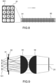
- a set of lighting sources an example of which is illustrated in the Fig. 8 can be used.
- the light sources for example LEDs whose spectra are shown on the Fig. 7 , form point sources combined in the form of a matrix 80.
- the matrix 80 comprises a set of cells 81, each cell comprising all the lighting sources 801, in this example 12 in number.
- the light sources are distributed in each module in a matrix of 3 columns and 4 rows.
- Fig. 9 shows a functional diagram in section of an exemplary lighting device in a color control system according to the present description, in a 0-45 geometry (illumination at 45° relative to the surface).
- the lighting device comprises in addition to the sources 101 a diffuser 91.
- a shutter 92 has been added at the outlet of the diffuser to reduce the angle on the concentration device consisting of two inverted semi-cylindrical lenses 93, 94 of the same focal length.
Landscapes
- Physics & Mathematics (AREA)
- Spectroscopy & Molecular Physics (AREA)
- General Physics & Mathematics (AREA)
- Health & Medical Sciences (AREA)
- Life Sciences & Earth Sciences (AREA)
- Chemical & Material Sciences (AREA)
- Analytical Chemistry (AREA)
- Biochemistry (AREA)
- General Health & Medical Sciences (AREA)
- Immunology (AREA)
- Pathology (AREA)
- Spectrometry And Color Measurement (AREA)
- Circuit Arrangement For Electric Light Sources In General (AREA)
- Non-Portable Lighting Devices Or Systems Thereof (AREA)
Claims (10)
- System (100) zur Echtzeit-Farbkontrolle eines Artikels (10), der auf einem Träger (201, 202) positioniert ist, der sich in einer vorgegebenen Bewegungsrichtung (Y) bewegt, aufweisend:- eine Beleuchtungsvorrichtung (101, 105), die konfiguriert ist, um den sich bewegenden Artikel in aufeinanderfolgenden Beleuchtungszyklen zu beleuchten, wobei jeder Beleuchtungszyklus die aufeinanderfolgende Bildung einer vorgegebenen Anzahl N von Beleuchtungslinien, die unterschiedliche Spektralbänder präsentieren, bei einer gegebenen Frequenz aufweist, N ≥ 4, wobei die Beleuchtungslinien im Wesentlichen senkrecht zur Bewegungsrichtung verlaufen, wobei die Gesamtheit der während eines Beleuchtungszyklus gebildeten N Beleuchtungslinien auf dem sich bewegenden Artikel ein Beleuchtungsband einer vorgegebenen Dimension in der Bewegungsrichtung definiert;- eine Detektionsvorrichtung (102, 106), die konfiguriert ist, um während jedes Beleuchtungszyklus das von dem nacheinander von jeder der Beleuchtungslinien beleuchteten Artikel zurückgestreute Licht zu detektieren, so dass während jedes Beleuchtungszyklus an jedem Punkt (Pk) einer Anzahl vorgegebener Punkte eines senkrecht zur Bewegungsrichtung verlaufenden Observationsbandes (20) eine Anzahl N von Signalen gebildet wird, die jeweils dem von dem Punkt in jedem der Spektralbänder zurückgestreuten Licht entsprechen;- eine Verarbeitungseinheit (104), die konfiguriert ist, um an jedem der Punkte des Observationsbandes und ausgehend von den N Signalen mindestens einen Wert zu bestimmen, der für die Farbe des Punktes repräsentativ ist.
- System zur Farbkontrolle nach Anspruch 1, wobei die Anzahl N von Beleuchtungslinien mit unterschiedlichen Spektralbändern zwischen 8 und 12 beträgt.
- System zur Farbkontrolle nach einem der vorhergehenden Ansprüche, wobei die Beleuchtungsvorrichtung eine Vielzahl von Lichtquellen (101) aufweist, die konfiguriert sind, um nacheinander einen oder mehrere Strahlen in jedem der Spektralbänder auszusenden, und ein oder mehrere optische Elemente (105), die konfiguriert sind, um aus dem einen oder den mehreren in jedem der Spektralbänder ausgesendeten Strahlen eine Beleuchtungslinie in dem Spektralband zu bilden.
- System zur Farbkontrolle nach einem der vorhergehenden Ansprüche, wobei eine Dimension des Observationsbandes in einer Richtung parallel zur Bewegungsrichtung zwischen etwa 0,1 mm und etwa 1 mm beträgt.
- System zur Farbkontrolle nach einem der vorhergehenden Ansprüche, wobei die Detektionsvorrichtung mindestens einen feststehenden Sensor (102) und ein oder mehrere optische Elemente (106) aufweist, die konfiguriert sind, um während jedes Zyklus ein Bild jeder Beleuchtungslinie zu erzeugen, die von dem Artikel auf den Sensor zurückgestreut wird.
- System zur Farbkontrolle nach Anspruch 6, wobei der mindestens eine Sensor monochrom ist.
- Verfahren zur Farbkontrolle eines Artikels auf einem Träger (201, 202), der sich in einer vorgegebenen Bewegungsrichtung bewegt, die folgenden Schritte aufweisend:- Beleuchten des sich bewegenden Artikels mittels einer Beleuchtungsvorrichtung (101, 105) in aufeinanderfolgenden Beleuchtungszyklen, wobei jeder Beleuchtungszyklus die aufeinanderfolgende Bildung einer vorgegebenen Anzahl N von Beleuchtungslinien, die unterschiedliche Spektralbänder präsentieren, bei einer gegebenen Frequenz aufweist, N ≥ 4, wobei die Beleuchtungslinien im Wesentlichen senkrecht zur Bewegungsrichtung verlaufen, wobei die Gesamtheit der während eines Beleuchtungszyklus gebildeten N Beleuchtungslinien auf dem sich bewegenden Artikel ein Beleuchtungsband einer vorgegebenen Dimension in der Bewegungsrichtung definiert;- das Detektieren, mittels einer Detektionsvorrichtung (102, 106), während jedes Beleuchtungszyklus das von dem nacheinander von jeder der Beleuchtungslinien beleuchteten Artikel rückgestreute Licht, so dass während jedes Beleuchtungszyklus an jedem Punkt einer Anzahl vorgegebener Punkte eines senkrecht zur Bewegungsrichtung verlaufenden Observationsbandes (20) eine Anzahl N von Signalen gebildet wird, die jeweils dem von dem Punkt in jedem der Spektralbänder zurückgestreuten Licht entsprechen;- Bestimmen, an jedem der Punkte des Observationsbandes und ausgehend von den N Signalen, von mindestens einem Wert, der für die Farbe des Punktes repräsentativ ist.
- Verfahren zur Farbkontrolle nach Anspruch 7, wobei der mindestens eine farbrepräsentative Wert eine bestimmte Farbabweichung von einem Referenzobjekt aufweist.
- Verfahren zur Farbkontrolle nach einem der Ansprüche 7 oder 8, wobei die Bestimmung des mindestens einen farbrepräsentativen Werts einen Schritt der gewichteten Mittelung von Signalen aufweist, die durch das Detektieren mehrerer Beleuchtungslinien desselben Spektralbands und aufeinanderfolgender Beleuchtungszyklen erfasst werden.
- Verfahren zur Farbkontrolle nach einem der Ansprüche 7 bis 9, das zusätzlich einen vorherigen Schritt zur Kalibrierung der Detektionsvorrichtung aufweist.
Applications Claiming Priority (2)
| Application Number | Priority Date | Filing Date | Title |
|---|---|---|---|
| FR1910487A FR3101144B1 (fr) | 2019-09-23 | 2019-09-23 | Système et procédé de contrôle de la couleur d’un article en déplacement |
| PCT/EP2020/070596 WO2021058172A1 (fr) | 2019-09-23 | 2020-07-21 | Système et procédé de contrôle de la couleur d'un article en déplacement |
Publications (3)
| Publication Number | Publication Date |
|---|---|
| EP4034863A1 EP4034863A1 (de) | 2022-08-03 |
| EP4034863C0 EP4034863C0 (de) | 2024-12-25 |
| EP4034863B1 true EP4034863B1 (de) | 2024-12-25 |
Family
ID=69172961
Family Applications (1)
| Application Number | Title | Priority Date | Filing Date |
|---|---|---|---|
| EP20753682.2A Active EP4034863B1 (de) | 2019-09-23 | 2020-07-21 | System und verfahren zum steuern der farbe eines sich bewegenden gegenstandes |
Country Status (4)
| Country | Link |
|---|---|
| US (1) | US11940328B2 (de) |
| EP (1) | EP4034863B1 (de) |
| FR (1) | FR3101144B1 (de) |
| WO (1) | WO2021058172A1 (de) |
Family Cites Families (16)
| Publication number | Priority date | Publication date | Assignee | Title |
|---|---|---|---|---|
| WO1994025838A1 (en) * | 1993-04-29 | 1994-11-10 | Centre De Recherche Industrielle Du Quebec | Method and apparatus for sensing the color of articles and for classification thereof |
| US6556300B2 (en) * | 2001-05-22 | 2003-04-29 | Xerox Corporation | Color imager bar based spectrophotometer photodetector optical orientation |
| US6975949B2 (en) | 2004-04-27 | 2005-12-13 | Xerox Corporation | Full width array scanning spectrophotometer |
| US7859668B2 (en) * | 2005-12-15 | 2010-12-28 | Honeywell International Inc. | Apparatus and method for illuminator-independent color measurements |
| DE102006019840B4 (de) * | 2006-04-28 | 2009-09-10 | Fraunhofer-Gesellschaft zur Förderung der angewandten Forschung e.V. | Zeilenkamera für spektrale Bilderfassung |
| CN101558147A (zh) * | 2006-12-12 | 2009-10-14 | 皇家飞利浦电子股份有限公司 | 用于细胞分析的方法和设备 |
| WO2008111055A1 (en) * | 2007-03-12 | 2008-09-18 | In-Dot Ltd. | Color sensing for a reader device and the like |
| US7773222B2 (en) | 2008-05-27 | 2010-08-10 | Xerox Corporation | UV enhanced full width array scanning spectrophotometer |
| US7901534B2 (en) | 2008-09-25 | 2011-03-08 | Attends Healthcare Products, Inc. | Method of making diapers with substantially reduced production of discarded waste material |
| DE202012013411U1 (de) * | 2011-04-25 | 2016-11-15 | Terra Bella Technologies Inc. | Systeme für Overhead-Bild- und Videoanzeige |
| US8960845B2 (en) * | 2012-02-07 | 2015-02-24 | Hewlett-Packard Development Company, L.P. | Color analysis |
| FR2987118A1 (fr) * | 2012-02-17 | 2013-08-23 | Franck Hennebelle | Procede et dispositif de mesure de la couleur d'un objet |
| ITBO20130332A1 (it) * | 2013-06-26 | 2014-12-27 | Nuova Sima Spa | Metodo per scansionare una superficie a colori di un articolo e dispositivo che attua tale metodo |
| AT515139B1 (de) * | 2013-12-05 | 2015-09-15 | Ctr Carinthian Tech Res Ag | Vorrichtung und Verfahren zur Ermittlung spektraler Eigenschaften einer Oberfläche |
| CA2962809C (en) * | 2017-03-31 | 2019-02-26 | Centre De Recherche Industrielle Du Quebec | System and method for color scanning a moving article |
| KR102684149B1 (ko) * | 2018-12-10 | 2024-07-11 | 삼성전자주식회사 | 전자 장치 및 그 제어 방법 |
-
2019
- 2019-09-23 FR FR1910487A patent/FR3101144B1/fr active Active
-
2020
- 2020-07-21 US US17/762,578 patent/US11940328B2/en active Active
- 2020-07-21 EP EP20753682.2A patent/EP4034863B1/de active Active
- 2020-07-21 WO PCT/EP2020/070596 patent/WO2021058172A1/fr not_active Ceased
Also Published As
| Publication number | Publication date |
|---|---|
| EP4034863C0 (de) | 2024-12-25 |
| EP4034863A1 (de) | 2022-08-03 |
| US11940328B2 (en) | 2024-03-26 |
| WO2021058172A1 (fr) | 2021-04-01 |
| FR3101144B1 (fr) | 2021-10-15 |
| FR3101144A1 (fr) | 2021-03-26 |
| US20220404203A1 (en) | 2022-12-22 |
Similar Documents
| Publication | Publication Date | Title |
|---|---|---|
| EP2225608B1 (de) | Vorrichtung zur beurteilung einer reifenfläche | |
| US10161796B1 (en) | LED lighting based multispectral imaging system for color measurement | |
| JP3895772B2 (ja) | 紙幣または有価証券などのシート材を検査する装置および方法 | |
| US10564038B2 (en) | Spectral characteristic acquiring apparatus, image forming apparatus, image forming system, image forming apparatus management system, and image forming apparatus management method | |
| EP3034992A2 (de) | Projektor für strukturierte beleuchtung, und 3d-scanner, der einen solchen projektor enthält | |
| EP1084379B1 (de) | Optoelektronische Formerfassung durch chromatische Kodierung mit Beleuchtungsebenen | |
| EP2340467A1 (de) | Bildgeberanordnungs-kalibrationssystem und verfahren | |
| US11994476B2 (en) | Multi-color surface inspection system, method for inspecting a surface, and method for calibrating the multi-color surface inspection system | |
| JP2021113744A (ja) | 撮像システム | |
| EP4034863B1 (de) | System und verfahren zum steuern der farbe eines sich bewegenden gegenstandes | |
| EP2927051B1 (de) | Beleuchtungsvorrichtung mit anpassbarer farbe | |
| EP3230713B1 (de) | Verfahren zur erzeugung eines bildes einer probe und zugehöriges linsenfreies bildgebungssystem | |
| FR2983951A1 (fr) | Dispositif et methode pour la mesure simultanee de la couleur et de la brillance d'une surface | |
| EP4243394A1 (de) | Vorrichtung, system, verfahren und informationsverarbeitungsmedien zur kalibrierung auf der basis eines referenzweisses eines bilderfassungsgeräts | |
| JP2005221401A (ja) | 膜厚測定方法および装置 | |
| FR2722573A1 (fr) | Procede et dispositif de reconnaissance de particularites geometriques de pieces parallelepipediques de section polygonale | |
| CN114729879B (zh) | 使用显示屏后的传感器进行的光学特性测量 | |
| JP2020005053A (ja) | イメージセンサの分光感度測定方法、分光感度測定装置の検査方法及び分光感度測定装置 | |
| FR3036217A1 (fr) | Procede et systeme de determination de couleur | |
| FR2905185A1 (fr) | Illuminateur multispectral a diodes electroluminescentes synchronise avec l'obturateur des appareils photographiques numeriques. | |
| JP2010085388A (ja) | 印刷物の検査方法及び検査装置 | |
| FR2920227A1 (fr) | Procede d'inspection de cartes electroniques par analyse multispectacle. | |
| EP2769536A1 (de) | Automatisches verfahren zur steuerung der farbübereinstimmung mehrfarbiger industrieller oder landwirtschaftlicher lebensmittelprodukte auf deren gesamter oberfläche und für alle farben dieser produkte | |
| US20250271359A1 (en) | Measurement apparatus and measurement method | |
| FR2881232A1 (fr) | Procede de calibration colorimetrique d'un appareil de capture d'image, appareil ainsi calibre et application en colorimetrie |
Legal Events
| Date | Code | Title | Description |
|---|---|---|---|
| STAA | Information on the status of an ep patent application or granted ep patent |
Free format text: STATUS: UNKNOWN |
|
| STAA | Information on the status of an ep patent application or granted ep patent |
Free format text: STATUS: THE INTERNATIONAL PUBLICATION HAS BEEN MADE |
|
| PUAI | Public reference made under article 153(3) epc to a published international application that has entered the european phase |
Free format text: ORIGINAL CODE: 0009012 |
|
| STAA | Information on the status of an ep patent application or granted ep patent |
Free format text: STATUS: REQUEST FOR EXAMINATION WAS MADE |
|
| 17P | Request for examination filed |
Effective date: 20220321 |
|
| AK | Designated contracting states |
Kind code of ref document: A1 Designated state(s): AL AT BE BG CH CY CZ DE DK EE ES FI FR GB GR HR HU IE IS IT LI LT LU LV MC MK MT NL NO PL PT RO RS SE SI SK SM TR |
|
| TPAC | Observations filed by third parties |
Free format text: ORIGINAL CODE: EPIDOSNTIPA |
|
| 19U | Interruption of proceedings before grant |
Effective date: 20220718 |
|
| 19W | Proceedings resumed before grant after interruption of proceedings |
Effective date: 20230703 |
|
| RAP3 | Party data changed (applicant data changed or rights of an application transferred) |
Owner name: VEORIA |
|
| REG | Reference to a national code |
Ref country code: DE Ref legal event code: R079 Free format text: PREVIOUS MAIN CLASS: G01N0021250000 Ipc: G01J0003020000 Ref country code: DE Ref legal event code: R079 Ref document number: 602020043686 Country of ref document: DE Free format text: PREVIOUS MAIN CLASS: G01N0021250000 Ipc: G01J0003020000 |
|
| GRAP | Despatch of communication of intention to grant a patent |
Free format text: ORIGINAL CODE: EPIDOSNIGR1 |
|
| STAA | Information on the status of an ep patent application or granted ep patent |
Free format text: STATUS: GRANT OF PATENT IS INTENDED |
|
| RIC1 | Information provided on ipc code assigned before grant |
Ipc: G01J 3/50 20060101ALI20240219BHEP Ipc: G01J 3/02 20060101AFI20240219BHEP |
|
| DAV | Request for validation of the european patent (deleted) | ||
| DAX | Request for extension of the european patent (deleted) | ||
| INTG | Intention to grant announced |
Effective date: 20240311 |
|
| GRAJ | Information related to disapproval of communication of intention to grant by the applicant or resumption of examination proceedings by the epo deleted |
Free format text: ORIGINAL CODE: EPIDOSDIGR1 |
|
| STAA | Information on the status of an ep patent application or granted ep patent |
Free format text: STATUS: REQUEST FOR EXAMINATION WAS MADE |
|
| GRAP | Despatch of communication of intention to grant a patent |
Free format text: ORIGINAL CODE: EPIDOSNIGR1 |
|
| STAA | Information on the status of an ep patent application or granted ep patent |
Free format text: STATUS: GRANT OF PATENT IS INTENDED |
|
| INTC | Intention to grant announced (deleted) | ||
| INTG | Intention to grant announced |
Effective date: 20240722 |
|
| GRAS | Grant fee paid |
Free format text: ORIGINAL CODE: EPIDOSNIGR3 |
|
| GRAA | (expected) grant |
Free format text: ORIGINAL CODE: 0009210 |
|
| STAA | Information on the status of an ep patent application or granted ep patent |
Free format text: STATUS: THE PATENT HAS BEEN GRANTED |
|
| AK | Designated contracting states |
Kind code of ref document: B1 Designated state(s): AL AT BE BG CH CY CZ DE DK EE ES FI FR GB GR HR HU IE IS IT LI LT LU LV MC MK MT NL NO PL PT RO RS SE SI SK SM TR |
|
| REG | Reference to a national code |
Ref country code: GB Ref legal event code: FG4D Free format text: NOT ENGLISH |
|
| REG | Reference to a national code |
Ref country code: CH Ref legal event code: EP |
|
| REG | Reference to a national code |
Ref country code: DE Ref legal event code: R096 Ref document number: 602020043686 Country of ref document: DE |
|
| REG | Reference to a national code |
Ref country code: IE Ref legal event code: FG4D Free format text: LANGUAGE OF EP DOCUMENT: FRENCH |
|
| U01 | Request for unitary effect filed |
Effective date: 20250123 |
|
| U07 | Unitary effect registered |
Designated state(s): AT BE BG DE DK EE FI FR IT LT LU LV MT NL PT RO SE SI Effective date: 20250129 |
|
| PG25 | Lapsed in a contracting state [announced via postgrant information from national office to epo] |
Ref country code: HR Free format text: LAPSE BECAUSE OF FAILURE TO SUBMIT A TRANSLATION OF THE DESCRIPTION OR TO PAY THE FEE WITHIN THE PRESCRIBED TIME-LIMIT Effective date: 20241225 |
|
| PG25 | Lapsed in a contracting state [announced via postgrant information from national office to epo] |
Ref country code: NO Free format text: LAPSE BECAUSE OF FAILURE TO SUBMIT A TRANSLATION OF THE DESCRIPTION OR TO PAY THE FEE WITHIN THE PRESCRIBED TIME-LIMIT Effective date: 20250325 |
|
| PG25 | Lapsed in a contracting state [announced via postgrant information from national office to epo] |
Ref country code: GR Free format text: LAPSE BECAUSE OF FAILURE TO SUBMIT A TRANSLATION OF THE DESCRIPTION OR TO PAY THE FEE WITHIN THE PRESCRIBED TIME-LIMIT Effective date: 20250326 |
|
| PG25 | Lapsed in a contracting state [announced via postgrant information from national office to epo] |
Ref country code: RS Free format text: LAPSE BECAUSE OF FAILURE TO SUBMIT A TRANSLATION OF THE DESCRIPTION OR TO PAY THE FEE WITHIN THE PRESCRIBED TIME-LIMIT Effective date: 20250325 |
|
| PG25 | Lapsed in a contracting state [announced via postgrant information from national office to epo] |
Ref country code: SM Free format text: LAPSE BECAUSE OF FAILURE TO SUBMIT A TRANSLATION OF THE DESCRIPTION OR TO PAY THE FEE WITHIN THE PRESCRIBED TIME-LIMIT Effective date: 20241225 |
|
| PG25 | Lapsed in a contracting state [announced via postgrant information from national office to epo] |
Ref country code: PL Free format text: LAPSE BECAUSE OF FAILURE TO SUBMIT A TRANSLATION OF THE DESCRIPTION OR TO PAY THE FEE WITHIN THE PRESCRIBED TIME-LIMIT Effective date: 20241225 |
|
| PG25 | Lapsed in a contracting state [announced via postgrant information from national office to epo] |
Ref country code: ES Free format text: LAPSE BECAUSE OF FAILURE TO SUBMIT A TRANSLATION OF THE DESCRIPTION OR TO PAY THE FEE WITHIN THE PRESCRIBED TIME-LIMIT Effective date: 20241225 |
|
| PG25 | Lapsed in a contracting state [announced via postgrant information from national office to epo] |
Ref country code: IS Free format text: LAPSE BECAUSE OF FAILURE TO SUBMIT A TRANSLATION OF THE DESCRIPTION OR TO PAY THE FEE WITHIN THE PRESCRIBED TIME-LIMIT Effective date: 20250425 |
|
| PG25 | Lapsed in a contracting state [announced via postgrant information from national office to epo] |
Ref country code: SK Free format text: LAPSE BECAUSE OF FAILURE TO SUBMIT A TRANSLATION OF THE DESCRIPTION OR TO PAY THE FEE WITHIN THE PRESCRIBED TIME-LIMIT Effective date: 20241225 |
|
| PG25 | Lapsed in a contracting state [announced via postgrant information from national office to epo] |
Ref country code: CZ Free format text: LAPSE BECAUSE OF FAILURE TO SUBMIT A TRANSLATION OF THE DESCRIPTION OR TO PAY THE FEE WITHIN THE PRESCRIBED TIME-LIMIT Effective date: 20241225 |
|
| U20 | Renewal fee for the european patent with unitary effect paid |
Year of fee payment: 6 Effective date: 20250718 |
|
| PGFP | Annual fee paid to national office [announced via postgrant information from national office to epo] |
Ref country code: CH Payment date: 20250820 Year of fee payment: 6 |
|
| PLBE | No opposition filed within time limit |
Free format text: ORIGINAL CODE: 0009261 |
|
| STAA | Information on the status of an ep patent application or granted ep patent |
Free format text: STATUS: NO OPPOSITION FILED WITHIN TIME LIMIT |
|
| 26N | No opposition filed |
Effective date: 20250926 |
|
| GBPC | Gb: european patent ceased through non-payment of renewal fee |
Effective date: 20250721 |