EP4034712B1 - System und verfahren zum aufrichten und halten von stapeln - Google Patents
System und verfahren zum aufrichten und halten von stapeln Download PDFInfo
- Publication number
- EP4034712B1 EP4034712B1 EP20776164.4A EP20776164A EP4034712B1 EP 4034712 B1 EP4034712 B1 EP 4034712B1 EP 20776164 A EP20776164 A EP 20776164A EP 4034712 B1 EP4034712 B1 EP 4034712B1
- Authority
- EP
- European Patent Office
- Prior art keywords
- pile
- ring
- holder
- engaging devices
- vessel
- Prior art date
- Legal status (The legal status is an assumption and is not a legal conclusion. Google has not performed a legal analysis and makes no representation as to the accuracy of the status listed.)
- Active
Links
Images


Classifications
-
- B—PERFORMING OPERATIONS; TRANSPORTING
- B63—SHIPS OR OTHER WATERBORNE VESSELS; RELATED EQUIPMENT
- B63B—SHIPS OR OTHER WATERBORNE VESSELS; EQUIPMENT FOR SHIPPING
- B63B27/00—Arrangement of ship-based loading or unloading equipment for cargo or passengers
- B63B27/16—Arrangement of ship-based loading or unloading equipment for cargo or passengers of lifts or hoists
-
- E—FIXED CONSTRUCTIONS
- E02—HYDRAULIC ENGINEERING; FOUNDATIONS; SOIL SHIFTING
- E02D—FOUNDATIONS; EXCAVATIONS; EMBANKMENTS; UNDERGROUND OR UNDERWATER STRUCTURES
- E02D13/00—Accessories for placing or removing piles or bulkheads, e.g. noise attenuating chambers
- E02D13/04—Guide devices; Guide frames
-
- B—PERFORMING OPERATIONS; TRANSPORTING
- B63—SHIPS OR OTHER WATERBORNE VESSELS; RELATED EQUIPMENT
- B63B—SHIPS OR OTHER WATERBORNE VESSELS; EQUIPMENT FOR SHIPPING
- B63B27/00—Arrangement of ship-based loading or unloading equipment for cargo or passengers
- B63B27/10—Arrangement of ship-based loading or unloading equipment for cargo or passengers of cranes
-
- B—PERFORMING OPERATIONS; TRANSPORTING
- B63—SHIPS OR OTHER WATERBORNE VESSELS; RELATED EQUIPMENT
- B63B—SHIPS OR OTHER WATERBORNE VESSELS; EQUIPMENT FOR SHIPPING
- B63B35/00—Vessels or similar floating structures specially adapted for specific purposes and not otherwise provided for
-
- B—PERFORMING OPERATIONS; TRANSPORTING
- B66—HOISTING; LIFTING; HAULING
- B66C—CRANES; LOAD-ENGAGING ELEMENTS OR DEVICES FOR CRANES, CAPSTANS, WINCHES, OR TACKLES
- B66C23/00—Cranes comprising essentially a beam, boom, or triangular structure acting as a cantilever and mounted for translatory of swinging movements in vertical or horizontal planes or a combination of such movements, e.g. jib-cranes, derricks, tower cranes
- B66C23/18—Cranes comprising essentially a beam, boom, or triangular structure acting as a cantilever and mounted for translatory of swinging movements in vertical or horizontal planes or a combination of such movements, e.g. jib-cranes, derricks, tower cranes specially adapted for use in particular purposes
- B66C23/36—Cranes comprising essentially a beam, boom, or triangular structure acting as a cantilever and mounted for translatory of swinging movements in vertical or horizontal planes or a combination of such movements, e.g. jib-cranes, derricks, tower cranes specially adapted for use in particular purposes mounted on road or rail vehicles; Manually-movable jib-cranes for use in workshops; Floating cranes
- B66C23/52—Floating cranes
-
- E—FIXED CONSTRUCTIONS
- E02—HYDRAULIC ENGINEERING; FOUNDATIONS; SOIL SHIFTING
- E02B—HYDRAULIC ENGINEERING
- E02B17/00—Artificial islands mounted on piles or like supports, e.g. platforms on raisable legs or offshore constructions; Construction methods therefor
- E02B17/04—Equipment specially adapted for raising, lowering, or immobilising the working platform relative to the supporting construction
-
- E—FIXED CONSTRUCTIONS
- E02—HYDRAULIC ENGINEERING; FOUNDATIONS; SOIL SHIFTING
- E02D—FOUNDATIONS; EXCAVATIONS; EMBANKMENTS; UNDERGROUND OR UNDERWATER STRUCTURES
- E02D15/00—Handling building or like materials for hydraulic engineering or foundations
- E02D15/08—Sinking workpieces into water or soil inasmuch as not provided for elsewhere
-
- E—FIXED CONSTRUCTIONS
- E02—HYDRAULIC ENGINEERING; FOUNDATIONS; SOIL SHIFTING
- E02D—FOUNDATIONS; EXCAVATIONS; EMBANKMENTS; UNDERGROUND OR UNDERWATER STRUCTURES
- E02D7/00—Methods or apparatus for placing sheet pile bulkheads, piles, mouldpipes, or other moulds
-
- F—MECHANICAL ENGINEERING; LIGHTING; HEATING; WEAPONS; BLASTING
- F03—MACHINES OR ENGINES FOR LIQUIDS; WIND, SPRING, OR WEIGHT MOTORS; PRODUCING MECHANICAL POWER OR A REACTIVE PROPULSIVE THRUST, NOT OTHERWISE PROVIDED FOR
- F03D—WIND MOTORS
- F03D13/00—Assembly, mounting or commissioning of wind motors; Arrangements specially adapted for transporting wind motor components
- F03D13/20—Arrangements for mounting or supporting wind motors; Masts or towers for wind motors
- F03D13/201—Towers
- F03D13/203—Lattice truss
-
- F—MECHANICAL ENGINEERING; LIGHTING; HEATING; WEAPONS; BLASTING
- F03—MACHINES OR ENGINES FOR LIQUIDS; WIND, SPRING, OR WEIGHT MOTORS; PRODUCING MECHANICAL POWER OR A REACTIVE PROPULSIVE THRUST, NOT OTHERWISE PROVIDED FOR
- F03D—WIND MOTORS
- F03D13/00—Assembly, mounting or commissioning of wind motors; Arrangements specially adapted for transporting wind motor components
- F03D13/20—Arrangements for mounting or supporting wind motors; Masts or towers for wind motors
- F03D13/201—Towers
- F03D13/205—Connection means, e.g. joints between segments
-
- F—MECHANICAL ENGINEERING; LIGHTING; HEATING; WEAPONS; BLASTING
- F03—MACHINES OR ENGINES FOR LIQUIDS; WIND, SPRING, OR WEIGHT MOTORS; PRODUCING MECHANICAL POWER OR A REACTIVE PROPULSIVE THRUST, NOT OTHERWISE PROVIDED FOR
- F03D—WIND MOTORS
- F03D13/00—Assembly, mounting or commissioning of wind motors; Arrangements specially adapted for transporting wind motor components
- F03D13/20—Arrangements for mounting or supporting wind motors; Masts or towers for wind motors
- F03D13/25—Arrangements for mounting or supporting wind motors; Masts or towers for wind motors specially adapted for offshore installation
-
- F—MECHANICAL ENGINEERING; LIGHTING; HEATING; WEAPONS; BLASTING
- F03—MACHINES OR ENGINES FOR LIQUIDS; WIND, SPRING, OR WEIGHT MOTORS; PRODUCING MECHANICAL POWER OR A REACTIVE PROPULSIVE THRUST, NOT OTHERWISE PROVIDED FOR
- F03D—WIND MOTORS
- F03D80/00—Details, components or accessories not provided for in groups F03D1/00 - F03D17/00
-
- B—PERFORMING OPERATIONS; TRANSPORTING
- B63—SHIPS OR OTHER WATERBORNE VESSELS; RELATED EQUIPMENT
- B63B—SHIPS OR OTHER WATERBORNE VESSELS; EQUIPMENT FOR SHIPPING
- B63B75/00—Building or assembling floating offshore structures, e.g. semi-submersible platforms, SPAR platforms or wind turbine platforms
-
- E—FIXED CONSTRUCTIONS
- E02—HYDRAULIC ENGINEERING; FOUNDATIONS; SOIL SHIFTING
- E02B—HYDRAULIC ENGINEERING
- E02B17/00—Artificial islands mounted on piles or like supports, e.g. platforms on raisable legs or offshore constructions; Construction methods therefor
- E02B17/04—Equipment specially adapted for raising, lowering, or immobilising the working platform relative to the supporting construction
- E02B17/06—Equipment specially adapted for raising, lowering, or immobilising the working platform relative to the supporting construction for immobilising, e.g. using wedges or clamping rings
-
- E—FIXED CONSTRUCTIONS
- E02—HYDRAULIC ENGINEERING; FOUNDATIONS; SOIL SHIFTING
- E02B—HYDRAULIC ENGINEERING
- E02B17/00—Artificial islands mounted on piles or like supports, e.g. platforms on raisable legs or offshore constructions; Construction methods therefor
- E02B2017/0039—Methods for placing the offshore structure
-
- E—FIXED CONSTRUCTIONS
- E02—HYDRAULIC ENGINEERING; FOUNDATIONS; SOIL SHIFTING
- E02B—HYDRAULIC ENGINEERING
- E02B17/00—Artificial islands mounted on piles or like supports, e.g. platforms on raisable legs or offshore constructions; Construction methods therefor
- E02B2017/0056—Platforms with supporting legs
- E02B2017/0065—Monopile structures
-
- E—FIXED CONSTRUCTIONS
- E02—HYDRAULIC ENGINEERING; FOUNDATIONS; SOIL SHIFTING
- E02B—HYDRAULIC ENGINEERING
- E02B17/00—Artificial islands mounted on piles or like supports, e.g. platforms on raisable legs or offshore constructions; Construction methods therefor
- E02B2017/0091—Offshore structures for wind turbines
-
- E—FIXED CONSTRUCTIONS
- E02—HYDRAULIC ENGINEERING; FOUNDATIONS; SOIL SHIFTING
- E02D—FOUNDATIONS; EXCAVATIONS; EMBANKMENTS; UNDERGROUND OR UNDERWATER STRUCTURES
- E02D27/00—Foundations as substructures
- E02D27/32—Foundations for special purposes
- E02D27/52—Submerged foundations, i.e. submerged in open water
- E02D27/525—Submerged foundations, i.e. submerged in open water using elements penetrating the underwater ground
Definitions
- the invention relates to a pile upending and holding system configured to be mounted on a vessel, e.g. for installation of a pile, e.g. a monopile, adapted to support an offshore wind turbine.
- the invention further relates to a vessel comprising such a system and a method for using the system.
- Installation of an offshore wind turbine comprises the step of installing the foundation, often in the form of a pile, e.g. a monopile, of the offshore wind turbine.
- a pile is installed by driving the pile into the seabed after which the upper part of the wind turbine is arranged on top of the pile.
- the pile is initially supported on a jack-up vessel in a horizontal orientation.
- the pile is firstly upended, i.e. is pivoted in an upright position. Subsequently, the pile is lowered to the seabed at the pile installation location. Finally the pile, more in particular a lower part of the pile, is driven into the seabed.
- a first longitudinal end of the pile is gripped by the gripping tool of the lifting device and lifted by the lifting device while a second longitudinal end of the pile is vertically supported by the upending tool of the system.
- the first longitudinal end moves upwards relative to the second longitudinal end, so that the pile pivots upwards.
- the pivoting continues until the pile is in a substantially vertical orientation.
- the upending tool, or at least a part thereof that is supporting the second longitudinal end of the pile is pivotable around a substantially horizontal axis relative to the vessel.
- Publication EP 3 517 479 discloses a pile upending and holding system, comprising an upending tool and holding tool. Both tools are mounted to an edge of the vessel. A crane is used to lift the pile into the upending tool and for consequently lifting the first longitudinal end to upend the pile while supported by the upending tool. Thereafter the pile is transferred by means of the crane to the holding tool, after which the crane is operated for lowering the pile towards the seabed and for the consequent pile driving, while the pile is held by the holding tool to maintain the horizontal position of the pile.
- the inventive tool being configured for both upending of the pile and holding during lowering with X-Y compensation, makes that the tool is able to provide this counteractive force moment not only during the stage of upending, but also during holding and guiding the pile, prior to and during lowering.
- the catching and retarding mechanism comprises one or more hydraulic cylinders, which are fully extended when engaging the pile holder at the predetermined backward tilting angle and shorten as the backward tilting angle decreases.
- the catching and retarding mechanism is releasably connectable, e.g. automatically, to the pile holder directly after engagement of the pile holder, e.g. with a forward end thereof which is a free end prior to the connection.
- the lower and upper pile engaging devices are each movable relative to the respective ring structure of the lower and upper ring, respectively.
- the active radial movability of the pile engaging devices e.g. allows for radial (re)positioning of the pile being held.
- the active radial movability for example enable the pile holder to be adjustable to a range of pile diameters, so that it is configured to hold piles with different diameters.
- the pile engaging devices may prior to receipt of a pile be moved radially inwardly in case of a small diameter pile, and moved radially outwardly for holding a large diameter pile.
- the system comprises such ring damping mechanism in one of, or in both the rings of the pile holder, e.g. configured to suppress oscillation during upending and lowering, and/or supress undesired tilting of the upended pile.
- the ring damping system passively damps out movements of the pile in the radial plane of the ring, while draining energy from the radial movements of the pile engaging devices involved in such oscillation or tilting.
- Such passive ring damping mechanism e.g. comprises radially extending cylinders passively shortening and extending upon radial movements of the pile engaging devices relative to the ring structure of the respective ring.
- one ring damping mechanism is provided, e.g. in the upper ring.
- the pile engaging devices of one of the rings e.g. of the upper ring, have a fixed angular position relative to the ring structure of the respective ring.
- the lower pile engaging devices may be movable radially as well, such as to be able to disengage the pile exterior after adjustment of the angular position, while the upper pile engaging devices remain engaged with the pile exterior. This enables, the lower pile engaging devices to be movable back along the same arc segment to their initial angular positions while clear from the pile exterior, and consequently movable radially inwardly to engage the pile exterior again.
- an adjustment process is made possible to change of the angular position of the pile relative to its longitudinal axis, while during the complete process the pile continuously remains engaged by multiple of the pile engaging devices, namely at least those of one of the rings.
- the number of the pile engaging devices of the lower ring is equal to the number of the pile engaging devices of the upper ring, so that during the adjustment process the pile continuously remains engaged by half of the pile engaging devices.
- the pile foot end support comprises one or more pivotal arms that are movable into an operative position wherein the one or more pivotal arms extend underneath the longitudinal end portion of the pile and an opened position wherein the one or more pivotal arms are cleared from the pile end portion.
- the system comprises a deployable noise-mitigation screen having a storage device that is mounted on the pile holder below the lower ring, e.g. between the lower ring and the pile foot end support.
- the pile holder is provided with a storage cage for a screen.
- the support assembly provides compensation for wave-induced motion of the vessel to maintain a predetermined X-Y location of the pile holder independent of the wave-induced motion of the vessel at least in step g.
- a lifting device e.g. a crane, on the vessel may be used to perform step c, even as the lifting of lifting the second longitudinal end portion of the pile in step e and the lowering of step g, as is known in the art.
- the method comprises counteracting of a tilting of the pile during any of steps e, f and g, by the pile engaging devices of the respective rings applying opposite radial forces to the pile create a force moment around the tilt axis in the opposite direction of the tilting of the pile.
- the method may comprise applying a force moment to the pile holder as a whole, by means of one or more actuators, e.g. a forward or backward pushing or pulling force at a location on the pile holder offset from the tilt axis, so that this force moment is transferred to the pile via the rings engaging the pile.
- the method may comprise pushing the pile forward relative to the ring structure of one of the rings by the pile engaging devices thereof, and pushing the pile backward relative to the ring structure of the other one of the rings by the pile engaging devices thereof, by one or more actuators operating between the respective ring structure and pile engaging devices.
- the method comprises engaging the pile holder by the catching and retarding mechanism as soon as the pile holder reaches a predetermined backward tilting angle of for example between 45 and 5 degrees from vertical, e.g. between 25 and 5 degrees, e.g. between 15 and 5 degrees.
- the pile exterior is clear from the pile engaging devices of the other one of the rings, e.g. the upper ring.
- the angular adjustment process comprises, prior to the angular movement, clearing the upper pile engaging devices of the upper ring from the pile exterior, e.g. by moving these radially outwards relative to the ring structure such as to disengage the exterior of the pile.
- the process may further comprise, thereafter, engaging the exterior of the pile by the pile engaging devices of the other one of the rings, e.g. the upper ring, again.
- the angular adjustment process comprises, prior to the moving back, clearing the pile engaging devices of the one of the rings from the pile exterior, e.g. by moving these radially outwards relative to the ring structure such as to disengage the exterior of the pile, and may further comprise, thereafter, engaging the exterior of the pile by the pile engaging devices of the one of the rings again.
- the pile holder is provided, below the lower ring thereof, with a pile foot end support that is secured to the pile holder frame and that is configured to engage with a longitudinal end portion of a pile in order to limit longitudinal movement of the pile, at least during upending of the pile.
- the invention in a third aspect thereof, relates to a system for holding a pile which is configured to be mounted on a vessel.
- the system comprises a support assembly configured to be mounted on the vessel, e.g. on a deck of the vessel, and a pile holder.
- the support assembly is configured to provide compensation for motion, e.g. wave-induced motion, of the vessel to maintain a predetermined X-Y location of the pile holder independent of the motion of the vessel.
- Each ring of the pile holder preferably, comprises a ring base fixed to the pile holder frame and one or more movable jaws, e.g. two semi-circular jaws, which are movable such as to move the jaws between an opened position and a closed position.
- the rings In the opened position, the rings define an entry opening of the pile holder for entry of the pile into the pile holder to extend through the lower and upper ring.
- the ring In the closed position, the ring forms a closed annulus enclosing the pile extending through the rings.
- the pile holder is provided with a pile foot end support that is secured to the pile holder frame and that is configured to engage with a longitudinal end portion of a pile in order to limit longitudinal movement of the pile, at least during upending of the pile.
- the system is a system for holding and upending a pile as described in relation to the first aspect. It is noted that in as far technically possible, features and embodiments described in relation to the first and/or second aspect may be applied to the system according to the third aspect for providing similar effects and advantages.
- the invention in a fourth aspect thereof, relates to a system for holding a pile which is configured to be mounted on a vessel.
- the system comprises a support assembly configured to be mounted on the vessel, e.g. on a deck of the vessel, and a pile holder.
- the pile holder has a center axis and is mounted on the support assembly such as to be tiltable about a substantially horizontal tilt axis relative to the support assembly, e.g. between a horizontal orientation, in which the center axis is substantially horizontal, and a vertical orientation, in which the center axis is substantially vertical, e.g. while holding the pile longitudinally along the center axis.
- Each ring comprises a ring structure and multiple pile engaging devices connected to the ring structure of the respective ring, distributed about the circumference of the ring.
- the upper ring comprises multiple upper pile engaging devices
- the lower ring comprises multiple pile engaging devices.
- Each pile engaging device is adapted to engage an exterior of the pile extending through the ring such as to hold the pile longitudinally along the center axis and guide the pile while it moves along the center axis, e.g. each pile engaging device comprising one or more pile guiding rollers.
- the pile engaging devices of at least one of the rings are radially movable with respect to the ring structure of the respective ring while engaging the pile exterior, such as to radially move the engaged pile within the ring.
- the pile engaging devices of both of the rings are radially movable, preferably the lower pile engaging devices being independently movable from the upper pile engaging devices.
- the radial movability may be such as to allow varying circumferences to be engaged, to horizontally position the pile, to dampen oscillations while draining energy therefrom, and/or to counteract undesired tilting of the pile.
- the system is a system for holding and upending a pile as described in relation to the first and/or second aspect. It is noted that in as far as technically possible, one or more features and embodiments described in relation to the first or second aspect may be applied to the system according to the fourth aspect for providing similar effects and advantages.
- the pile holder has a center axis and is mounted on the support assembly such as to be tiltable about a substantially horizontal tilt axis relative to the support assembly, e.g. between a horizontal orientation, in which the center axis is substantially horizontal, and a vertical orientation, in which the center axis is substantially vertical, e.g. while holding the pile longitudinally along the center axis during upending.
- the pile holder comprises a lower ring and an upper ring mutually spaced along the center axis, and each adapted to enclose the pile extending therethrough with a longitudinal axis of the pile extending along the center axis of the pile holder, and a pile holder frame supporting the lower and upper rings.
- Each ring comprises a ring structure and multiple pile engaging devices connected to the ring structure of the respective ring, distributed about the circumference of the ring.
- the upper ring comprises multiple upper pile engaging devices
- the lower ring comprises multiple pile engaging devices.
- Each pile engaging device is adapted to engage an exterior of the pile extending through the ring such as to hold the pile longitudinally along the center axis and guide the pile while it moves along the center axis, e.g. each pile engaging device comprising one or more pile guiding rollers.
- the pile engaging devices of at least one of the lower ring and the upper ring are movable relative to the respective ring structure along an arc segment of the closed annulus formed by the respective ring, e.g. while remaining engaged with the pile exterior, so as to allow for adaptation of the angular position of the pile engaging devices relative to the ring structure and, possibly, for moving the held pile over an angle around its vertically oriented longitudinal axis into a desired angular position.
- the pile engaging devices of one of the rings e.g. of the upper ring, have a fixed angular position relative to the ring structure of the respective ring.
- the pile engaging devices of both rings are angularly movable as described.
- both the upper and lower pile engaging devices allow movement of the held pile over an angle around its longitudinal axis into a desired angular position of the pile relative to the pile engaging devices in the angular movement direction.
- This embodiment enables to firstly move the upper pile engaging devices over their respective arc segments, and consequently the lower pile engaging devices over their respective arc segments. This enables to move the pile over the total angular range of the respective arc segments together.
- the lower pile engaging devices are movable along the arc segment of the lower ring while remaining engaged with the pile exterior as described, and the upper pile engaging devices have a fixed angular position as described.
- the upper pile engaging devices are radially movable by means of one or more actuators. This enables the upper pile engaging devices to move outwardly to disengage the pile exterior and inwardly to engage the pile exterior again.
- the upper pile engaging devices are movable to be clear from the pile exterior prior to movement of the lower pile engaging devices along the arc segment to adjust the angular position thereof, and of the held pile, so that the pile can move around its longitudinal axis unhindered.
- the upper pile engaging devices are movable radially inwardly, to be able to consequently engage the pile exterior again after the angular movement of the pile.
- the lower pile engaging devices may be movable radially as well, such as to be able to disengage the pile exterior after adjustment of the angular position, while the upper pile engaging devices remain engaged with the pile exterior. This enables, the lower pile engaging devices to be movable back along the same arc segment to their initial angular positions while clear from the pile exterior, and consequently movable radially inwardly to engage the pile exterior again.
- an adjustment process is made possible to change of the angular position of the pile relative to its longitudinal axis, while during the complete process the pile continuously remains engaged by multiple of the pile engaging devices, namely at least those of one of the rings.
- the number of the pile engaging devices of the lower ring is equal to the number of the pile engaging devices of the upper ring, so that during the adjustment process the pile continuously remains engaged by half of the pile engaging devices.
- the above may also be applied similarly in a reverse embodiment wherein the upper pile engaging devices are angularly movable and the upper pile engaging devices have a fixed angular position.
- the at least one ring of the pile holder preferably, comprises a ring base fixed to the pile holder frame and one or more movable jaws, e.g. two semi-circular jaws, which are movable between an opened position and a closed position.
- the jaws between free ends thereof define an entry opening of the pile holder for entry of the pile into the pile holder to extend through the lower and upper ring.
- the ring In the closed position, the ring forms a closed annulus enclosing the pile extending through the rings.
- the pile holder is provided with a pile foot end support that is secured to the pile holder frame and that is configured to engage with a longitudinal end portion of a pile in order to limit longitudinal movement of the pile, at least during upending of the pile.
- a sixth aspect of the invention relates to the situation that a pile, e.g. monopile to be installed as foundation of an offshore wind turbine, which is held in vertical orientation in a pile holder that is mounted on a vessel exhibits an undesirable motion during the installation process, e.g. due to the lower pile end sliding away sideways, e.g. during the landing or during the pile driving phase, e.g. due soil related effects.
- this situation may lead to forces that cannot be absorbed by the pile holder and/or the vessel.
- the sixth aspect of the invention provides for a method for installation of a pile in the seabed, e.g. a monopile to be installed as foundation of an offshore wind turbine, wherein use is made of a pile holding system mounted on a vessel, comprising:
- the above steps are performed automatically.
- the step of opening the jaw(s) can be done, as preferred, in overlap with moving the pile holder away from the vessel.
- the pile holder of the sixth aspect of the invention may have just one ring, or may have another configuration, e.g. may have two rings as disclosed herein.
- the sixth aspect of the invention also relates to a pile holding system for installation of a pile in the seabed, wherein the pile holding system is configured for mounting on a vessel or is mounted on a vessel, comprising:
- the system comprises a computerized controller configured, e.g. programmed, to perform an emergency routine that upon start of the routine, e.g. by operation of an emergency button and/or by automated evaluation of one or more parameters related to the pile installation process:
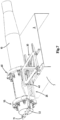
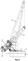
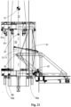
- the vessel is equipped with a crane 2 configured to lift a monopile 10 for an offshore wind turbine.
- the vessel 1 has a deck 3 on which one or more monopiles 10 are stored in horizontal orientation, e.g. transverse to a longitudinal axis of the vessel.
- the system 20 comprises a support assembly 30 that is configured to be mounted on the vessel 1, e.g. on a deck 3 of the vessel, and a pile holder 50.
- the support assembly 30 is configured to provide compensation for wave-induced motion of the vessel 1 to maintain a predetermined X-Y location of the pile holder 50 independent of the wave-induced motion of the vessel 1.
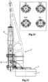
- the upper ring 60 is vertically above the lower ring 55 when the pile holder 50 is in substantially vertical orientation.
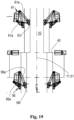
- Each of the lower ring and upper ring 55, 60 comprises a ring base 55b, 60b fixed to the pile holder frame 53, indicated in the top views of figure 4 and figures 22a ,b.
- Each ring 55, 60 further comprises two semi-circular movable jaws 58, 59, 62, 63, each jaw being movable such as to move the rings between a closed position, wherein the rings form a closed annulus, and an opened position.
- the jaws 58, 59, 62, 63 are thereto each pivotable around respective longitudinal pivot axes.
- the upper ring 60 is shown with the jaw 63 opened and jaw 62 closed, and in figure 22b with both jaws 62, 62 opened.
- the rings 55,60 between free ends thereof define an entry opening 52 of the pile holder 50 for entry of the pile 10 into the pile holder 50 to extend through the lower and upper ring 55, 60 with the longitudinal axis 11 of the pile 10 extending along the center axis 51.
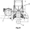
- the entry opening 52 is indicated in figures 18 and 22b .
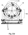
- the respective ring 55, 60 forms a closed annulus enclosing the pile 10 extending through the rings 55, 60 as shown for the lower ring in figure 22c , and for both rings in figures 1 - 13 , 15 , 17 .
- Figure 10 illustrates the system 20 on a vessel 1 after step b1 and figure 11 after step d.
- the system 20 is illustrated halfway step e, and in figure 13 after step e.
- FIG 22d another use of the angular movability of the pile engaging devices 56, 61 is shown.
- a part of the devices may be moved towards the bottom part of the ring bases, so that the pile 10 is supported vertically by multiple pile engaging devices in this orientation.
- the devices 56, 61 may later be moved to be more evenly distributed over the circumference in the vertical orientation.
Landscapes
- Engineering & Computer Science (AREA)
- General Engineering & Computer Science (AREA)
- Life Sciences & Earth Sciences (AREA)
- Mechanical Engineering (AREA)
- Chemical & Material Sciences (AREA)
- Combustion & Propulsion (AREA)
- Structural Engineering (AREA)
- Civil Engineering (AREA)
- Mining & Mineral Resources (AREA)
- General Life Sciences & Earth Sciences (AREA)
- Paleontology (AREA)
- Sustainable Energy (AREA)
- Sustainable Development (AREA)
- Ocean & Marine Engineering (AREA)
- Placing Or Removing Of Piles Or Sheet Piles, Or Accessories Thereof (AREA)
Claims (15)
- System (20) zum Aufrichten und Halten eines Pfahls, das dafür ausgelegt ist, auf einem Schiff (1) montiert zu werden, z. B. für die Installation eines Pfahls (10), der dazu eingerichtet ist, eine Offshore-Windturbine zu tragen, umfassend:- eine Halteanordnung (30), die dafür ausgelegt ist, auf dem Schiff (1), z. B. auf einem Deck (3) des Schiffes, montiert zu werden,- einen Pfahlhalter (50), der kippbar an der Halteanordnung (30) montiert ist, wobei der Pfahlhalter (50) um eine im Wesentlichen horizontale Kippachse (40) relativ zur Halteanordnung (30) zwischen einer horizontalen Ausrichtung, in der der Pfahlhalter einen Pfahl in einer im Wesentlichen horizontalen Ausrichtung halten kann, und einer vertikalen Ausrichtung kippbar ist, wobei der Pfahlhalter umfasst:- einen unteren Ring (55),- einen oberen Ring (60),- einen Pfahlhalterrahmen (53), der den unteren Ring (55) und den oberen Ring (60) trägt, wobei sich der obere Ring (60) senkrecht über dem unteren Ring (55) befindet, wenn sich der Pfahlhalter (50) in im Wesentlichen vertikaler Ausrichtung befindet,wobei jeder vom unteren Ring (55) und dem oberen Ring (60) mehrere Pfahleingriffsvorrichtungen (56, 61) umfasst, die über den Umfang des jeweiligen Rings verteilt sind, wobei jede Pfahleingriffsvorrichtung dazu eingerichtet ist, mit einer Außenseite eines Pfahls (10) in Eingriff zu kommen, der sich durch den unteren und den oberen Ring (55, 60) erstreckt, wobei z. B. jede Pfahleingriffsvorrichtung (56, 61) eine oder mehrere Pfahlführungsrollen umfasst,wobei jeder vom unteren Ring (55) und dem oberen Ring (60) eine am Pfahlhalterrahmen (53) fixierte Ringbasis und eine oder mehrere bewegliche Backen (58, 59, 62, 63), z. B. zwei halbkreisförmige Backen, umfasst, wobei jede Backe zwischen einer geschlossenen Position, in der der jeweilige Ring (55, 60) einen geschlossenen Ring bildet, und einer geöffneten Position bewegbar ist,wobei der Pfahlhalter (50) unterhalb seines unteren Rings (55) mit einer Pfahlfußendstütze (70) bereitgestellt ist, die am Pfahlhalterrahmen (53) befestigt ist und dafür ausgelegt ist, mit dem Fußende eines Pfahls (10) in Eingriff zu kommen, um Längsbewegung des Pfahls (10) zumindest während des Aufrichtens des Pfahls (10) zu begrenzen,dadurch gekennzeichnet, dass:
die Halteanordnung (30) dafür ausgelegt ist, Kompensation für Bewegung des Schiffes (1) bereitzustellen, um eine vorbestimmte X-Y-Position des Pfahlhalters (50) unabhängig von der Bewegung, z. B. wellen- und/oder strömungsinduzierter Bewegung, des Schiffes (1) beizubehalten. - System (20) nach Anspruch 1, wobei das Schiff (1), an dem das System zur Montage ausgelegt ist, eine X-Richtung, die horizontal in einer Ebene entlang der Länge des Schiffes verläuft, und eine Y-Richtung hat, die horizontal in einer Querebene des Schiffes verläuft, und wobei die im Wesentlichen horizontale Kippachse (40) in der Y-Richtung verläuft.
- System (20) nach Anspruch 1 oder 2, wobei die Kippachse (40) in der vertikalen Ausrichtung des Pfahlhalters (50) in der X-Richtung weiter vorne von der Position angeordnet ist, an der die Halteanordnung (30) am Schiff (1) montiert ist, als eine Mittelachse (51) des Pfahlhalters.
- System (20) nach einem oder mehreren der Ansprüche 1 - 3, wobei die Kippachse (40) zwischen dem unteren Ring (55) und dem oberen Ring (60), vorzugsweise in der Mitte dazwischen, angeordnet ist.
- System (20) nach einem oder mehreren der Ansprüche 1 - 4, wobei die Halteanordnung (30) umfasst: eine oder mehrere Y-Schienen (31), die sich in der Y-Richtung erstrecken und dafür ausgelegt sind, auf dem Schiff (1), z. B. auf einem Deck (3) des Schiffes, montiert zu werden, einen Positionierungsrahmen (32), der auf der einen oder den mehreren Y-Schienen (31) in der Y-Richtung beweglich gelagert ist, wobei der Positionierungsrahmen (32) mit einer oder mehreren X-Schienen (33) bereitgestellt ist, die sich im Wesentlichen horizontal in der X-Richtung erstrecken, und einen Halterahmen (34), der auf der einen oder den mehreren X-Schienen (33) in der X-Richtung beweglich gelagert ist, wobei der Pfahlhalter (50) vom Halterahmen (34) um die Kippachse (40) kippbar gelagert ist.
- System (20) nach einem oder mehreren der Ansprüche 1 - 5, wobei die Halteanordnung (30) beabstandet von der Kippachse (40) entlang der Mittellinie, z. B. unterhalb der Kippachse, wenn sie sich in vertikaler Ausrichtung befindet, mit einem Fang- und Verzögerungsmechanismus (42) bereitgestellt ist, wobei der Fang- und Verzögerungsmechanismus (42) dafür ausgelegt ist, in einem Bereich von Winkeln der Mittelachse (51) von einem vorbestimmten Rückwärtskippwinkel bis zu einer vertikalen Ausrichtung mit dem Pfahlhalter (50) in Eingriff zu kommen und eine Kraft auf den Pfahlhalter in Längsrichtung beabstandet von der Kippachse auszuüben, z. B. eine Vorwärtskraft unterhalb der Kippachse, um etwa eine Vorwärtskippbewegung des Pfahlhalters und des dadurch gehaltenen Pfahls zu verlangsamen.
- System (20) nach einem oder mehreren der Ansprüche 1 - 6, wobei die unteren und/oder die oberen Pfahleingriffsvorrichtungen (56, 61) in mindestens einer radialen Richtung relativ zur jeweiligen Ringstruktur beweglich sind,z. B. wobei die unteren Pfahleingriffsvorrichtungen (56) unabhängig von den oberen Pfahleingriffsvorrichtungen (61) beweglich sind, z. B. alle Pfahleingriffsvorrichtungen einzeln und unabhängig voneinander beweglich sind,z. B. um beim Absenken des Pfahls (10) den Pfahl mit einem in Längsrichtung und/oder tangential variierenden Außenumfang kontinuierlich zu erfassen und zu führen.
- System (20) nach Anspruch 7, wobei die unteren und/oder die oberen Pfahleingriffsvorrichtungen (56, 61) durch einen oder mehrere jeweilige Aktuatoren des jeweiligen Rings (55, 60) aktiv radial beweglich sind, z. B. aktiv radial beweglich:- um etwa den Pfahl (10) zu erfassen und/oder freizugeben, und/oder- während des Eingriffs mit dem Pfahl, etwa um die Position des Pfahls relativ zum jeweiligen Ring in der Radialebene einzustellen, z. B. um die horizontale Position des Pfahls einzustellen und/oder um einer Verkippung des Pfahls entgegenzuwirken, wobei z. B. die unteren Pfahleingriffsvorrichtungen unabhängig von den unteren Pfahleingriffsvorrichtungen beweglich sind.
- System (20) nach Anspruch 7 oder 8, wobei die oberen und/oder die unteren Pfahleingriffsvorrichtungen (56, 61), z. B. nur die oberen Pfahleingriffsvorrichtungen (61), dafür ausgelegt sind, radiale Bewegungen des Pfahls (10) innerhalb des jeweiligen Rings zu absorbieren und/oder zumindest teilweise zu kompensieren, z. B. diese Bewegungen vollständig zu kompensieren, z. B. passiv, wobei das System beispielsweise einen passiven Ringdämpfungsmechanismus in einem oder in beiden Ringen (55, 60) des Pfahlhalters (50), z. B. nur im oberen Ring (55), zwischen den Pfahleingriffsvorrichtungen (56, 61) des jeweiligen Rings und der Ringstruktur desselben umfasst, dafür ausgelegt sind, Schwingungen beim Aufrichten und Absenken des Pfahls (10) zu unterdrücken, und/oder unerwünschtes Kippen des aufgerichteten Pfahls (10) zu unterdrücken, während er Energie aus den radialen Bewegungen der jeweiligen Pfahleingriffsvorrichtungen ableitet, die durch die Schwingungen und/oder das Kippen des Pfahls induziert werden.
- System (20) nach einem oder mehreren der Ansprüche 1 - 9, wobei die Pfahleingriffsvorrichtungen (56) von mindestens einem vom unteren Ring (55) und dem oberen Ring (60), z. B. nur vom unteren Ring (55), relativ zur Ringstruktur des jeweiligen Rings (55) entlang eines jeweiligen Bogensegments des durch den Ring (55) gebildeten geschlossenen Rings bewegbar sind, während sie mit der Pfahlaußenseite in Eingriff bleiben, um eine Anpassung der Winkelposition der Pfahleingriffsvorrichtungen (56) relativ zur Ringstruktur des Rings (55) zu ermöglichen, wodurch der Pfahl um die Mittelachse gedreht wird, wobei beispielsweise die oberen und/oder die unteren Pfahleingriffsvorrichtungen, z. B. nur die oberen Pfahleingriffsvorrichtungen (61), eine feste Winkelposition relativ zur Ringstruktur des jeweiligen Rings (60) aufweisen und dafür ausgelegt sind, Winkelbewegung des Pfahls (10) relativ zu den Pfahleingriffsvorrichtungen zu ermöglichen,
z. B. wobei die fest positionierten Pfahleingriffsvorrichtungen- durch einen oder mehrere Aktuatoren, die radial nach außen zum Freigeben der Pfahlaußenseite bewegt werden können, und radial nach innen zum Erfassen der Pfahlaußenseite bewegt werden können, und/oder- dafür ausgelegt sind, ein Gleiten der Pfahlaußenseite relativ dazu in der Winkelbewegungsrichtung zu ermöglichen. - System (20) nach einem oder mehreren der Ansprüche 1 - 10, wobei die Pfahlfußendstütze (70) einen oder mehrere Schwenkarme (71, 72) umfasst, die in eine Betriebsposition, in der sich der eine oder die mehreren Schwenkarme (71, 72) unter den Längsendabschnitt des Pfahls (10) erstrecken, und eine geöffnete Position, in der der eine oder die mehreren Schwenkarme (71, 72) vom Längsendabschnitt des Pfahls entfernt sind, bewegt werden können.
- Verfahren zum Aufrichten und Installieren eines Pfahls (10) in den Meeresboden, wobei ein System (20) nach einem oder mehreren der Ansprüche 1 - 11 verwendet wird, wobei das Verfahren umfasst, mit dem Schiff (1) im schwimmenden Zustand:a. Transportieren eines Pfahls (10) in einer horizontalen Ausrichtung zu einem Offshore-Installationsort;b. Öffnen der einen oder der mehreren Backen (58, 59, 62, 63) des unteren und des oberen Rings (55, 60),c. mit dem Pfahlhalter (50) in der horizontalen Ausrichtung, Platzieren des Pfahls (10) in horizontaler Ausrichtung mit einem ersten Längsendabschnitt desselben auf den Basen des unteren und des oberen Rings (55, 60),d. Schließen der einen oder der mehreren Backen (58, 59, 62, 63) der beiden Ringe,e. Aufrichten des Pfahls (10) in vertikale Ausrichtung mittels Anheben eines zweiten Längsendabschnitts des Pfahls (10), so dass der Pfahl (10), der an seinem ersten Längsendabschnitt durch den Pfahlhalter (50) gehalten wird, um die horizontale Kippachse (40) kippt, wobei die Pfahlfußendstütze (70) eine Längsbewegung des Pfahls (10) während des Aufrichtens des Pfahls (10) begrenzt,f. Lösen der Pfahlfußendstütze (70) vom ersten Längsendabschnitt des Pfahls (10);g. Absenken des Pfahls (10) ins Wasser, während er von den Pfahleingriffsvorrichtungen (56, 61) des Pfahlhalters (50) gehalten und geführt wird,wobei die Halteanordnung (30) Kompensation für Bewegung, z. B. welleninduzierte Bewegung, des Schiffes (1) bereitstellt, um eine vorbestimmte X-Y-Position des Pfahlhalters (50) unabhängig von der Bewegung des Schiffes (1) zumindest in Schritt g beizubehalten.
- Verfahren nach Anspruch 12, wobei das System (20) nach Anspruch 6 verkörpert ist und wobei das Verfahren radiale Bewegung aller Pfahleingriffsvorrichtungen (56, 61) umfasst, wobei sich die unteren Pfahleingriffsvorrichtungen (56) während des Schritts g unabhängig von den oberen Pfahleingriffsvorrichtungen (61) bewegen, um z. B. Längsschwankungen im Umfang des Pfahls (10), z. B. eine Verjüngung des Pfahls, zu absorbieren, wobei sich z. B. alle Pfahleingriffsvorrichtungen während des Schritts g unabhängig voneinander bewegen, um etwa tangentiale Schwankungen im Umfang des Pfahls, z. B. lokale Hindernisse, zu absorbieren.
- Verfahren nach Anspruch 12 oder 13, wobei das System (20) nach Anspruch 10 verkörpert ist, und wobei das Verfahren zwischen den Schritten e und f und/oder nach Schritt f und/oder während des Schritts g einen Prozess des Einstellens der Winkelposition des Pfahls (10) relativ zu seiner Längsachse umfasst, wobei der Winkeleinstellungsprozess das winklige Bewegen der Pfahleingriffsvorrichtungen (56) eines der Ringe, z. B. des unteren Rings (55), umfasst, während sie in Eingriff mit der Pfahlaußenseite gehalten werden, um damit den gehaltenen Pfahl über einen Winkel um seine vertikal ausgerichtete Längsachse in eine gewünschte Winkelposition zu bewegen, während die Winkelposition der Pfahleingriffsvorrichtungen (61) des anderen der Ringe, z. B. des oberen Rings (60), beibehalten wird. z. B. des oberen Rings (60), wobei z. B. die letztgenannten Pfahleingriffsvorrichtungen (61) vor der Winkelbewegung durch radiale Auswärtsbewegung von der Pfahlaußenseite entfernt werden oder die letztgenannten Pfahleingriffsvorrichtungen (61) dafür ausgelegt sind, in der Winkelbewegungsrichtung entlang der Pfahlaußenseite zu gleiten.
- Schiff zum Aufrichten und Installieren eines Pfahls (10) in den Meeresboden, wobei das Schiff mit einem System (20) nach einem der Ansprüche 1 - 11 bereitgestellt ist.
Priority Applications (1)
| Application Number | Priority Date | Filing Date | Title |
|---|---|---|---|
| EP24179977.4A EP4400652B1 (de) | 2019-09-23 | 2020-09-23 | Pfahlhochsetz- und haltesystem und -verfahren |
Applications Claiming Priority (3)
| Application Number | Priority Date | Filing Date | Title |
|---|---|---|---|
| NL2023880A NL2023880B1 (en) | 2019-09-23 | 2019-09-23 | A pile upending and holding system and method |
| NL2026215 | 2020-08-05 | ||
| PCT/EP2020/076537 WO2021058544A1 (en) | 2019-09-23 | 2020-09-23 | A pile upending and holding system and method |
Related Child Applications (2)
| Application Number | Title | Priority Date | Filing Date |
|---|---|---|---|
| EP24179977.4A Division EP4400652B1 (de) | 2019-09-23 | 2020-09-23 | Pfahlhochsetz- und haltesystem und -verfahren |
| EP24179977.4A Division-Into EP4400652B1 (de) | 2019-09-23 | 2020-09-23 | Pfahlhochsetz- und haltesystem und -verfahren |
Publications (2)
| Publication Number | Publication Date |
|---|---|
| EP4034712A1 EP4034712A1 (de) | 2022-08-03 |
| EP4034712B1 true EP4034712B1 (de) | 2024-07-10 |
Family
ID=72615895
Family Applications (2)
| Application Number | Title | Priority Date | Filing Date |
|---|---|---|---|
| EP24179977.4A Active EP4400652B1 (de) | 2019-09-23 | 2020-09-23 | Pfahlhochsetz- und haltesystem und -verfahren |
| EP20776164.4A Active EP4034712B1 (de) | 2019-09-23 | 2020-09-23 | System und verfahren zum aufrichten und halten von stapeln |
Family Applications Before (1)
| Application Number | Title | Priority Date | Filing Date |
|---|---|---|---|
| EP24179977.4A Active EP4400652B1 (de) | 2019-09-23 | 2020-09-23 | Pfahlhochsetz- und haltesystem und -verfahren |
Country Status (4)
| Country | Link |
|---|---|
| US (2) | US12091831B2 (de) |
| EP (2) | EP4400652B1 (de) |
| CN (2) | CN118686744A (de) |
| WO (1) | WO2021058544A1 (de) |
Families Citing this family (23)
| Publication number | Priority date | Publication date | Assignee | Title |
|---|---|---|---|---|
| EP4045721A1 (de) | 2019-10-18 | 2022-08-24 | Cape Holland Holding B.V. | Vibrierendes system und verfahren zum einbringen eines fundamentelements in den boden unter verwendung flexibler elemente |
| NL2028729B1 (en) * | 2021-07-15 | 2023-01-20 | Itrec Bv | Pile holder, vessel and pile installation method |
| EP4163443A1 (de) * | 2021-10-07 | 2023-04-12 | TotalEnergies OneTech | Anordnung zur erzeugung von offshore-elektrizität mit einer windturbine und verfahren zur herstellung solch einer anordnung |
| NL2029539B1 (en) | 2021-10-28 | 2023-05-26 | Itrec Bv | Installation of a monopile that is adapted to support an offshore wind turbine |
| US20250019047A1 (en) * | 2021-10-28 | 2025-01-16 | Itrec B.V. | Method for installation of a monopile and installation vessel |
| NL2030175B1 (en) * | 2021-12-17 | 2023-06-28 | Itrec Bv | Heave tolerant pile guiding device for guiding a pile during installation thereof |
| CN114197401B (zh) * | 2021-12-21 | 2023-03-17 | 西南交通大学 | 一种用于跨海桥梁高桩承台基础的消浪减荷防护装置 |
| NL2032881B1 (en) * | 2022-08-29 | 2024-03-12 | Heerema Marine Contractors Nl | Assembly and method for lowering monopiles from a floating vessel |
| AU2023246998A1 (en) | 2022-03-31 | 2024-11-07 | Heerema Marine Contractors Nederland Se | Assembly and method for lowering monopiles from a floating vessel |
| NL2033142B1 (en) | 2022-09-26 | 2024-04-03 | Ihc Iqip Holding B V | Pile holding system |
| CN115610596B (zh) * | 2022-10-18 | 2025-07-18 | 中山大学 | 一种海上风机运维资源转运辅助装置 |
| CN115748702A (zh) * | 2022-10-27 | 2023-03-07 | 中交第三航务工程局有限公司 | 一种海上风电单桩基础安装浮船上的运动补偿式抱桩器 |
| CN115772898B (zh) * | 2022-11-18 | 2025-10-17 | 国网湖北省电力有限公司技术培训中心 | 一种电力接地桩打桩校准装置 |
| JP7579588B2 (ja) * | 2022-12-09 | 2024-11-08 | 寄神建設株式会社 | 洋上風車一括施工船及び洋上風車の施工方法 |
| CN116464049B (zh) * | 2023-04-28 | 2023-10-03 | 浙江秦鼎科技建设有限公司 | 一种建筑工程用桩基固定装置 |
| NL2034952B1 (en) * | 2023-05-30 | 2024-12-10 | Itrec Bv | A pile holding system configured to be mounted or mounted on a vessel |
| NL2035122B1 (en) * | 2023-06-19 | 2025-01-06 | Iqip Holding Bv | Pile holding system |
| WO2025008377A1 (en) * | 2023-07-04 | 2025-01-09 | Itrec B.V. | Pile upending devices and methods |
| NL2035252B1 (en) * | 2023-07-04 | 2025-01-13 | Itrec Bv | Pile upending device and method |
| NL2035525B1 (en) * | 2023-08-02 | 2025-02-18 | Itrec Bv | Pile upending device and method |
| CN116752537B (zh) * | 2023-08-09 | 2025-04-11 | 江苏筑港建设集团有限公司 | 具有角度自适应调节的打桩船抱桩器及其工作方法 |
| GB2636875A (en) | 2023-12-29 | 2025-07-02 | Seaway 7 Eng B V | Upending elongate structures offshore |
| CN119553743B (zh) * | 2024-09-27 | 2025-10-28 | 中国港湾工程有限责任公司 | 一种适用于坚硬地质混凝土板桩植桩的装置及其工作方法 |
Citations (3)
| Publication number | Priority date | Publication date | Assignee | Title |
|---|---|---|---|---|
| JPS61113926A (ja) * | 1984-11-06 | 1986-05-31 | Toa Harbor Works Co Ltd | 杭打用の作業台船における杭打装置 |
| CN108104123A (zh) * | 2017-12-21 | 2018-06-01 | 太重(天津)重型装备科技开发有限公司 | 抱桩器的自动对中控制系统和控制方法 |
| CN110130349A (zh) * | 2019-04-18 | 2019-08-16 | 江苏亨通蓝德海洋工程有限公司 | 一种翻转式单桩抱桩器施工机构以及施工方法 |
Family Cites Families (7)
| Publication number | Priority date | Publication date | Assignee | Title |
|---|---|---|---|---|
| DE102009023466B4 (de) * | 2009-06-02 | 2012-09-13 | Herrenknecht Ag | Verfahren und Vorrichtung zum Erstellen eines Unterwasserfundaments eines Bauwerks |
| NL2014049B1 (en) * | 2014-12-23 | 2016-10-12 | Ihc Holland Ie Bv | Pile upending system. |
| NL2018066B1 (en) * | 2016-12-23 | 2018-07-02 | Itrec Bv | A method for installation of a pile adapted to support an offshore wind turbine, wave-induced motion compensated pile holding system, vessel, and pile holder. |
| NL2020536B1 (en) * | 2018-03-06 | 2019-09-13 | Itrec Bv | Pile holding system, vessel and pile installation method |
| DK3517479T3 (da) * | 2018-01-30 | 2022-09-12 | Deme Offshore Be Nv | Anordning og fremgangsmåde til placering af et stort, smalt objekt med en langsgående retning ned i en undervandsbund |
| EP3762550B1 (de) | 2018-03-06 | 2022-08-10 | Itrec B.V. | Verstellbares pfahlhaltesystem, behälter und pfahlinstallationsverfahren |
| EP4400625A1 (de) | 2023-01-13 | 2024-07-17 | Nederlandse Organisatie voor toegepast-natuurwetenschappelijk Onderzoek TNO | Abscheidungsvorrichtung, abscheidungsverfahren, verfahren zum verpacken eines chips in ein chipgehäuse |
-
2020
- 2020-09-23 WO PCT/EP2020/076537 patent/WO2021058544A1/en not_active Ceased
- 2020-09-23 US US17/762,898 patent/US12091831B2/en active Active
- 2020-09-23 CN CN202410699488.5A patent/CN118686744A/zh active Pending
- 2020-09-23 EP EP24179977.4A patent/EP4400652B1/de active Active
- 2020-09-23 EP EP20776164.4A patent/EP4034712B1/de active Active
- 2020-09-23 CN CN202080080829.0A patent/CN114729514B/zh active Active
-
2024
- 2024-08-26 US US18/815,350 patent/US20240417946A1/en active Pending
Patent Citations (3)
| Publication number | Priority date | Publication date | Assignee | Title |
|---|---|---|---|---|
| JPS61113926A (ja) * | 1984-11-06 | 1986-05-31 | Toa Harbor Works Co Ltd | 杭打用の作業台船における杭打装置 |
| CN108104123A (zh) * | 2017-12-21 | 2018-06-01 | 太重(天津)重型装备科技开发有限公司 | 抱桩器的自动对中控制系统和控制方法 |
| CN110130349A (zh) * | 2019-04-18 | 2019-08-16 | 江苏亨通蓝德海洋工程有限公司 | 一种翻转式单桩抱桩器施工机构以及施工方法 |
Also Published As
| Publication number | Publication date |
|---|---|
| WO2021058544A1 (en) | 2021-04-01 |
| US20220356668A1 (en) | 2022-11-10 |
| CN114729514B (zh) | 2024-06-18 |
| CN118686744A (zh) | 2024-09-24 |
| EP4400652A3 (de) | 2024-09-18 |
| EP4400652B1 (de) | 2025-12-10 |
| EP4400652C0 (de) | 2025-12-10 |
| CN114729514A (zh) | 2022-07-08 |
| US20240417946A1 (en) | 2024-12-19 |
| US12091831B2 (en) | 2024-09-17 |
| EP4034712A1 (de) | 2022-08-03 |
| EP4400652A2 (de) | 2024-07-17 |
Similar Documents
| Publication | Publication Date | Title |
|---|---|---|
| EP4034712B1 (de) | System und verfahren zum aufrichten und halten von stapeln | |
| EP3746390B1 (de) | Vorrichtung und verfahren zur platzierung eines grossen, schmalen objekts mit einer längsrichtung in einen unterwasserboden | |
| CN112088234B (zh) | 可调整桩柱保持系统、船及桩柱安装方法 | |
| CN110325776B (zh) | 安装适于支撑海上风力涡轮机的桩柱的方法、波浪引起的运动补偿桩柱保持系统和船 | |
| JP7295862B2 (ja) | 杭保持システム | |
| NL2026695B1 (en) | Pile holding system and method | |
| EP4240964B1 (de) | Schiff und verfahren zum aufrichten eines einpfahls einer offshore-windturbine | |
| WO2026032793A1 (en) | Vessels and pile holding systems for pile installation |
Legal Events
| Date | Code | Title | Description |
|---|---|---|---|
| STAA | Information on the status of an ep patent application or granted ep patent |
Free format text: STATUS: UNKNOWN |
|
| STAA | Information on the status of an ep patent application or granted ep patent |
Free format text: STATUS: THE INTERNATIONAL PUBLICATION HAS BEEN MADE |
|
| PUAI | Public reference made under article 153(3) epc to a published international application that has entered the european phase |
Free format text: ORIGINAL CODE: 0009012 |
|
| STAA | Information on the status of an ep patent application or granted ep patent |
Free format text: STATUS: REQUEST FOR EXAMINATION WAS MADE |
|
| 17P | Request for examination filed |
Effective date: 20220412 |
|
| AK | Designated contracting states |
Kind code of ref document: A1 Designated state(s): AL AT BE BG CH CY CZ DE DK EE ES FI FR GB GR HR HU IE IS IT LI LT LU LV MC MK MT NL NO PL PT RO RS SE SI SK SM TR |
|
| DAV | Request for validation of the european patent (deleted) | ||
| DAX | Request for extension of the european patent (deleted) | ||
| TPAC | Observations filed by third parties |
Free format text: ORIGINAL CODE: EPIDOSNTIPA |
|
| STAA | Information on the status of an ep patent application or granted ep patent |
Free format text: STATUS: EXAMINATION IS IN PROGRESS |
|
| 17Q | First examination report despatched |
Effective date: 20230710 |
|
| GRAP | Despatch of communication of intention to grant a patent |
Free format text: ORIGINAL CODE: EPIDOSNIGR1 |
|
| STAA | Information on the status of an ep patent application or granted ep patent |
Free format text: STATUS: GRANT OF PATENT IS INTENDED |
|
| RIC1 | Information provided on ipc code assigned before grant |
Ipc: E02B 17/04 20060101ALI20240122BHEP Ipc: B66C 23/52 20060101ALI20240122BHEP Ipc: B63B 27/16 20060101ALI20240122BHEP Ipc: F03D 13/25 20160101ALI20240122BHEP Ipc: E02D 13/04 20060101AFI20240122BHEP |
|
| INTG | Intention to grant announced |
Effective date: 20240205 |
|
| GRAS | Grant fee paid |
Free format text: ORIGINAL CODE: EPIDOSNIGR3 |
|
| GRAA | (expected) grant |
Free format text: ORIGINAL CODE: 0009210 |
|
| STAA | Information on the status of an ep patent application or granted ep patent |
Free format text: STATUS: THE PATENT HAS BEEN GRANTED |
|
| AK | Designated contracting states |
Kind code of ref document: B1 Designated state(s): AL AT BE BG CH CY CZ DE DK EE ES FI FR GB GR HR HU IE IS IT LI LT LU LV MC MK MT NL NO PL PT RO RS SE SI SK SM TR |
|
| REG | Reference to a national code |
Ref country code: CH Ref legal event code: EP |
|
| REG | Reference to a national code |
Ref country code: DE Ref legal event code: R096 Ref document number: 602020033799 Country of ref document: DE |
|
| REG | Reference to a national code |
Ref country code: NL Ref legal event code: FP |
|
| REG | Reference to a national code |
Ref country code: LT Ref legal event code: MG9D |
|
| PG25 | Lapsed in a contracting state [announced via postgrant information from national office to epo] |
Ref country code: PT Free format text: LAPSE BECAUSE OF FAILURE TO SUBMIT A TRANSLATION OF THE DESCRIPTION OR TO PAY THE FEE WITHIN THE PRESCRIBED TIME-LIMIT Effective date: 20241111 |
|
| REG | Reference to a national code |
Ref country code: AT Ref legal event code: MK05 Ref document number: 1702137 Country of ref document: AT Kind code of ref document: T Effective date: 20240710 |
|
| PG25 | Lapsed in a contracting state [announced via postgrant information from national office to epo] |
Ref country code: PT Free format text: LAPSE BECAUSE OF FAILURE TO SUBMIT A TRANSLATION OF THE DESCRIPTION OR TO PAY THE FEE WITHIN THE PRESCRIBED TIME-LIMIT Effective date: 20241111 |
|
| PG25 | Lapsed in a contracting state [announced via postgrant information from national office to epo] |
Ref country code: NO Free format text: LAPSE BECAUSE OF FAILURE TO SUBMIT A TRANSLATION OF THE DESCRIPTION OR TO PAY THE FEE WITHIN THE PRESCRIBED TIME-LIMIT Effective date: 20241010 |
|
| PG25 | Lapsed in a contracting state [announced via postgrant information from national office to epo] |
Ref country code: GR Free format text: LAPSE BECAUSE OF FAILURE TO SUBMIT A TRANSLATION OF THE DESCRIPTION OR TO PAY THE FEE WITHIN THE PRESCRIBED TIME-LIMIT Effective date: 20241011 Ref country code: FI Free format text: LAPSE BECAUSE OF FAILURE TO SUBMIT A TRANSLATION OF THE DESCRIPTION OR TO PAY THE FEE WITHIN THE PRESCRIBED TIME-LIMIT Effective date: 20240710 Ref country code: PL Free format text: LAPSE BECAUSE OF FAILURE TO SUBMIT A TRANSLATION OF THE DESCRIPTION OR TO PAY THE FEE WITHIN THE PRESCRIBED TIME-LIMIT Effective date: 20240710 |
|
| PG25 | Lapsed in a contracting state [announced via postgrant information from national office to epo] |
Ref country code: BG Free format text: LAPSE BECAUSE OF FAILURE TO SUBMIT A TRANSLATION OF THE DESCRIPTION OR TO PAY THE FEE WITHIN THE PRESCRIBED TIME-LIMIT Effective date: 20240710 |
|
| PG25 | Lapsed in a contracting state [announced via postgrant information from national office to epo] |
Ref country code: LV Free format text: LAPSE BECAUSE OF FAILURE TO SUBMIT A TRANSLATION OF THE DESCRIPTION OR TO PAY THE FEE WITHIN THE PRESCRIBED TIME-LIMIT Effective date: 20240710 |
|
| PG25 | Lapsed in a contracting state [announced via postgrant information from national office to epo] |
Ref country code: IS Free format text: LAPSE BECAUSE OF FAILURE TO SUBMIT A TRANSLATION OF THE DESCRIPTION OR TO PAY THE FEE WITHIN THE PRESCRIBED TIME-LIMIT Effective date: 20241110 Ref country code: AT Free format text: LAPSE BECAUSE OF FAILURE TO SUBMIT A TRANSLATION OF THE DESCRIPTION OR TO PAY THE FEE WITHIN THE PRESCRIBED TIME-LIMIT Effective date: 20240710 |
|
| PG25 | Lapsed in a contracting state [announced via postgrant information from national office to epo] |
Ref country code: HR Free format text: LAPSE BECAUSE OF FAILURE TO SUBMIT A TRANSLATION OF THE DESCRIPTION OR TO PAY THE FEE WITHIN THE PRESCRIBED TIME-LIMIT Effective date: 20240710 |
|
| PG25 | Lapsed in a contracting state [announced via postgrant information from national office to epo] |
Ref country code: RS Free format text: LAPSE BECAUSE OF FAILURE TO SUBMIT A TRANSLATION OF THE DESCRIPTION OR TO PAY THE FEE WITHIN THE PRESCRIBED TIME-LIMIT Effective date: 20241010 Ref country code: ES Free format text: LAPSE BECAUSE OF FAILURE TO SUBMIT A TRANSLATION OF THE DESCRIPTION OR TO PAY THE FEE WITHIN THE PRESCRIBED TIME-LIMIT Effective date: 20240710 |
|
| PG25 | Lapsed in a contracting state [announced via postgrant information from national office to epo] |
Ref country code: RS Free format text: LAPSE BECAUSE OF FAILURE TO SUBMIT A TRANSLATION OF THE DESCRIPTION OR TO PAY THE FEE WITHIN THE PRESCRIBED TIME-LIMIT Effective date: 20241010 Ref country code: PL Free format text: LAPSE BECAUSE OF FAILURE TO SUBMIT A TRANSLATION OF THE DESCRIPTION OR TO PAY THE FEE WITHIN THE PRESCRIBED TIME-LIMIT Effective date: 20240710 Ref country code: NO Free format text: LAPSE BECAUSE OF FAILURE TO SUBMIT A TRANSLATION OF THE DESCRIPTION OR TO PAY THE FEE WITHIN THE PRESCRIBED TIME-LIMIT Effective date: 20241010 Ref country code: LV Free format text: LAPSE BECAUSE OF FAILURE TO SUBMIT A TRANSLATION OF THE DESCRIPTION OR TO PAY THE FEE WITHIN THE PRESCRIBED TIME-LIMIT Effective date: 20240710 Ref country code: IS Free format text: LAPSE BECAUSE OF FAILURE TO SUBMIT A TRANSLATION OF THE DESCRIPTION OR TO PAY THE FEE WITHIN THE PRESCRIBED TIME-LIMIT Effective date: 20241110 Ref country code: HR Free format text: LAPSE BECAUSE OF FAILURE TO SUBMIT A TRANSLATION OF THE DESCRIPTION OR TO PAY THE FEE WITHIN THE PRESCRIBED TIME-LIMIT Effective date: 20240710 Ref country code: GR Free format text: LAPSE BECAUSE OF FAILURE TO SUBMIT A TRANSLATION OF THE DESCRIPTION OR TO PAY THE FEE WITHIN THE PRESCRIBED TIME-LIMIT Effective date: 20241011 Ref country code: FI Free format text: LAPSE BECAUSE OF FAILURE TO SUBMIT A TRANSLATION OF THE DESCRIPTION OR TO PAY THE FEE WITHIN THE PRESCRIBED TIME-LIMIT Effective date: 20240710 Ref country code: ES Free format text: LAPSE BECAUSE OF FAILURE TO SUBMIT A TRANSLATION OF THE DESCRIPTION OR TO PAY THE FEE WITHIN THE PRESCRIBED TIME-LIMIT Effective date: 20240710 Ref country code: BG Free format text: LAPSE BECAUSE OF FAILURE TO SUBMIT A TRANSLATION OF THE DESCRIPTION OR TO PAY THE FEE WITHIN THE PRESCRIBED TIME-LIMIT Effective date: 20240710 Ref country code: AT Free format text: LAPSE BECAUSE OF FAILURE TO SUBMIT A TRANSLATION OF THE DESCRIPTION OR TO PAY THE FEE WITHIN THE PRESCRIBED TIME-LIMIT Effective date: 20240710 |
|
| REG | Reference to a national code |
Ref country code: DE Ref legal event code: R119 Ref document number: 602020033799 Country of ref document: DE |
|
| PG25 | Lapsed in a contracting state [announced via postgrant information from national office to epo] |
Ref country code: SM Free format text: LAPSE BECAUSE OF FAILURE TO SUBMIT A TRANSLATION OF THE DESCRIPTION OR TO PAY THE FEE WITHIN THE PRESCRIBED TIME-LIMIT Effective date: 20240710 Ref country code: DK Free format text: LAPSE BECAUSE OF FAILURE TO SUBMIT A TRANSLATION OF THE DESCRIPTION OR TO PAY THE FEE WITHIN THE PRESCRIBED TIME-LIMIT Effective date: 20240710 Ref country code: RO Free format text: LAPSE BECAUSE OF FAILURE TO SUBMIT A TRANSLATION OF THE DESCRIPTION OR TO PAY THE FEE WITHIN THE PRESCRIBED TIME-LIMIT Effective date: 20240710 |
|
| PG25 | Lapsed in a contracting state [announced via postgrant information from national office to epo] |
Ref country code: MC Free format text: LAPSE BECAUSE OF FAILURE TO SUBMIT A TRANSLATION OF THE DESCRIPTION OR TO PAY THE FEE WITHIN THE PRESCRIBED TIME-LIMIT Effective date: 20240710 Ref country code: EE Free format text: LAPSE BECAUSE OF FAILURE TO SUBMIT A TRANSLATION OF THE DESCRIPTION OR TO PAY THE FEE WITHIN THE PRESCRIBED TIME-LIMIT Effective date: 20240710 |
|
| PG25 | Lapsed in a contracting state [announced via postgrant information from national office to epo] |
Ref country code: CZ Free format text: LAPSE BECAUSE OF FAILURE TO SUBMIT A TRANSLATION OF THE DESCRIPTION OR TO PAY THE FEE WITHIN THE PRESCRIBED TIME-LIMIT Effective date: 20240710 |
|
| PG25 | Lapsed in a contracting state [announced via postgrant information from national office to epo] |
Ref country code: SK Free format text: LAPSE BECAUSE OF FAILURE TO SUBMIT A TRANSLATION OF THE DESCRIPTION OR TO PAY THE FEE WITHIN THE PRESCRIBED TIME-LIMIT Effective date: 20240710 Ref country code: IT Free format text: LAPSE BECAUSE OF FAILURE TO SUBMIT A TRANSLATION OF THE DESCRIPTION OR TO PAY THE FEE WITHIN THE PRESCRIBED TIME-LIMIT Effective date: 20240710 |
|
| REG | Reference to a national code |
Ref country code: CH Ref legal event code: PL |
|
| PLBE | No opposition filed within time limit |
Free format text: ORIGINAL CODE: 0009261 |
|
| STAA | Information on the status of an ep patent application or granted ep patent |
Free format text: STATUS: NO OPPOSITION FILED WITHIN TIME LIMIT |
|
| PG25 | Lapsed in a contracting state [announced via postgrant information from national office to epo] |
Ref country code: LU Free format text: LAPSE BECAUSE OF NON-PAYMENT OF DUE FEES Effective date: 20240923 |
|
| 26N | No opposition filed |
Effective date: 20250411 |
|
| PG25 | Lapsed in a contracting state [announced via postgrant information from national office to epo] |
Ref country code: DE Free format text: LAPSE BECAUSE OF NON-PAYMENT OF DUE FEES Effective date: 20250401 |
|
| PG25 | Lapsed in a contracting state [announced via postgrant information from national office to epo] |
Ref country code: CH Free format text: LAPSE BECAUSE OF NON-PAYMENT OF DUE FEES Effective date: 20240930 |
|
| PG25 | Lapsed in a contracting state [announced via postgrant information from national office to epo] |
Ref country code: IE Free format text: LAPSE BECAUSE OF NON-PAYMENT OF DUE FEES Effective date: 20240923 |
|
| PG25 | Lapsed in a contracting state [announced via postgrant information from national office to epo] |
Ref country code: SE Free format text: LAPSE BECAUSE OF FAILURE TO SUBMIT A TRANSLATION OF THE DESCRIPTION OR TO PAY THE FEE WITHIN THE PRESCRIBED TIME-LIMIT Effective date: 20240710 |
|
| PGFP | Annual fee paid to national office [announced via postgrant information from national office to epo] |
Ref country code: NL Payment date: 20250922 Year of fee payment: 6 |
|
| PGFP | Annual fee paid to national office [announced via postgrant information from national office to epo] |
Ref country code: BE Payment date: 20250919 Year of fee payment: 6 Ref country code: GB Payment date: 20250923 Year of fee payment: 6 |
|
| PGFP | Annual fee paid to national office [announced via postgrant information from national office to epo] |
Ref country code: FR Payment date: 20250924 Year of fee payment: 6 |
|
| PG25 | Lapsed in a contracting state [announced via postgrant information from national office to epo] |
Ref country code: CY Free format text: LAPSE BECAUSE OF FAILURE TO SUBMIT A TRANSLATION OF THE DESCRIPTION OR TO PAY THE FEE WITHIN THE PRESCRIBED TIME-LIMIT; INVALID AB INITIO Effective date: 20200923 |