EP4240964B1 - Schiff und verfahren zum aufrichten eines einpfahls einer offshore-windturbine - Google Patents
Schiff und verfahren zum aufrichten eines einpfahls einer offshore-windturbine Download PDFInfo
- Publication number
- EP4240964B1 EP4240964B1 EP21802715.9A EP21802715A EP4240964B1 EP 4240964 B1 EP4240964 B1 EP 4240964B1 EP 21802715 A EP21802715 A EP 21802715A EP 4240964 B1 EP4240964 B1 EP 4240964B1
- Authority
- EP
- European Patent Office
- Prior art keywords
- monopile
- hoisting tool
- vessel
- swing device
- crane
- Prior art date
- Legal status (The legal status is an assumption and is not a legal conclusion. Google has not performed a legal analysis and makes no representation as to the accuracy of the status listed.)
- Active
Links
Images


Classifications
-
- F—MECHANICAL ENGINEERING; LIGHTING; HEATING; WEAPONS; BLASTING
- F03—MACHINES OR ENGINES FOR LIQUIDS; WIND, SPRING, OR WEIGHT MOTORS; PRODUCING MECHANICAL POWER OR A REACTIVE PROPULSIVE THRUST, NOT OTHERWISE PROVIDED FOR
- F03D—WIND MOTORS
- F03D13/00—Assembly, mounting or commissioning of wind motors; Arrangements specially adapted for transporting wind motor components
- F03D13/20—Arrangements for mounting or supporting wind motors; Masts or towers for wind motors
- F03D13/25—Arrangements for mounting or supporting wind motors; Masts or towers for wind motors specially adapted for offshore installation
-
- E—FIXED CONSTRUCTIONS
- E02—HYDRAULIC ENGINEERING; FOUNDATIONS; SOIL SHIFTING
- E02D—FOUNDATIONS; EXCAVATIONS; EMBANKMENTS; UNDERGROUND OR UNDERWATER STRUCTURES
- E02D15/00—Handling building or like materials for hydraulic engineering or foundations
- E02D15/08—Sinking workpieces into water or soil inasmuch as not provided for elsewhere
-
- F—MECHANICAL ENGINEERING; LIGHTING; HEATING; WEAPONS; BLASTING
- F03—MACHINES OR ENGINES FOR LIQUIDS; WIND, SPRING, OR WEIGHT MOTORS; PRODUCING MECHANICAL POWER OR A REACTIVE PROPULSIVE THRUST, NOT OTHERWISE PROVIDED FOR
- F03D—WIND MOTORS
- F03D13/00—Assembly, mounting or commissioning of wind motors; Arrangements specially adapted for transporting wind motor components
- F03D13/10—Assembly of wind motors; Arrangements for erecting wind motors
-
- B—PERFORMING OPERATIONS; TRANSPORTING
- B63—SHIPS OR OTHER WATERBORNE VESSELS; RELATED EQUIPMENT
- B63B—SHIPS OR OTHER WATERBORNE VESSELS; EQUIPMENT FOR SHIPPING
- B63B35/00—Vessels or similar floating structures specially adapted for specific purposes and not otherwise provided for
- B63B35/003—Vessels or similar floating structures specially adapted for specific purposes and not otherwise provided for for transporting very large loads, e.g. offshore structure modules
-
- E—FIXED CONSTRUCTIONS
- E02—HYDRAULIC ENGINEERING; FOUNDATIONS; SOIL SHIFTING
- E02D—FOUNDATIONS; EXCAVATIONS; EMBANKMENTS; UNDERGROUND OR UNDERWATER STRUCTURES
- E02D13/00—Accessories for placing or removing piles or bulkheads, e.g. noise attenuating chambers
- E02D13/04—Guide devices; Guide frames
-
- F—MECHANICAL ENGINEERING; LIGHTING; HEATING; WEAPONS; BLASTING
- F05—INDEXING SCHEMES RELATING TO ENGINES OR PUMPS IN VARIOUS SUBCLASSES OF CLASSES F01-F04
- F05B—INDEXING SCHEME RELATING TO WIND, SPRING, WEIGHT, INERTIA OR LIKE MOTORS, TO MACHINES OR ENGINES FOR LIQUIDS COVERED BY SUBCLASSES F03B, F03D AND F03G
- F05B2230/00—Manufacture
- F05B2230/60—Assembly methods
- F05B2230/61—Assembly methods using auxiliary equipment for lifting or holding
- F05B2230/6102—Assembly methods using auxiliary equipment for lifting or holding carried on a floating platform
-
- Y—GENERAL TAGGING OF NEW TECHNOLOGICAL DEVELOPMENTS; GENERAL TAGGING OF CROSS-SECTIONAL TECHNOLOGIES SPANNING OVER SEVERAL SECTIONS OF THE IPC; TECHNICAL SUBJECTS COVERED BY FORMER USPC CROSS-REFERENCE ART COLLECTIONS [XRACs] AND DIGESTS
- Y02—TECHNOLOGIES OR APPLICATIONS FOR MITIGATION OR ADAPTATION AGAINST CLIMATE CHANGE
- Y02E—REDUCTION OF GREENHOUSE GAS [GHG] EMISSIONS, RELATED TO ENERGY GENERATION, TRANSMISSION OR DISTRIBUTION
- Y02E10/00—Energy generation through renewable energy sources
- Y02E10/70—Wind energy
- Y02E10/72—Wind turbines with rotation axis in wind direction
-
- Y—GENERAL TAGGING OF NEW TECHNOLOGICAL DEVELOPMENTS; GENERAL TAGGING OF CROSS-SECTIONAL TECHNOLOGIES SPANNING OVER SEVERAL SECTIONS OF THE IPC; TECHNICAL SUBJECTS COVERED BY FORMER USPC CROSS-REFERENCE ART COLLECTIONS [XRACs] AND DIGESTS
- Y02—TECHNOLOGIES OR APPLICATIONS FOR MITIGATION OR ADAPTATION AGAINST CLIMATE CHANGE
- Y02E—REDUCTION OF GREENHOUSE GAS [GHG] EMISSIONS, RELATED TO ENERGY GENERATION, TRANSMISSION OR DISTRIBUTION
- Y02E10/00—Energy generation through renewable energy sources
- Y02E10/70—Wind energy
- Y02E10/727—Offshore wind turbines
-
- Y—GENERAL TAGGING OF NEW TECHNOLOGICAL DEVELOPMENTS; GENERAL TAGGING OF CROSS-SECTIONAL TECHNOLOGIES SPANNING OVER SEVERAL SECTIONS OF THE IPC; TECHNICAL SUBJECTS COVERED BY FORMER USPC CROSS-REFERENCE ART COLLECTIONS [XRACs] AND DIGESTS
- Y02—TECHNOLOGIES OR APPLICATIONS FOR MITIGATION OR ADAPTATION AGAINST CLIMATE CHANGE
- Y02P—CLIMATE CHANGE MITIGATION TECHNOLOGIES IN THE PRODUCTION OR PROCESSING OF GOODS
- Y02P70/00—Climate change mitigation technologies in the production process for final industrial or consumer products
- Y02P70/50—Manufacturing or production processes characterised by the final manufactured product
Definitions
- the invention relates to a method for upending a monopile of an offshore wind turbine by a crane and a vessel provided for performing such a method.
- the monopiles are transported to the installation site on a vessel in a horizontal orientation, with the length thereof perpendicular to the length of the vessel, for example a monohull vessel, e.g. as illustrated in EP 3 575 199 .
- the great length of the pile may in practice entails that the upper end thereof is outside of the contour of the upper or main deck when the pile needs to be upended, so the pile protrudes well outside the vessel.
- upending is done by hoisting the upper end of the monopile while the lower end thereof is being held by a pivoting upending tool, that is mounted on the vessel.
- the hoisting tool is used to retain the upper end of the monopile during the process. Subsequently, the monopile is lowered onto the seabed. It is common to make use of a pile holder onboard the vessel, or pile gripper as this device is commonly called in the field, in order to keep the monopile vertically, e.g. to ensure that the monopile is driven vertically into the seabed during the later pile driving process.
- the pile gripper also serves as, or is combined with, a pivoting upending tool for the lower end of the monopile.
- the hoisting tool Before upending the monopile, the hoisting tool has to be connected to the upper end of the monopile. Thereto, it is first positioned relative to the monopile such as to enable it to engage the upper end of the monopile, in order for it to later retain the monopile during upending. This positioning is currently done with the aid of personnel on the deck of the vessel with the aid of manhandled cables that are connected to the hoisting tool.
- a device for upending a monopile with a longitudinal direction from a support surface at an outer end.
- the device has a support beam which runs substantially parallel to the support surface and is connected to the support surface at a support point.
- the support beam guides a coupling tool to which a wall part of an outer end of the monopile can be coupled.
- the coupling tool is displaceable relative to the support surface with the support beam, from a clear position to a coupled position in which the monopile outer end is engaged by the coupling tool.
- a coupling tool for connection to an outer end of a monopile for the purpose of upending the element is known.
- the coupling tool has engaging means with which the outer end of the element can be engaged, and a pivotable lifting member with which the coupling tool can be suspended from a lifting means such as a crane.
- Resilient arms are further mounted on the coupling tool, which arms can be moved from a starting position to a position against a wall part of the outer end of the element for the purpose of aligning the suspended coupling tool relative to the outer end, and for damping movements of the suspended coupling tool.
- the present invention aims to provide a method and vessel, which enable an alternative way of connecting the hoisting tool to the monopile. This aim is achieved by:
- a vessel for upending a monopile of an offshore wind turbine from a horizontal position on the vessel to an upended vertical position of said monopile the vessel being provided with:
- An advantage of the claimed method is that the weight of the suspended hoisting tool remains supported by the crane, and is not supported by other means during the process of positioning and connecting the hoisting tool to the monopile end.
- the anti-swing device is of a lightweight construction and not equipped to support the weight of the hoisting tool.
- the hoisting tool for the monopile is attached to the crane at a parking position of the hoisting tool.
- the hoisting tool is both longitudinally and radially spaced from said monopile end, e.g. the remote position being on a deck of a vessel,
- the vessel of the invention is preferably further equipped with a pivoting upending tool engaging the end of the monopile opposite the hoisting tool, to assist the upending process.
- the anti-swing device comprises a static portion mounted to the vessel and a telescopic portion engaging the hoisting tool, and an actuator allowing movement of the telescopic portion engaging the hoisting tool with respect to the static portion of the anti-swing device.
- the anti-swing device comprises an actuator and optionally also a guide, allowing movement of the hoisting tool with respect to the anti-swing device to move the suspended hoisting tool from a proximate position into a gripping position longitudinally aligned with the monopile end, while the hoisting tool maintains being supported by the crane and engaged by the anti-swing device.
- the anti-swing device comprises an actuator allowing movement of the anti-swing device and the hoisting tool with respect to the vessel. This is e.g. conceivable when the anti-swing device is mounted movable to the vessel, e.g. via a gear rack.
- the hoisting tool itself comprises an actuator allowing movement of the hoisting tool with respect to the anti-swing device, to move the suspended hoisting tool from a proximate position into a gripping position longitudinally aligned with the monopile end, while the hoisting tool maintains being supported by the crane and engaged by the anti-swing device.
- the anti-swing device comprises movable monopile contact points and an actuator allowing movement of the monopile contact points with respect to the remainder of the anti-swing device, and to the vessel.
- a preferred method of the invention includes the step of the actuator moving the monopile contact points from a proximate position into a connected position longitudinally aligned with the monopile end. In the connected position, the contact points prevent movements of the monopile, e.g. vessel induced movements, in particular sway and surge of the vessel. Monopiles are frequently provided with a coating that complicates gripping, also on a support, of the monopile.
- the additional connection of the contact points of the anti-swing device attribute to fixation of the monopile.
- the anti-swing device both functions to prevent swing of the hoisting tool, and to prevent motions, e.g. caused by sway, of the monopile.
- the monopile contact points are further used as a guide to guide the suspended hoisting tool from the proximate position into the connection position;
- the anti-swing device comprises a base which is mounted to the vessel and one or more pivot arms, which are pivotable about a horizontal pivot axis.
- the anti-swing device engages the suspended hoisting tool and optionally also the monopile in a folded-down position.
- such a pivotable construction allows the anti-swing device to pivot during hoisting, and as such during the start of the hoisting process to remain engaged with the monopile, e.g. with the monopile contact points, e.g. while the monopile includes an angle of 0-15° with the horizontal. After this initial part of the hoisting process, the monopile is disengaged from the anti-swing device.
- Another advantage of the construction with base and pivotable arms is that the anti-swing device can be transported in a vertical position.
- the anti-swing device comprises two parallel arms defining between them a space for the monopile and for the hoisting tool.
- these arms are telescopic arms comprising a static portion mounted to the vessel and a telescopic portion engaging the hoisting tool, as described above.
- the present invention further relates to the combination of:
- the present invention further relates to the combination of an anti-swing device adapted to be mounted to a vessel provided with the crane and adapted to be provided along the monopile and to extend beyond the monopile end; the anti-swing device being adapted to engage the hoisting tool in a proximate position thereof in which the hoisting tool is longitudinally spaced from the monopile end and in which the radial contour of the hoisting tool at least overlaps with the radial contour of the monopile end, in which proximate position the hoisting tool is supported by the crane, the anti-swing device thereby preventing swing of the suspended hoisting tool; the anti-swing device being of a lightweight construction and not equipped to support the weight of the hoisting tool.
- the anti-swing device advantageously comprises a static portion mounted to the vessel and a telescopic portion engaging the hoisting tool, and an actuator allowing movement of the telescopic portion engaging the hoisting tool with respect to the static portion of the anti-swing device.
- the anti-swing device comprises two parallel arms defining between them a space for the monopile and for the hoisting tool.
- the arms are interconnected at the distal end opposite the vessel.
- the arms are telescopic arms comprising a static portion mounted to the vessel and a telescopic portion engaging the hoisting tool.
- the two parallel arms telescopic arms, having a static portion mounted to the vessel and a telescopic portion engaging the hoisting tool.
- the anti-swing device comprises a base which is mounted to the vessel and one or more pivot arms, which are pivotable about a horizontal pivot axis.
- two parallel arms are mounted to the base, e.g. two arms interconnected at the distal end opposite the vessel.
- the pivot arms are telescopic arms comprising a static portion mounted to the vessel and a telescopic portion engaging the hoisting tool.
- the two parallel arms telescopic arms, having a static portion mounted to the vessel and a telescopic portion engaging the hoisting tool.
- the invention is described in relation to the upending of a monopile. It is envisaged that the method, hoisting tool and anti-swing device of the invention may also be configured to, or applied for, hoisting other wind turbine components than a monopile, e.g. another type of foundation, e.g. a jacket type foundation, e.g. a wind turbine mast, a transition piece, a rotor blade of a wind turbine.
- a monopile e.g. another type of foundation, e.g. a jacket type foundation, e.g. a wind turbine mast, a transition piece, a rotor blade of a wind turbine.
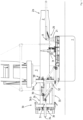
- FIG. 1 shows in cross section a vessel 1 according to the invention.
- he vessel is provided with a crane 3, an upending device 30 and an anti-swing device 20.
- the upending device 30 and the anti-swing device are mounted on the vessel at opposite sides thereof, such that a monopile can be received with one end in the upending device and with one end in the anti-swing device.
- Figure 1 depicts the crane 3 lowering a monopile 2 into a starting position, in which the monopile 2 is horizontally supported by the upending 30 device and monopile support 31.
- the monopile is supported with a top end 2a and a bottom end 2b received in respectively the anti-swing device 20 and the upending device 30.
- the upending device 30 is of a type known from the prior art. It is submitted that an anti-swing device according to the invention can be used with different types of upending devices.
- the pile upending device 30 comprises a support assembly 32 and a pile holder 33.
- the pile holder 33 is tiltable mounted on the deck mounted support assembly 32.
- the pile holder 30 is thus tiltable about a substantially horizontal tilt axis 39 relative to the support assembly 32 between a horizontal orientation, shown in Figure 1 , in which the monopile is horizontally supported, and a vertical orientation, in which the monopile is vertically supported, i.e. is upended.
- the upending device more in particular the pile holder 33, comprises a first ring 36a and a second ring 36b for engaging the monopile, a pile holder frame 31 supporting both rings, and a monopile foot end support 34 for engaging and supporting the bottom end 2b of the monopile.
- the second ring 36b is spaced from the first ring 36a, and at a vertical distance when the pile holder 33 is in the vertical orientation.
- both ring 36a and ring 36b comprise multiple pile engaging devices 39 distributed about the circumference of the lower ring 36a and the upper ring 36b respectively.
- the foot end support 34 is connected with the pile holder frame 31 such that it is vertically below the two rings 36a,36b, when the pile holder is in the vertical orientation.
- the pile foot end support 34 is configured to engage with a foot end 2b of a monopile in order to limit longitudinal movement of the pile, at least during upending of the pile.
- the both the ring 36a and the ring 36b each comprise a ring base mounted to the pile holder frame, and two movable, semi-circular jaws.
- Each jaw is movable between a closed position and an opened position.
- the ring 36a and the ring 36b each form a closed annulus.
- the ring 36a and the ring 36b each define a pile transfer opening.
- the jaws allow for the pile 2 to be moved in a lateral direction, i.e. in a direction substantially perpendicular to a longitudinal axis of the pile, through the pile transfer opening of the ring 36a and the ring 36b into a position in the pile holder.
- the monopile support 31 is mounted on a track 37.
- the track 37 extends along a monopile received in the upending device and the anti-swing device.
- the positon of the monopile support 31 can be adapted to fit monopiles of different lengths.
- Figures 13-16 show the anti-swing device 20 and the monopile support in different working positions for respectively engaging and supporting monopiles of different lengths.
- the crane 3, shown supporting the monopile 2 in figure 1 can be used for supporting a hoisting tool 10, see for example figure 2 and figure 3 .
- the hoisting tool 10 is adapted to be supported by the crane, and is adapted to be connected to an end 2a, i.e. the top end of the monopile 2 while being supported by the crane.
- the crane 3 can be used for lifting the top end 2a of the monopile 2, for upending the monopile while the bottom end 2b of the monopile is supported in the upending device 30, and for supporting the monopile 2 in a vertical position.
- the anti-swing device 20 is mounted to the vessel 1.
- the anti-swing device is adapted to be provided along the monopile and to extend beyond the monopile end, i.e. the top end 2a of the monopile 2.
- the anti-swing device 20 is furthermore adapted to engage the hoisting tool 10 in a proximate position thereof, for example shown in figure 2 and in figure 3 .
- the hoisting tool 10 is longitudinally spaced from the monopile, more in particular from the top end 2a of the monopile 2, and the radial contour of the hoisting tool 10 at least overlaps with a radial contour of the monopile top end.
- the hoisting tool In the proximate position, for example shown in figure 2 and figure 3 , the hoisting tool is supported by the crane, not shown in figure 2 and figure 3 , and is engaged by the anti-swing device.
- the anti-swing device thereby prevents swing of the suspended hoisting tool.
- the anti-swing device 20 is of a lightweight construction and is not equipped to support the weight of the hoisting tool 10.
- Figure 2 shows the end of the monopile 2, received in an anti-swing device 20 similar to the anti-swing device depicted in figure 1
- Figure 3 shows a top view of the configuration show in Figure 2 .
- a hoisting tool 10 supported by the crane 3, is shown in the proximate position, in which it is in engagement with the anti-swing device.
- the exemplary embodiment of the anti-swing device 20 comprises a static portion 22, 22' mounted to the vessel and a telescopic portion 23, 23' engaging the hoisting tool 10, and an actuator allowing movement of the telescopic portion 23, 23' engaging the hoisting tool 10 with respect to the static portion 22, 22'of the anti-swing device.
- the anti-swing device 20 comprises a base 21 is mounted to the vessel and two pivot arms 22, 23; 22', 23', which in the exemplary embodiment shown, are pivotable about a horizontal pivot axis A.
- the two pivot arms of the anti-swing device 20 are parallel arms 22, 23; 22', 23' that define between them a space S for the monopile 2 and for the hoisting tool 10.
- the two parallel arms 22, 23; 22', 23' are telescopic arms comprising a static portion mounted to the vessel and a telescopic portion engaging the hoisting tool 10.
- the anti-swing device 20 comprises movable monopile contact points 24 and an actuator 24a allowing movement of the monopile contact points from a proximate position into a connected position longitudinally aligned with the monopile end, prior to connection of the hoisting tool, to prevent movements of the monopile, e.g. vessel induced movements.
- the pivot arms of the anti-swing device 20 are pivotable during the hoisting process to remain engaged with the monopile, e.g. while the monopile includes an angle of 0-15° with the horizontal.
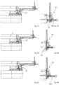
- Figures 4A-10A show consecutive steps of a method of upending according to the invention, while Figures 4B-10B show a partial close up of the steps shown in figs. 4A-10A respectively.
- the method comprises upending a monopile 2 of an offshore wind turbine from a horizontal position, shown in Figure 5A , on a vessel 1 to an upended vertical position of said monopile 2, shown in Figure 11 .
- FIGS. 4A-10B show part of a monopile, of which the upper end is received in the anti-swing device 20 according to the invention. It is submitted that during the upending process, a bottom end of the monopile 2 is supported in a pile upending device, for example as shown in Figure 1 .
- the vessel 1, depicted in the figures 4a-12 has a configuration similar to the vessel 1 depicted in Figure 1 .
- the vessel 1 comprises a crane adapted to support a hoisting tool 10, which hoisting tool 10 is adapted to be connected to an end of the monopile 2 while being supported by the crane.
- the vessel further comprises an anti-swing device 20 mounted to the vessel 1, and adapted to prevent swing of the suspended hoisting tool.
- the vessel also comprises a pile upending device. It is submitted that the pile upending device and the crane for upending the monopile 2 are not depicted in Figures 4a-Fig 16 .
- the anti-swing device 20 comprises a comprises a base 21 that is mounted to the vessel 1, and two pivot arms of which one pivot arm 22', 23' is visible.
- the anti-swing device is furthermore provided with two movable monopile contact points 24 and an actuator 24a, similar to the configuration shown in figure 2 and Figure 3 .
- the actuators 24a one for each monopile contact point, enables movement of the monopile contact points from a proximate position into a connected position. It is submitted that the pivot arm 22', 23' is depicted in partial see-through. Therefore, one of the monopile contact points 24 and one of the actuators 24a are depicted in Figures 4A-10B .
- Figure 4a shows the monopile 2 being lowered by the crane onto the monopile support 31 and into the space S defined between the two pivot arms.
- Figures 5A- 9B the monopile 2 is received in the space S.
- the telescopic arms 22', 23' are longitudinally aligned with the monopile end.
- Figure 5a shows the monopile 2 being supported in a horizontal position by the vessel 1, with the ends of the monopile extending beyond the vessel 1.
- the partial see-though in Figure 5B shows that the monopile contact points 24, in the embodiment shown each supported by an actuators 24a in the form of telescopic actuators, for example hydraulic cylinders or electric spindles, for engaging the monopile 2, do not yet engage the monopile.
- the actuators 24a one for each monopile contact point, enable movement of the monopile contact points 24 from a proximate position, depicted in Figure 5a and figure 5B , into a connected position, depicted in Figure 6a and figure 6B .
- the method furthermore comprises moving, by means of the crane, the hoisting tool 10 into a proximate position thereof, shown in figure 7A and figure 7B .
- the hoisting tool 10 When in the proximal position, the hoisting tool 10 is longitudinally spaced from the monopile end 2a.
- the anti-swing device by engaging the hoisting tool 10 in the proximate position, aids in positioning the hoisting tool with a radial contour of the hoisting tool at least overlapping with the radial contour of the monopile end. It is submitted that in the proximate position the hoisting tool is supported by the crane, and that the anti-swing device is of a lightweight construction not equipped to support the weight of the hoisting tool. Furthermore, engaging the hoisting tool 10 by the anti-swing device 20, in the proximate position of the hoisting tool, prevents swing of the suspended hoisting tool.
- the suspended hoisting tool 10 is moved from the proximate position into a connection position, shown in Figure 8a and Figure 8B .
- the hoisting tool 10 is longitudinally aligned with the monopile end.
- the hoisting tool maintains being supported by the crane and engaged by the anti-swing device while it is moved from the proximate position into a connection position.
- the hoisting tool 10 When in the connection position, the hoisting tool 10 is connected to the monopile end 2a, and the monopile 2, more in particular the top end 2a of the monopile 2, is suspend via the hoisting tool from the crane.
- Figures 10a and 10b show the top end 2A of the monopile being suspended by the hoisting tool 10.
- this condition of the telescopic actuators 24a allows for the contact points 24a to keep in engagement with the top end 2a of the pile 2, while the pile is being lifted along a first part of an upending trajectory.
- FIG 10a and Figure 10B the monopile is upended by the crane lifting the top end 2a of the monopile 2, while the bottom end of the monopile 2 is pivotable supported by the upending device. The monopile is thus pivoted about the pivot axis defined by the upending device. Therefore, the telescopic actuators 24a are retracted while the contact points 34 move with, and engage, the top end of the monopile 2.
- the anti-swing device preferably is configured to enable the contact points 24 to remain in contact with the top end of the monopile until the monopile is at least upended over angle of 5 degrees, more preferably of at least 10 degrees, for example 15 degrees.
- the telescopic arms 22', 23' of the anti-swing device can be extended during the lifting of the monopile 2 to allow for the contact points to restrain the monopile, i.e. to prevent or at least reduce axial movement of the monopile.
- the contact points disengage the top end of the monopile.
- the hoisting tool 10 is disengaged from the anti-swing device.
- the monopile is subsequently upended by means of the crane into a vertical position, shown in Figure 11 .
- Figure 12 shows the vessel 1 in cross section, with the anti-swing device in a parking position.
- the pivotable supported telescopic arms 22', 23' are in an upright position.
- This configuration provides the anti-swing device with a minimal footprint on the deck of the vessel, when the anti-swing device is not in use.
- the pivot arms are retracted within the contour of the vessel, which is for example beneficial when the vessel is docking in a harbour, or is in close proximity of other ships or objects.
- Figure 17 and figure 18 each show an axial view in cross section of an anti-swing device 20 and a hoisting tool 10.
- the parallel arms 22, 23; 22', 23' and the actuators 24 are depicted in cross section.
- Figure 17 shows the hoisting tool 10 while being lowered towards the anti-swing device 20.
- the hoisting tool is provided with guide bumpers 38 configured for guiding a lower part of the hoisting tool 10 between the parallel arms 22, 23; 22', 23' of the anti-swing device, more in particular between the parallel actuators 24 of the anti-swing device.
- Figure 18 shows the hoisting tool 10 engaging the anti-swing device, more in particular the actuators 24 of the anti-swing device 10, such that the hoisting tool is aligned with the top end of the monopile and can be coupled with a top end of a monopile.
Landscapes
- Engineering & Computer Science (AREA)
- General Engineering & Computer Science (AREA)
- Life Sciences & Earth Sciences (AREA)
- Sustainable Energy (AREA)
- Sustainable Development (AREA)
- Structural Engineering (AREA)
- Chemical & Material Sciences (AREA)
- Combustion & Propulsion (AREA)
- Mechanical Engineering (AREA)
- General Life Sciences & Earth Sciences (AREA)
- Mining & Mineral Resources (AREA)
- Paleontology (AREA)
- Civil Engineering (AREA)
- Jib Cranes (AREA)
- Load-Engaging Elements For Cranes (AREA)
Claims (12)
- Verfahren zum Aufrichten eines Monopiles einer Offshore-Windenergieanlage von einer horizontalen Position auf einem Schiff in eine aufgerichtete vertikale Position des Monopiles, wobei der Monopile in der horizontalen Position vom Schiff getragen wird, wobei sich dessen Enden über das Schiff hinaus erstrecken; wobei das Schiff einen Kran (3) umfasst, der dazu eingerichtet ist, ein Hebewerkzeug (10) zu tragen,wobei das Hebewerkzeug dazu eingerichtet ist, mit einem Ende des Monopiles verbunden zu sein, während es vom Kran getragen wird; wobei das Schiff ferner eine am Schiff montierte Anti-Schwenk-Vorrichtung (20) umfasst, die dazu eingerichtet ist, das Verschwenken des hängenden Hebewerkzeugs zu verhindern;wobei das Verfahren die folgenden Schritte umfasst:a) Vorsehen der Anti-Schwenk-Vorrichtung entlang des Monopiles und über das Monopile-Ende hinaus erstreckend;b) Bewegen des Hebewerkzeugs mittels des Krans in eine proximale Position, in welcher das Hebewerkzeug von dem Monopile-Ende in Längsrichtung beabstandet ist und in welcher die radiale Kontur des Hebewerkzeugs die radiale Kontur des Monopile-Endes zumindest überlagert, wobei das Hebewerkzeug in der proximalen Position vom Kran getragen wird;c) Eingreifen der Anti-Schwenk-Vorrichtung in das Hebewerkzeug in der proximalen Position des Hebewerkzeugs, wobei die Anti-Schwenk-Vorrichtung dadurch das Verschwenken des hängenden Hebewerkzeugs verhindert;d) Bewegen des hängenden Hebewerkzeugs von der proximalen Position in eine Verbindungsposition, die in Längsrichtung mit dem Monopile-Ende ausgerichtet ist, während das Hebewerkzeug weiterhin vom Kran getragen und von der Anti-Schwenk-Vorrichtung eingegriffen wird;e) Verbinden des Hebewerkzeugs mit dem Monopile-Ende und Aufhängen des Monopile-Endes über das Hebewerkzeug am Kran,f) Lösen des Hebewerkzeugs von der Anti-Schwenk-Vorrichtung,g) Anheben des mit dem Hebewerkzeug verbundenen Monopile-Endes mittels des Krans.
- Verfahren nach Anspruch 1, wobei die Anti-Schwenk-Vorrichtung einen am Schiff montierten statischen Abschnitt und einen in das Hebewerkzeug eingreifenden Teleskopabschnitt und ein Stellglied, das die Bewegung des in das hängende Hebewerkzeug eingegriffenen Teleskopabschnitts in Bezug zum statischen Abschnitt der Anti-Schwenk-Vorrichtung von der proximalen Position in die mit dem Monopile-Ende in Längsrichtung ausgerichtete Verbindungsposition zulässt, umfasst.
- Verfahren nach Anspruch 1 oder 2, wobei die Anti-Schwenk-Vorrichtung bewegliche Monopile-Kontaktpunkte und ein Stellglied, das die Bewegung der Monopile-Kontaktpunkte zulässt, umfasst und wobei das Stellglied nach Schritt a) die Monopile-Kontaktpunkte von einer proximalen Position in eine mit dem Monopile-Ende in Längsrichtung ausgerichtete Verbindungsposition bewegt, um Bewegungen des Monopiles, z. B. vom Schiff eingeleitete Bewegungen, zu verhindern.
- Verfahren nach einem der vorstehenden Ansprüche, wobei die Anti-Schwenk-Vorrichtung einen am Schiff montierten Sockel und einen oder mehrere Schwenkarme, die um eine horizontale Schwenkachse schwenkbar sind, umfasst, wodurch zugelassen wird, dass die Anti-Schwenk-Vorrichtung beim Start des Hebevorgangs in den Monopile eingegriffen bleibt, z. B. während der Monopile einen Winkel von 0-15° zur Horizontalen aufweist.
- Schiff (1) zum Aufrichten eines Monopiles (2) einer Offshore-Windenergieanlage von einer horizontalen Position auf dem Schiff in eine aufgerichtete vertikale Position des Monopiles, wobei das Schiff mit Folgendem versehen ist:- dem Monopile, der in der horizontalen Position vom Schiff getragen wird, wobei sich dessen Enden (2a, 2b) über das Schiff hinaus erstrecken;- einem Kran (3);- einem Hebewerkzeug (10), das dazu eingerichtet ist, vom Kran getragen zu werden, und dazu eingerichtet ist, mit einem Ende (2a) des Monopiles verbunden zu sein, während es vom Kran getragen wird;- einer Anti-Schwenk-Vorrichtung (20), die am Schiff montiert und dazu eingerichtet ist, entlang des Monopiles vorgesehen zu sein und sich über das Monopile-Ende hinaus zu erstrecken; wobei die Anti-Schwenk-Vorrichtung dazu eingerichtet ist, in das Hebewerkzeug in einer proximalen Position, in welcher das Hebewerkzeug in Längsrichtung vom Monopile-Ende beabstandet ist und in welcher die radiale Kontur des Hebewerkzeugs die radiale Kontur des Monopile-Endes zumindest überlagert, einzugreifen, wobei das Hebewerkzeug in der proximalen Position vom Kran getragen wird, wobei die Anti-Schwenk-Vorrichtung dabei das Verschwenken des hängenden Hebewerkzeugs verhindert; wobei die Anti-Schwenk-Vorrichtung aus einer Leichtbaukonstruktion besteht und nicht dazu ausgestattet ist, das Gewicht des Hebewerkzeugs zu tragen.
- Schiff nach Anspruch 5, wobei die Anti-Schwenk-Vorrichtung (20) einen am Schiff montierten statischen Abschnitt (22, 22') und einen in das Hebewerkzeug (10) eingreifenden Teleskopabschnitt (23, 23') und ein Stellglied, das die Bewegung des in das Hebewerkzeug eingegriffenen Teleskopabschnitts in Bezug zum statischen Abschnitt der Anti-Schwenk-Vorrichtung zulässt, umfasst.
- Schiff nach Anspruch 5 oder 6, wobei die Anti-Schwenk-Vorrichtung zwei parallele Arme (22, 23; 22', 23') umfasst, die dazwischen einen Zwischenraum (S) für den Monopile (2) und für das Hebewerkzeug (10) definieren, z. B. wobei die Arme Teleskoparme sind, die einen am Schiff montierten statischen Abschnitt und einen in das Hebewerkzeug eingreifenden Teleskopabschnitt umfassen.
- Schiff nach einem der Ansprüche 5-7, wobei die Anti-Schwenk-Vorrichtung bewegliche Monopile-Kontaktpunkte (24) und ein Stellglied (24a), das die Bewegung der Monopile-Kontaktpunkte von einer proximalen Position in eine mit dem Monopile-Ende in Längsrichtung ausgerichtete verbundene Position vor der Verbindung mit dem Hebewerkzeug zulässt, um die Bewegung des Monopiles, z. B. vom Schiff eingeleitete Bewegungen, zu verhindern, umfasst.
- Schiff nach einem der Ansprüche 5-8, wobei die Anti-Schwenk-Vorrichtung einen am Schiff montierten Sockel (21) und einen oder mehrere Schwenkarme (22, 23; 22', 23'), die um eine horizontale Schwenkachse (A) schwenkbar sind, umfasst.
- Schiff nach Anspruch 8 und 9, wobei der eine oder die mehreren Schwenkarme der Anti-Schwenk-Vorrichtung während des Hebevorgangs schwenkbar sind, um in den Monopile eingegriffen zu bleiben, z. B. während der Monopile einen Winkel von 0-15° zur Horizontalen aufweist.
- Anti-Schwenk-Vorrichtung nach Anspruch 12, die auf einem Schiff montiert ist und mit einem Hebewerkzeug kombiniert ist, das dazu eingerichtet ist, von einem Kran getragen zu werden, und dazu eingerichtet ist, mit einem Ende des Monopiles verbunden zu sein, während es vom Kran getragen wird, um den Monopile von einer horizontalen Position in eine aufgerichtete vertikale Position aufzurichten.
- Anti-Schwenk-Vorrichtung (20), die dazu eingerichtet ist, auf einem Schiff zum Aufrichten eines Monopiles (2) einer Offshore-Windenergieanlage von einer horizontalen Position auf dem Schiff in eine aufgerichtete vertikale Position des Monopiles nach einem der Verfahrensansprüche 1-4 montiert zu sein, wobei das Schiff mit einem Kran versehen ist; gekennzeichnet durch die folgenden Merkmale:
die Anti-Schwenk-Vorrichtung ist dazu eingerichtet, entlang des Monopiles vorgesehen zu sein und sich über das Monopile-Ende hinaus zu erstrecken; wobei die Anti-Schwenk-Vorrichtung dazu eingerichtet ist, in ein Hebewerkzeug in einer proximalen Position, in welcher das Hebewerkzeug in Längsrichtung vom Monopile-Ende beabstandet ist und in welcher die radiale Kontur des Hebewerkzeugs die radiale Kontur des Monopile-Endes zumindest überlagert, einzugreifen, wobei das Hebewerkzeug in der proximalen Position vom Kran getragen wird, wobei die Anti-Schwenk-Vorrichtung dabei das Verschwenken des hängenden Hebewerkzeugs verhindert; wobei die Anti-Schwenk-Vorrichtung aus einer Leichtbaukonstruktion besteht und nicht dazu ausgestattet ist, das Gewicht des Hebewerkzeugs zu tragen.
Applications Claiming Priority (2)
| Application Number | Priority Date | Filing Date | Title |
|---|---|---|---|
| NL2026846 | 2020-11-06 | ||
| PCT/EP2021/080543 WO2022096523A1 (en) | 2020-11-06 | 2021-11-03 | Vessel and method for upending a monopile of an offshore wind turbine |
Publications (2)
| Publication Number | Publication Date |
|---|---|
| EP4240964A1 EP4240964A1 (de) | 2023-09-13 |
| EP4240964B1 true EP4240964B1 (de) | 2025-03-19 |
Family
ID=75340201
Family Applications (1)
| Application Number | Title | Priority Date | Filing Date |
|---|---|---|---|
| EP21802715.9A Active EP4240964B1 (de) | 2020-11-06 | 2021-11-03 | Schiff und verfahren zum aufrichten eines einpfahls einer offshore-windturbine |
Country Status (3)
| Country | Link |
|---|---|
| EP (1) | EP4240964B1 (de) |
| DK (1) | DK4240964T3 (de) |
| WO (1) | WO2022096523A1 (de) |
Families Citing this family (2)
| Publication number | Priority date | Publication date | Assignee | Title |
|---|---|---|---|---|
| NL2034539B1 (en) | 2023-04-11 | 2024-10-15 | Delta Laboratories Holding B V | Method and System for Compensating Motion of a Suspended Object |
| GB2636875A (en) | 2023-12-29 | 2025-07-02 | Seaway 7 Eng B V | Upending elongate structures offshore |
Family Cites Families (9)
| Publication number | Priority date | Publication date | Assignee | Title |
|---|---|---|---|---|
| DE202009006507U1 (de) | 2009-04-30 | 2009-08-06 | Bard Engineering Gmbh | Führungsgestell zum vertikalen Führen von mindestens einem Fundamentpfahl beim Errichten eines Fundaments einer Offshore-Windenergieanlage und Stapel-, Aufricht- und Absenkvorrichtung zum Errichten eines Fundaments einer Offshore-Windenergieanlage |
| NL2014049B1 (en) | 2014-12-23 | 2016-10-12 | Ihc Holland Ie Bv | Pile upending system. |
| WO2018139918A1 (en) | 2017-01-25 | 2018-08-02 | Itrec B.V. | A method and tool for installation of an offshore wind turbine |
| DK3517479T3 (da) * | 2018-01-30 | 2022-09-12 | Deme Offshore Be Nv | Anordning og fremgangsmåde til placering af et stort, smalt objekt med en langsgående retning ned i en undervandsbund |
| EP3762550B1 (de) * | 2018-03-06 | 2022-08-10 | Itrec B.V. | Verstellbares pfahlhaltesystem, behälter und pfahlinstallationsverfahren |
| NL2021025B1 (en) | 2018-05-31 | 2019-12-10 | Temporary Works Design Eng B V | Monopile fastening system |
| US10308327B1 (en) * | 2018-07-10 | 2019-06-04 | GeoSea N.V. | Device and method for lifting an object from a deck of a vessel subject to movements |
| BE1026067B1 (nl) | 2018-07-26 | 2019-09-26 | DEME Offshore Holding N.V. | Koppeltuig voor verbinding met een uiteinde van een buisvormig element ter oprichting van het element |
| BE1026068B9 (nl) | 2018-07-26 | 2019-10-02 | Deme Offshore Holding N V | Inrichting en werkwijze voor het vanaf een steunvlak aan een uiteinde oprichten van een buisvormig element met een lengterichting |
-
2021
- 2021-11-03 EP EP21802715.9A patent/EP4240964B1/de active Active
- 2021-11-03 WO PCT/EP2021/080543 patent/WO2022096523A1/en not_active Ceased
- 2021-11-03 DK DK21802715.9T patent/DK4240964T3/da active
Also Published As
| Publication number | Publication date |
|---|---|
| EP4240964A1 (de) | 2023-09-13 |
| DK4240964T3 (da) | 2025-06-30 |
| WO2022096523A1 (en) | 2022-05-12 |
Similar Documents
| Publication | Publication Date | Title |
|---|---|---|
| EP3810926B1 (de) | Verfahren zur installation einer windturbine und fahrzeug | |
| EP4034712B1 (de) | System und verfahren zum aufrichten und halten von stapeln | |
| EP3517479B1 (de) | Vorrichtung und verfahren zur platzierung eines grossen, schmalen objekts mit einer längsrichtung in einen unterwasserboden | |
| WO2019245366A1 (en) | Wind turbine installation method | |
| EP2307712B1 (de) | Verfahren zum errichten einer windturbine an einem offshore-standort und schiff zum errichten einer windturbine an einem offshore-standort | |
| EP4107108B1 (de) | Freihändiges monopile-hebewerkzeug | |
| EP3898402B1 (de) | Schiff und vorrichtung zum hochkantstellen eines länglichen elementes von einem deck des schiffes mittels einer hebevorrichtung | |
| US20240208779A1 (en) | Installation vessel, lifting device, pile gripper, control unit and method | |
| EP4240964B1 (de) | Schiff und verfahren zum aufrichten eines einpfahls einer offshore-windturbine | |
| US20240369039A1 (en) | Wind turbine blade installation apparatus and method of installing a wind turbine blade | |
| CN117561210A (zh) | 安装船舶、提升装置、桩柱夹持器、控制单元和方法 |
Legal Events
| Date | Code | Title | Description |
|---|---|---|---|
| STAA | Information on the status of an ep patent application or granted ep patent |
Free format text: STATUS: UNKNOWN |
|
| STAA | Information on the status of an ep patent application or granted ep patent |
Free format text: STATUS: THE INTERNATIONAL PUBLICATION HAS BEEN MADE |
|
| PUAI | Public reference made under article 153(3) epc to a published international application that has entered the european phase |
Free format text: ORIGINAL CODE: 0009012 |
|
| STAA | Information on the status of an ep patent application or granted ep patent |
Free format text: STATUS: REQUEST FOR EXAMINATION WAS MADE |
|
| 17P | Request for examination filed |
Effective date: 20230601 |
|
| AK | Designated contracting states |
Kind code of ref document: A1 Designated state(s): AL AT BE BG CH CY CZ DE DK EE ES FI FR GB GR HR HU IE IS IT LI LT LU LV MC MK MT NL NO PL PT RO RS SE SI SK SM TR |
|
| TPAC | Observations filed by third parties |
Free format text: ORIGINAL CODE: EPIDOSNTIPA |
|
| DAV | Request for validation of the european patent (deleted) | ||
| DAX | Request for extension of the european patent (deleted) | ||
| REG | Reference to a national code |
Ref country code: DE Ref legal event code: R079 Free format text: PREVIOUS MAIN CLASS: F03D0013100000 Ipc: B63B0035000000 Ref country code: DE Ref legal event code: R079 Ref document number: 602021027875 Country of ref document: DE Free format text: PREVIOUS MAIN CLASS: F03D0013100000 Ipc: B63B0035000000 |
|
| GRAP | Despatch of communication of intention to grant a patent |
Free format text: ORIGINAL CODE: EPIDOSNIGR1 |
|
| RIC1 | Information provided on ipc code assigned before grant |
Ipc: E02D 15/08 20060101ALI20240904BHEP Ipc: B63B 35/00 20200101AFI20240904BHEP |
|
| STAA | Information on the status of an ep patent application or granted ep patent |
Free format text: STATUS: GRANT OF PATENT IS INTENDED |
|
| INTG | Intention to grant announced |
Effective date: 20241010 |
|
| GRAS | Grant fee paid |
Free format text: ORIGINAL CODE: EPIDOSNIGR3 |
|
| GRAA | (expected) grant |
Free format text: ORIGINAL CODE: 0009210 |
|
| STAA | Information on the status of an ep patent application or granted ep patent |
Free format text: STATUS: THE PATENT HAS BEEN GRANTED |
|
| AK | Designated contracting states |
Kind code of ref document: B1 Designated state(s): AL AT BE BG CH CY CZ DE DK EE ES FI FR GB GR HR HU IE IS IT LI LT LU LV MC MK MT NL NO PL PT RO RS SE SI SK SM TR |
|
| REG | Reference to a national code |
Ref country code: GB Ref legal event code: FG4D |
|
| REG | Reference to a national code |
Ref country code: CH Ref legal event code: EP |
|
| REG | Reference to a national code |
Ref country code: DE Ref legal event code: R096 Ref document number: 602021027875 Country of ref document: DE |
|
| REG | Reference to a national code |
Ref country code: IE Ref legal event code: FG4D |
|
| REG | Reference to a national code |
Ref country code: DK Ref legal event code: T3 Effective date: 20250625 |
|
| PG25 | Lapsed in a contracting state [announced via postgrant information from national office to epo] |
Ref country code: RS Free format text: LAPSE BECAUSE OF FAILURE TO SUBMIT A TRANSLATION OF THE DESCRIPTION OR TO PAY THE FEE WITHIN THE PRESCRIBED TIME-LIMIT Effective date: 20250619 |
|
| PG25 | Lapsed in a contracting state [announced via postgrant information from national office to epo] |
Ref country code: FI Free format text: LAPSE BECAUSE OF FAILURE TO SUBMIT A TRANSLATION OF THE DESCRIPTION OR TO PAY THE FEE WITHIN THE PRESCRIBED TIME-LIMIT Effective date: 20250319 |
|
| REG | Reference to a national code |
Ref country code: NL Ref legal event code: FP |
|
| REG | Reference to a national code |
Ref country code: LT Ref legal event code: MG9D |
|
| PG25 | Lapsed in a contracting state [announced via postgrant information from national office to epo] |
Ref country code: NO Free format text: LAPSE BECAUSE OF FAILURE TO SUBMIT A TRANSLATION OF THE DESCRIPTION OR TO PAY THE FEE WITHIN THE PRESCRIBED TIME-LIMIT Effective date: 20250619 |
|
| PG25 | Lapsed in a contracting state [announced via postgrant information from national office to epo] |
Ref country code: HR Free format text: LAPSE BECAUSE OF FAILURE TO SUBMIT A TRANSLATION OF THE DESCRIPTION OR TO PAY THE FEE WITHIN THE PRESCRIBED TIME-LIMIT Effective date: 20250319 |
|
| PG25 | Lapsed in a contracting state [announced via postgrant information from national office to epo] |
Ref country code: LV Free format text: LAPSE BECAUSE OF FAILURE TO SUBMIT A TRANSLATION OF THE DESCRIPTION OR TO PAY THE FEE WITHIN THE PRESCRIBED TIME-LIMIT Effective date: 20250319 |
|
| PG25 | Lapsed in a contracting state [announced via postgrant information from national office to epo] |
Ref country code: GR Free format text: LAPSE BECAUSE OF FAILURE TO SUBMIT A TRANSLATION OF THE DESCRIPTION OR TO PAY THE FEE WITHIN THE PRESCRIBED TIME-LIMIT Effective date: 20250620 Ref country code: BG Free format text: LAPSE BECAUSE OF FAILURE TO SUBMIT A TRANSLATION OF THE DESCRIPTION OR TO PAY THE FEE WITHIN THE PRESCRIBED TIME-LIMIT Effective date: 20250319 |
|
| REG | Reference to a national code |
Ref country code: AT Ref legal event code: MK05 Ref document number: 1776763 Country of ref document: AT Kind code of ref document: T Effective date: 20250319 |
|
| PG25 | Lapsed in a contracting state [announced via postgrant information from national office to epo] |
Ref country code: SE Free format text: LAPSE BECAUSE OF FAILURE TO SUBMIT A TRANSLATION OF THE DESCRIPTION OR TO PAY THE FEE WITHIN THE PRESCRIBED TIME-LIMIT Effective date: 20250319 |
|
| PG25 | Lapsed in a contracting state [announced via postgrant information from national office to epo] |
Ref country code: SM Free format text: LAPSE BECAUSE OF FAILURE TO SUBMIT A TRANSLATION OF THE DESCRIPTION OR TO PAY THE FEE WITHIN THE PRESCRIBED TIME-LIMIT Effective date: 20250319 |
|
| PG25 | Lapsed in a contracting state [announced via postgrant information from national office to epo] |
Ref country code: ES Free format text: LAPSE BECAUSE OF FAILURE TO SUBMIT A TRANSLATION OF THE DESCRIPTION OR TO PAY THE FEE WITHIN THE PRESCRIBED TIME-LIMIT Effective date: 20250319 Ref country code: PT Free format text: LAPSE BECAUSE OF FAILURE TO SUBMIT A TRANSLATION OF THE DESCRIPTION OR TO PAY THE FEE WITHIN THE PRESCRIBED TIME-LIMIT Effective date: 20250721 |
|
| PG25 | Lapsed in a contracting state [announced via postgrant information from national office to epo] |
Ref country code: IT Free format text: LAPSE BECAUSE OF FAILURE TO SUBMIT A TRANSLATION OF THE DESCRIPTION OR TO PAY THE FEE WITHIN THE PRESCRIBED TIME-LIMIT Effective date: 20250319 Ref country code: PL Free format text: LAPSE BECAUSE OF FAILURE TO SUBMIT A TRANSLATION OF THE DESCRIPTION OR TO PAY THE FEE WITHIN THE PRESCRIBED TIME-LIMIT Effective date: 20250319 |
|
| PG25 | Lapsed in a contracting state [announced via postgrant information from national office to epo] |
Ref country code: AT Free format text: LAPSE BECAUSE OF FAILURE TO SUBMIT A TRANSLATION OF THE DESCRIPTION OR TO PAY THE FEE WITHIN THE PRESCRIBED TIME-LIMIT Effective date: 20250319 |
|
| PG25 | Lapsed in a contracting state [announced via postgrant information from national office to epo] |
Ref country code: EE Free format text: LAPSE BECAUSE OF FAILURE TO SUBMIT A TRANSLATION OF THE DESCRIPTION OR TO PAY THE FEE WITHIN THE PRESCRIBED TIME-LIMIT Effective date: 20250319 Ref country code: CZ Free format text: LAPSE BECAUSE OF FAILURE TO SUBMIT A TRANSLATION OF THE DESCRIPTION OR TO PAY THE FEE WITHIN THE PRESCRIBED TIME-LIMIT Effective date: 20250319 |
|
| PG25 | Lapsed in a contracting state [announced via postgrant information from national office to epo] |
Ref country code: RO Free format text: LAPSE BECAUSE OF FAILURE TO SUBMIT A TRANSLATION OF THE DESCRIPTION OR TO PAY THE FEE WITHIN THE PRESCRIBED TIME-LIMIT Effective date: 20250319 |
|
| PG25 | Lapsed in a contracting state [announced via postgrant information from national office to epo] |
Ref country code: SK Free format text: LAPSE BECAUSE OF FAILURE TO SUBMIT A TRANSLATION OF THE DESCRIPTION OR TO PAY THE FEE WITHIN THE PRESCRIBED TIME-LIMIT Effective date: 20250319 |
|
| PG25 | Lapsed in a contracting state [announced via postgrant information from national office to epo] |
Ref country code: IS Free format text: LAPSE BECAUSE OF FAILURE TO SUBMIT A TRANSLATION OF THE DESCRIPTION OR TO PAY THE FEE WITHIN THE PRESCRIBED TIME-LIMIT Effective date: 20250719 |
|
| PGFP | Annual fee paid to national office [announced via postgrant information from national office to epo] |
Ref country code: NL Payment date: 20251124 Year of fee payment: 5 |
|
| REG | Reference to a national code |
Ref country code: DE Ref legal event code: R097 Ref document number: 602021027875 Country of ref document: DE |
|
| PGFP | Annual fee paid to national office [announced via postgrant information from national office to epo] |
Ref country code: DE Payment date: 20251118 Year of fee payment: 5 |
|
| PGFP | Annual fee paid to national office [announced via postgrant information from national office to epo] |
Ref country code: GB Payment date: 20251120 Year of fee payment: 5 |
|
| PGFP | Annual fee paid to national office [announced via postgrant information from national office to epo] |
Ref country code: DK Payment date: 20251119 Year of fee payment: 5 |
|
| PGFP | Annual fee paid to national office [announced via postgrant information from national office to epo] |
Ref country code: BE Payment date: 20251124 Year of fee payment: 5 |
|
| PLBE | No opposition filed within time limit |
Free format text: ORIGINAL CODE: 0009261 |
|
| STAA | Information on the status of an ep patent application or granted ep patent |
Free format text: STATUS: NO OPPOSITION FILED WITHIN TIME LIMIT |
|
| REG | Reference to a national code |
Ref country code: CH Ref legal event code: L10 Free format text: ST27 STATUS EVENT CODE: U-0-0-L10-L00 (AS PROVIDED BY THE NATIONAL OFFICE) Effective date: 20260128 |