EP4034492B1 - Systeme und verfahren zur herstellung von geschlossenen mikrofluidischen vorrichtungen - Google Patents
Systeme und verfahren zur herstellung von geschlossenen mikrofluidischen vorrichtungen Download PDFInfo
- Publication number
- EP4034492B1 EP4034492B1 EP20786679.9A EP20786679A EP4034492B1 EP 4034492 B1 EP4034492 B1 EP 4034492B1 EP 20786679 A EP20786679 A EP 20786679A EP 4034492 B1 EP4034492 B1 EP 4034492B1
- Authority
- EP
- European Patent Office
- Prior art keywords
- channel
- channel layer
- cap component
- membrane
- well plate
- Prior art date
- Legal status (The legal status is an assumption and is not a legal conclusion. Google has not performed a legal analysis and makes no representation as to the accuracy of the status listed.)
- Active
Links
Images


Classifications
-
- B—PERFORMING OPERATIONS; TRANSPORTING
- B81—MICROSTRUCTURAL TECHNOLOGY
- B81C—PROCESSES OR APPARATUS SPECIALLY ADAPTED FOR THE MANUFACTURE OR TREATMENT OF MICROSTRUCTURAL DEVICES OR SYSTEMS
- B81C3/00—Assembling of devices or systems from individually processed components
- B81C3/008—Aspects related to assembling from individually processed components, not covered by groups B81C3/001 - B81C3/002
-
- B—PERFORMING OPERATIONS; TRANSPORTING
- B01—PHYSICAL OR CHEMICAL PROCESSES OR APPARATUS IN GENERAL
- B01L—CHEMICAL OR PHYSICAL LABORATORY APPARATUS FOR GENERAL USE
- B01L3/00—Containers or dishes for laboratory use, e.g. laboratory glassware; Droppers
- B01L3/50—Containers for the purpose of retaining a material to be analysed, e.g. test tubes
- B01L3/502—Containers for the purpose of retaining a material to be analysed, e.g. test tubes with fluid transport, e.g. in multi-compartment structures
- B01L3/5027—Containers for the purpose of retaining a material to be analysed, e.g. test tubes with fluid transport, e.g. in multi-compartment structures by integrated microfluidic structures, i.e. dimensions of channels and chambers are such that surface tension forces are important, e.g. lab-on-a-chip
- B01L3/502707—Containers for the purpose of retaining a material to be analysed, e.g. test tubes with fluid transport, e.g. in multi-compartment structures by integrated microfluidic structures, i.e. dimensions of channels and chambers are such that surface tension forces are important, e.g. lab-on-a-chip characterised by the manufacture of the container or its components
-
- B—PERFORMING OPERATIONS; TRANSPORTING
- B01—PHYSICAL OR CHEMICAL PROCESSES OR APPARATUS IN GENERAL
- B01L—CHEMICAL OR PHYSICAL LABORATORY APPARATUS FOR GENERAL USE
- B01L3/00—Containers or dishes for laboratory use, e.g. laboratory glassware; Droppers
- B01L3/50—Containers for the purpose of retaining a material to be analysed, e.g. test tubes
- B01L3/502—Containers for the purpose of retaining a material to be analysed, e.g. test tubes with fluid transport, e.g. in multi-compartment structures
- B01L3/5025—Containers for the purpose of retaining a material to be analysed, e.g. test tubes with fluid transport, e.g. in multi-compartment structures for parallel transport of multiple samples
- B01L3/50255—Multi-well filtration
-
- B—PERFORMING OPERATIONS; TRANSPORTING
- B29—WORKING OF PLASTICS; WORKING OF SUBSTANCES IN A PLASTIC STATE IN GENERAL
- B29C—SHAPING OR JOINING OF PLASTICS; SHAPING OF MATERIAL IN A PLASTIC STATE, NOT OTHERWISE PROVIDED FOR; AFTER-TREATMENT OF THE SHAPED PRODUCTS, e.g. REPAIRING
- B29C45/00—Injection moulding, i.e. forcing the required volume of moulding material through a nozzle into a closed mould; Apparatus therefor
- B29C45/16—Making multilayered or multicoloured articles
- B29C45/1671—Making multilayered or multicoloured articles with an insert
-
- B—PERFORMING OPERATIONS; TRANSPORTING
- B81—MICROSTRUCTURAL TECHNOLOGY
- B81C—PROCESSES OR APPARATUS SPECIALLY ADAPTED FOR THE MANUFACTURE OR TREATMENT OF MICROSTRUCTURAL DEVICES OR SYSTEMS
- B81C1/00—Manufacture or treatment of devices or systems in or on a substrate
- B81C1/00015—Manufacture or treatment of devices or systems in or on a substrate for manufacturing microsystems
- B81C1/00023—Manufacture or treatment of devices or systems in or on a substrate for manufacturing microsystems without movable or flexible elements
- B81C1/00055—Grooves
- B81C1/00071—Channels
-
- B—PERFORMING OPERATIONS; TRANSPORTING
- B01—PHYSICAL OR CHEMICAL PROCESSES OR APPARATUS IN GENERAL
- B01L—CHEMICAL OR PHYSICAL LABORATORY APPARATUS FOR GENERAL USE
- B01L2200/00—Solutions for specific problems relating to chemical or physical laboratory apparatus
- B01L2200/02—Adapting objects or devices to another
- B01L2200/026—Fluid interfacing between devices or objects, e.g. connectors, inlet details
- B01L2200/027—Fluid interfacing between devices or objects, e.g. connectors, inlet details for microfluidic devices
-
- B—PERFORMING OPERATIONS; TRANSPORTING
- B01—PHYSICAL OR CHEMICAL PROCESSES OR APPARATUS IN GENERAL
- B01L—CHEMICAL OR PHYSICAL LABORATORY APPARATUS FOR GENERAL USE
- B01L2200/00—Solutions for specific problems relating to chemical or physical laboratory apparatus
- B01L2200/06—Fluid handling related problems
- B01L2200/0689—Sealing
-
- B—PERFORMING OPERATIONS; TRANSPORTING
- B01—PHYSICAL OR CHEMICAL PROCESSES OR APPARATUS IN GENERAL
- B01L—CHEMICAL OR PHYSICAL LABORATORY APPARATUS FOR GENERAL USE
- B01L2200/00—Solutions for specific problems relating to chemical or physical laboratory apparatus
- B01L2200/12—Specific details about manufacturing devices
-
- B—PERFORMING OPERATIONS; TRANSPORTING
- B01—PHYSICAL OR CHEMICAL PROCESSES OR APPARATUS IN GENERAL
- B01L—CHEMICAL OR PHYSICAL LABORATORY APPARATUS FOR GENERAL USE
- B01L2300/00—Additional constructional details
- B01L2300/04—Closures and closing means
- B01L2300/041—Connecting closures to device or container
- B01L2300/042—Caps; Plugs
-
- B—PERFORMING OPERATIONS; TRANSPORTING
- B01—PHYSICAL OR CHEMICAL PROCESSES OR APPARATUS IN GENERAL
- B01L—CHEMICAL OR PHYSICAL LABORATORY APPARATUS FOR GENERAL USE
- B01L2300/00—Additional constructional details
- B01L2300/08—Geometry, shape and general structure
- B01L2300/0809—Geometry, shape and general structure rectangular shaped
- B01L2300/0829—Multi-well plates; Microtitration plates
-
- B—PERFORMING OPERATIONS; TRANSPORTING
- B01—PHYSICAL OR CHEMICAL PROCESSES OR APPARATUS IN GENERAL
- B01L—CHEMICAL OR PHYSICAL LABORATORY APPARATUS FOR GENERAL USE
- B01L2300/00—Additional constructional details
- B01L2300/08—Geometry, shape and general structure
- B01L2300/0887—Laminated structure
-
- B—PERFORMING OPERATIONS; TRANSPORTING
- B01—PHYSICAL OR CHEMICAL PROCESSES OR APPARATUS IN GENERAL
- B01L—CHEMICAL OR PHYSICAL LABORATORY APPARATUS FOR GENERAL USE
- B01L2300/00—Additional constructional details
- B01L2300/12—Specific details about materials
- B01L2300/123—Flexible; Elastomeric
-
- B—PERFORMING OPERATIONS; TRANSPORTING
- B01—PHYSICAL OR CHEMICAL PROCESSES OR APPARATUS IN GENERAL
- B01L—CHEMICAL OR PHYSICAL LABORATORY APPARATUS FOR GENERAL USE
- B01L2300/00—Additional constructional details
- B01L2300/16—Surface properties and coatings
- B01L2300/168—Specific optical properties, e.g. reflective coatings
-
- B—PERFORMING OPERATIONS; TRANSPORTING
- B29—WORKING OF PLASTICS; WORKING OF SUBSTANCES IN A PLASTIC STATE IN GENERAL
- B29C—SHAPING OR JOINING OF PLASTICS; SHAPING OF MATERIAL IN A PLASTIC STATE, NOT OTHERWISE PROVIDED FOR; AFTER-TREATMENT OF THE SHAPED PRODUCTS, e.g. REPAIRING
- B29C45/00—Injection moulding, i.e. forcing the required volume of moulding material through a nozzle into a closed mould; Apparatus therefor
- B29C45/16—Making multilayered or multicoloured articles
- B29C45/1671—Making multilayered or multicoloured articles with an insert
- B29C2045/1673—Making multilayered or multicoloured articles with an insert injecting the first layer, then feeding the insert, then injecting the second layer
-
- B—PERFORMING OPERATIONS; TRANSPORTING
- B29—WORKING OF PLASTICS; WORKING OF SUBSTANCES IN A PLASTIC STATE IN GENERAL
- B29K—INDEXING SCHEME ASSOCIATED WITH SUBCLASSES B29B, B29C OR B29D, RELATING TO MOULDING MATERIALS OR TO MATERIALS FOR MOULDS, REINFORCEMENTS, FILLERS OR PREFORMED PARTS, e.g. INSERTS
- B29K2025/00—Use of polymers of vinyl-aromatic compounds or derivatives thereof as moulding material
- B29K2025/04—Polymers of styrene
- B29K2025/06—PS, i.e. polystyrene
-
- B—PERFORMING OPERATIONS; TRANSPORTING
- B29—WORKING OF PLASTICS; WORKING OF SUBSTANCES IN A PLASTIC STATE IN GENERAL
- B29K—INDEXING SCHEME ASSOCIATED WITH SUBCLASSES B29B, B29C OR B29D, RELATING TO MOULDING MATERIALS OR TO MATERIALS FOR MOULDS, REINFORCEMENTS, FILLERS OR PREFORMED PARTS, e.g. INSERTS
- B29K2105/00—Condition, form or state of moulded material or of the material to be shaped
- B29K2105/0085—Copolymers
-
- B—PERFORMING OPERATIONS; TRANSPORTING
- B29—WORKING OF PLASTICS; WORKING OF SUBSTANCES IN A PLASTIC STATE IN GENERAL
- B29L—INDEXING SCHEME ASSOCIATED WITH SUBCLASS B29C, RELATING TO PARTICULAR ARTICLES
- B29L2031/00—Other particular articles
- B29L2031/756—Microarticles, nanoarticles
-
- B—PERFORMING OPERATIONS; TRANSPORTING
- B81—MICROSTRUCTURAL TECHNOLOGY
- B81B—MICROSTRUCTURAL DEVICES OR SYSTEMS, e.g. MICROMECHANICAL DEVICES
- B81B2201/00—Specific applications of microelectromechanical systems
- B81B2201/05—Microfluidics
- B81B2201/058—Microfluidics not provided for in B81B2201/051 - B81B2201/054
Definitions
- Microfluidic devices can include features such as channels, chambers, and wells. It can be difficult to produce microfluidic devices such that layers of the microfluidic device bond to one another in a manner that avoids damaging the layers or distorting the dimensions of the device.
- Chia-Wen Tsao et al, "Bonding of thermoplastic polymer microfluidics", Microfluidics And Nanofluidics, Springer, Berlin, DE, (20081113), vol. 6, no. 1, ISSN 1613-4990, pages 1 - 16 discloses a base component to define a first portion of a channel of a microfluidic device; and a cap component of the microfluidic device.
- the present disclosure describes systems and methods for manufacturing a microfluidic device.
- the microfluidic device can be a closed microfluidic device.
- Such a device can include one or more features such as channels, chambers, wells, or other voids defined within a substrate or other solid component that may be at least partially enclosed around the microfluidic features.
- a microfluidic device can include a substrate or base component that defines a channel, a chamber, or a well, as well as a cap component.
- the cap component can enclose at least a portion of the channel, chamber, or well.
- the cap component may include at least one opening that is in fluid communication with the channel, chamber, or well, to allow fluid to be introduced into the microfluidic device.
- the base component and the cap component can be fabricated separately and adhered or bonded to one another to form the microfluidic device.
- conventional bonding techniques can have adverse effects on the materials that form the base component and cap component.
- some bonding techniques may bum or melt portions of the base component or cap component.
- the microfluidic device may have dimensions that are distorted as a result of such burning or melting.
- the present disclosure provides systems and methods for manufacturing a closed microfluidic device in a manner that overcomes these challenges.
- the geometry and dimensions of the base component or the cap component can be selected to facilitate injection molding in a manner that prevents or reduces deformation of the microfluidic device that may otherwise occur as a result of temperatures and pressures applied during the molding process or other bonding techniques.
- One aspect of the present invention is directed to a method according to claim 1.
- Another aspect of the present invention is directed to a microfluidic device according to claim 14.
- Another aspect of the present invention is directed to a method according to claim 15.
- the present disclosure describes systems and methods for manufacturing a microfluidic device.
- the microfluidic device can be a closed microfluidic device.
- Such a device can include one or more features such as channels, chambers, wells, or other voids defined within a substrate or other solid component that may be at least partially enclosed around the microfluidic features.
- a microfluidic device can include a substrate or base component that defines a channel, a chamber, or a well, as well as a cap component.
- the cap component can enclose at least a portion of the channel, chamber, or well.
- the cap component may include at least one opening that is in fluid communication with the channel, chamber, or well, to allow fluid to be introduced into the microfluidic device.
- the base component and the cap component can be fabricated separately and adhered or bonded to one another to form the microfluidic device.
- conventional bonding techniques can have adverse effects on the materials that form the base component and cap component.
- some bonding techniques may burn or melt portions of the base component or cap component.
- the microfluidic device may have dimensions that are distorted as a result of such burning or melting.
- This disclosure provides systems and methods for manufacturing a closed microfluidic device in a manner that overcomes these challenges.
- the geometry and dimensions of the base component or the cap component can be selected to facilitate injection molding in a manner that prevents or reduces deformation of the microfluidic device that may otherwise occur as a result of temperatures and pressures applied during the molding process.
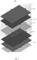
- FIG. 1 illustrates an exploded view of an example material stack for forming a microfluidic device 100.
- the microfluidic device 100 can include a plurality of layers that form the material stack.
- the microfluidic device 100 can include a basal channel layer 105 and an apical channel layer 110.
- the basal channel layer 105 and the apical channel layer 110 can be separated from one another by a permeable membrane 115.
- the basal channel layer 105 and the apical channel layer 110 can each define a respective network of one of more channels. Channels in the basal channel layer 105 can be complimentary to respective channels in the apical channel layer 110.
- portions of the channels in the apical channel layer 110 can overlap with portions of channels in the in the basal channel layer 105, with the overlapping portions in fluid communication with one another through the membrane 115.
- interactions between substances in the channels of the basal channel layer 105 and the channels of the apical channel layer 110 can occur.
- the microfluidic device 100 also includes a port layer 120.
- the port layer 120 can include openings or ports that can be aligned with channels in either the basal channel layer 105 or the apical channel layer 110. Fluid samples can be introduced into the channels of the basal channel layer 105 and the apical channel layer 110 via the ports of the port layer 120.
- the microfluidic device 100 can also include an optical layer 125.
- the optical layer 125 can provide optical access to the channels of the basal channel layer 105.
- the optical layer 125 can serve as an interface through which substances (e.g., fluid samples, cells, etc.) can be observed or imaged, such as with a microscope or other optical equipment.
- the microfluidic device 100 can also include additional or different layers not depicted in FIG. 1 .
- the microfluidic device 100 can include or be coupled to a well plate.
- the well plate can be integrated with port layer 120.
- the well plate also can be formed separately from the port layer 120, and be
- the microfluidic device 100 can be formed by bonding the layers shown in FIG. 1 to one another.
- conventional bonding techniques applied to these layers can cause problems in the resulting microfluidic device 100.
- bonding may require exposure of the layers to heat and pressure for long and repeated bond cycles. This can lead to shrinkage of certain portions of the layers, thereby resulting in poor alignment between adjacent layers.
- layers of the microfluidic device 100 can be formed from polymer materials, such as cyclic olefin polymer (COP), cyclic olefin copolymer (COC), or polystyrene.
- COP cyclic olefin polymer
- COC cyclic olefin copolymer
- polystyrene polystyrene
- the membrane 115 or the optical layer 125 may become distorted and therefore exhibit poor "flatness" after the bonding process, leading to decreased performance of the microfluidic device 100.
- FIG. 2 illustrates a top view of a portion of the microfluidic device 100 illustrated in FIG. 1 .
- the view of FIG. 2 depicts a channel 205 of the basal channel layer 105 and another channel 210 of the apical channel layer 110.
- the channel 205 can be formed as a part of the basal channel layer 105, for example as a recess or defined open region within the substrate of the basal channel layer 105.
- the other channel 210 can be formed as a part of the apical channel layer 110, for example as a recess or defined open region within the substrate of the apical channel layer 110.
- Each of the channels 205 and 210 can include a central portion as well as arm portions.
- the central portions of the channels 205 and 210 can overlap with one another.
- the central portions of the channels 205 and 210 can be separated from one another by the membrane 115 (not shown in FIG. 2 ) such that the channels 205 and 210 are in fluid communication with one another through the membrane 115.
- the channels 205 and 210 can be separated by any type of membrane or separation layer, such as a scaffold, semipermeable membrane, or other type of separation layer.
- the arm portions of the channels 205 and 210 can extend in various directions, including opposing directions, such that the channels 205 and 210 may not fully align with one another along their entire lengths.
- sections of the basal channel layer 105 that are positioned adjacent to the arm portion of the channel 210 defined by the apical channel layer 110 may be unsupported by the apical channel layer 110 itself, during the bonding process.
- sections of the apical channel layer 110 that are positioned adjacent to the arm portion of the channel 205 defined by the basal channel layer 105 may be unsupported by the basal channel layer 105 itself.
- These unsupported sections could collapse into the arm portion of the underlying channel in the adjacent layer when subjected to temperature and pressure during a bonding process. This can result in additional material deformation of the layers, as well as poor bond quality.
- FIG. 3 illustrates a cross-sectional view of an example material stack 300 for forming a microfluidic device similar to the microfluidic device 100 illustrated in FIG. 1 .
- the stack 300 can include at least one basal channel layer 305, at least one membrane 320, and at least one apical channel layer 340.
- the membrane 320 can separate the basal channel layer 305 from the apical channel layer 340.
- the stack 300 also includes a well plate 360.
- the layers of the stack 300 can be formed separately from one another. After formation, the layers can be bonded together to form a complete microfluidic device, such as the microfluidic device 100 depicted in FIG. 1 .
- the layers can be bonded to one another by ultrasonic welding (sometimes referred to as "ultrasonic bonding").
- Ultrasonic welding can include subjecting the layers of the stack 300 to high frequency vibrations, which can generate heat at the interface of adjacent layers of the stack 300. However, ultrasonic welding may require that the materials subjected to the highfrequency vibrations are compatible with one another.
- ultrasonic welding may require material compatibility between adjacent layers (e.g., COP/COP or COP/COC used for adjacent layers as well as that of the semi-permeable membrane 320) so that the adjacent layers have similar glass transition temperatures, thereby limiting design choices for the material stack 300.
- ultrasonic bonding may result in significant "flash", or excess material. This excess material may obstruct or interfere with portions of the microfluidic device 100, or otherwise cause an undesirable outcome.
- one or more pairs of adjacent layers in the stack 300 may be bonded to one another using ultrasonic welding, and other pairs of adjacent layers in the stack 300 may be bonded using other techniques.
- the basal channel layer 305, the membrane 320, and the apical channel layer 340 can be bonded using other means, and the well plate 360 can be adhered to the apical channel layer 340 via ultrasonic bonding. In either case, ultrasonic bonding may result in poor uniformity of the bond in areas where ultrasonic energy is poor, and may risk collapse or deformation of either or both of the basal channel layer 305 and the apical channel layer 340 into their respective channels.
- one or more pairs of adjacent layers in the stack 300 may instead be bonded using an insert molding technique.
- the basal channel layer 305, the membrane 320, and the apical channel layer 340 can first be adhered to one another using any bonding technique, and then well plate 360 can be over-molded on the apical channel layer 340 inside a mold.
- insert molding techniques may risk collapse or deformation of either or both of the basal channel layer 305 and the apical channel layer 340 into their respective channels when temperature and pressure are applied inside the mold.
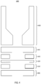
- FIG. 4 illustrates a cross-sectional view of another example material 400 stack for forming a microfluidic device similar to the microfluidic device 100 illustrated in FIG. 1 .
- the stack 400 can be similar to the stack 300 shown in FIG. 3 , however certain layers depicted in FIG. 3 are formed from more than one layer in the stack 400 of FIG. 4 .
- a basal channel layer e.g., the basal channel layer 305 described herein above in conjunction with FIG. 3 , etc.
- an apical channel layer e.g., the apical channel layer 340 described herein above in conjunction with FIG.
- a membrane 420 can separates the basal channel layer from the apical channel layer.
- the membrane 420 can be positioned between the layer 410 which forms a portion of the basal channel layer and the layer 440 that forms a portion of the apical channel layer.
- the stack 400 also includes a well plate 460.
- one or more of the layers of the stack 400 can be formed separately from one another.
- the layers can be bonded together to form a complete microfluidic device.
- at least some pairs of adjacent layers in the stack 400 can be bonded together using laser welding.
- laser welding In a laser welding process, laser energy can be passed through one layer and absorbed by another layer to heat and melt the interface between the two layers. Thus, the materials of the adjacent layers must be carefully selected.
- laser welding can risk burning or deforming a portion of layers. Bonding of the membrane 420 to the adjacent layers 420 and 440 also may be poor in unsupported areas, resulting in leak paths
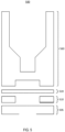
- FIG. 5 illustrates a cross-sectional view of an example material stack 500 for forming a microfluidic device similar to the microfluidic device 100 illustrated in FIG. 1 .
- the stack 500 can be similar to the stack 400 shown in FIG. 4 or the stack 300 shown in FIG. 3 , however certain layers of the stack 400 depicted in FIG. 4 or the stack 300 depicted in FIG. 3 can be formed integrally with one another in the stack 500 of FIG. 5 .
- an apical channel layer e.g., formed from the layers the first layer 440 and the second layer 445 in the stack 400 of FIG. 4 , the basal channel layer 340 in the stack 300 of FIG.
- the stack 500 can include a basal channel layer formed from layers 505 and 510 (e.g., similar to the layer 405 and a second layer 410, etc.), as well as a membrane 520.
- the layers of the stack 500 below the well plate 560 can be adhered to one another sequentially via laser welding to create the final microfluidic device.
- defects similar to those described above in connection with FIG. 4 may be introduced due to laser welding. For example, burning or material deformation may occur, particularly because multiple sequential laser welds may be required.
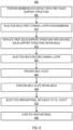
- FIG. 6 illustrates a flowchart of an example method 600 for fabricating a closed microfluidic device.
- FIGS. 7A-7G illustrate cross-sectional views of stages of construction of an example microfluidic device manufactured according to the example method 600 of FIG. 6.
- FIGS. 6 and 7A-7G are described together below.
- the method 600 can include positioning a membrane in contact with a first solid support structure (BLOCK 605).
- the method 600 can include injection molding a first channel layer over the membrane (BLOCK 610).
- the method 600 can include replacing the first solid support structure with a second solid support structure within the mold (BLOCK 615).
- the method 600 can include injection molding a second channel layer (BLOCK 620).
- the method 600 can include providing a well plate (BLOCK 625).
- the method 600 can include positioning the well plate within the mold (BLOCK 630).
- the method 600 can include injecting a polymer material into the mold to fill a cavity defined by the first channel layer and portions of the well plate (BLOCK 635).
- the method 600 can include curing the polymer material (BLOCK 640).
- the method 600 can include positioning a membrane in contact with a first solid support structure (BLOCK 605).
- the first solid support structure 705 can include a rectangular cross-sectional shape. Such a shape can provide a flat surface over which the membrane 720 can be positioned.
- the flat surface provided by the first solid support structure 705 can help to ensure that the membrane 720 retains a flat or planar shape.
- the membrane 720 can be similar to the membranes 115, 320, 420, and 520 depicted in FIGS. 1 and 3-5 .
- the membrane can be a layer of material formed from a polymer such as polycarbonate and defining a series of pores having a size selected to allow particles of a desired size or weight to pass through the membrane 720.
- the solid support structure 705 can have local features that can enable tensioning of the membrane 720.
- a geometry of the solid support structure 705 can be selected to impart tension on the membrane 720.
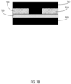
- the method 600 can include injection molding a first channel layer over the membrane (BLOCK 610). The results of this stage are depicted in FIG. 7B .
- another insert or support structure 715 can be used.
- the support structure 715 can be positioned on the opposite side of the membrane 720 from the first support structure 705.
- the support structure 715 can be shaped as a negative of the first channel layer 710.
- the support structure 715 can have a void in areas in which the first channel layer 710 is solid, and can be solid in areas that will define voids (e.g., a channel, a chamber, etc.) in the first channel layer 710.
- a polymer material, such as COC, COP, or polystyrene, among others, can be injected into the mold to fill the voids in the support structure 715, thereby defining the first channel layer 710.
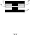
- the method 600 can include replacing the first solid support structure 705 with a second solid support structure within the mold (BLOCK 615).
- the results of this stage are shown in FIG. 7C .
- the first support structure 705 has been removed, and a second solid support structure 725 has been positioned in its place.
- the first solid support structure 705 can be removed, for example, by mechanical removal, or by dissolving or otherwise removing the first support structure 705 using a solvent or other chemical reaction.
- the second solid support structure 725 may not have a rectangular cross sectional shape. Instead, the second solid support structure 725 can have a shape selected according to a desired shape of a second channel layer to be formed in a subsequent operation.
- the second support structure 725 can be shaped as a negative of the second channel layer.
- the second support structure 725 can have voids in areas in which the second channel layer is solid, and can be solid in areas that will define voids (e.g., a channel, a chamber, etc.) in the second channel layer.
- the second solid support structure 725 can have a shape that is similar to the shape of the support structure 715.
- the second solid support structure 725 can be used to fabricate a second channel layer having a network of channels that is complementary to the network of channels defined by the first channel layer 710.
- channels may be referred to as "complementary" if a portion of the channels overlap with one another.
- a membrane such as the membrane 720 may separate the overlapping portion of complementary channels.
- a channel and its complement can be in fluidic communication with one another via the membrane 720.
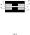
- the method 600 can include injection molding a second channel layer (BLOCK 620). The results of this stage are shown in FIG. 7D .
- a polymer material such as COC, COP, or polystyrene, among others, can be injected into the mold to fill the voids in the second support structure 725, thereby defining the second channel layer 730.
- the material selected for the second channel layer 730 can be the same material selected for the first channel layer 710. In some implementations, the material selected for the second channel layer 730 can be different from the material selected for the first channel layer 710.
- the method 600 can include providing a well plate (BLOCK 625).
- the well plate can be manufactured separately from the first channel layer 710 and the second channel layer 730 depicted in FIGS. 7A-7D .
- the well plate can be fabricated using a separate injection molding technique. An example of such a technique is depicted in FIG. 7E .
- a first mold piece 745 and a second mold piece 750 can be used.
- a polymer material, such as COC, COP, or polystyrene, among others, can be injected into the negative space defined by the first mold piece 745 and the second mold piece 750 to form the well plate 760.
- the material selected for the well plate 760 can be the same as the material selected for either or both of the first channel layer 710 or the second channel layer 730. In some implementations, the material selected for the second channel layer 730 can be different from the material selected for either or both of the first channel layer 710 and the second channel layer 730.
- the well plate 760 can be similar to the well plates 360, 460, and 560 shown in FIGS. 3-5 .
- the well plate 760 can include at least one central opening (e.g., defined by the second mold piece 750) through which a fluid sample can be introduced into an underlying channel or chamber after the well plate 760 is secured to a remainder of the microfluidic device.
- the well plate 760 can differ from the well plates 360, 460, and 560 in that the well plate 760 can include a sealing lip 762, which may also be referred to herein as a sealing portion 762.
- the sealing lip 762 can protrude from a remaining portion of the well plate 760, which can be referred to as a support portion of the well plate 760.
- the sealing lip 762 can at least partially surround the opening 764 defined by the well plate 760.
- the well plate 760 with the sealing lip 762 can be used to facilitate an improved bonding process that can result in better bond quality and less risk of damage to the well plate 760 or to other components (e.g., channel layers, membranes, etc.) of the microfluidic device, as described further below.
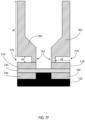
- the method 600 can include positioning the well plate within the mold (BLOCK 630).
- the well plate 760 can be positioned inside the mold such that sealing lip 762 of the well plate 760 is in contact with the first channel layer 710.
- the opening of the well plate 760 also can be aligned with a channel defined by the first channel layer 710.
- the sealing lip 762 can serve as a seal that surrounds the opening in the well plate 760.
- a gap can exist between the remaining portion of well plate 760 and the first channel layer 710.
- the gap can have a height that extends a distance labeled d2 and a width that extends a distance labeled d3 in FIG. 7F .
- the support portion can extend a distance labeled d1 in FIG. 7F
- the sealing lip 762 extends an additional distance d2.
- a cavity 770 can exist between the well plate 760 and the first channel layer 710.
- the cavity can span a width having the distance d3 and a height having the distance d2. This cavity 770 is sealed from the channel defined in the first channel layer 710 by the sealing lip 762.
- the method 600 can include injecting a polymer material into the mold to fill the cavity 770 defined by the first channel layer 710 and portions of the well plate 760 (BLOCK 635).
- the polymer material can be injected into the cavity 770. Because the sealing lip 762 seals the cavity 770 from the channel, the injected polymer material is prevented from leaking into the channel.
- the injection of the polymer material can be achieved through an injection molding process.
- the injected polymer material can adhere the well plate 760 to the first channel layer 710. This bonding technique therefore results in several technical improvements, relative to conventional laser welding, ultrasonic welding, and other techniques described above. For example, burning or warping of the materials of the well plate 760 and the first channel layer 710 can be avoided, because there is no need to use a technique such as laser welding that can subject the materials to temperatures that may cause such damage.
- a secure bond can be formed between the well plate 760 and the first channel layer 710 without the risk of collapsing any portion of the first channel layer 710, the membrane 720, or the second channel layer 730.
- bonding techniques that require pressure to be applied to a material stack can cause layers of the stack to deform out of plane (e.g., collapse into channels or chambers defined by adjacent layers) in areas where there may not be a rigid substrate or other support structure to prevent such collapse.
- Using the technique described in this disclosure which includes providing an well plate 760 having an sealing lip 762 and injecting a polymer material to fill the cavity 770 between the well plate 760 and the adjacent first channel layer 710, can dispense with the need to apply pressures that can increase the risk of layers collapsing during the bonding process.
- the dimensions of the sealing lip 762 and the cavity 770 can be selected to facilitate a strong bond between the well plate 760 and the first channel layer 710.
- the distance d2 e.g., the height of the sealing lip 762 or the distance to which the sealing lip 762 protrudes from the supporting portion of the well plate 760
- the distance d3 e.g., the width of the cavity 770
- the distance d2 can be selected to be substantially equal to the distance d2.
- the distance d3 can be selected to be about 25% larger than the distance d2, about 50% larger than the distance d2, or about 75% larger than the distance d2. In still other implementations, the distance d3 can be selected to about twice the distance d2, about three times the distance d2, about 4 times the distance d2, or about 5 times the distance d2. Other dimensions are also possible.
- BLOCK 635 The results of BLOCK 635 are shown in FIG. 7G .
- the well plate 760 and the first channel layer 710 are bonded by the injection of the polymer material in BLOCK 635 to form what appears to be a monolithic component after the injection of the polymer material is complete.
- the broken line 785 depicts the interface region between the first channel layer 710 and the well plate 760 for illustrative purposes, however it should be understood that in practice the well plate 760 and the first channel layer 710 may appear to a single integral component after the bonding process is complete.
- the method 600 can include curing the polymer material that was injected into the cavity 770 (BLOCK 640).
- the polymer material injected into the cavity 770 can be the same material as at least one of the well plate 760 and the first channel layer 710.
- the well plate 760, the first channel layer 710, and the polymer material injected into the cavity can each be selected to be the same material, or to be materials that are compatible with one another for bonding purposes via the injection molding technique described in this disclosure.
- the polymer material injected into the cavity 770 can be COP, COC, or polystyrene, among others.
- the method 600 can include additional or different steps than those depicted in FIG. 6 .
- additional or different layers or components can be added to the microfluidic device in other steps.
- the method 600 can include coupling an optical layer to the microfluidic device.
- an optical layer 785 can be added to the second channel layer 730, on the opposite side of the second channel layer 730 from the membrane 720 and the first channel layer 710.
- the second solid support structure 725 can be removed before the optical layer 785 is added.
- the optical layer 785 can be similar to the optical layer 125 shown in FIG. 1 .
- the optical layer 785 can be formed from a transparent material and can facilitate observation of fluid samples or other substances in the channels defined in the second channel layer 730.
- the optical layer 785 can be made from a transparent plastic or other type of transparent material, such as glass.
- the optical layer 785 can be coupled to the microfluidic device via one or more attachment processes described herein, including laser welding, ultrasonic welding, solvent bonding, or thermal bonding.
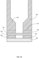
- FIG. 8 illustrates a cross-sectional view of an alternative geometry for components of the microfluidic device shown in FIGS. 7A-7G .
- the components of FIG. 8 are similar to the components shown in FIGS. 7A-7G , and like reference numerals refer to like components in these figures.
- the device shown in FIG. 8 differs from that shown in FIGS. 7A-7G in that the well plate 860 of FIG. 8 includes a sealing lip 862 having a beveled edge 895, rather than a straight edge.
- the beveled edge 895 extends downward at an angle away from the remaining portion of the well plate 860.
- first channel layer 810 also includes a beveled edge having an angle that matches the angle of the beveled edge 895, such that the beveled edge of the sealing lip 862 sits flush against the edge of the first channel layer 810.
- a polymer material can be injected into the cavity 870, similar to the process described above in connection with FIGS. 6 and 7A-7G .
- the sealing lip 862 can exert an outward force (e.g., away from the central axis of the opening of the well plate 860) on the first channel layer 810.
- the membrane 820 may be bonded or adhered to the first channel layer 810.
- the outward force exerted by the beveled edge 895 of the sealing lip 862 on the first channel layer 810 can introduce tension into the membrane 820, thereby increasing the flatness of the membrane 820.
- the membrane 820 may be less likely to collapse or deform out of plane (e.g., into the channels defined in the first channel layer 810 or the second channel layer 830.
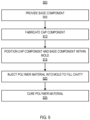
- FIG. 6 illustrates a flowchart of an example method 900 for fabricating such a closed microfluidic device.
- the method 900 can include providing a base component (BLOCK 905).
- the base component can define a first portion of a channel or a chamber of the microfluidic device.
- the base component can be a channel layer similar to either of the first channel layer 710 or the second channel layer 730 depicted in FIGS. 7A-7G .
- the base component can also include additional features.
- the base component itself may include a plurality of layers, each or which may define a respective channel or chamber (or a respective network of channels or chambers).
- the base component can be formed, for example, from a polymer material such as COC, COP, or polystyrene.
- the method 900 can include fabricating a cap component of the microfluidic device (BLOCK 910).
- the cap component can include a sealing lip.
- the sealing lip can be similar to the sealing lip 762 shown in FIG. 7E .
- the sealing lip can extend a first distance from a first side of the cap component.
- the sealing lip can protrude from a support portion of the cap component, which may extend a second distance, less than the first distance, from the first side of the cap component.
- the cap component may be a well plate, similar to the well plate 760 of FIGS. 7A-7G .
- the cap component can be a simpler component that may not include any openings providing access to interior channels.
- the cap component may instead define sidewalls and a ceiling or floor of a channel or chamber, similar to the first channel layer 710 or the second channel layer 730 depicted in FIGS. 7A-7G , with the addition of a sealing lip.
- the cap component can be formed from a polymer material such as COC, COP, or polystyrene, among others.
- the cap component can be formed from the same material as the base component.
- the method can include positioning the cap component and the base component within a mold (BLOCK 915).
- the cap component and the base component can be positioned inside the mold such that the sealing lip of the cap component is brought in contact with the base component.
- the base component can be spaced away from the support portion of the cap component by a third distance equal to a difference between the first distance and the second distance.
- the base component, the support portion of the cap component, and the sealing lip of the cap component together can define a cavity that is sealed from the channel of the microfluidic device by the sealing lip of the cap component.
- the method can include injecting a polymer material into the mold to cause the polymer material to fill at least a portion of the cavity defined by the base component, the support portion of the cap component, and the sealing lip of the cap component (BLOCK 920).
- the injected polymer material can cause the base component to become adhered to the cap component.
- the polymer material can be the same material as one or both of the base component and the cap component.
- the base component, the cap component, and the polymer material injected into the cavity can each be selected to be the same material, or to be materials that are compatible with one another for bonding purposes via the injection molding technique described in this disclosure.
- the polymer material injected into the cavity can be COP, COC, or polystyrene.
- the method can also include curing the polymer material to secure the base component to the cap component (BLOCK 925). After the polymer material is cured, the base component and the cap component may be bonded to form what appears to be a monolithic microfluidic device. In some implementations, other components may be added to the microfluidic device in additional steps. For example, an optical layer may be added to allow for fluid samples or other substances inside the microfluidic device to be observed or imaged.
- FIGS. 10A-10C illustrate cross-sectional views of material stacks that can be used to form closed microfluidic devices.
- the material stacks shown in FIGS. 10A-10C show the distinctions between devices manufactured using traditional bonding techniques as compared to devices fabricated using the injection molding technique described in this disclosure.
- a material stack 1010 is shown.
- the material stack 1010 includes a cap component 1015 and a base component 1020.
- the cap component 1015 and the base component 1020 meet at a flat interface suitable for bonding via conventional techniques. As described above, such techniques typically require at least one a temperature or a pressure that risks damaging components of the device, such as by burning the materials or causing material deformation or collapse.
- FIGS. 10B and 10C show material stacks that make use of a sealing lip to facilitate bonding via injection molding, as described above.
- the material stacks of FIGS. 10B and 10C can be bonded to one another to produce a closed microfluidic device using the method 900 described above in connection with FIG. 9 .
- a material stack 1050 is shown.
- the material stack 1050 includes a cap component 1055 and a base component 1060.
- the cap component 1055 includes a sealing lip 1065 that extends away from a remaining portion of the cap component 1055. When the cap component 1055 is brought in contact with the base component 1060, as depicted in FIG.
- the sealing lip 1065 of the cap component 1055 rests against the flat surface of the base component 1060, leaving a cavity 1070 that is sealed off from the central channel of the device.
- a polymer material can be injected into the cavity 1070. The polymer material can bond the cap component 1055 to the base component 1060, while the sealing lip 1065 prevents the injected polymer material from leaking into the central channel of the device.
- FIG. 10C shows a material stack 1080 having a cap component 1085 and a base component 1090.
- the cap component 1085 includes a sealing lip 1095.
- the sealing lip 1095 of FIG. 10C extends across the entire central channel defined between the cap component 1085 and the base component 1090, rather than surrounding the channel.
- a cavity 1098 exists outside of the lip 1098 when the cap component 1085 is positioned in contact with the base component 1090 in the arrangement shown in FIG. 10C .
- the cavity 1098 is sealed off from the central channel of the device.
- a polymer material can be injected into the cavity 1095.
- the polymer material can bond the cap component 1085 to the base component 1090, while the sealing lip 1095 prevents the injected polymer material from leaking into the central channel of the device.
- FIGS. 10B and 10C are illustrative only, and that microfluidic devices can be manufactured using a material stack that includes a sealing lip to define a cavity with other geometries as well.
- the sealing lip could instead be a portion of the base component, rather than the cap component.
- Other variations are also possible.
- These arrangements can overcome technical challenges of using conventional bonding techniques and material stack geometries, which can have adverse effects on the materials that form the base component and cap component. For example, as described above, some bonding techniques may burn or melt portions of the base component or cap component.
- the microfluidic device may have dimensions that are distorted as a result of such burning or melting.
- the manufacturing techniques provided in this disclosure allow for fabrication of closed microfluidic devices in a manner that overcomes these challenges.
- the geometry and dimensions of the base component or the cap component can be selected to facilitate injection molding in a manner that prevents or reduces deformation of the microfluidic device that may otherwise occur as a result of temperatures and pressures applied during the molding process.
Landscapes
- Chemical & Material Sciences (AREA)
- Health & Medical Sciences (AREA)
- Engineering & Computer Science (AREA)
- Analytical Chemistry (AREA)
- Manufacturing & Machinery (AREA)
- General Health & Medical Sciences (AREA)
- Hematology (AREA)
- Clinical Laboratory Science (AREA)
- Chemical Kinetics & Catalysis (AREA)
- Dispersion Chemistry (AREA)
- Mechanical Engineering (AREA)
- Microelectronics & Electronic Packaging (AREA)
- Micromachines (AREA)
- Injection Moulding Of Plastics Or The Like (AREA)
Claims (15)
- Ein Verfahren (900), das Folgendes beinhaltet:Bereitstellen (905) einer Basiskomponente (710; 810; 1060; 1090), um einen ersten Abschnitt eines Kanals einer mikrofluidischen Vorrichtung zu definieren;Fertigen (910) einer Deckelkomponente (760; 860; 1055; 1085) der mikrofluidischen Vorrichtung,dadurch gekennzeichnet, dass die Deckelkomponente eine Dichtlippe (762; 862; 1065; 1095), die sich von einer ersten Seite der Deckelkomponente über eine erste Entfernung erstreckt, und einen Trägerabschnitt, der sich von der ersten Seite der Deckelkomponente über eine zweite Entfernung (d1), die kleiner als die erste Entfernung ist, erstreckt, beinhaltet;und dass das Verfahren ebenfalls Folgendes beinhaltet:Positionieren (915) der Deckelkomponente und der Basiskomponente innerhalb einer Form, um die Dichtlippe der Deckelkomponente in Berührung mit der Basiskomponente zu bringen, wobei die Basiskomponente von dem Trägerabschnitt der Deckelkomponente um eine dritte Entfernung (d2), die gleich einer Differenz zwischen der ersten Entfernung und der zweiten Entfernung ist, beabstandet ist;Einspritzen (920) eines Polymermaterials in die Form, um zu bewirken, dass das Polymermaterial mindestens einen Abschnitt eines durch die Basiskomponente, den Trägerabschnitt der Deckelkomponente und die Dichtlippe der Deckelkomponente definierten Hohlraums (770; 870; 1070; 1098) füllt, wobei der Hohlraum durch die Dichtlippe der Deckelkomponente hinsichtlich des Kanals der mikrofluidischen Vorrichtung abgedichtet ist; undHärten (925) des Polymermaterials, um die Basiskomponente an der Deckelkomponente zu befestigen.
- Verfahren gemäß Anspruch 1, das ferner Folgendes beinhaltet:
Bilden einer optischen Schicht (125; 785), die ein transparentes Material beinhaltet; und Koppeln der optischen Schicht mit einer von der Basiskomponente oder der Deckelkomponente, um die Beobachtung der mikrofluidischen Vorrichtung zu erleichtern, unter Verwendung von mindestens einem von Laserschweißen, Ultraschallschweißen, Lösungsmittelkleben oder Wärmekleben. - Verfahren gemäß Anspruch 1, wobei die Basiskomponente und die Deckelkomponente aus einem Material gebildet sind, das sich von dem in den Hohlraum eingespritzten Polymermaterial unterscheidet.
- Verfahren gemäß Anspruch 1, wobei das Polymermaterial mindestens eines von Folgendem beinhaltet: Cycloolefinpolymer, COP, Cycloolefin-Copolymer, COC, oder Polystyrol.
- Verfahren gemäß Anspruch 1, wobei die Deckelkomponente eine Decke oder eine Seitenwand des Kanals der mikrofluidischen Vorrichtung definiert.
- Verfahren gemäß Anspruch 1, wobei die Deckelkomponente eine Mikrotiterplatte beinhaltet, die mindestens eine Öffnung definiert, welche konfiguriert ist, um nach dem Härten des Polymermaterials mit dem Kanal der mikrofluidischen Vorrichtung in Fluidverbindung zu stehen.
- Verfahren gemäß Anspruch 6, das ferner das Fertigen der Deckelkomponente, die die Mikrotiterplatte beinhaltet, unter Verwendung von Spritzgießen beinhaltet.
- Verfahren gemäß Anspruch 6, wobei die Deckelkomponente so gefertigt wird, dass die Dichtlippe die mindestens eine Öffnung der Mikrotiterplatte mindestens teilweise umgibt.
- Verfahren gemäß Anspruch 1, wobei der Kanal ein erster Kanal ist und wobei die Basiskomponente (730; 830) ferner mindestens einen Abschnitt eines zweiten Kanals definiert.
- Verfahren gemäß Anspruch 9, wobei der erste Kanal (205) und der zweite Kanal (210) durch eine semipermeable Membran (115; 720; 820) getrennt sind.
- Verfahren gemäß Anspruch 9, das ferner das Spritzgießen mindestens eines Abschnitts der Basiskomponente beinhaltet.
- Verfahren gemäß Anspruch 11, das ferner Folgendes beinhaltet:Positionieren (600) einer ersten Seite einer Membran in Berührung mit einer ersten festen Trägerstruktur innerhalb einer Form;Spritzgießen (610) einer ersten Kanalschicht über einer zweiten Seite der Membran, die der ersten Seite der Membran entgegengesetzt ist, um zu bewirken, dass die erste Kanalschicht an der zweiten Seite der Membran anhaftet, wobei die erste Kanalschicht mindestens einen Abschnitt des ersten Kanals definiert;Ersetzen (615) der ersten festen Trägerstruktur durch eine zweite feste Trägerstruktur innerhalb der Form, wobei die zweite feste Trägerstruktur die erste Seite der Membran berührt, wobei die zweite feste Trägerstruktur eine Gestalt aufweist, die einem zweiten Netz von Kanälen, das den zweiten Kanal einschließt, entspricht; undSpritzgießen (620) einer zweiten Kanalschicht auf der ersten Seite der Membran, um zu bewirken, dass die zweite Kanalschicht an der ersten Seite der Membran anhaftet,wobei die zweite Kanalschicht das zweite Netz von Kanälen, das mindestens einen Abschnitt des zweiten Kanals einschließt, definiert.
- Verfahren gemäß Anspruch 1, wobei die Deckelkomponente so gefertigt wird, dass die Dichtlippe der Deckelkomponente eine abgeschrägte Kante beinhaltet.
- Eine mikrofluidische Vorrichtung, die Folgendes beinhaltet:
eine Basiskomponente (710; 810; 1060; 1090), die mindestens einen Abschnitt eines ersten Kanals der mikrofluidischen Vorrichtung definiert; und eine Deckelkomponente, wobei die mikrofluidische Vorrichtung durch Folgendes gekennzeichnet ist:eine Deckelkomponente (760; 860; 1055; 1085), die eine Dichtlippe (762; 862; 1065; 1095), die sich von einer ersten Seite der Deckelkomponente über eine erste Entfernung erstreckt, und einen Trägerabschnitt, der sich von der ersten Seite der Deckelkomponente über eine zweite Entfernung, die kleiner als die erste Entfernung ist, erstreckt, beinhaltet; undein Polymermaterial, das mindestens einen Abschnitt eines durch die Basiskomponente, den Trägerabschnitt der Deckelkomponente und die Dichtlippe der Deckelkomponente definierten Hohlraums (770; 870; 1070; 1098) füllt, wobei der Hohlraum durch die Dichtlippe der Deckelkomponente hinsichtlich des Kanals der mikrofluidischen Vorrichtung abgedichtet ist,wobei das Polymermaterial spritzgegossen wird, um den Hohlraum zu füllen, und gehärtet wird, um die Basiskomponente an der Deckelkomponente zu befestigen. - Ein Verfahren, das Folgendes beinhaltet:Positionieren (605) einer ersten Seite einer Membran in Berührung mit einer ersten festen Trägerstruktur innerhalb einer Form;Spritzgießen (610) einer ersten Kanalschicht über einer zweiten Seite der Membran, die der ersten Seite der Membran entgegengesetzt ist, um zu bewirken, dass die erste Kanalschicht an der zweiten Seite der Membran anhaftet, wobei die erste Kanalschicht ein erstes Netz von Kanälen definiert;Ersetzen (615) der ersten festen Trägerstruktur durch eine zweite feste Trägerstruktur innerhalb der Form, wobei die zweite feste Trägerstruktur die erste Seite der Membran berührt, wobei die zweite feste Trägerstruktur eine Gestalt aufweist, die einem zweiten Netz von Kanälen entspricht;Spritzgießen (620) einer zweiten Kanalschicht auf der ersten Seite der Membran, um zu bewirken, dass die zweite Kanalschicht an der ersten Seite der Membran anhaftet,wobei die zweite Kanalschicht das zweite Netz von Kanälen definiert;Bereitstellen (625) einer Mikrotiterplatte, die mindestens eine Öffnung definiert, wobei die Mikrotiterplatte eine Dichtlippe, die sich von einer ersten Seite der Mikrotiterplatte über eine erste Entfernung erstreckt, und einen Trägerabschnitt, der sich von der ersten Seite der Deckelkomponente über eine zweite Entfernung, die kleiner als die erste Entfernung ist, erstreckt, beinhaltet; wobei die Dichtlippe die mindestens eine Öffnung mindestens teilweise umgibt;Positionieren (630) der Mikrotiterplatte innerhalb der Form, um die Dichtlippe der Mikrotiterplatte mit der ersten Kanalschicht in Berührung zu bringen und um die mindestens eine Öffnung der Mikrotiterplatte nach mindestens einem Kanal des ersten Netzes von Kanälen auszurichten, wobei die erste Kanalschicht um eine dritte Entfernung, die gleich einer Differenz zwischen der ersten Entfernung und der zweiten Entfernung ist, von dem Trägerabschnitt der Mikrotiterplatte beabstandet ist;Einspritzen (635) eines Polymermaterials in die Form, um zu bewirken, dass das Polymermaterial mindestens einen Abschnitt eines durch die erste Kanalschicht, den Trägerabschnitt der Mikrotiterplatte und die Dichtlippe der Mikrotiterplatte definierten Hohlraums füllt, wobei der Hohlraum durch die Dichtlippe der Deckelkomponente hinsichtlich des Kanals der mikrofluidischen Vorrichtung abgedichtet ist; undHärten (640) des Polymermaterials, um die Mikrotiterplatte an der ersten Kanalschicht zu befestigen.
Applications Claiming Priority (2)
| Application Number | Priority Date | Filing Date | Title |
|---|---|---|---|
| US201962905665P | 2019-09-25 | 2019-09-25 | |
| PCT/US2020/052470 WO2021061966A1 (en) | 2019-09-25 | 2020-09-24 | Systems and methods for manufacturing closed microfluidic devices |
Publications (2)
| Publication Number | Publication Date |
|---|---|
| EP4034492A1 EP4034492A1 (de) | 2022-08-03 |
| EP4034492B1 true EP4034492B1 (de) | 2023-12-27 |
Family
ID=72753028
Family Applications (1)
| Application Number | Title | Priority Date | Filing Date |
|---|---|---|---|
| EP20786679.9A Active EP4034492B1 (de) | 2019-09-25 | 2020-09-24 | Systeme und verfahren zur herstellung von geschlossenen mikrofluidischen vorrichtungen |
Country Status (5)
| Country | Link |
|---|---|
| US (1) | US11701652B2 (de) |
| EP (1) | EP4034492B1 (de) |
| JP (1) | JP7618655B2 (de) |
| CA (1) | CA3152341A1 (de) |
| WO (1) | WO2021061966A1 (de) |
Families Citing this family (5)
| Publication number | Priority date | Publication date | Assignee | Title |
|---|---|---|---|---|
| CN108872555B (zh) | 2013-03-11 | 2021-04-09 | 克忧健康公司 | 用于检测和量化分析物的系统和方法 |
| USD745423S1 (en) | 2014-05-12 | 2015-12-15 | Cue Inc. | Automated analyzer test cartridge and sample collection device for analyte detection |
| EP4434628A1 (de) | 2015-07-17 | 2024-09-25 | Cue Health Inc. | Systeme und verfahren für verbesserten nachweis und quantifizierung von analyten |
| WO2018140540A1 (en) | 2017-01-25 | 2018-08-02 | Cue Health Inc. | Systems and methods for enhanced detection and quantification of analytes |
| CA3223497A1 (en) * | 2021-07-30 | 2023-02-02 | Steven Michael VENZ | An analyte detection system cartridge with improved phase changeable valves |
Family Cites Families (11)
| Publication number | Priority date | Publication date | Assignee | Title |
|---|---|---|---|---|
| SE522801C2 (sv) | 2001-03-09 | 2004-03-09 | Erysave Ab | Anordning för att separera suspenderade partiklar från en fluid med ultraljud samt metod för sådan separering |
| US7060227B2 (en) * | 2001-08-06 | 2006-06-13 | Sau Lan Tang Staats | Microfluidic devices with raised walls |
| WO2005075975A1 (ja) * | 2004-02-06 | 2005-08-18 | Nec Corporation | 制御構造、分離装置およびグラディエント形成装置ならびにそれらを用いるマイクロチップ |
| JP2007525667A (ja) * | 2004-02-17 | 2007-09-06 | ヘンケル カーゲーアーアー | マイクロ流体分析用デバイス |
| WO2006046164A1 (en) * | 2004-10-27 | 2006-05-04 | Koninklijke Philips Electronics N. V. | Fluid container composed of two plates |
| US7618576B2 (en) * | 2004-11-12 | 2009-11-17 | Phoenix S&T, Inc. | Microfluidic array devices and methods of manufacture thereof |
| JP4496934B2 (ja) * | 2004-11-19 | 2010-07-07 | スターライト工業株式会社 | マイクロ化学デバイスの製造方法 |
| JP4591054B2 (ja) * | 2004-11-24 | 2010-12-01 | パナソニック株式会社 | 光学的分析デバイス |
| WO2012017515A1 (ja) | 2010-08-03 | 2012-02-09 | ミライアル株式会社 | マイクロ流路デバイス |
| JP2015020122A (ja) * | 2013-07-19 | 2015-02-02 | 独立行政法人理化学研究所 | マイクロチャンバー |
| US20180326415A1 (en) * | 2015-03-05 | 2018-11-15 | STRATEC CONSUMABLES GmbH | Microfluidic device and method of manufacture of microfluidic device |
-
2020
- 2020-09-24 EP EP20786679.9A patent/EP4034492B1/de active Active
- 2020-09-24 CA CA3152341A patent/CA3152341A1/en active Pending
- 2020-09-24 JP JP2022518664A patent/JP7618655B2/ja active Active
- 2020-09-24 WO PCT/US2020/052470 patent/WO2021061966A1/en not_active Ceased
- 2020-09-24 US US17/031,146 patent/US11701652B2/en active Active
Also Published As
| Publication number | Publication date |
|---|---|
| JP2022549297A (ja) | 2022-11-24 |
| JP7618655B2 (ja) | 2025-01-21 |
| WO2021061966A1 (en) | 2021-04-01 |
| US20210086178A1 (en) | 2021-03-25 |
| CA3152341A1 (en) | 2021-04-21 |
| US11701652B2 (en) | 2023-07-18 |
| EP4034492A1 (de) | 2022-08-03 |
Similar Documents
| Publication | Publication Date | Title |
|---|---|---|
| EP4034492B1 (de) | Systeme und verfahren zur herstellung von geschlossenen mikrofluidischen vorrichtungen | |
| US7060227B2 (en) | Microfluidic devices with raised walls | |
| US6425972B1 (en) | Methods of manufacturing microfabricated substrates | |
| US7862000B2 (en) | Microfluidic method and structure with an elastomeric gas-permeable gasket | |
| US20070012891A1 (en) | Prototyping methods and devices for microfluidic components | |
| CN108010868B (zh) | 包括可压缩结构的成型装置 | |
| US20200061614A1 (en) | Microfluidic chip and microfluidic device | |
| KR20090006053A (ko) | 엘라스토머 가스 투과성 가스켓을 가지는 미세유체 방법 및구조 | |
| US10500586B2 (en) | Microfluidic device with anti-wetting, venting areas | |
| KR101708990B1 (ko) | 마이크로 공압 밸브 소자 및 그 제조방법 | |
| TW200950955A (en) | Injection molding method and injection molding die | |
| US20220362774A1 (en) | Microfluidic chips with one or more vias | |
| US12103246B2 (en) | Method of bonding substrates, microchip and method of manufacturing the same | |
| US8697236B2 (en) | Fine line bonding and/or sealing system and method | |
| US20070160502A1 (en) | Microfluidic device and method of fabricating the same | |
| Lee et al. | Ultrasonic bonding method for heterogeneous microstructures using self-balancing jig | |
| US12434962B2 (en) | Method for fabricating a microfluidic device | |
| TWI760686B (zh) | 用於製造微流體結構的方法及具有微流體結構的設備 | |
| CN115532327B (zh) | 三明治结构的微流控芯片的制备方法及流体填充方法 | |
| Andreassen et al. | BioMEMS meets lab-on-a-chip: Heterogeneous integration of silicon MEMS and NEMS in polymer microfluidics | |
| AU2019387109A1 (en) | Thermoplastic forming tools, assemblages thereof, and methods of making and methods of use thereof | |
| JP4171936B2 (ja) | 樹脂接合型光学素子の樹脂成形用金型及び製造方法 | |
| EP3912791B1 (de) | Form zum formen von basismaterial mit integrierter dichtung | |
| KR102777741B1 (ko) | 막-전극 접합체 쉘, 이를 포함하는 막-전극 접합체 및 막-전극 접합체의 제조방법 | |
| Mielnik et al. | Heterogeneous integration of silicon fluidic components in polymer chips |
Legal Events
| Date | Code | Title | Description |
|---|---|---|---|
| STAA | Information on the status of an ep patent application or granted ep patent |
Free format text: STATUS: UNKNOWN |
|
| STAA | Information on the status of an ep patent application or granted ep patent |
Free format text: STATUS: THE INTERNATIONAL PUBLICATION HAS BEEN MADE |
|
| PUAI | Public reference made under article 153(3) epc to a published international application that has entered the european phase |
Free format text: ORIGINAL CODE: 0009012 |
|
| STAA | Information on the status of an ep patent application or granted ep patent |
Free format text: STATUS: REQUEST FOR EXAMINATION WAS MADE |
|
| 17P | Request for examination filed |
Effective date: 20220322 |
|
| AK | Designated contracting states |
Kind code of ref document: A1 Designated state(s): AL AT BE BG CH CY CZ DE DK EE ES FI FR GB GR HR HU IE IS IT LI LT LU LV MC MK MT NL NO PL PT RO RS SE SI SK SM TR |
|
| DAV | Request for validation of the european patent (deleted) | ||
| DAX | Request for extension of the european patent (deleted) | ||
| RIC1 | Information provided on ipc code assigned before grant |
Ipc: B81C 3/00 20060101ALI20230512BHEP Ipc: B29C 45/16 20060101ALI20230512BHEP Ipc: B01L 3/00 20060101ALI20230512BHEP Ipc: B81C 1/00 20060101AFI20230512BHEP |
|
| P01 | Opt-out of the competence of the unified patent court (upc) registered |
Effective date: 20230614 |
|
| GRAP | Despatch of communication of intention to grant a patent |
Free format text: ORIGINAL CODE: EPIDOSNIGR1 |
|
| STAA | Information on the status of an ep patent application or granted ep patent |
Free format text: STATUS: GRANT OF PATENT IS INTENDED |
|
| INTG | Intention to grant announced |
Effective date: 20230721 |
|
| GRAS | Grant fee paid |
Free format text: ORIGINAL CODE: EPIDOSNIGR3 |
|
| GRAA | (expected) grant |
Free format text: ORIGINAL CODE: 0009210 |
|
| STAA | Information on the status of an ep patent application or granted ep patent |
Free format text: STATUS: THE PATENT HAS BEEN GRANTED |
|
| AK | Designated contracting states |
Kind code of ref document: B1 Designated state(s): AL AT BE BG CH CY CZ DE DK EE ES FI FR GB GR HR HU IE IS IT LI LT LU LV MC MK MT NL NO PL PT RO RS SE SI SK SM TR |
|
| REG | Reference to a national code |
Ref country code: GB Ref legal event code: FG4D |
|
| REG | Reference to a national code |
Ref country code: CH Ref legal event code: EP |
|
| REG | Reference to a national code |
Ref country code: DE Ref legal event code: R096 Ref document number: 602020023492 Country of ref document: DE |
|
| REG | Reference to a national code |
Ref country code: IE Ref legal event code: FG4D |
|
| PG25 | Lapsed in a contracting state [announced via postgrant information from national office to epo] |
Ref country code: GR Free format text: LAPSE BECAUSE OF FAILURE TO SUBMIT A TRANSLATION OF THE DESCRIPTION OR TO PAY THE FEE WITHIN THE PRESCRIBED TIME-LIMIT Effective date: 20240328 |
|
| REG | Reference to a national code |
Ref country code: LT Ref legal event code: MG9D |
|
| PG25 | Lapsed in a contracting state [announced via postgrant information from national office to epo] |
Ref country code: LT Free format text: LAPSE BECAUSE OF FAILURE TO SUBMIT A TRANSLATION OF THE DESCRIPTION OR TO PAY THE FEE WITHIN THE PRESCRIBED TIME-LIMIT Effective date: 20231227 |
|
| PG25 | Lapsed in a contracting state [announced via postgrant information from national office to epo] |
Ref country code: ES Free format text: LAPSE BECAUSE OF FAILURE TO SUBMIT A TRANSLATION OF THE DESCRIPTION OR TO PAY THE FEE WITHIN THE PRESCRIBED TIME-LIMIT Effective date: 20231227 |
|
| PG25 | Lapsed in a contracting state [announced via postgrant information from national office to epo] |
Ref country code: LT Free format text: LAPSE BECAUSE OF FAILURE TO SUBMIT A TRANSLATION OF THE DESCRIPTION OR TO PAY THE FEE WITHIN THE PRESCRIBED TIME-LIMIT Effective date: 20231227 Ref country code: GR Free format text: LAPSE BECAUSE OF FAILURE TO SUBMIT A TRANSLATION OF THE DESCRIPTION OR TO PAY THE FEE WITHIN THE PRESCRIBED TIME-LIMIT Effective date: 20240328 Ref country code: FI Free format text: LAPSE BECAUSE OF FAILURE TO SUBMIT A TRANSLATION OF THE DESCRIPTION OR TO PAY THE FEE WITHIN THE PRESCRIBED TIME-LIMIT Effective date: 20231227 Ref country code: ES Free format text: LAPSE BECAUSE OF FAILURE TO SUBMIT A TRANSLATION OF THE DESCRIPTION OR TO PAY THE FEE WITHIN THE PRESCRIBED TIME-LIMIT Effective date: 20231227 Ref country code: BG Free format text: LAPSE BECAUSE OF FAILURE TO SUBMIT A TRANSLATION OF THE DESCRIPTION OR TO PAY THE FEE WITHIN THE PRESCRIBED TIME-LIMIT Effective date: 20240327 |
|
| REG | Reference to a national code |
Ref country code: NL Ref legal event code: MP Effective date: 20231227 |
|
| REG | Reference to a national code |
Ref country code: AT Ref legal event code: MK05 Ref document number: 1644368 Country of ref document: AT Kind code of ref document: T Effective date: 20231227 |
|
| PG25 | Lapsed in a contracting state [announced via postgrant information from national office to epo] |
Ref country code: NL Free format text: LAPSE BECAUSE OF FAILURE TO SUBMIT A TRANSLATION OF THE DESCRIPTION OR TO PAY THE FEE WITHIN THE PRESCRIBED TIME-LIMIT Effective date: 20231227 |
|
| PG25 | Lapsed in a contracting state [announced via postgrant information from national office to epo] |
Ref country code: SE Free format text: LAPSE BECAUSE OF FAILURE TO SUBMIT A TRANSLATION OF THE DESCRIPTION OR TO PAY THE FEE WITHIN THE PRESCRIBED TIME-LIMIT Effective date: 20231227 Ref country code: RS Free format text: LAPSE BECAUSE OF FAILURE TO SUBMIT A TRANSLATION OF THE DESCRIPTION OR TO PAY THE FEE WITHIN THE PRESCRIBED TIME-LIMIT Effective date: 20231227 Ref country code: NO Free format text: LAPSE BECAUSE OF FAILURE TO SUBMIT A TRANSLATION OF THE DESCRIPTION OR TO PAY THE FEE WITHIN THE PRESCRIBED TIME-LIMIT Effective date: 20240327 Ref country code: NL Free format text: LAPSE BECAUSE OF FAILURE TO SUBMIT A TRANSLATION OF THE DESCRIPTION OR TO PAY THE FEE WITHIN THE PRESCRIBED TIME-LIMIT Effective date: 20231227 Ref country code: LV Free format text: LAPSE BECAUSE OF FAILURE TO SUBMIT A TRANSLATION OF THE DESCRIPTION OR TO PAY THE FEE WITHIN THE PRESCRIBED TIME-LIMIT Effective date: 20231227 Ref country code: HR Free format text: LAPSE BECAUSE OF FAILURE TO SUBMIT A TRANSLATION OF THE DESCRIPTION OR TO PAY THE FEE WITHIN THE PRESCRIBED TIME-LIMIT Effective date: 20231227 |
|
| PG25 | Lapsed in a contracting state [announced via postgrant information from national office to epo] |
Ref country code: IS Free format text: LAPSE BECAUSE OF FAILURE TO SUBMIT A TRANSLATION OF THE DESCRIPTION OR TO PAY THE FEE WITHIN THE PRESCRIBED TIME-LIMIT Effective date: 20240427 |
|
| PG25 | Lapsed in a contracting state [announced via postgrant information from national office to epo] |
Ref country code: AT Free format text: LAPSE BECAUSE OF FAILURE TO SUBMIT A TRANSLATION OF THE DESCRIPTION OR TO PAY THE FEE WITHIN THE PRESCRIBED TIME-LIMIT Effective date: 20231227 Ref country code: CZ Free format text: LAPSE BECAUSE OF FAILURE TO SUBMIT A TRANSLATION OF THE DESCRIPTION OR TO PAY THE FEE WITHIN THE PRESCRIBED TIME-LIMIT Effective date: 20231227 |
|
| PG25 | Lapsed in a contracting state [announced via postgrant information from national office to epo] |
Ref country code: SK Free format text: LAPSE BECAUSE OF FAILURE TO SUBMIT A TRANSLATION OF THE DESCRIPTION OR TO PAY THE FEE WITHIN THE PRESCRIBED TIME-LIMIT Effective date: 20231227 |
|
| PG25 | Lapsed in a contracting state [announced via postgrant information from national office to epo] |
Ref country code: SM Free format text: LAPSE BECAUSE OF FAILURE TO SUBMIT A TRANSLATION OF THE DESCRIPTION OR TO PAY THE FEE WITHIN THE PRESCRIBED TIME-LIMIT Effective date: 20231227 Ref country code: SK Free format text: LAPSE BECAUSE OF FAILURE TO SUBMIT A TRANSLATION OF THE DESCRIPTION OR TO PAY THE FEE WITHIN THE PRESCRIBED TIME-LIMIT Effective date: 20231227 Ref country code: RO Free format text: LAPSE BECAUSE OF FAILURE TO SUBMIT A TRANSLATION OF THE DESCRIPTION OR TO PAY THE FEE WITHIN THE PRESCRIBED TIME-LIMIT Effective date: 20231227 Ref country code: IT Free format text: LAPSE BECAUSE OF FAILURE TO SUBMIT A TRANSLATION OF THE DESCRIPTION OR TO PAY THE FEE WITHIN THE PRESCRIBED TIME-LIMIT Effective date: 20231227 Ref country code: IS Free format text: LAPSE BECAUSE OF FAILURE TO SUBMIT A TRANSLATION OF THE DESCRIPTION OR TO PAY THE FEE WITHIN THE PRESCRIBED TIME-LIMIT Effective date: 20240427 Ref country code: EE Free format text: LAPSE BECAUSE OF FAILURE TO SUBMIT A TRANSLATION OF THE DESCRIPTION OR TO PAY THE FEE WITHIN THE PRESCRIBED TIME-LIMIT Effective date: 20231227 Ref country code: CZ Free format text: LAPSE BECAUSE OF FAILURE TO SUBMIT A TRANSLATION OF THE DESCRIPTION OR TO PAY THE FEE WITHIN THE PRESCRIBED TIME-LIMIT Effective date: 20231227 Ref country code: AT Free format text: LAPSE BECAUSE OF FAILURE TO SUBMIT A TRANSLATION OF THE DESCRIPTION OR TO PAY THE FEE WITHIN THE PRESCRIBED TIME-LIMIT Effective date: 20231227 |
|
| PG25 | Lapsed in a contracting state [announced via postgrant information from national office to epo] |
Ref country code: PL Free format text: LAPSE BECAUSE OF FAILURE TO SUBMIT A TRANSLATION OF THE DESCRIPTION OR TO PAY THE FEE WITHIN THE PRESCRIBED TIME-LIMIT Effective date: 20231227 Ref country code: PT Free format text: LAPSE BECAUSE OF FAILURE TO SUBMIT A TRANSLATION OF THE DESCRIPTION OR TO PAY THE FEE WITHIN THE PRESCRIBED TIME-LIMIT Effective date: 20240429 |
|
| PG25 | Lapsed in a contracting state [announced via postgrant information from national office to epo] |
Ref country code: PT Free format text: LAPSE BECAUSE OF FAILURE TO SUBMIT A TRANSLATION OF THE DESCRIPTION OR TO PAY THE FEE WITHIN THE PRESCRIBED TIME-LIMIT Effective date: 20240429 Ref country code: PL Free format text: LAPSE BECAUSE OF FAILURE TO SUBMIT A TRANSLATION OF THE DESCRIPTION OR TO PAY THE FEE WITHIN THE PRESCRIBED TIME-LIMIT Effective date: 20231227 |
|
| REG | Reference to a national code |
Ref country code: DE Ref legal event code: R097 Ref document number: 602020023492 Country of ref document: DE |
|
| PG25 | Lapsed in a contracting state [announced via postgrant information from national office to epo] |
Ref country code: DK Free format text: LAPSE BECAUSE OF FAILURE TO SUBMIT A TRANSLATION OF THE DESCRIPTION OR TO PAY THE FEE WITHIN THE PRESCRIBED TIME-LIMIT Effective date: 20231227 |
|
| PG25 | Lapsed in a contracting state [announced via postgrant information from national office to epo] |
Ref country code: DK Free format text: LAPSE BECAUSE OF FAILURE TO SUBMIT A TRANSLATION OF THE DESCRIPTION OR TO PAY THE FEE WITHIN THE PRESCRIBED TIME-LIMIT Effective date: 20231227 |
|
| PLBE | No opposition filed within time limit |
Free format text: ORIGINAL CODE: 0009261 |
|
| STAA | Information on the status of an ep patent application or granted ep patent |
Free format text: STATUS: NO OPPOSITION FILED WITHIN TIME LIMIT |
|
| 26N | No opposition filed |
Effective date: 20240930 |
|
| PG25 | Lapsed in a contracting state [announced via postgrant information from national office to epo] |
Ref country code: SI Free format text: LAPSE BECAUSE OF FAILURE TO SUBMIT A TRANSLATION OF THE DESCRIPTION OR TO PAY THE FEE WITHIN THE PRESCRIBED TIME-LIMIT Effective date: 20231227 Ref country code: MC Free format text: LAPSE BECAUSE OF FAILURE TO SUBMIT A TRANSLATION OF THE DESCRIPTION OR TO PAY THE FEE WITHIN THE PRESCRIBED TIME-LIMIT Effective date: 20231227 |
|
| REG | Reference to a national code |
Ref country code: CH Ref legal event code: PL |
|
| PG25 | Lapsed in a contracting state [announced via postgrant information from national office to epo] |
Ref country code: LU Free format text: LAPSE BECAUSE OF NON-PAYMENT OF DUE FEES Effective date: 20240924 |
|
| GBPC | Gb: european patent ceased through non-payment of renewal fee |
Effective date: 20240924 |
|
| PG25 | Lapsed in a contracting state [announced via postgrant information from national office to epo] |
Ref country code: GB Free format text: LAPSE BECAUSE OF NON-PAYMENT OF DUE FEES Effective date: 20240924 |
|
| REG | Reference to a national code |
Ref country code: BE Ref legal event code: MM Effective date: 20240930 |
|
| PG25 | Lapsed in a contracting state [announced via postgrant information from national office to epo] |
Ref country code: BE Free format text: LAPSE BECAUSE OF NON-PAYMENT OF DUE FEES Effective date: 20240930 |
|
| PG25 | Lapsed in a contracting state [announced via postgrant information from national office to epo] |
Ref country code: FR Free format text: LAPSE BECAUSE OF NON-PAYMENT OF DUE FEES Effective date: 20240930 |
|
| PG25 | Lapsed in a contracting state [announced via postgrant information from national office to epo] |
Ref country code: CH Free format text: LAPSE BECAUSE OF NON-PAYMENT OF DUE FEES Effective date: 20240930 |
|
| PG25 | Lapsed in a contracting state [announced via postgrant information from national office to epo] |
Ref country code: IE Free format text: LAPSE BECAUSE OF NON-PAYMENT OF DUE FEES Effective date: 20240924 |
|
| PGFP | Annual fee paid to national office [announced via postgrant information from national office to epo] |
Ref country code: DE Payment date: 20250929 Year of fee payment: 6 |