EP4034334B1 - Machine tool, in particular grinding machine, having a loading device - Google Patents
Machine tool, in particular grinding machine, having a loading device Download PDFInfo
- Publication number
- EP4034334B1 EP4034334B1 EP19816622.5A EP19816622A EP4034334B1 EP 4034334 B1 EP4034334 B1 EP 4034334B1 EP 19816622 A EP19816622 A EP 19816622A EP 4034334 B1 EP4034334 B1 EP 4034334B1
- Authority
- EP
- European Patent Office
- Prior art keywords
- workpiece
- machine tool
- workpieces
- transport
- transport wheel
- Prior art date
- Legal status (The legal status is an assumption and is not a legal conclusion. Google has not performed a legal analysis and makes no representation as to the accuracy of the status listed.)
- Active
Links
- 230000001360 synchronised effect Effects 0.000 claims description 3
- 230000005484 gravity Effects 0.000 description 7
- 230000002093 peripheral effect Effects 0.000 description 7
- 230000007704 transition Effects 0.000 description 2
- 238000007654 immersion Methods 0.000 description 1
- 238000000034 method Methods 0.000 description 1
Images

Classifications
-
- B—PERFORMING OPERATIONS; TRANSPORTING
- B24—GRINDING; POLISHING
- B24B—MACHINES, DEVICES, OR PROCESSES FOR GRINDING OR POLISHING; DRESSING OR CONDITIONING OF ABRADING SURFACES; FEEDING OF GRINDING, POLISHING, OR LAPPING AGENTS
- B24B37/00—Lapping machines or devices; Accessories
- B24B37/34—Accessories
- B24B37/345—Feeding, loading or unloading work specially adapted to lapping
-
- B—PERFORMING OPERATIONS; TRANSPORTING
- B23—MACHINE TOOLS; METAL-WORKING NOT OTHERWISE PROVIDED FOR
- B23Q—DETAILS, COMPONENTS, OR ACCESSORIES FOR MACHINE TOOLS, e.g. ARRANGEMENTS FOR COPYING OR CONTROLLING; MACHINE TOOLS IN GENERAL CHARACTERISED BY THE CONSTRUCTION OF PARTICULAR DETAILS OR COMPONENTS; COMBINATIONS OR ASSOCIATIONS OF METAL-WORKING MACHINES, NOT DIRECTED TO A PARTICULAR RESULT
- B23Q7/00—Arrangements for handling work specially combined with or arranged in, or specially adapted for use in connection with, machine tools, e.g. for conveying, loading, positioning, discharging, sorting
- B23Q7/02—Arrangements for handling work specially combined with or arranged in, or specially adapted for use in connection with, machine tools, e.g. for conveying, loading, positioning, discharging, sorting by means of drums or rotating tables or discs
-
- B—PERFORMING OPERATIONS; TRANSPORTING
- B23—MACHINE TOOLS; METAL-WORKING NOT OTHERWISE PROVIDED FOR
- B23Q—DETAILS, COMPONENTS, OR ACCESSORIES FOR MACHINE TOOLS, e.g. ARRANGEMENTS FOR COPYING OR CONTROLLING; MACHINE TOOLS IN GENERAL CHARACTERISED BY THE CONSTRUCTION OF PARTICULAR DETAILS OR COMPONENTS; COMBINATIONS OR ASSOCIATIONS OF METAL-WORKING MACHINES, NOT DIRECTED TO A PARTICULAR RESULT
- B23Q7/00—Arrangements for handling work specially combined with or arranged in, or specially adapted for use in connection with, machine tools, e.g. for conveying, loading, positioning, discharging, sorting
- B23Q7/16—Loading work on to conveyors; Arranging work on conveyors, e.g. varying spacing between individual workpieces
-
- B—PERFORMING OPERATIONS; TRANSPORTING
- B24—GRINDING; POLISHING
- B24B—MACHINES, DEVICES, OR PROCESSES FOR GRINDING OR POLISHING; DRESSING OR CONDITIONING OF ABRADING SURFACES; FEEDING OF GRINDING, POLISHING, OR LAPPING AGENTS
- B24B27/00—Other grinding machines or devices
- B24B27/0069—Other grinding machines or devices with means for feeding the work-pieces to the grinding tool, e.g. turntables, transfer means
-
- B—PERFORMING OPERATIONS; TRANSPORTING
- B24—GRINDING; POLISHING
- B24B—MACHINES, DEVICES, OR PROCESSES FOR GRINDING OR POLISHING; DRESSING OR CONDITIONING OF ABRADING SURFACES; FEEDING OF GRINDING, POLISHING, OR LAPPING AGENTS
- B24B41/00—Component parts such as frames, beds, carriages, headstocks
- B24B41/005—Feeding or manipulating devices specially adapted to grinding machines
-
- B—PERFORMING OPERATIONS; TRANSPORTING
- B24—GRINDING; POLISHING
- B24B—MACHINES, DEVICES, OR PROCESSES FOR GRINDING OR POLISHING; DRESSING OR CONDITIONING OF ABRADING SURFACES; FEEDING OF GRINDING, POLISHING, OR LAPPING AGENTS
- B24B7/00—Machines or devices designed for grinding plane surfaces on work, including polishing plane glass surfaces; Accessories therefor
- B24B7/10—Single-purpose machines or devices
- B24B7/16—Single-purpose machines or devices for grinding end-faces, e.g. of gauges, rollers, nuts, piston rings
- B24B7/17—Single-purpose machines or devices for grinding end-faces, e.g. of gauges, rollers, nuts, piston rings for simultaneously grinding opposite and parallel end faces, e.g. double disc grinders
Definitions
- the invention relates to a machine tool, in particular a grinding machine, with a work area in which a workpiece held in a transport element can be machined, the transport element having a plurality of workpiece holders for holding workpieces to be machined, with a workpiece held in a workpiece holder being moved by means of the transport element into the Working space can be transported in and out of the working space, with a loading device being provided by means of which individual workpieces can each be fed to a workpiece holder of the transport element.
- a grinding machine with the features of the preamble of claim 1 is from KR 102 039 147 B1 known.
- a trained as a double-sided grinding machine machine tool is from DE 37 42 953 C2 known.
- the working space is designed in the form of a gap and is delimited between active surfaces of two grinding wheels that face one another.
- a disc-shaped, rotatable transport element is provided with workpiece holders, each of which is used to hold a workpiece to be ground.
- the DE 37 42 953 C2 To load the workpiece holders, the DE 37 42 953 C2 to store workpieces to be ground in stacks and to release the lower workpiece for transfer to a workpiece holder.
- the present invention is based on the object of creating a machine tool with a simply constructed loading device, which enables rapid loading of a transport element.
- the loading device comprises a transport wheel which can be rotated about a drive axis and which has workpiece holding areas distributed along its circumference, which can be fitted with individual workpieces in a radially inward direction relative to the drive axis and which release individual workpieces in respective workpiece holders of the transport element in a radially outward direction relative to the drive axis.
- the transport wheel according to the invention makes it possible to equip the transport wheel along its circumference with workpieces that are arranged offset relative to one another and to release these workpieces again.
- the transport wheel is loaded with workpieces in relation to the drive axle of the transport wheel in a radially inward direction; a workpiece is released in the opposite direction.
- the loading device has a relatively simple structure and allows workpieces to be transferred from a feed area to a release area by means of comparatively simple kinematics, namely by rotating about the drive axis of the transport wheel.
- the transport wheel it is possible for the transport wheel to be fitted with a workpiece and another workpiece to be released at the same time.
- the loading device enables particularly reliable, tilt-free and fast loading, even of workpieces that still have burrs on their edges.
- At least two, in particular at least three, in particular at least four, in particular at least six, in particular at least eight workpiece holding areas are preferably arranged along the circumference of the transport wheel.
- the workpiece holding areas are preferably spaced equidistantly from one another, as seen along the circumference of the transport wheel.
- a preferred embodiment provides that the drive axle of the transport wheel is aligned horizontally. This not only means an alignment that is exactly horizontal in relation to the direction of gravity, but also an alignment that is inclined by a maximum of 20° with respect to this horizontal.
- the at least essentially horizontal alignment of the drive axle has the advantage that the workpiece holding areas of the transport wheel can move tangentially past an at least essentially horizontally aligned transport element in a lower area of the transport wheel.
- the workpiece holding areas preferably extend in the radial direction in relation to the drive axis, which allows for easy loading of the transport wheel and easy release of the workpieces.
- a workpiece and a workpiece holding area it is possible for a workpiece and a workpiece holding area to interact with one another in a form-fitting manner. In addition or as an alternative to this, however, it is also possible for a workpiece to be held on or in a workpiece holding area by means of magnetic forces.
- a particularly advantageous embodiment provides that the workpiece holding areas have holding pins.
- these enable ring-shaped workpieces to be accommodated, with the retaining pins being able to penetrate an annular space enclosed by the workpiece (for loading of the transport wheel), and the retaining pins can also be guided out of the annular space of the workpiece again (to release the workpiece).
- a first drive device for moving the transport element, a second drive device for rotating the transport wheel and a control device are provided, with the control device controlling the two drive devices in such a way that a movement of the workpiece holders of the transport element and a movement of the workpiece holding areas of the transport wheel are synchronized with each other.
- the workpiece holding areas have holding pins, it is preferred that these holding pins are in meshing engagement with the workpiece receptacles of the transport element.
- the first drive device is a rotary drive device for rotating the transport element about a vertical axis in particular.
- a transport element is formed in particular by the transport disc of a grinding machine, in particular by the transport disc of a double-sided face grinding machine.
- a feed area for feeding workpieces is provided, in which individual workpieces can be kept ready and can each be fed to a workpiece holding area.
- the feed area is preferably arranged adjacent to an upper area of the transport wheel.
- An "upper area of the transport wheel” means an area which, when the drive axis of the transport wheel is not oriented vertically in relation to the direction of gravity, is arranged higher up than other areas of the transport wheel that are located further down.
- the feed area has a support for holding an individual workpiece. This makes it possible for the workpiece holding areas of the transport wheel to be moved into the area of this support and in this way to grasp and take away the individual workpieces held ready on the support.
- the support has a free space or slot that allows a holding pin to penetrate through the support into a space above the support, with this immersion movement being accompanied by the entrainment of a workpiece, in particular a ring-shaped one .
- the feed area has a slip ramp for arranging a supply of workpieces. This allows easy storage of workpieces, which due to gravity slip down the ramp, with the bottom workpiece from the next free workpiece holding area of the transport wheel can be picked up. This type of storage of workpieces is particularly well suited for workpieces that still have burrs on their edges.
- a release area for releasing a workpiece is preferably formed from a lower area of the transport wheel.
- the arrangement of the release area in a lower area of the transport wheel has the advantage that the workpieces can be released with the aid of gravity.
- workpieces held in the workpiece holding areas are not only supported by gravity on their way between the feed area and the release area, but are also moved radially outwards with the aid of centrifugal force, which allows for a further transfer into a workpiece holder of the transport element supported into.
- a retaining device is provided, which is arranged radially outside of the workpiece holders in relation to the drive axis and extends in particular between the feed area and the release area.
- a preferred retaining device has a concavely curved contact surface against which a workpiece to be released rests at least in an area adjacent to the release area. In particular, this is associated with an alignment of the workpieces in a position which corresponds to a receiving position within a workpiece receptacle of the transport element. In this context, it is preferred if an end section of the contact surface is aligned tangentially or at least essentially tangentially in relation to a receiving surface of the transport element.
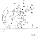
- the machine tool 10 is a face grinding machine, in particular one Double-sided surface grinding machine, with a working space 12, which extends between two grinding wheels, not shown, which process the active surfaces of workpieces 14 facing one another or their end faces 16 and 18 that face away from one another.
- a disc-shaped transport element 20 is provided for handling the workpieces 14 , which is driven to rotate about a vertical axis 24 by means of a first drive device 22 .
- the transport element 20 has a plurality of workpiece holders 26 which are designed in particular in the form of openings in the disc-shaped transport element 20 and each serve to hold a workpiece 14 .
- the workpiece holders 26 are preferably arranged regularly distributed along a pitch circle around the vertical axis 24 .
- a support surface 28 is provided in a manner known per se for supporting the workpieces 14 downwards, which is arranged below the transport element 20 .
- the loading device 32 In order to arrange the workpieces 14 in the workpiece receptacles 26, a loading device 32 discussed below is provided.
- the loading device 32 has a transport wheel 34 which is rotatably driven about a horizontal drive axis 36 by means of a second drive device 38, see figure 2 . It is preferred that the drive axis 36 is radially aligned with respect to the vertical axis 24 .
- the transport wheel 34 has a peripheral surface 38 .
- Workpiece holding areas 40 are provided distributed along the peripheral surface 38 .
- the workpiece holding areas preferably each extend along axes 42 which are radially aligned with respect to the drive axis 36 .
- the workpiece holding areas 40 have holding pins 44, which are preferably designed to be rotationally symmetrical with respect to the axis of extension 42, in particular truncated cone-shaped or cylindrical. Furthermore, the retaining pins 44 preferably each have a rounded portion 46 at their radially outward-pointing free end.
- the machine tool 10 includes a feed area, denoted overall by the reference numeral 48 , which is arranged adjacent to an upper area of the transport wheel 34 in relation to the drive axis 36 of the transport wheel 34 .
- the feed area 48 includes a slide ramp 50, shown in sections, which is arranged inclined relative to the horizontal, namely along a transport direction 51 seen in the direction of the transport wheel 34 downwards.
- the slide ramp 50 has lateral boundaries (not shown in the drawing), the distance between which is slightly greater than a maximum outer diameter of a workpiece 14.
- a supply 52 of a row of workpieces 14 arranged on the slide ramp 50 presses with its weight on the one furthest down arranged workpiece 14.
- the workpiece 14 arranged furthest below lies temporarily with an end face 16 on a support 54.
- the support 54 has a slit-shaped free space 56, into which the retaining pins 44 of the workpiece holding areas 40 of the transport wheel 34 can enter when rotating about the drive axis 36, into an annular space 58 bounded by a workpiece 14, so that rotation of the transport wheel 34 creates a workpiece 14 can be detected by the free end of a retaining pin 44 of a workpiece holding portion 40 and in a Transport direction 60 of the transport wheel 34 can be transported further along the circumference of the transport wheel 34.
- an intermediate part 62 is provided for the transition between the arrangement of a workpiece on the support 54 and an intermediate position in which a workpiece 14 comes to rest with an end face 16 on the peripheral surface 38 of the transport wheel 34 (cf figure 2 )
- this has a support surface 64 which is curved in an arc shape in the direction of the peripheral surface 38 and which supports a workpiece 14 during the transition between the support 54 and contact with the peripheral surface 38 .
- the intermediate element 62 also has a slit-shaped free space 66 which makes it possible for the holding pins 44 of the workpiece holding areas 40 to be guided through the intermediate part 62 without the components mentioned colliding.
- Loading transport wheel 34 can be assisted by arranging a hold-down device, for example a brush, above support 54 and/or intermediate part 62, which counteracts lifting of workpieces 14 from support 54 and/or from intermediate part 62.
- a hold-down device for example a brush
- the workpieces 14 are transferred along the transport direction 60 by moving the peripheral surface 38 and the workpiece holding areas 40 into a lower area of the transport wheel 34 in relation to the drive axis 36, which forms a release area designated overall by the reference numeral 68.
- a retaining device 70 is also effective, which extends radially outwards around the workpiece holding areas 40 of the transport wheel 34 in relation to the transport wheel 34 .
- the retaining pins 44 can sweep past a concavely curved contact surface 72 of the retaining device 70 without making contact, but a distance between the contact surface 72 and the free ends of the retaining pins 44 is selected such that it is smaller than the height of the workpieces 14, which is caused by the distance of the end faces 16 and 18 is determined.
- the distances between the workpiece holding areas 40 of the transport wheel 34 on the one hand and the distances between the workpiece holders 26 of the transport element 20 on the other hand are matched to one another.
- the vertical axis 24 of the transport element 20 is perpendicular to the horizontal drive axis 36 of the transport wheel 34 .
- the holding pins 44 of the workpiece holding areas 40 of the transport wheel 34 mesh with the workpiece receptacles 26 of the transport element 20.
- the drive devices 22 of the transport element 20 and 38 of the transport wheel 34 are synchronized with one another via a control device 74.
- the loading device 32 described above enables workpieces 14 to be loaded quickly and reliably into the workpiece receptacles 26 of the transport element 20.
- the transport wheel 34 could be loaded with three to four workpieces 14 per second.
Description
Die Erfindung betrifft eine Werkzeugmaschine, insbesondere Schleifmaschine, mit einem Arbeitsraum, in welchem ein in einem Transportelement aufgenommenes Werkstück bearbeitbar ist, wobei das Transportelement mehrere Werkstückaufnahmen zur Aufnahme von zu bearbeitenden Werkstücken aufweist, wobei ein jeweils in einer Werkstückaufnahme aufgenommenes Werkstück mittels des Transportelements in den Arbeitsraum hinein und aus dem Arbeitsraum heraus transportierbar ist, wobei eine Beladeeinrichtung vorgesehen ist, mittels welcher einzelne Werkstücke jeweils einer Werkstückaufnahme des Transportelements zuführbar sind. Eine Schleifmaschine mit den Merkmalen des Oberbegriffs des Patentanspruchs 1 ist aus der
Eine als Doppelseitenplanschleifmaschine ausgebildete Werkzeugmaschine ist aus der
Der vorliegenden Erfindung liegt die Aufgabe zugrunde, eine Werkzeugmaschine mit einer einfach aufgebauten Beladeeinrichtung zu schaffen, welche eine schnelle Beladung eines Transportelements ermöglicht.The present invention is based on the object of creating a machine tool with a simply constructed loading device, which enables rapid loading of a transport element.
Diese Aufgabe wird bei einer Werkzeugmaschine der eingangs genannten Art dadurch gelöst, dass die Beladeeinrichtung ein um eine Antriebsachse drehbares Transportrad umfasst, das entlang seines Umfangs verteilt angeordnete Werkstückhaltebereiche aufweist, welche bezogen auf die Antriebsachse in einer Richtung nach radial innen mit einzelnen Werkstücken bestückbar sind und welche bezogen auf die Antriebsachse in einer Richtung nach radial außen einzelne Werkstücke in jeweilige Werkstückaufnahmen des Transportelements freigeben.This object is achieved in a machine tool of the type mentioned at the outset in that the loading device comprises a transport wheel which can be rotated about a drive axis and which has workpiece holding areas distributed along its circumference, which can be fitted with individual workpieces in a radially inward direction relative to the drive axis and which release individual workpieces in respective workpiece holders of the transport element in a radially outward direction relative to the drive axis.
Das erfindungsgemäße Transportrad ermöglicht es, das Transportrad entlang seines Umfangs mit zueinander versetzt angeordneten Werkstücken zu bestücken und diese Werkstücke wieder freizugeben. Die Bestückung des Transportrads mit Werkstücken erfolgt bezogen auf die Antriebsachse des Transportrads in einer Richtung nach radial innen; die Freigabe erfolgt eines Werkstücks erfolgt in entgegengesetzter Richtung.The transport wheel according to the invention makes it possible to equip the transport wheel along its circumference with workpieces that are arranged offset relative to one another and to release these workpieces again. The transport wheel is loaded with workpieces in relation to the drive axle of the transport wheel in a radially inward direction; a workpiece is released in the opposite direction.
Die erfindungsgemäße Beladeeinrichtung ist relativ einfach aufgebaut und ermöglicht es durch eine vergleichsweise einfache Kinematik, nämlich durch das Drehen um die Antriebsachse des Transportrads, Werkstücke aus einem Zuführbereich in einen Freigabebereich zu überführen. Insbesondere ist es möglich, dass die Bestückung des Transportrads mit einem Werkstück und die Freigabe eines anderen Werkstücks gleichzeitig erfolgen.The loading device according to the invention has a relatively simple structure and allows workpieces to be transferred from a feed area to a release area by means of comparatively simple kinematics, namely by rotating about the drive axis of the transport wheel. In particular, it is possible for the transport wheel to be fitted with a workpiece and another workpiece to be released at the same time.
Die Beladeeinrichtung ermöglicht eine besonders zuverlässige, verkantungsfreie und schnelle Beladung auch von Werkstücken, welche an ihren Rändern noch Grate aufweisen.The loading device enables particularly reliable, tilt-free and fast loading, even of workpieces that still have burrs on their edges.
Vorzugsweise sind entlang des Umfangs des Transportrads mindestens zwei, insbesondere mindestens drei, insbesondere mindestens vier, insbesondere mindestens sechs, insbesondere mindestens acht Werkstückhaltebereiche angeordnet. Vorzugsweise sind die Werkstückhaltebereiche entlang des Umfangs des Transportrads gesehen zueinander äquidistant beabstandet.At least two, in particular at least three, in particular at least four, in particular at least six, in particular at least eight workpiece holding areas are preferably arranged along the circumference of the transport wheel. The workpiece holding areas are preferably spaced equidistantly from one another, as seen along the circumference of the transport wheel.
Eine bevorzugte Ausführungsform sieht vor, dass die Antriebsachse des Transportrads horizontal ausgerichtet ist. Hierunter wird nicht nur eine bezogen auf die Schwerkraftrichtung exakt horizontale Ausrichtung verstanden, sondern auch eine Ausrichtung, welche gegenüber dieser Horizontalen um maximal 20° geneigt ist. Die zumindest im Wesentlichen horizontale Ausrichtung der Antriebsachse hat den Vorteil, dass sich die Werkstückhaltebereiche des Transportrads in einem unteren Bereich des Transportrads tangential an einem zumindest im Wesentlichen horizontal ausgerichteten Transportelement vorbei bewegen können.A preferred embodiment provides that the drive axle of the transport wheel is aligned horizontally. This not only means an alignment that is exactly horizontal in relation to the direction of gravity, but also an alignment that is inclined by a maximum of 20° with respect to this horizontal. The at least essentially horizontal alignment of the drive axle has the advantage that the workpiece holding areas of the transport wheel can move tangentially past an at least essentially horizontally aligned transport element in a lower area of the transport wheel.
Vorzugsweise erstrecken sich die Werkstückhaltebereiche bezogen auf die Antriebsachse in radialer Richtung, was eine einfache Bestückung des Transportrads und eine einfache Freigabe der Werkstücke ermöglicht.The workpiece holding areas preferably extend in the radial direction in relation to the drive axis, which allows for easy loading of the transport wheel and easy release of the workpieces.
Grundsätzlich ist es möglich, dass ein Werkstück und ein Werkstückhaltebereich miteinander formschlüssig zusammenwirken. Zusätzlich oder alternativ hierzu ist es aber auch möglich, dass ein Werkstück über Magnetkräfte an oder in einem Werkstückhaltebereich gehalten ist.In principle, it is possible for a workpiece and a workpiece holding area to interact with one another in a form-fitting manner. In addition or as an alternative to this, however, it is also possible for a workpiece to be held on or in a workpiece holding area by means of magnetic forces.
Eine besonders vorteilhafte Ausführungsform sieht vor, dass die Werkstückhaltebereiche Haltestifte aufweisen. Diese ermöglichen insbesondere die Aufnahme ringförmiger Werkstücke, wobei die Haltestifte einen von dem Werkstück umschlossenen Ringraum durchdringen können (zur Bestückung des Transportrads), und wobei die Haltestifte auch wieder aus dem Ringraum des Werkstücks herausgeführt werden können (zur Freigabe des Werkstücks).A particularly advantageous embodiment provides that the workpiece holding areas have holding pins. In particular, these enable ring-shaped workpieces to be accommodated, with the retaining pins being able to penetrate an annular space enclosed by the workpiece (for loading of the transport wheel), and the retaining pins can also be guided out of the annular space of the workpiece again (to release the workpiece).
Es ist ferner bevorzugt, wenn eine erste Antriebseinrichtung zur Bewegung des Transportelements, eine zweite Antriebseinrichtung zur Drehung des Transportrads und eine Steuereinrichtung vorgesehen sind, wobei die Steuereinrichtung die beiden Antriebseinrichtungen derart steuert, dass eine Bewegung der Werkstückaufnahmen des Transportelements und eine Bewegung der Werkstückhaltebereiche des Transportrads miteinander synchronisiert sind. Für den Fall, dass die Werkstückhaltebereiche Haltestifte aufweisen, ist es bevorzugt, dass diese Haltestifte mit den Werkstückaufnahmen des Transportelements in einem kämmenden Eingriff stehen.It is also preferred if a first drive device for moving the transport element, a second drive device for rotating the transport wheel and a control device are provided, with the control device controlling the two drive devices in such a way that a movement of the workpiece holders of the transport element and a movement of the workpiece holding areas of the transport wheel are synchronized with each other. In the event that the workpiece holding areas have holding pins, it is preferred that these holding pins are in meshing engagement with the workpiece receptacles of the transport element.
Insbesondere ist es bevorzugt, wenn die erste Antriebseinrichtung eine Drehantriebseinrichtung zur Drehung des Transportelements um eine insbesondere vertikale Achse ist. Ein solches Transportelement ist insbesondere durch die Transportscheibe einer Schleifmaschine, insbesondere durch die Transportscheibe einer Doppelseitenplanschleifmaschine, gebildet.In particular, it is preferred if the first drive device is a rotary drive device for rotating the transport element about a vertical axis in particular. Such a transport element is formed in particular by the transport disc of a grinding machine, in particular by the transport disc of a double-sided face grinding machine.
Es ist ferner bevorzugt, wenn ein Zuführbereich zur Zuführung von Werkstücken vorgesehen ist, in welchem Werkstücke vereinzelt bereithaltbar und jeweils einem Werkstückhaltebereich zuführbar sind.It is also preferred if a feed area for feeding workpieces is provided, in which individual workpieces can be kept ready and can each be fed to a workpiece holding area.
Der Zuführbereich ist vorzugsweise benachbart zu einem oberen Bereich des Transportrads angeordnet. Mit einem "oberen Bereich des Transportrads" ist ein Bereich gemeint, welcher bei einer nicht vertikalen Orientierung der Antriebsachse des Transportrads bezogen auf die Schwerkraftrichtung weiter oben angeordnet ist als andere, weiter unten liegende Bereiche des Transportrads.The feed area is preferably arranged adjacent to an upper area of the transport wheel. An "upper area of the transport wheel" means an area which, when the drive axis of the transport wheel is not oriented vertically in relation to the direction of gravity, is arranged higher up than other areas of the transport wheel that are located further down.
Es wird ferner vorgeschlagen, dass der Zuführbereich eine Auflage zur Bereithaltung eines einzelnen Werkstücks aufweist. Dies ermöglicht es, dass die Werkstückhaltebereiche des Transportrads in den Bereich dieser Auflage hineinbewegt werden und auf diese Weise die an der Auflage bereitgehaltenen einzelnen Werkstücke erfassen und mitnehmen können.It is also proposed that the feed area has a support for holding an individual workpiece. This makes it possible for the workpiece holding areas of the transport wheel to be moved into the area of this support and in this way to grasp and take away the individual workpieces held ready on the support.
Sofern die Werkstückhaltebereich Haltestifte aufweisen, ist es bevorzugt, wenn die Auflage einen Freiraum oder Schlitz aufweist, der es ermöglicht, dass ein Haltestift durch die Auflage hindurch in einen Raum oberhalb der Auflage eintauchen kann, wobei diese Eintauchbewegung mit der Mitnahme eines insbesondere ringförmigen Werkstücks einhergeht.If the workpiece holding area has holding pins, it is preferred if the support has a free space or slot that allows a holding pin to penetrate through the support into a space above the support, with this immersion movement being accompanied by the entrainment of a workpiece, in particular a ring-shaped one .
Es ist ferner bevorzugt, wenn der Zuführbereich eine Rutschrampe zur Anordnung eines Vorrats von Werkstücken aufweist. Diese ermöglicht eine einfache Bevorratung von Werkstücken, welche schwerkraftbedingt auf der Rampe abrutschen, wobei das jeweils unterste Werkstück von dem nächsten freien Werkstückhaltebereich des Transportrads aufgenommen werden kann. Diese Art der Bevorratung von Werkstücken eignet sich besonders gut auch für Werkstücke, welche an ihren Rändern noch Grate aufweisen.It is also preferred if the feed area has a slip ramp for arranging a supply of workpieces. This allows easy storage of workpieces, which due to gravity slip down the ramp, with the bottom workpiece from the next free workpiece holding area of the transport wheel can be picked up. This type of storage of workpieces is particularly well suited for workpieces that still have burrs on their edges.
Vorzugsweise ist ein Freigabebereich zur Freigabe eines Werkstücks von einem unteren Bereich des Transportrads gebildet. Hiermit ist ein Bereich des Transportrads gemeint, welcher bei einer nicht vertikalen Ausrichtung der Antriebsachse des Transportrads in einem bezogen auf die Schwerkraftrichtung weiter unteren Bereich des Transportrads liegt als andere Bereiche des Transportrads. Die Anordnung des Freigabebereichs in einem unteren Bereich des Transportrads hat den Vorteil, dass eine Freigabe der Werkstücke schwerkraftunterstützt erfolgen kann. In diesem Zusammenhang ist es ferner vorteilhaft, dass in den Werkstückhaltebereichen gehaltene Werkstücke auf ihrem Weg zwischen dem Zuführbereich und dem Freigabebereich nicht nur durch die Schwerkraft unterstützt, sondern auch fliehkraftunterstützt in Richtung nach radial außen bewegt werden, was eine weitere Überführung in eine Werkstückaufnahme des Transportelements hinein unterstützt.A release area for releasing a workpiece is preferably formed from a lower area of the transport wheel. This means an area of the transport wheel which, when the drive axle of the transport wheel is not aligned vertically, is in an area of the transport wheel that is further lower than other areas of the transport wheel in relation to the direction of gravity. The arrangement of the release area in a lower area of the transport wheel has the advantage that the workpieces can be released with the aid of gravity. In this context, it is also advantageous that workpieces held in the workpiece holding areas are not only supported by gravity on their way between the feed area and the release area, but are also moved radially outwards with the aid of centrifugal force, which allows for a further transfer into a workpiece holder of the transport element supported into.
Um eine zuverlässige Überführung eines Werkstücks zwischen einem Zuführbereich und dem Freigabebereich zu ermöglichen, ist es bevorzugt, wenn eine Rückhalteeinrichtung vorgesehen ist, welche bezogen auf die Antriebsachse radial außerhalb der Werkstückaufnahmen angeordnet ist und sich insbesondere zwischen dem Zuführbereich und dem Freigabebereich erstreckt.In order to enable reliable transfer of a workpiece between a feed area and the release area, it is preferred if a retaining device is provided, which is arranged radially outside of the workpiece holders in relation to the drive axis and extends in particular between the feed area and the release area.
Eine bevorzugte Rückhalteeinrichtung weist eine konkav gekrümmte Anlagefläche auf, an welcher ein freizugebendes Werkstück zumindest in einem zu dem Freigabebereich benachbarten Bereich anliegt. Dies geht insbesondere einher mit einer Ausrichtung der Werkstücke in einer Lage, welcher einer Aufnahmelage innerhalb einer Werkstückaufnahme des Transportelements entspricht. In diesem Zusammenhang ist es bevorzugt, wenn ein Endabschnitt der Anlagefläche bezogen auf eine Aufnahmefläche des Transportelements tangential oder zumindest im Wesentlichen tangential ausgerichtet ist.A preferred retaining device has a concavely curved contact surface against which a workpiece to be released rests at least in an area adjacent to the release area. In particular, this is associated with an alignment of the workpieces in a position which corresponds to a receiving position within a workpiece receptacle of the transport element. In this context, it is preferred if an end section of the contact surface is aligned tangentially or at least essentially tangentially in relation to a receiving surface of the transport element.
Weitere Merkmale und Vorteile der Erfindung sind Gegenstand der nachfolgenden Beschreibung und der zeichnerischen Darstellung eines bevorzugten Ausführungsbeispiels.Further features and advantages of the invention are the subject of the following description and the graphic representation of a preferred exemplary embodiment.
In der Zeichnung zeigt
- Fig. 1
- Seitenansicht einer Ausführungsform einer Beladeeinrichtung; und
- Fig. 2
- eine perspektivische Ansicht der Beladeeinrichtung gemäß
Fig. 1 und eines Transportelements einer Werkzeugmaschine.
- 1
- Side view of an embodiment of a loading device; and
- 2
- a perspective view of the loading device according to FIG
1 and a transport element of a machine tool.
In der Zeichnung ist eine insgesamt mit dem Bezugszeichen 10 dargestellte Werkzeugmaschine mit jenen Teilen dargestellt, die für die vorliegende Erfindung relevant sind. Bei der Werkzeugmaschine 10 handelt es sich um eine Planschleifmaschine, insbesondere eine Doppelseitenplanschleifmaschine, mit einem Arbeitsraum 12, welcher sich zwischen zwei nicht dargestellten Schleifscheiben erstreckt, die miteinander zugewandten Wirkflächen Werkstücke 14 bzw. deren voneinander abgewandten Stirnflächen 16 und 18 schleifend bearbeiten.In the drawing, a machine tool, shown as a whole with the
Zur Handhabung der Werkstücke 14 ist ein scheibenförmiges Transportelement 20 vorgesehen, welches mittels einer ersten Antriebseinrichtung 22 um eine vertikale Achse 24 drehbar angetrieben ist. Das Transportelement 20 weist eine Mehrzahl von Werkstückaufnahmen 26 auf, welche insbesondere in Form von Durchbrechungen des scheibenförmigen Transportelements 20 ausgebildet sind und jeweils zur Aufnahme eines Werkstücks 14 dienen. Die Werkstückaufnahmen 26 sind vorzugsweise entlang eines Teilkreises um die vertikale Achse 24 regelmäßig verteilt angeordnet.A disc-
Bei Anordnung eines Werkstücks 14 in einer Werkstückaufnahme 26 ist das Werkstück 14 innerhalb des Arbeitsraums 12 zwischen den Wirkflächen der Schleifscheiben aufgenommen; in einem Bereich außerhalb des Arbeitsraums 12 ist zur Abstützung der Werkstücke 14 nach unten hin in an sich bekannter Weise eine Abstützfläche 28 vorgesehen, welche unterhalb des Transportelements 20 angeordnet ist.When a
Bei Drehung des Transportelements 20 um die vertikal Achse 24 bewegen sich einzelne Werkstücke 14, die jeweils in einer Werkstückaufnahme 26 aufgenommen sind, entlang einer (in diesem Fall gekrümmten) Transportrichtung 30 in den Arbeitsraum 12 hinein. Nach Bearbeitung innerhalb des Arbeitsraums 12 und unter Beibehaltung der Drehrichtung des Transportelements 20 werden schleifend bearbeitete Werkstücke 14 am Ende des Arbeitsraums 12 wieder aus diesem herausgeführt. Es ist möglich, dass die Werkstücke 14 durch kontinuierliche und weitere Drehung des Transportelements 20 mehrfach in den Arbeitsraum 12 hinein und aus diesem wieder herausgeführt werden.When the
Um die Werkstücke 14 in den Werkstückaufnahmen 26 anzuordnen, ist eine nachfolgend erörterte Beladeeinrichtung 32 vorgesehen. Die Beladeeinrichtung 32 weist ein Transportrad 34 auf, das um eine horizontale Antriebsachse 36 drehbar angetrieben ist, und zwar mittels einer zweiten Antriebseinrichtung 38, vergleiche
Das Transportrad 34 weist eine Umfangsfläche 38 auf. Entlang der Umfangsfläche 38 verteilt angeordnet sind Werkstückhaltebereiche 40 vorgesehen. Die Werkstückhaltebereich erstrecken sich vorzugsweise jeweils entlang Achsen 42, die bezogen auf die Antriebsachse 36 radial ausgerichtet sind.The
Die Werkstückhaltebereiche 40 weisen Haltestifte 44 auf, welche vorzugsweise bezogen auf die Erstreckungsachse 42 rotationssymmetrisch, insbesondere kegelstumpfförmig oder zylindrisch ausgebildet sind. Ferner weisen die Haltestifte 44 an ihren nach radial außen weisenden freien Ende vorzugsweise jeweils eine Abrundung 46 auf.The
Die Werkzeugmaschine 10 umfasst eine insgesamt mit dem Bezugszeichen 48 bezeichneten Zuführbereich, der bezogen auf die Antriebsachse 36 des Transportrads 34 benachbart zu einem oberen Bereich des Transportrads 34 angeordnet ist.The
Der Zuführbereich 48 umfasst eine abschnittsweise dargestellte Rutschrampe 50, welche relativ zu der Horizontalen geneigt angeordnet ist, und zwar entlang einer Transportrichtung 51 gesehen in Richtung auf das Transportrad 34 zu nach unten. Die Rutschrampe 50 weist in der Zeichnung nicht dargestellte seitliche Begrenzungen auf, deren Abstand zueinander etwas größer ist als ein maximaler Außendurchmesser eines Werkstücks 14. Ein auf der Rutschrampe 50 angeordneter Vorrat 52 einer Reihe von Werkstücken 14 drückt mit seinem Gewicht auf das jeweils am weitesten unten angeordnete Werkstück 14. Das am weitesten unten angeordnete Werkstück 14 liegt temporär mit einer Stirnfläche 16 auf einer Auflage 54 auf.The
Die Auflage 54 weist einen schlitzförmigen Freiraum 56 auf, in welchen hinein die Haltestifte 44 der Werkstückhaltebereiche 40 des Transportrads 34 bei Drehung um die Antriebsachse 36 hineintauchen können, in einen von einem Werkstück 14 umgrenzten Ringraum 58 hinein, sodass durch Drehung des Transportrads 34 ein Werkstück 14 von dem freien Ende eines Haltestifts 44 eines Werkstückhaltebereichs 40 erfasst werden kann und in einer Transportrichtung 60 des Transportrads 34 entlang des Umfangs des Transportrads 34 weitertransportiert werden kann.The
Für den Übergang zwischen der Anordnung eines Werkstücks auf der Auflage 54 und einer Zwischenlage, in welcher ein Werkstück 14 mit einer Stirnfläche 16 auf der Umfangsfläche 38 des Transportrads 34 zur Auflage kommt (vergleiche
Aus der vorstehenden Beschreibung ergibt sich, dass die Werkstücke 14 bezogen auf die Antriebsachse 36 des Transportrads 34 nach radial innen in Richtung der Werkstückhaltebereiche 40 zugeführt werden. Die Bestückung des Transportrads 34 kann dadurch unterstützt werden, dass oberhalb der Auflage 54 und/oder des Zwischenteils 62 ein Niederhalter, beispielsweise eine Bürste, angeordnet ist, welche einem Abheben der Werkstücke 14 von der Auflage 54 und/oder von dem Zwischenteil 62 entgegenwirkt.It follows from the above description that the
Ausgehend von dem Zuführbereich 48 werden die Werkstücke 14 entlang der Transportrichtung 60 durch Bewegung der Umfangsfläche 38 und der Werkstückhaltebereiche 40 in einen bezogen auf die Antriebsachse 36 unteren Bereich des Transportrads 34 überführt, der einen insgesamt mit dem Bezugszeichen 68 bezeichneten Freigabebereich bildet.Starting from the
In Transportrichtung der Werkstücke 14 zwischen Zuführbereich 48 und Freigabebereich 68 gesehen ist ferner eine Rückhalteeinrichtung 70 wirksam, welche sich bezogen auf das Transportrad 34 radial außen um die Werkstückhaltebereiche 40 des Transportrads 34 erstreckt. Die Haltestifte 44 können berührungslos an einer konkav gekrümmten Anlagefläche 72 der Rückhalteeinrichtung 70 vorbeistreichen, wobei aber ein Abstand zwischen der Anlagefläche 72 und den freien Enden der Haltestifte 44 so gewählt ist, dass dieser kleiner ist als eine Höhe der Werkstücke 14, welche durch den Abstand der Stirnflächen 16 und 18 bestimmt ist.Seen in the direction of transport of the
Im Zuge der Bewegung der Werkstücke 14 von ihrer Zwischenlage (Werkstück 14 liegt erstmalig mit Stirnfläche 16 an Umfangsfläche 38 des Transportrads 34 an) hin zu dem Freigabebereich 68 verlagern sich die Werkstücke 14 sowohl schwerkraftbedingt als auch fliehkraftbedingt in Richtung nach radial außen, bis sie in einem zu dem Freigabebereich 68 benachbarten Abschnitt der Rückhalteeinrichtung 70 auf der Anlagefläche 72 zur Anlage kommen. Dabei befindet sich ein freies Ende eines Haltestifts 44 aber immer noch in Eingriff mit dem Ringraum 58 des Werkstücks 14. Eine weitere Drehung des Transportrads 34 führt dann dazu, dass ein Werkstück 14 nach radial außen in eine sich ebenfalls bewegende Werkstückaufnahme 26 hinein freigegeben wird.In the course of the movement of the
Die Abstände der Werkstückhaltebereiche 40 des Transportrads 34 einerseits und die Abstände der Werkstückaufnahmen 26 des Transportelements 20 andererseits sind aufeinander abgestimmt. Die vertikale Achse 24 des Transportelements 20 ist senkrecht zu der horizontalen Antriebsachse 36 des Transportrads 34 ausgebildet. Dabei kämmen die Haltestifte 44 der Werkstückhaltebereiche 40 des Transportrads 34 mit den Werkstückaufnahmen 26 des Transportelements 20. Die Antriebseinrichtungen 22 des Transportelements 20 und 38 des Transportrads 34 sind über eine Steuereinrichtung 74 miteinander synchronisiert.The distances between the
Die vorstehend beschriebene Beladeeinrichtung 32 ermöglicht eine schnelle und zuverlässige Beladung von Werkstücken 14 in die Werkstückaufnahmen 26 des Transportelements 20. In der Praxis konnte das Transportrad 34 pro Sekunde mit drei bis vier Werkstücken 14 beladen werden.The
Claims (13)
- Machine tool (10), in particular a grinding machine, having a working space (12) in which a workpiece (14) received in a transport element (20) can be machined, the transport element (20) having a plurality of workpiece receptacles (26) for receiving workpieces (14) to be machined, wherein a workpiece (14) received in each workpiece receptacle (26) is transportable into and out of the working space (12) by means of the transport element (20), wherein a loading device (32) is provided by means of which individual workpieces (14) can each be fed to one workpiece receptacle (26) of the transport element (20), characterised in that the loading device (32) comprises a transport wheel (34) which can rotate about a drive axis (36) and has workpiece holding regions (40) which are arranged and distributed along the circumference of the transport wheel (34), wherein the workpiece holding regions (40) can be loaded with individual workpieces (14) in a radially inward direction relative to the drive axis (36) and which release individual workpieces (14) into respective workpiece receptacles (26) of the transport element (20) in a radially outward direction relative to the drive axis (36).
- Machine tool (10) according to claim 1, characterised in that the drive axis (36) of the transport wheel (34) is aligned horizontally.
- Machine tool (10) according to one of the preceding claims, characterised in that the workpiece holding regions (40) extend in a radial direction with respect to the drive axis (36).
- Machine tool (10) according to one of the preceding claims, characterised in that the workpiece holding regions (40) comprise holding pins (44).
- Machine tool (10) according to one of the preceding claims, characterised in that a first drive device (22) for moving the transport element (20), a second drive device (38) for rotating the transport wheel (34) and a control device (74) are provided, the control device (74) controlling the two drive devices (22, 38) in such a way that a movement of the workpiece receptacles (26) of the transport element (20) and a movement of the workpiece holding regions (40) of the transport wheel (34) are synchronized with one another.
- Machine tool (10) according to claim 5, characterised in that the first drive device (22) is a rotary drive device for rotating the transport element (20) about an axis (24), in particular about a vertical axis.
- Machine tool (10) according to one of the preceding claims, characterised in that a feed region (48) for feeding workpieces (14) is provided, in which workpieces (14) can be kept ready individually and can each be fed to one workpiece holding region (40).
- Machine tool (10) according to claim 7, characterised in that the feed region (48) is arranged adjacent to an upper region of the transport wheel (34).
- Machine tool (10) according to claim 7 or 8, characterised in that the feed area (48) comprises a support (54) for holding a single workpiece (14) ready.
- Machine tool (10) according to one of claims 7 to 9, characterised in that the feed region (48) comprises a slide ramp (50) for locating a supply (52) of workpieces (14).
- Machine tool (10) according to one of the preceding claims, characterised in that a release region (68) for releasing a workpiece (14) is formed by a lower region of the transport wheel (34).
- Machine tool (10) according to one of the preceding claims, characterised in that a retaining device (70) is provided, which is arranged radially outside the workpiece holders (40) with respect to the drive axis (36).
- Machine tool (10) according to claim 12, characterised in that the retaining device (70) has a concavely curved contact surface (72) against which a workpiece (14) to be released rests at least in a region adjacent to the release region (68) .
Applications Claiming Priority (1)
| Application Number | Priority Date | Filing Date | Title |
|---|---|---|---|
| PCT/EP2019/083545 WO2021110249A1 (en) | 2019-12-03 | 2019-12-03 | Machine tool, in particular grinding machine, having a loading device |
Publications (2)
| Publication Number | Publication Date |
|---|---|
| EP4034334A1 EP4034334A1 (en) | 2022-08-03 |
| EP4034334B1 true EP4034334B1 (en) | 2023-01-18 |
Family
ID=68808350
Family Applications (1)
| Application Number | Title | Priority Date | Filing Date |
|---|---|---|---|
| EP19816622.5A Active EP4034334B1 (en) | 2019-12-03 | 2019-12-03 | Machine tool, in particular grinding machine, having a loading device |
Country Status (2)
| Country | Link |
|---|---|
| EP (1) | EP4034334B1 (en) |
| WO (1) | WO2021110249A1 (en) |
Families Citing this family (1)
| Publication number | Priority date | Publication date | Assignee | Title |
|---|---|---|---|---|
| DE102022202512A1 (en) | 2022-03-14 | 2023-09-14 | Volkswagen Aktiengesellschaft | Turning system and method for turning a workpiece using this turning system |
Citations (3)
| Publication number | Priority date | Publication date | Assignee | Title |
|---|---|---|---|---|
| JPS5020294U (en) * | 1973-06-16 | 1975-03-07 | ||
| EP2260975A1 (en) * | 2009-06-10 | 2010-12-15 | Supfina Grieshaber GmbH & Co. KG | Surface grinding machine and method for processing workpieces with surface grinding |
| EP2301714B1 (en) * | 2009-09-23 | 2011-11-30 | Supfina Grieshaber GmbH & Co. KG | Surface grinding machine and method for operating and/or maintaining a surface grinding machine |
Family Cites Families (4)
| Publication number | Priority date | Publication date | Assignee | Title |
|---|---|---|---|---|
| DE3742953A1 (en) | 1987-12-18 | 1989-06-29 | Hahn & Kolb | Loading device for multiple workpiece holders |
| DE502008000963D1 (en) * | 2008-08-29 | 2010-08-26 | Supfina Grieshaber Gmbh & Co | Device for fine or ultra-fine machining of workpieces |
| CN103878652A (en) * | 2014-03-24 | 2014-06-25 | 乳山市宏远机床制造有限公司 | Special disk type feeding device of double-ended grinding machine |
| KR102039147B1 (en) * | 2019-03-20 | 2019-10-31 | (주)오성지엠 | Grinding component supply apparatus |
-
2019
- 2019-12-03 WO PCT/EP2019/083545 patent/WO2021110249A1/en unknown
- 2019-12-03 EP EP19816622.5A patent/EP4034334B1/en active Active
Patent Citations (3)
| Publication number | Priority date | Publication date | Assignee | Title |
|---|---|---|---|---|
| JPS5020294U (en) * | 1973-06-16 | 1975-03-07 | ||
| EP2260975A1 (en) * | 2009-06-10 | 2010-12-15 | Supfina Grieshaber GmbH & Co. KG | Surface grinding machine and method for processing workpieces with surface grinding |
| EP2301714B1 (en) * | 2009-09-23 | 2011-11-30 | Supfina Grieshaber GmbH & Co. KG | Surface grinding machine and method for operating and/or maintaining a surface grinding machine |
Also Published As
| Publication number | Publication date |
|---|---|
| EP4034334A1 (en) | 2022-08-03 |
| WO2021110249A1 (en) | 2021-06-10 |
Similar Documents
| Publication | Publication Date | Title |
|---|---|---|
| DE10061063B4 (en) | Method and device for feeding regular objects to a work station | |
| DE3624878A1 (en) | Flat lay machine | |
| DE3605470A1 (en) | MULTI-SURFACE MACHINE TOOL | |
| DE2510827C2 (en) | CONVEYOR DEVICE FOR CYLINDER BLOCKS OR SIMILAR WORKPIECES BY A SPIN BLASTING SYSTEM | |
| EP4034334B1 (en) | Machine tool, in particular grinding machine, having a loading device | |
| DE3247586A1 (en) | LATHE | |
| DD262829A5 (en) | TOOL MEMORY FOR MACHINE TOOLS AND METHOD FOR OPERATING THE SAME | |
| EP2260975B1 (en) | Surface grinding machine and method for processing workpieces with surface grinding | |
| EP1874667A1 (en) | Feeding device and method for feeding mechanical components | |
| DE4111545A1 (en) | Rotary indexing machine - has exchangeable workpiece holding fixtures on indexing table | |
| DE2828536A1 (en) | MACHINE TOOL | |
| EP1430992A1 (en) | Device for transferring flat workpieces with a linearly movable rotating arm | |
| DE4100148C2 (en) | ||
| EP0328958A2 (en) | Device for working rotation-symmetrical work piece surfaces | |
| DE2161575A1 (en) | Stacking device for packages | |
| DE3310535C2 (en) | ||
| DE4109877C2 (en) | ||
| DE484109C (en) | Device for feeding angular workpieces for machine tools | |
| DE2907282C2 (en) | Workpiece infeed and unloading device on machines for surface grinding | |
| DE2830923A1 (en) | DEVICE FOR PROMOTING THIN OBJECTS | |
| EP1255625B1 (en) | Device for machining circular saw blades | |
| DE410820C (en) | Device for milling threads on screws, in particular wood screws | |
| DE3723471A1 (en) | Machining device | |
| EP3294508B1 (en) | Workpiece feeding device and workpiece removing device | |
| DE19704200A1 (en) | Device for turning can bodies |
Legal Events
| Date | Code | Title | Description |
|---|---|---|---|
| STAA | Information on the status of an ep patent application or granted ep patent |
Free format text: STATUS: UNKNOWN |
|
| STAA | Information on the status of an ep patent application or granted ep patent |
Free format text: STATUS: THE INTERNATIONAL PUBLICATION HAS BEEN MADE |
|
| PUAI | Public reference made under article 153(3) epc to a published international application that has entered the european phase |
Free format text: ORIGINAL CODE: 0009012 |
|
| STAA | Information on the status of an ep patent application or granted ep patent |
Free format text: STATUS: REQUEST FOR EXAMINATION WAS MADE |
|
| 17P | Request for examination filed |
Effective date: 20220428 |
|
| AK | Designated contracting states |
Kind code of ref document: A1 Designated state(s): AL AT BE BG CH CY CZ DE DK EE ES FI FR GB GR HR HU IE IS IT LI LT LU LV MC MK MT NL NO PL PT RO RS SE SI SK SM TR |
|
| GRAP | Despatch of communication of intention to grant a patent |
Free format text: ORIGINAL CODE: EPIDOSNIGR1 |
|
| STAA | Information on the status of an ep patent application or granted ep patent |
Free format text: STATUS: GRANT OF PATENT IS INTENDED |
|
| DAV | Request for validation of the european patent (deleted) | ||
| DAX | Request for extension of the european patent (deleted) | ||
| INTG | Intention to grant announced |
Effective date: 20220908 |
|
| GRAS | Grant fee paid |
Free format text: ORIGINAL CODE: EPIDOSNIGR3 |
|
| GRAA | (expected) grant |
Free format text: ORIGINAL CODE: 0009210 |
|
| STAA | Information on the status of an ep patent application or granted ep patent |
Free format text: STATUS: THE PATENT HAS BEEN GRANTED |
|
| AK | Designated contracting states |
Kind code of ref document: B1 Designated state(s): AL AT BE BG CH CY CZ DE DK EE ES FI FR GB GR HR HU IE IS IT LI LT LU LV MC MK MT NL NO PL PT RO RS SE SI SK SM TR |
|
| REG | Reference to a national code |
Ref country code: GB Ref legal event code: FG4D Free format text: NOT ENGLISH |
|
| REG | Reference to a national code |
Ref country code: DE Ref legal event code: R096 Ref document number: 502019006852 Country of ref document: DE |
|
| REG | Reference to a national code |
Ref country code: CH Ref legal event code: EP |
|
| REG | Reference to a national code |
Ref country code: AT Ref legal event code: REF Ref document number: 1544417 Country of ref document: AT Kind code of ref document: T Effective date: 20230215 Ref country code: IE Ref legal event code: FG4D Free format text: LANGUAGE OF EP DOCUMENT: GERMAN |
|
| REG | Reference to a national code |
Ref country code: LT Ref legal event code: MG9D |
|
| REG | Reference to a national code |
Ref country code: NL Ref legal event code: MP Effective date: 20230118 |
|
| PG25 | Lapsed in a contracting state [announced via postgrant information from national office to epo] |
Ref country code: NL Free format text: LAPSE BECAUSE OF FAILURE TO SUBMIT A TRANSLATION OF THE DESCRIPTION OR TO PAY THE FEE WITHIN THE PRESCRIBED TIME-LIMIT Effective date: 20230118 |
|
| P01 | Opt-out of the competence of the unified patent court (upc) registered |
Effective date: 20230621 |
|
| PG25 | Lapsed in a contracting state [announced via postgrant information from national office to epo] |
Ref country code: RS Free format text: LAPSE BECAUSE OF FAILURE TO SUBMIT A TRANSLATION OF THE DESCRIPTION OR TO PAY THE FEE WITHIN THE PRESCRIBED TIME-LIMIT Effective date: 20230118 Ref country code: PT Free format text: LAPSE BECAUSE OF FAILURE TO SUBMIT A TRANSLATION OF THE DESCRIPTION OR TO PAY THE FEE WITHIN THE PRESCRIBED TIME-LIMIT Effective date: 20230518 Ref country code: NO Free format text: LAPSE BECAUSE OF FAILURE TO SUBMIT A TRANSLATION OF THE DESCRIPTION OR TO PAY THE FEE WITHIN THE PRESCRIBED TIME-LIMIT Effective date: 20230418 Ref country code: LV Free format text: LAPSE BECAUSE OF FAILURE TO SUBMIT A TRANSLATION OF THE DESCRIPTION OR TO PAY THE FEE WITHIN THE PRESCRIBED TIME-LIMIT Effective date: 20230118 Ref country code: LT Free format text: LAPSE BECAUSE OF FAILURE TO SUBMIT A TRANSLATION OF THE DESCRIPTION OR TO PAY THE FEE WITHIN THE PRESCRIBED TIME-LIMIT Effective date: 20230118 Ref country code: HR Free format text: LAPSE BECAUSE OF FAILURE TO SUBMIT A TRANSLATION OF THE DESCRIPTION OR TO PAY THE FEE WITHIN THE PRESCRIBED TIME-LIMIT Effective date: 20230118 Ref country code: ES Free format text: LAPSE BECAUSE OF FAILURE TO SUBMIT A TRANSLATION OF THE DESCRIPTION OR TO PAY THE FEE WITHIN THE PRESCRIBED TIME-LIMIT Effective date: 20230118 |
|
| PG25 | Lapsed in a contracting state [announced via postgrant information from national office to epo] |
Ref country code: SE Free format text: LAPSE BECAUSE OF FAILURE TO SUBMIT A TRANSLATION OF THE DESCRIPTION OR TO PAY THE FEE WITHIN THE PRESCRIBED TIME-LIMIT Effective date: 20230118 Ref country code: PL Free format text: LAPSE BECAUSE OF FAILURE TO SUBMIT A TRANSLATION OF THE DESCRIPTION OR TO PAY THE FEE WITHIN THE PRESCRIBED TIME-LIMIT Effective date: 20230118 Ref country code: IS Free format text: LAPSE BECAUSE OF FAILURE TO SUBMIT A TRANSLATION OF THE DESCRIPTION OR TO PAY THE FEE WITHIN THE PRESCRIBED TIME-LIMIT Effective date: 20230518 Ref country code: GR Free format text: LAPSE BECAUSE OF FAILURE TO SUBMIT A TRANSLATION OF THE DESCRIPTION OR TO PAY THE FEE WITHIN THE PRESCRIBED TIME-LIMIT Effective date: 20230419 Ref country code: FI Free format text: LAPSE BECAUSE OF FAILURE TO SUBMIT A TRANSLATION OF THE DESCRIPTION OR TO PAY THE FEE WITHIN THE PRESCRIBED TIME-LIMIT Effective date: 20230118 |
|
| REG | Reference to a national code |
Ref country code: DE Ref legal event code: R097 Ref document number: 502019006852 Country of ref document: DE |
|
| PG25 | Lapsed in a contracting state [announced via postgrant information from national office to epo] |
Ref country code: SM Free format text: LAPSE BECAUSE OF FAILURE TO SUBMIT A TRANSLATION OF THE DESCRIPTION OR TO PAY THE FEE WITHIN THE PRESCRIBED TIME-LIMIT Effective date: 20230118 Ref country code: RO Free format text: LAPSE BECAUSE OF FAILURE TO SUBMIT A TRANSLATION OF THE DESCRIPTION OR TO PAY THE FEE WITHIN THE PRESCRIBED TIME-LIMIT Effective date: 20230118 Ref country code: EE Free format text: LAPSE BECAUSE OF FAILURE TO SUBMIT A TRANSLATION OF THE DESCRIPTION OR TO PAY THE FEE WITHIN THE PRESCRIBED TIME-LIMIT Effective date: 20230118 Ref country code: DK Free format text: LAPSE BECAUSE OF FAILURE TO SUBMIT A TRANSLATION OF THE DESCRIPTION OR TO PAY THE FEE WITHIN THE PRESCRIBED TIME-LIMIT Effective date: 20230118 Ref country code: CZ Free format text: LAPSE BECAUSE OF FAILURE TO SUBMIT A TRANSLATION OF THE DESCRIPTION OR TO PAY THE FEE WITHIN THE PRESCRIBED TIME-LIMIT Effective date: 20230118 |
|
| PLBE | No opposition filed within time limit |
Free format text: ORIGINAL CODE: 0009261 |
|
| STAA | Information on the status of an ep patent application or granted ep patent |
Free format text: STATUS: NO OPPOSITION FILED WITHIN TIME LIMIT |
|
| PG25 | Lapsed in a contracting state [announced via postgrant information from national office to epo] |
Ref country code: SK Free format text: LAPSE BECAUSE OF FAILURE TO SUBMIT A TRANSLATION OF THE DESCRIPTION OR TO PAY THE FEE WITHIN THE PRESCRIBED TIME-LIMIT Effective date: 20230118 |
|
| 26N | No opposition filed |
Effective date: 20231019 |
|
| PG25 | Lapsed in a contracting state [announced via postgrant information from national office to epo] |
Ref country code: SI Free format text: LAPSE BECAUSE OF FAILURE TO SUBMIT A TRANSLATION OF THE DESCRIPTION OR TO PAY THE FEE WITHIN THE PRESCRIBED TIME-LIMIT Effective date: 20230118 |
|
| PGFP | Annual fee paid to national office [announced via postgrant information from national office to epo] |
Ref country code: FR Payment date: 20231219 Year of fee payment: 5 Ref country code: DE Payment date: 20231214 Year of fee payment: 5 |