EP0328958A2 - Device for working rotation-symmetrical work piece surfaces - Google Patents
Device for working rotation-symmetrical work piece surfaces Download PDFInfo
- Publication number
- EP0328958A2 EP0328958A2 EP89101856A EP89101856A EP0328958A2 EP 0328958 A2 EP0328958 A2 EP 0328958A2 EP 89101856 A EP89101856 A EP 89101856A EP 89101856 A EP89101856 A EP 89101856A EP 0328958 A2 EP0328958 A2 EP 0328958A2
- Authority
- EP
- European Patent Office
- Prior art keywords
- tools
- tool
- spindle
- another
- rotationally symmetrical
- Prior art date
- Legal status (The legal status is an assumption and is not a legal conclusion. Google has not performed a legal analysis and makes no representation as to the accuracy of the status listed.)
- Granted
Links
Images


Classifications
-
- B—PERFORMING OPERATIONS; TRANSPORTING
- B23—MACHINE TOOLS; METAL-WORKING NOT OTHERWISE PROVIDED FOR
- B23D—PLANING; SLOTTING; SHEARING; BROACHING; SAWING; FILING; SCRAPING; LIKE OPERATIONS FOR WORKING METAL BY REMOVING MATERIAL, NOT OTHERWISE PROVIDED FOR
- B23D37/00—Broaching machines or broaching devices
- B23D37/005—Broaching machines or broaching devices for cylindrical workpieces, e.g. crankshafts
-
- Y—GENERAL TAGGING OF NEW TECHNOLOGICAL DEVELOPMENTS; GENERAL TAGGING OF CROSS-SECTIONAL TECHNOLOGIES SPANNING OVER SEVERAL SECTIONS OF THE IPC; TECHNICAL SUBJECTS COVERED BY FORMER USPC CROSS-REFERENCE ART COLLECTIONS [XRACs] AND DIGESTS
- Y10—TECHNICAL SUBJECTS COVERED BY FORMER USPC
- Y10T—TECHNICAL SUBJECTS COVERED BY FORMER US CLASSIFICATION
- Y10T29/00—Metal working
- Y10T29/51—Plural diverse manufacturing apparatus including means for metal shaping or assembling
- Y10T29/5104—Type of machine
- Y10T29/5109—Lathe
- Y10T29/5114—Lathe and tool
-
- Y—GENERAL TAGGING OF NEW TECHNOLOGICAL DEVELOPMENTS; GENERAL TAGGING OF CROSS-SECTIONAL TECHNOLOGIES SPANNING OVER SEVERAL SECTIONS OF THE IPC; TECHNICAL SUBJECTS COVERED BY FORMER USPC CROSS-REFERENCE ART COLLECTIONS [XRACs] AND DIGESTS
- Y10—TECHNICAL SUBJECTS COVERED BY FORMER USPC
- Y10T—TECHNICAL SUBJECTS COVERED BY FORMER US CLASSIFICATION
- Y10T409/00—Gear cutting, milling, or planing
- Y10T409/30—Milling
- Y10T409/306664—Milling including means to infeed rotary cutter toward work
- Y10T409/30756—Machining arcuate surface
-
- Y—GENERAL TAGGING OF NEW TECHNOLOGICAL DEVELOPMENTS; GENERAL TAGGING OF CROSS-SECTIONAL TECHNOLOGIES SPANNING OVER SEVERAL SECTIONS OF THE IPC; TECHNICAL SUBJECTS COVERED BY FORMER USPC CROSS-REFERENCE ART COLLECTIONS [XRACs] AND DIGESTS
- Y10—TECHNICAL SUBJECTS COVERED BY FORMER USPC
- Y10T—TECHNICAL SUBJECTS COVERED BY FORMER US CLASSIFICATION
- Y10T409/00—Gear cutting, milling, or planing
- Y10T409/30—Milling
- Y10T409/309352—Cutter spindle or spindle support
- Y10T409/309408—Cutter spindle or spindle support with cutter holder
-
- Y—GENERAL TAGGING OF NEW TECHNOLOGICAL DEVELOPMENTS; GENERAL TAGGING OF CROSS-SECTIONAL TECHNOLOGIES SPANNING OVER SEVERAL SECTIONS OF THE IPC; TECHNICAL SUBJECTS COVERED BY FORMER USPC CROSS-REFERENCE ART COLLECTIONS [XRACs] AND DIGESTS
- Y10—TECHNICAL SUBJECTS COVERED BY FORMER USPC
- Y10T—TECHNICAL SUBJECTS COVERED BY FORMER US CLASSIFICATION
- Y10T409/00—Gear cutting, milling, or planing
- Y10T409/30—Milling
- Y10T409/309576—Machine frame
- Y10T409/309632—Overarm harness structure
-
- Y—GENERAL TAGGING OF NEW TECHNOLOGICAL DEVELOPMENTS; GENERAL TAGGING OF CROSS-SECTIONAL TECHNOLOGIES SPANNING OVER SEVERAL SECTIONS OF THE IPC; TECHNICAL SUBJECTS COVERED BY FORMER USPC CROSS-REFERENCE ART COLLECTIONS [XRACs] AND DIGESTS
- Y10—TECHNICAL SUBJECTS COVERED BY FORMER USPC
- Y10T—TECHNICAL SUBJECTS COVERED BY FORMER US CLASSIFICATION
- Y10T409/00—Gear cutting, milling, or planing
- Y10T409/40—Broaching
- Y10T409/404375—Broaching with plural cutters
-
- Y—GENERAL TAGGING OF NEW TECHNOLOGICAL DEVELOPMENTS; GENERAL TAGGING OF CROSS-SECTIONAL TECHNOLOGIES SPANNING OVER SEVERAL SECTIONS OF THE IPC; TECHNICAL SUBJECTS COVERED BY FORMER USPC CROSS-REFERENCE ART COLLECTIONS [XRACs] AND DIGESTS
- Y10—TECHNICAL SUBJECTS COVERED BY FORMER USPC
- Y10T—TECHNICAL SUBJECTS COVERED BY FORMER US CLASSIFICATION
- Y10T409/00—Gear cutting, milling, or planing
- Y10T409/40—Broaching
- Y10T409/4077—Cutter support or guide
-
- Y—GENERAL TAGGING OF NEW TECHNOLOGICAL DEVELOPMENTS; GENERAL TAGGING OF CROSS-SECTIONAL TECHNOLOGIES SPANNING OVER SEVERAL SECTIONS OF THE IPC; TECHNICAL SUBJECTS COVERED BY FORMER USPC CROSS-REFERENCE ART COLLECTIONS [XRACs] AND DIGESTS
- Y10—TECHNICAL SUBJECTS COVERED BY FORMER USPC
- Y10T—TECHNICAL SUBJECTS COVERED BY FORMER US CLASSIFICATION
- Y10T483/00—Tool changing
- Y10T483/17—Tool changing including machine tool or component
- Y10T483/1702—Rotating work machine tool [e.g., screw machine, lathe, etc.]
- Y10T483/1707—Tool having specific mounting or work treating feature
-
- Y—GENERAL TAGGING OF NEW TECHNOLOGICAL DEVELOPMENTS; GENERAL TAGGING OF CROSS-SECTIONAL TECHNOLOGIES SPANNING OVER SEVERAL SECTIONS OF THE IPC; TECHNICAL SUBJECTS COVERED BY FORMER USPC CROSS-REFERENCE ART COLLECTIONS [XRACs] AND DIGESTS
- Y10—TECHNICAL SUBJECTS COVERED BY FORMER USPC
- Y10T—TECHNICAL SUBJECTS COVERED BY FORMER US CLASSIFICATION
- Y10T483/00—Tool changing
- Y10T483/17—Tool changing including machine tool or component
- Y10T483/1733—Rotary spindle machine tool [e.g., milling machine, boring, machine, grinding machine, etc.]
- Y10T483/1736—Tool having specific mounting or work treating feature
Definitions
- the invention relates to a device for machining rotationally symmetrical workpiece surfaces according to the preamble of claim 1.
- the two set tools 4, 5 are advantageously turned in the same direction and at the same speed. However, it is of course also possible to drive the two set tools at different speeds and / or in opposite directions.
- the set tool 4 has a mandrel 8 projecting axially over the last individual tool 4 ⁇ , which has a circular cross section and engages in a corresponding central recess 9 of the other set tool 5.
- the two set tools 4, 5 are supported against each other as a result of this design, so that no additional bearings are required for support.
- the device has a structurally simple structure. Since no additional bearings are necessary, the set tools 4, 5 can be replaced quickly and, if necessary, automatically.
- the tool spindle 10 has a central through opening 12 (FIG. 2), in which a clamping device 13 for the tool 4 is accommodated in a known manner.
- the clamping device 13 has collets 14 which can be adjusted from a release position into a clamping position by means of a clamping rod 15 which is axially displaceable in the through opening 12.
- the collets 14 grip in the clamping position (Fig. 2) a pull stud 16 which is provided with a collar at its free end. It is engaged by the free ends of the collets 14 in a known manner.
- the tool 4 is pulled against the spindle 10 via the pull stud 16 in such a way that it lies flat against the end face 18.
- the tool 4 is provided with a short cone 17 which engages in a conical receptacle of the spindle 10.
- the locking bodies 29 are designed as pistons acted upon on one side, each of which has a tooth 31 engaging in the external toothing 28 on its end side facing the spindle 10.
- the locking bodies 29 are located in the cylinder 30, which run radially to the spindle 10 and are closed off from the outside in the housing 30.
- a pressure medium line 33 opens into them, through which the pressure medium serving to act on the locking bodies 29 is guided into the cylinder spaces 32. All pressure medium lines 33 are connected to a common supply line 34.
- the spindle 11 can be locked in the same way with such locking bodies with the headstock 7.
- the locking body 29 is only relieved.
- the relieved locking bodies are then pushed back into the cylinder spaces 32.
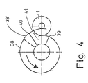
- Fig. 4 shows an embodiment of the individual tools of the set tools 4, 5.
- the individual tool is provided with a spiral-shaped cutting edge arrangement 38. It extends over an angular range of approximately 330 °. With the cutting portion 38 ', as will be explained below, undercuts in the crankshaft 1 are produced.
- the tool is provided with a sector-shaped cutout 41 between the starting point 39 and the end point 40 of the cutting edge arrangement 38.
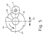
- the individual tool of each set tool 4, 5 can also have a plurality of cutting edge sections 42 to 45 (FIG. 5), in which the cutting edges can be arranged spirally. It is therefore divided into individual segments.
- the crankshaft 1 can be machined using the rotary broaching method, the tool only rotating about its axis, but does not have to be fed to the crankshaft due to the spiral cutting sections 42 to 44.
- the crankshaft 1 can also be machined using the turning method. But the tool must Machining to be delivered to the crankshaft (arrow 46).
- the cutting section 45 which is shorter in the exemplary embodiment than the cutting sections 42 to 44, undercuts are also produced in the turning process. This individual tool in turn has a sector-shaped cutout 47.
- the tools described can also be used for turning.
- the respective Tool locked via the spindle 10 or 11 with the locking bodies 29 against rotation, as has been described with reference to FIG. 3.
- the crankshaft 1 is rotated about the axis of the bearings.
- undercuts 50 can also be produced on the crankshaft 1.
- at least one of the individual tools 4 ', 4 ⁇ or 5' to 5 ′′′ of the set tools 4, 5 is provided with a corresponding cutting edge arrangement. 4
- the cutting section 38 ' is provided for this purpose, while the cutting section 45 is used for this in the tool according to FIG. 5.
- the remaining individual tools of the set tools 4, 5, which are not required for the production of such back stitches, do not have the cutting section 38 'or 45. Accordingly, the sector-shaped cutouts 41 and 47 of these individual tools extend into this area (dashed line in FIGS. 4 and 5).
- the set tools 4, 5 can be easily installed in the device and also removed from it. As has been explained with reference to FIG. 2, the set tools 4 can be fastened to the respective spindle 10, 11 by means of the pull bolts 16. To remove the set tools 4, 5, the clamping devices are pushed axially forward in the spindles 10, 11 in a known manner, so that the collets 14 can release the pull stud 14. With this axial displacement, the pull stud and thus also the respective set tool 4, 5 are expediently pushed slightly axially relative to the spindle 10 or 11. By loosening the clamping device 13, the setting tool 4 or 5 is thus axially displaced so far that its short cone 17 (FIGS. 1 and 2) is released from the corresponding receptacle of the spindle 10, 11.
- the set tools are then displaced axially towards one another by means of a gripping device 51 until the set tools are completely free of the spindles 10, 11.
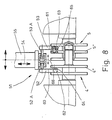
- the gripping device 51 (FIG. 8) has two gripping arms 52 and 53 which are displaceable relative to one another and which are provided on a carrier 55 which can be adjusted transversely to the setting tools 4, 5 in the direction of the arrow 54.
- the gripping arms 52, 53 can be displaced in the direction of arrow 66 via piston-cylinder arrangements 52A, 53A.
- the gripping device 51 is fed in the direction of the arrow 54 to the setting tools 4, 5 such that the gripping arms 52, 53 can move in unhindered between the individual tools of the two setting tools.
- the gripping arms 52, 53 are adjusted to each other so that they rest on the individual tools 4 ⁇ and 5 ⁇ in the exemplary embodiment. By moving the gripping arms 52, 53, the set tools 4, 5 can then be completely released from the spindles 10, 11.
- the gripping arms 52, 53 are provided near their free ends on their mutually facing sides 60 and 61 with vertically projecting, preferably hydraulically displaceable bolts 62 and 63 which engage in the position described in bores 64 and 65 in the individual tools 4 ⁇ , 5 ⁇ .
- the gripping device 51 is then moved back, taking the two set tools 4, 5 with it.
- Loaders, cranes or other lifting devices can be used as carriers for the gripping device 51.
Landscapes
- Engineering & Computer Science (AREA)
- Mechanical Engineering (AREA)
- Turning (AREA)
- Constituent Portions Of Griding Lathes, Driving, Sensing And Control (AREA)
- Grinding Of Cylindrical And Plane Surfaces (AREA)
Abstract
Description
Die Erfindung betrifft eine Vorrichtung zum Bearbeiten von rotationssymmetrischen Werkstückflächen nach dem Oberbegriff des Anspruches 1.The invention relates to a device for machining rotationally symmetrical workpiece surfaces according to the preamble of
Bei bekannten Vorrichtungen dieser Art lassen sich die Werkzeuge nur mit großem Aufwand ein- und ausbauen. Hierbei sind erhebliche manuelle Operationen notwendig, die zu großen Stillstandszeiten der Vorrichtung führen.In known devices of this type, the tools can only be installed and removed with great effort. This requires considerable manual operations, which lead to long downtimes of the device.
Der Erfindung liegt die Aufgabe zugrunde, die gattungsgemäße Vorrichtung so auszubilden, daß die Werkzeuge schnell und automatisch ein- und ausgebaut werden können.The invention has for its object to design the generic device so that the tools can be quickly and automatically installed and removed.
Diese Aufgabe wird bei der gattungsgemäßen Vorrichtung erfindungsgemäß mit den kennzeichnenden Merkmalen des Anspruches 1 gelöst.This object is achieved according to the invention in the generic device with the characterizing features of
Da die Werkzeuge der erfindungsgemäßen Vorrichtung axial relativ zueinander verstellbar sind, lassen sie sich mit einer geeigneten Ladeeinrichtung schnell und automatisch austauschen. Die Werkzeuge werden zum Ausbau so weit zusammengeschoben, daß sie von den Spindeln freikommen und der Vorrichtung automatisch entnommen werden können. Zum Einbau lassen sich die Werkzeuge dann entsprechend axial auseinanderfahren. Die Stillstandszeiten beim Austausch der Werkzeuge können somit sehr gering gehalten werden.Since the tools of the device according to the invention are axially adjustable relative to one another, they can be exchanged quickly and automatically with a suitable charging device. The tools are pushed together for removal so far that they come free from the spindles and can be removed from the device automatically. The tools can then be moved apart axially for installation. The downtimes when replacing the tools can thus be kept very low.
Weitere Merkmale der Erfindung ergeben sich aus den weiteren Ansprüchen, der Beschreibung und den Zeichnungen.Further features of the invention result from the further claims, the description and the drawings.
Die Erfindung wird anhand einiger in den Zeichnungen dargestellter Ausführungsformen näher erläutert. Es zeigen
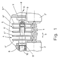
- Fig. 1 in schematischer Darstellung eine erfindungsgemäße Vorrichtung, in die eine zu bearbeitende Kurbelwelle eingespannt ist,
- Fig. 2 in vergrößerter Darstellung und im Schnitt die Einspannung eines Werkzeuges der erfindungsgemäßen Vorrichtung,
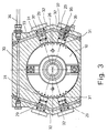
- Fig. 3 einen Schnitt längs der Linie III-III in Fig. 2,
- Fig. 4 in schematischer Darstellung und in Seitenansicht ein Werkzeug der erfindungsgemäßen Vorrichtung, mit dem eine Kurbelwelle bearbeitet wird,
- Fig. 5 eine zweite Ausführungsform eines Werkzeuges der erfindungsgemäßen Vorrichtung in einer Darstellung entsprechend Fig. 4,
- Fig. 6 einen mit der erfindungsgemäßen Vorrichtung hergestellten Einstich in einer Kurbelwelle,
- Fig. 7 einen mit der erfindungsgemäßen Vorrichtung hergestellten Einstich und Hinterstich in einer Kurbelwelle,
- Fig. 8 in schematischer Darstellung einen Teil einer Ladeeinrichtung der erfindungsgemäßen Vorrichtung.
- 1 is a schematic representation of a device according to the invention, in which a crankshaft to be machined is clamped,
- 2 in an enlarged representation and in section the clamping of a tool of the device according to the invention,
- 3 shows a section along the line III-III in FIG. 2,
- 4 is a schematic representation and a side view of a tool of the device according to the invention, with which a crankshaft is processed,
- 5 shows a second embodiment of a tool of the device according to the invention in a representation corresponding to FIG. 4,
- 6 shows a recess in a crankshaft produced with the device according to the invention,
- 7 shows a stitch and backstitch produced with the device according to the invention in one Crankshaft,
- Fig. 8 shows a schematic representation of part of a charging device of the device according to the invention.
Die nachfolgend beschriebene Vorrichtung dient zum Bearbeiten von Kurbelwellen, Stangen, Nockenwellen, Getriebewellen und dgl. Im folgenden wird die Vorrichtung anhand der Bearbeitung einer Kurbelwelle erläutert.The device described below is used for machining crankshafts, rods, camshafts, gear shafts and the like. The device is explained below with the aid of machining a crankshaft.
Fig. 1 zeigt eine Vorrichtung, in der die zu bearbeitende Kurbelwelle 1 an ihren beiden Enden in bekannter Weise in Spannstöcken 2, 2′ drehbar eingespannt ist. Während der Bearbeitung dreht die Kurbelwelle um die Achse der gerade zu bearbeitenden Lager. Die Spannstöcke 2, 2′ sind in bekannter Weise jeweils in Pfeilrichtung 3 verstellbar.Fig. 1 shows a device in which the
Zur Bearbeitung der Lager der Kurbelwelle 1 sowie auch zur Bearbeitung ihrer Seitenwangen ist die Vorrichtung mit zwei Satzwerkzeugen 4 und 5 versehen, die im Dreh- und im Drehräumverfahren eingesetzt werden. Im Ausführungsbeispiel hat das Satzwerkzeug 4 zwei Einzelwerkzeuge 4′, 4˝ und das Satzwerkzeug 5 drei Einzelwerkzeuge 5′ bis 5‴. Die Satzwerkzeuge 4 und 5 können vorzugsweise unabhängig voneinander drehbar angetrieben werden. Die Spindelstöcke 6, 7 der Satzwerkzeuge 4, 5 sind in Achsrichtung sowie in Richtung auf das Werkstück verstellbar.For machining the bearings of the
Die Satzwerkzeuge 4, 5 sind so ausgebildet, daß ihre Einzelwerkzeuge 4′, 4˝, 5′ bis 5‴ gleichzeitig eine Bearbeitung an der Kurbelwelle durchführen. Im Ausführungsbeispiel gemäß Fig. 1 bearbeiten die Einzelwerkzeuge die Hauptlager der Kurbelwelle 1.The
Beim Drehräumverfahren werden die beiden Satzwerkzeuge 4, 5 vorteilhaft gleichsinnig und mit gleicher Geschwindigkeit gedreht. Es ist aber selbstverständlich auch möglich, die beiden Satzwerkzeuge mit unterschiedlichen Geschwindigkeiten und/oder gegensinnig anzutreiben.In the rotary broaching method, the two
Das Satzwerkzeug 4 hat einen über das letzte Einzelwerkzeug 4˝ axial ragenden Dorn 8, der kreisförmigen Querschnitt hat und in eine entsprechende zentrische Vertiefung 9 des anderen Satzwerkzeuges 5 eingreift. Die beiden Satzwerkzeuge 4, 5 stützen sich infolge dieser Ausbildung aneinander ab, so daß keine zusätzlichen Lager zur Abstützung erforderlich sind. Dadurch hat die Vorrichtung einen konstruktiv einfachen Aufbau. Da keine zusätzlichen Lager notwendig sind, lassen sich die Satzwerkzeuge 4, 5 schnell und gegebenenfalls automatisch austauschen.The
Die Werkzeugspindel 10 weist eine zentrale Durchgangsöffnung 12 auf (Fig. 2), in der in bekannter Weise eine Spanneinrichtung 13 für das Werkzeug 4 untergebracht ist. Die Spanneinrichtung 13 hat Spannzangen 14, die durch eine in der Durchgangsöffnung 12 axial verschiebbare Spannstange 15 aus einer Freigabe- in eine Spannstellung verstellt werden können. Die Spannzangen 14 ergreifen in der Spannstellung (Fig. 2) einen Anzugsbolzen 16, der an seinem freien Ende mit einem Bund versehen ist. Er wird von den freien Enden der Spannzangen 14 in bekannter Weise hintergriffen. Über den Anzugsbolzen 16 wird das Werkzeug 4 so gegen die Spindel 10 gezogen, daß es an der Stirnseite 18 plan anliegt. Zur Zentrierung ist das Werkzeug 4 mit einem Kurzkegel 17 versehen, der in eine kegelförmige Aufnahme der Spindel 10 eingreift.The
Mit den Satzwerkzeugen 4, 5 kann das Werkstück sowohl im Drehräumverfahren als auch im Drehverfahren bearbeitet werden. Bei der Bearbeitung im Drehverfahren wird das Satzwerkzeug 4 bzw. 5 gegenüber dem Spindelstock 6 bzw. 7 verriegelt. Dies wird für das Werkzeug 4 anhand der Fig. 2 und 3 näher erläutert. Die Spindel 10 ist mit einer Außenverzahnung 28 versehen (Fig. 3), in die wenigstens ein Verriegelungskörper 29 eingreift, der im Gehäuse 30 des Spindelstockes 6 untergebracht ist. Um auch bei hohen Belastungen während der Drehbearbeitung eine einwandfreie und sichere Verriegelung zu erreichen, sind im Gehäuse 30 bevorzugt mehrere Verriegelungskörper 29, im Ausführungsbeispiel vier Verriegelungskörper untergebracht, von denen jeweils zwei diametral einander gegenüberliegend angeordnet sind. Die Verriegelungskörper 29 sind als einseitig beaufschlagte Kolben ausgebildet, die an ihrer der Spindel 10 zugewandten Stirnseite mit jeweils einem in die Außenverzahnung 28 eingreifenden Zahn 31 versehen sind. Die Verriegelungskörper 29 liegen in radial zur Spindel 10 verlaufenden und nach außen abgeschlossenen Zylinderräumen 32 im Gehäuse 30. In sie mündet jeweils eine Druckmittelleitung 33, durch die das zur Beaufschlagung der Verriegelungskörper 29 dienende Druckmittel in die Zylinderräume 32 geführt wird. Sämtliche Druckmittelleitungen 33 sind an eine gemeinsame Zuführleitung 34 angeschlossen.With the
Die Spindel 11 kann in gleicher Weise mit solchen Verriegelungskörpern mit dem Spindelstock 7 verriegelt werden.The
Um die Verriegelungskörper 29 in den Zylinderräumen 32 zuverlässig gegen Verdrehen zu sichern, sind die Verriegelungskörper an ihrer vom Zahn 31 abgewandten Seite mit einem vorstehenden außermittigen Bolzen 35 versehen, der in einer Sacklochbohrung 36 eines den Zylinderraum 32 abschließenden Verschlußkörpers 37 geführt ist. Fig. 3 zeigt die Verschlußkörper 29 in ihrer Verriegelungslage, in der ihre Zähne 31 in die Außenverzahnung 28 der Spindel 10 eingreifen. Durch die Verriegelung der Spindel 10, 11 ist das jeweilige Werkzeug während der Drehbearbeitung äußerst stabil und schwingungsfrei gehalten, so daß das Werkzeug verhältnismäßig geringen Verschleiß aufweist und eine hohe Bearbeitungsgenauigkeit sicherstellt.In order to reliably secure the
Soll die Verriegelung der Spindel 10, 11 aufgehoben werden, dann werden die Verriegelungskörper 29 lediglich entlastet. Beim Drehen der Spindel 10, 11 werden dann die entlasteten Verriegelungskörper in den Zylinderräumen 32 zurückgeschoben.If the locking of the
Fig. 4 zeigt eine Ausführungsform der Einzelwerkzeuge der Satzwerkzeuge 4, 5. Bei dieser Ausführungsform ist das Einzelwerkzeug mit einer spiralig verlaufenden Schneidenanordnung 38 versehen. Sie erstreckt sich über einen Winkelbereich von etwa 330°. Mit dem Schneidenabschnitt 38′ können, wie unten noch erläutert werden wird, Hinterstiche in der Kurbelwelle 1 hergestellt werden. Zwischen dem Anfangspunkt 39 und dem Endpunkt 40 der Schneidenanordnung 38 ist das Werkzeug mit einem sektorförmigen Ausschnitt 41 versehen.Fig. 4 shows an embodiment of the individual tools of the
Anstelle der durchgehend spiralförmig verlaufenden Schneidenanordnung 38 kann das Einzelwerkzeug jedes Satzwerkzeuges 4, 5 auch mehrere Schneidenabschnitte 42 bis 45 aufweisen (Fig. 5), in denen die Schneiden spiralförmig angeordnet sein können. Es ist somit in einzelne Segmente aufgeteilt. Mit den spiralförmig verlaufenden Schneidenabschnitten 42 bis 44 kann die Kurbelwelle 1 im Drehräumverfahren bearbeitet werden, wobei das Werkzeug nur um seine Achse dreht, infolge der spiralförmig verlaufenden Schneidenabschnitte 42 bis 44 jedoch nicht zur Kurbelwelle zugestellt werden muß. Mit den Schneidenabschnitten 42 bis 44 kann die Kurbelwelle 1 aber auch im Drehverfahren bearbeitet werden. Dabei muß aber das Werkzeug beim Bearbeiten zur Kurbelwelle zugestellt werden (Pfeil 46). Mit dem Schneidenabschnitt 45, der im Ausführungsbeispiel kürzer ist als die Schneidenabschnitte 42 bis 44, werden ebenfalls Hinterstiche im Drehverfahren hergestellt. Dieses Einzelwerkzeug hat wiederum einen sektorförmigen Ausschnitt 47.Instead of the continuously spiral-shaped
Das Einzelwerkzeug gemäß Fig. 5 ermöglicht bei kleinem Durchmesser eine große Abtragleistung. Wird beispielsweise mit dem Schneidenabschnitt 42 eine Drehräumbearbeitung an der Kurbelwelle 1 durchgeführt, dann wird das Werkzeug zurückgedreht, wenn der Endpunkt des Schneidenabschnittes 42 erreicht ist. Um nun erneut abtragen zu können, muß das Werkzeug in Pfeilrichtung 46 gegen die Kurbelwelle 1 zugestellt werden. Dann kann erneut mit dem Schneidenabschnitt 42 Material im Drehräumverfahren abgetragen werden.5 enables a large removal rate with a small diameter. If, for example, turning machining is carried out on the
Fig. 6 zeigt einen Teil der Kurbelwelle 1. Mit den Satzwerkzeugen 4, 5 können im Lager der Kurbelwelle 1 Einstiche 49 hergestellt werden. Sie lassen sich im Drehräumverfahren oder im Drehverfahren an der Kurbelwelle 1 herstellen. Wird im Drehräumverfahren gearbeitet, dann drehen die Satzwerkzeuge 4, 5 in Richtung der Pfeile in den Fig. 4 und 5, wobei auch die Kurbelwelle 1 gedreht wird. Da bei den Werkzeugen gemäß Fig. 4 und 5 die jeweiligen Schneiden spiralförmig verlaufen, ist eine Zustellung der Werkzeuge während der Drehräumbearbeitung nicht notwendig. Lediglich beim Werkzeug nach Fig. 5 ist eine Zustellung in Pfeilrichtung 46 erforderlich, wenn nach einem Durchlauf einer der Schneidenabschnitte 42 bis 44 mit demselben Schneidenabschnitt eine weitere Drehräumbearbeitung durchgeführt werden soll.6 shows part of the
Die beschriebenen Werkzeuge können auch zur Drehbearbeitung verwendet werden. In diesem Falle wird das jeweilige Werkzeug über die Spindel 10 bzw. 11 mit den Verriegelungskörpern 29 gegen Drehen verriegelt, wie anhand von Fig. 3 beschrieben worden ist. Während der Drehbearbeitung wird die Kurbelwelle 1 um die Achse der Lager gedreht.The tools described can also be used for turning. In this case, the respective Tool locked via the
Mit den beschriebenen Werkzeugen können an der Kurbelwelle 1 auch Hinterstiche 50 (Fig. 7) hergestellt werden. Zur Herstellung dieser Hinterstiche 50 ist zumindest eines der Einzelwerkzeuge 4′, 4˝ bzw. 5′ bis 5‴ der Satzwerkzeuge 4, 5 mit einer entsprechenden Schneidenanordnung versehen. Beim Werkzeug gemäß Fig. 4 ist hierzu der Schneidenabschnitt 38′ vorgesehen, während beim Werkzeug gemäß Fig. 5 hierfür der Schneidenabschnitt 45 herangezogen wird. Die übrigen Einzelwerkzeuge der Satzwerkzeuge 4, 5, die nicht zur Herstellung von solchen Hinterstichen benötigt werden, weisen den Schneidenabschnitt 38′ bzw. 45 nicht auf. Dementsprechend erstrecken sich die sektorförmigen Ausschnitte 41 bzw. 47 dieser Einzelwerkzeuge bis in diesen Bereich (gestrichelte Linie in den Fig. 4 und 5). Dementsprechend sind die Ausschnitte 41 und 47 dieser Einzelwerkzeuge größer als bei den Einzelwerkzeugen, die zur Herstellung der Hinterstiche 50 verwendet werden. Die Satzwerkzeuge 4, 5 werden zur Herstellung der Hinterstiche 50 radial in Richtung auf die Kurbelwelle 1 zugestellt. Die größeren Ausschnitte 41, 47 sind in Umfangsrichtung so breit, daß sie bei der Drehung des jeweiligen Satzwerkzeuges 4 bzw. 5 bei der Herstellung der Hinterstiche 50 nicht mit der Kurbelwelle 1 in Berührung kommen. Sobald die Satzwerkzeuge 4, 5 zugestellt sind, wird dasjenige Satzwerkzeug, das das Einzelwerkzeug für den Hinterstich aufweist, in Umfangsrichtung gegenüber der zu bearbeitenden Kurbelwelle ausgerichtet. Während der Drehbearbeitung zur Herstellung der Hinterstiche 50 werden beide Satzwerkzeuge 4, 5, da sie aneinander abgestützt sind, gemeinsam radial zur Kurbelwelle zugestellt und dasjenige Satzwerkzeug, das das Einzelwerkzeug für die Hinterstiche aufweist, außerdem noch zusätzlich axial gegenüber dem anderen Satzwerkzeug verschoben. Dadurch läßt sich sehr einfach der Hinterstich 50 an der Kurbelwelle 1 herstellen. Sobald der eine Hinterstich 50 hergestellt ist, wird das entsprechende Satzwerkzeug in der entgegengesetzten Richtung verschoben und dann der andere Hinterstich in der gleichen Weise durch Drehbearbeitung hergestellt. Es ist auch möglich, beide Spindelstöcke 6, 7 auf einem gemeinsamen Schlitten zu lagern. Dann werden beide Satzwerkzeuge 4, 5 gemeinsam axial verstellt.With the tools described, undercuts 50 (FIG. 7) can also be produced on the
Die Satzwerkzeuge 4, 5 lassen sich einfach in die Vorrichtung einbauen und auch aus ihr ausbauen. Wie anhand von Fig. 2 erläutert worden ist, können die Satzwerkzeuge 4 mittels der Anzugsbolzen 16 an der jeweiligen Spindel 10, 11 befestigt werden. Zum Ausbau der Satzwerkzeuge 4, 5 werden die Spanneinrichtungen in bekannter Weise in den Spindeln 10, 11 axial nach vorn geschoben, so daß die Spannzangen 14 den Anzugsbolzen 14 freigeben können. Bei dieser Axialverschiebung wird der Anzugsbolzen und damit auch das jeweilige Satzwerkzeug 4, 5 zweckmäßigerweise geringfügig axial gegenüber der Spindel 10 bzw. 11 weggeschoben. Durch das Lösen der Spanneinrichtung 13 wird somit das Satzwerkzeug 4 bzw. 5 so weit axial verschoben, daß sein Kurzkegel 17 (Fig. 1 und 2) von der entsprechenden Aufnahme der Spindel 10, 11 freikommt. Anschließend werden die Satzwerkzeuge mittels einer Greifeinrichtung 51 so weit axial in Richtung zueinander verschoben, bis die Satzwerkzeuge von den Spindeln 10, 11 vollständig frei sind. Die Greifeinrichtung 51 (Fig. 8) hat zwei gegeneinander verschiebbare Greifarme 52 und 53, die an einem quer zu den Satzwerkzeugen 4, 5 in Pfeilrichtung 54 verstellbaren Träger 55 vorgesehen sind. Die Greifarme 52, 53 sind über Kolben-Zylinder-Anordnungen 52A, 53A in Pfeilrichtung 66 verschiebbar.The
Die Greifeinrichtung 51 wird in Pfeilrichtung 54 so zu den Satzwerkzeugen 4, 5 zugestellt, daß die Greifarme 52, 53 zwischen die Einzelwerkzeuge der beiden Satzwerkzeuge ungehindert einfahren können. Um die Satzwerkzeuge 4, 5 nach dem Lösen der Anzugsbolzen 16 noch axial in Richtung zueinander zu verschieben, werden die Greifarme 52, 53 so zueinander eingestellt, daß sie im Ausführungsbeispiel an den Einzelwerkzeugen 4˝ und 5˝ anliegen. Durch Verschieben der Greifarme 52, 53 können dann die Satzwerkzeuge 4, 5 von den Spindeln 10, 11 vollständig gelöst werden.The
Die Greifarme 52, 53 sind nahe ihren freien Enden auf ihren einander zugewandten Seiten 60 und 61 mit senkrecht abstehenden, vorzugsweise hydraulisch verschiebbaren Bolzen 62 und 63 versehen, die in der beschriebenen Lage in Bohrungen 64 und 65 in den Einzelwerkzeugen 4˝, 5˝ eingreifen. Die Greifeinrichtung 51 wird dann zurückgefahren, wobei sie die beiden Satzwerkzeuge 4, 5 mitnimmt.The gripping
Während des Ein- und Ausbaus sind die Satzwerkzeuge 4, 5, über den Dorn 8 miteinander verbunden. Nach dem Einsetzen der Satzwerkzeuge 4, 5 in die Spindeln 10, 11 werden mit den in den Spindeln untergebrachten Spanneinrichtungen 13 die Anzugsbolzen 16 der Satzwerkzeuge erfaßt und mit ihren Kurzkegeln 17 in die entsprechende Aufnahme der Spindeln gezogen. Dann werden die Bolzen 62, 63 aus den Bohrungen 64, 65 der Werkzeuge 4, 5 zurückgezogen. Die Greifeinrichtung 51 läßt sich dann wieder in Pfeilrichtung 54 von den Satzwerkzeugen 4, 5 zurückfahren.During installation and removal, the
Als Träger für die Greifeinrichtung 51 können Lader, Kräne oder andere Hebezeuge eingesetzt werden.Loaders, cranes or other lifting devices can be used as carriers for the
Claims (18)
dadurch gekennzeichnet, daß die beiden Werkzeuge (4, 5) an ihren einander zugewandten Enden aneinander abgestützt und axial relativ zueinander verschiebbar sind.1. Device for machining rotationally symmetrical workpiece surfaces, with two headstocks, each having a spindle for one tool each, the two tools being arranged in alignment with one another, and with two vice for the workpiece to be machined,
characterized in that the two tools (4, 5) are supported on one another at their mutually facing ends and are axially displaceable relative to one another.
dadurch gekennzeichnet, daß das eine Werkzeug (4) einen axialen Vorsprung (8) aufweist, auf dem das andere Werkzeug (5) abgestützt ist.2. Device according to claim 1,
characterized in that one tool (4) has an axial projection (8) on which the other tool (5) is supported.
dadurch gekennzeichnet, daß das andere Werkzeug (5) eine Vertiefung (9) aufweist, in die der Vorsprung (8) eingreift.3. Device according to claim 2,
characterized in that the other tool (5) has a recess (9) into which the projection (8) engages.
dadurch gekennzeichnet, daß die Werkzeuge (4, 5) relativ zueinander drehbar sind.4. Apparatus according to claim 2 or 3,
characterized in that the tools (4, 5) are rotatable relative to one another.
dadurch gekennzeichnet, daß zumindest das eine Werkzeug, vorzugsweise beide Werkzeuge (4, 5) Satzwerkzeuge sind.5. Device according to one of claims 1 to 4,
characterized in that at least one tool, preferably both tools (4, 5), are set tools.
Ansprüche 1 bis 6,
dadurch gekennzeichnet, daß die Einzelwerkzeuge (4′, 4˝, 5′ bis 5‴) jedes Satzwerkzeuges (4, 5) jeweils einen sektorförmigen Ausschnitt (41, 47) aufweisen.7. Device for machining rotationally symmetrical workpiece surfaces, with two headstocks, each having a spindle for a set tool, which are each provided with disk-shaped individual tools, and with two vices for the workpiece to be machined, in particular according to one of the
Claims 1 to 6,
characterized in that the individual tools (4 ', 4˝, 5' to 5 ‴) of each set tool (4, 5) each have a sector-shaped cutout (41, 47).
dadurch gekennzeichnet, daß zumindest eines der Einzelwerkzeuge (4′, 4˝, 5′ bis 5‴) eines der Satzwerkzeuge (4, 5) einen zusätzlichen Schneidenbereich (38′, 45) zur Herstellung von Hinterstichen (50) auf der rotationssymmetrischen Werkstückfläche aufweist.8. The device according to claim 7,
characterized in that at least one of the individual tools (4 ', 4˝, 5' to 5 ‴) of one of the set tools (4, 5) has an additional cutting area (38 ', 45) for producing undercuts (50) on the rotationally symmetrical workpiece surface .
dadurch gekennzeichnet, daß die beiden Satzwerkzeuge (4, 5) radial zur rotationssymmetrischen Werkstückfläche gemeinsam verstellbar sind, und daß zumindest das eine der beiden Satzwerkzeuge zur Herstellung des Hinterstiches (50) axial verstellbar ist.9. The device according to claim 8,
characterized in that the two set tools (4, 5) are jointly adjustable radially to the rotationally symmetrical workpiece surface, and in that at least one of the two set tools for producing the backstitch (50) is axially adjustable.
dadurch gekennzeichnet, daß die Spindel (10, 11) gegenüber dem Spindelstockgehäuse (30) verriegelbar ist.10. Device for machining rotationally symmetrical workpiece surfaces, with a headstock, the one Has spindle for a tool, in particular according to one of claims 1 to 9,
characterized in that the spindle (10, 11) can be locked in relation to the headstock housing (30).
dadurch gekennzeichnet, daß im Spindelstockgehäuse (30) mindestens ein Verriegelungskörper (29), vorzugsweise mehrere Verriegelungskörper, untergebracht sind, die in der Verriegelungsstellung in eine Außenverzahnung (28) der Spindel (10, 11) eingreifen.11. The device according to claim 10,
characterized in that at least one locking body (29), preferably a plurality of locking bodies, is accommodated in the headstock housing (30), which engage in the locking position in an external toothing (28) of the spindle (10, 11).
dadurch gekennzeichnet, daß die Verriegelungskörper (29) durch Druckmittel betätigbare Kolben gebildet sind, die für den Eingriff in die Außenverzahnung (28) der Spindel (10, 11) jeweils mindestens einen Zahn (31) aufweisen.12. The device according to claim 11,
characterized in that the locking bodies (29) are formed by pistons which can be actuated by pressure medium and which each have at least one tooth (31) for engagement in the external toothing (28) of the spindle (10, 11).
dadurch gekennzeichnet, daß die Verriegelungskörper (29) in Zylinderräumen (32) des Spindelstockgehäuses (30) liegen, in die Druckmittelleitungen (33) münden.13. The apparatus of claim 11 or 12,
characterized in that the locking bodies (29) lie in cylinder spaces (32) of the headstock housing (30) into which pressure medium lines (33) open.
dadurch gekennzeichnet, daß sie mit einer Ladeeinrichtung (51) für den Ein- und Ausbau der Werkzeuge (4, 5) versehen ist.14. The device according to one of claims 1 to 13,
characterized in that it is provided with a loading device (51) for installing and removing the tools (4, 5).
dadurch gekennzeichnet, daß die Ladeeinrichtung (51) zwei gegeneinander bewegbare Greifarme (52, 53) aufweist.15. The apparatus according to claim 14,
characterized in that the loading device (51) has two gripping arms (52, 53) which can be moved relative to one another.
dadurch gekennzeichnet, daß die Greifarme (52, 53) verschiebbare Bolzen (62, 63) aufweisen, mit denen sie in Öffnungen (64, 65) in den Werkzeugen (4, 5) einfahrbar sind.16. The apparatus of claim 15,
characterized in that the gripping arms (52, 53) have displaceable bolts (62, 63) with which they can be inserted into openings (64, 65) in the tools (4, 5).
dadurch gekennzeichnet, daß die Schneiden der Werkzeuge (4, 5) spiralig verlaufend angeordnet sind.17. The device according to one of claims 1 to 16,
characterized in that the cutting edges of the tools (4, 5) are arranged spirally.
dadurch gekennzeichnet, daß die Werkzeuge (4, 5) mehrere spiralig verlaufende Schneidenabschnitte (42 bis 45) aufweisen.18. Device according to one of claims 1 to 16,
characterized in that the tools (4, 5) have a plurality of spiral cutting sections (42 to 45).
Priority Applications (1)
| Application Number | Priority Date | Filing Date | Title |
|---|---|---|---|
| AT8989101856T ATE104886T1 (en) | 1988-02-13 | 1989-02-03 | DEVICE FOR MACHINING ROTATIONALLY SYMMETRICAL WORKPIECE SURFACES. |
Applications Claiming Priority (2)
| Application Number | Priority Date | Filing Date | Title |
|---|---|---|---|
| DE3804502 | 1988-02-13 | ||
| DE3804502A DE3804502A1 (en) | 1988-02-13 | 1988-02-13 | DEVICE FOR MACHINING ROTATION-SYMMETRICAL WORKPIECE AREAS |
Publications (3)
| Publication Number | Publication Date |
|---|---|
| EP0328958A2 true EP0328958A2 (en) | 1989-08-23 |
| EP0328958A3 EP0328958A3 (en) | 1991-03-06 |
| EP0328958B1 EP0328958B1 (en) | 1994-04-27 |
Family
ID=6347337
Family Applications (1)
| Application Number | Title | Priority Date | Filing Date |
|---|---|---|---|
| EP89101856A Expired - Lifetime EP0328958B1 (en) | 1988-02-13 | 1989-02-03 | Device for working rotation-symmetrical work piece surfaces |
Country Status (4)
| Country | Link |
|---|---|
| US (1) | US4995160A (en) |
| EP (1) | EP0328958B1 (en) |
| AT (1) | ATE104886T1 (en) |
| DE (2) | DE3804502A1 (en) |
Cited By (4)
| Publication number | Priority date | Publication date | Assignee | Title |
|---|---|---|---|---|
| EP0669180A1 (en) * | 1994-02-25 | 1995-08-30 | BOEHRINGER WERKZEUGMASCHINEN GmbH | Machine tool with tool for turn-broaching, turning/turn-broaching or turning |
| CN102489964A (en) * | 2011-12-15 | 2012-06-13 | 昆山恒源机械制造有限公司 | Method for machining bracket of automobile braking system |
| WO2017012605A1 (en) * | 2015-07-20 | 2017-01-26 | Niles-Simmons Industrieanlagen Gmbh | Method and device for the fine-machining of pre-machined bearing seats of the main bearings and crank pin bearings of crankshafts |
| CN109108819A (en) * | 2018-08-14 | 2019-01-01 | 全椒县源峰锻造有限公司 | A kind of fixed device of camshaft polishing that segmentation is fixed |
Families Citing this family (6)
| Publication number | Priority date | Publication date | Assignee | Title |
|---|---|---|---|---|
| DE3901888A1 (en) * | 1989-01-23 | 1990-08-02 | Boehringer Werkzeugmaschinen | TOOL-TURNED LATHE |
| US5735029A (en) * | 1996-12-12 | 1998-04-07 | Western Atlas, Inc. | Flexible arbor mill machine |
| DE19756993C1 (en) * | 1997-12-20 | 1999-04-22 | Hueller Hille Gmbh | Device for finish machining of bearing bores in crankcases |
| DE102004026675C5 (en) * | 2004-05-28 | 2010-01-21 | J.G. WEISSER SöHNE GMBH & CO. KG | Method and device for machining rotationally symmetrical surfaces of a workpiece |
| DE102014100483B4 (en) | 2014-01-16 | 2016-12-08 | Kennametal Inc. | Cassette for cutting insert |
| JP7448185B2 (en) * | 2019-10-11 | 2024-03-12 | 株式会社ハル技術研究所 | Boring cutters, boring processing machines, and boring methods |
Family Cites Families (11)
| Publication number | Priority date | Publication date | Assignee | Title |
|---|---|---|---|---|
| US2468745A (en) * | 1944-09-23 | 1949-05-03 | John C Garand | Broaching cutter |
| US3750513A (en) * | 1972-05-15 | 1973-08-07 | Industrial Woodworking Mach | Telescoping arbor assembly |
| DE2618093A1 (en) * | 1976-04-24 | 1978-03-16 | Heller Geb Gmbh Maschf | CRANKSHAFT MILLING MACHINE |
| DE2717517A1 (en) * | 1977-04-20 | 1978-10-26 | Zahnradfabrik Friedrichshafen | Workpiece positioning mechanism in chuck - has radial indexing pin moved tangentially, allowing chuck operation only after alignment |
| DE2836341C2 (en) * | 1978-08-19 | 1980-01-17 | Gebr. Heller Maschinenfabrik Gmbh, 7440 Nuertingen | Crankshaft milling machine |
| DE2942169C2 (en) * | 1979-10-18 | 1984-05-24 | Licentia Patent-Verwaltungs-Gmbh, 6000 Frankfurt | Device for locking the gear of portable circular saws |
| US4536111A (en) * | 1982-06-07 | 1985-08-20 | Kearney & Trecker Corporation | Machine tool having numerically controlled adjustable arbor set up for straddle milling |
| FR2564351B1 (en) * | 1984-05-17 | 1986-11-07 | Berthiez Saint Etienne | DEVICE FOR LOCKING AND UNLOCKING TOOL CASSETTES ON A TOOL HOLDER |
| DE3516100A1 (en) * | 1985-05-04 | 1986-11-06 | Gebr. Heller Maschinenfabrik GmbH, 7440 Nürtingen | Method for cutting machining of turned parts, preferably of shafts, in particular of crankshafts, as well as device for carrying out such a method |
| DE3523274C3 (en) * | 1985-06-28 | 1996-08-14 | Boehringer Werkzeugmaschinen | Method and device for machining rotationally symmetrical workpiece surfaces by turning |
| DE3532538C1 (en) * | 1985-09-12 | 1986-12-18 | Gebr. Heller Maschinenfabrik GmbH, 7440 Nürtingen | Device for clearing cylindrical surfaces of a workpiece, preferably bearing journals, especially a crankshaft |
-
1988
- 1988-02-13 DE DE3804502A patent/DE3804502A1/en active Granted
-
1989
- 1989-02-03 AT AT8989101856T patent/ATE104886T1/en active
- 1989-02-03 DE DE58907535T patent/DE58907535D1/en not_active Expired - Fee Related
- 1989-02-03 EP EP89101856A patent/EP0328958B1/en not_active Expired - Lifetime
- 1989-02-09 US US07/308,827 patent/US4995160A/en not_active Expired - Fee Related
Cited By (6)
| Publication number | Priority date | Publication date | Assignee | Title |
|---|---|---|---|---|
| EP0669180A1 (en) * | 1994-02-25 | 1995-08-30 | BOEHRINGER WERKZEUGMASCHINEN GmbH | Machine tool with tool for turn-broaching, turning/turn-broaching or turning |
| CN102489964A (en) * | 2011-12-15 | 2012-06-13 | 昆山恒源机械制造有限公司 | Method for machining bracket of automobile braking system |
| CN102489964B (en) * | 2011-12-15 | 2013-08-14 | 昆山恒源机械制造有限公司 | Method for machining bracket of automobile braking system |
| WO2017012605A1 (en) * | 2015-07-20 | 2017-01-26 | Niles-Simmons Industrieanlagen Gmbh | Method and device for the fine-machining of pre-machined bearing seats of the main bearings and crank pin bearings of crankshafts |
| CN109108819A (en) * | 2018-08-14 | 2019-01-01 | 全椒县源峰锻造有限公司 | A kind of fixed device of camshaft polishing that segmentation is fixed |
| CN109108819B (en) * | 2018-08-14 | 2020-09-01 | 全椒县源峰锻造有限公司 | Fixed fixing device is used in camshaft polishing of segmentation |
Also Published As
| Publication number | Publication date |
|---|---|
| DE3804502A1 (en) | 1989-08-31 |
| US4995160A (en) | 1991-02-26 |
| DE58907535D1 (en) | 1994-06-01 |
| DE3804502C2 (en) | 1989-11-30 |
| EP0328958A3 (en) | 1991-03-06 |
| ATE104886T1 (en) | 1994-05-15 |
| EP0328958B1 (en) | 1994-04-27 |
Similar Documents
| Publication | Publication Date | Title |
|---|---|---|
| DE19711317C2 (en) | machine tool | |
| DE2338207C3 (en) | Multi-spindle automatic lathe | |
| EP0451360A2 (en) | Clamping device for fixing a tool in a tool holder | |
| DE3913139C2 (en) | ||
| EP3237134B1 (en) | Milling tool | |
| DE3247586C2 (en) | ||
| EP0328958B1 (en) | Device for working rotation-symmetrical work piece surfaces | |
| EP0547388A2 (en) | Chuck for supporting a crankshaft during machining | |
| DE102013002727A1 (en) | Drive device for exercising a push and turn movement on a drive shaft for driving a deburring tool and method for operation | |
| DE4021090A1 (en) | MACHINING DEVICE WITH MEANS FOR CHANGING THE RADIAL POSITION OF CUTTING TOOLS | |
| DE69619652T2 (en) | The tool holder assembly | |
| EP0231911A2 (en) | Method of automatically adjusting a bar guide in a CNC-turning machine and a turning machine for carrying out this method | |
| EP0775546B1 (en) | Tool-holder | |
| DE19646124C1 (en) | Gripping device for annular workpiece packs | |
| DE3246994C2 (en) | ||
| DE3612960C2 (en) | ||
| DE3425610C2 (en) | ||
| DE3430380C2 (en) | ||
| DE69033337T2 (en) | Pipe finishing tool with improved torsion response and clamping options | |
| DE102021119083A1 (en) | Manufacturing system and method for grinding a first face of a tapered roller | |
| DE3505785C2 (en) | ||
| EP2567777B1 (en) | Processing device and rotary indexing table | |
| EP2199012A2 (en) | Machine tool for processing a tubular workpiece | |
| EP3456471A1 (en) | Tool holder and processing group provided with such a tool holder | |
| DE2004715A1 (en) | Rotatable jig |
Legal Events
| Date | Code | Title | Description |
|---|---|---|---|
| PUAI | Public reference made under article 153(3) epc to a published international application that has entered the european phase |
Free format text: ORIGINAL CODE: 0009012 |
|
| AK | Designated contracting states |
Kind code of ref document: A2 Designated state(s): AT DE FR GB IT SE |
|
| PUAL | Search report despatched |
Free format text: ORIGINAL CODE: 0009013 |
|
| AK | Designated contracting states |
Kind code of ref document: A3 Designated state(s): AT DE FR GB IT SE |
|
| 17P | Request for examination filed |
Effective date: 19910903 |
|
| 17Q | First examination report despatched |
Effective date: 19921105 |
|
| GRAA | (expected) grant |
Free format text: ORIGINAL CODE: 0009210 |
|
| AK | Designated contracting states |
Kind code of ref document: B1 Designated state(s): AT DE FR GB IT SE |
|
| PG25 | Lapsed in a contracting state [announced via postgrant information from national office to epo] |
Ref country code: IT Free format text: LAPSE BECAUSE OF FAILURE TO SUBMIT A TRANSLATION OF THE DESCRIPTION OR TO PAY THE FEE WITHIN THE PRE;WARNING: LAPSES OF ITALIAN PATENTS WITH EFFECTIVE DATE BEFORE 2007 MAY HAVE OCCURRED AT ANY TIME BEFORE 2007. THE CORRECT EFFECTIVE DATE MAY BE DIFFERENT FROM THE ONE RECORDED.SCRIBED TIME-LIMIT Effective date: 19940427 Ref country code: SE Free format text: THE PATENT HAS BEEN ANNULLED BY A DECISION OF A NATIONAL AUTHORITY Effective date: 19940427 Ref country code: FR Effective date: 19940427 Ref country code: GB Effective date: 19940427 |
|
| REF | Corresponds to: |
Ref document number: 104886 Country of ref document: AT Date of ref document: 19940515 Kind code of ref document: T |
|
| REF | Corresponds to: |
Ref document number: 58907535 Country of ref document: DE Date of ref document: 19940601 |
|
| EN | Fr: translation not filed | ||
| GBV | Gb: ep patent (uk) treated as always having been void in accordance with gb section 77(7)/1977 [no translation filed] |
Effective date: 19940427 |
|
| PG25 | Lapsed in a contracting state [announced via postgrant information from national office to epo] |
Ref country code: AT Effective date: 19950203 |
|
| PLBE | No opposition filed within time limit |
Free format text: ORIGINAL CODE: 0009261 |
|
| STAA | Information on the status of an ep patent application or granted ep patent |
Free format text: STATUS: NO OPPOSITION FILED WITHIN TIME LIMIT |
|
| PGFP | Annual fee paid to national office [announced via postgrant information from national office to epo] |
Ref country code: DE Payment date: 19950415 Year of fee payment: 7 |
|
| 26N | No opposition filed | ||
| PG25 | Lapsed in a contracting state [announced via postgrant information from national office to epo] |
Ref country code: DE Effective date: 19961101 |